1
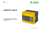
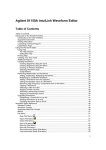
Isograph Reliability Software www.isograph-software.com NAP V1.0 Technical Specification NB: A helpful NAP Tutorial can be found as an appendix to this document Platform Runs under Windows 95, 98, NT, 2000, Me and Xp. Recommended host memory requirements: 128Mb+ Summary of capabilities : The Network Availability Program (NAP) enables users to predict/measure the availability of all types of communication networks, be they Carrier (mobile, fixed, data/packet) or Corporate (voice, data, services). The NAP network availability model utilizes an extended Reliability Block Diagram (RBD) methodology that addresses the specific characteristics of network elements and their connections. The effectiveness of network restoration after single or multiple failures may therefore be modelled accurately in NAP. In addition to predicting network availability, NAP also provides criticality rankings that identify weak spots in the network. Complex or simple networks may be defined and modelled by the User. Network elements may be logically modelled right down to part level, using the powerful NAP pagination facility. Individual network element diagrams have been extended beyond traditional RBDs to allow users to model multiple interfaces and their interactions with common equipment. In addition, NAP can include the effect of switching delays on network availability, using Markov Analysis. NAP Screen Shot Copyright Isograph 2005 Page 1 Isograph Reliability Software www.isograph-software.com Users may also restrict the analysis to network paths traversing a limited number of network elements (limiting the ‘hop’ number). This useful feature eliminates unrealistic ‘snake-like’ paths in complex networks. Failure data is normally specified in the library at the part level. Failure rates or MTTFs (Mean Time to Failure) may be specified for cards, shelves, etc. and ‘cuts per km per yr’ specified for cables (other units are available). Repair times may be specified at the network element or part level. NAP analyzes the network diagram using sophisticated minimal cut set generation algorithms allowing the effects of common failures to be modelled correctly. A wide range of network parameters (availability, reliability, MTBF, etc.) are calculated and presented to the user. Criticality rankings allow the user to identify weak spots and indicate the most effective way to improve network availability. One of the important features of NAP is that the modelling assumes data flow in both directions in a network path (non-directional), unless the user specifies data flow in one direction only (directional). This means that users need not be specific about the direction of data flow in the network, unless required. NAP will automatically determine the allowable paths between a source and target, and hence determine the minimal cut sets that determine the availability of the network. NAP provides many time-saving features to allow users to quickly construct the network diagram. These include a parts library facility that allows users to import their parts data in convenient groupings, a network element library facility that allows users to construct common network element diagrams and a fully interactive network diagram construction facility. NAP allows the user to quickly construct network diagrams using drag and drop facilities. Users may simply drag a network element or part from the library tree onto the network diagram. Once a network element is realised in the network diagram, you may modify the default parts (control, power, interface cards, etc.) associated with the element by selecting options from alternative part lists. The network element may then be interactively connected to other elements, through a chosen interface, simply by clicking the mouse. The NAP Report Generator permits a selection from a range of standard reports, or permits the user to quickly design his/her own customised reports. Design of headers and footers, choice of fonts, insert pictures, sorting and filtering of data and much more is permitted. Paginated network diagram reports are automatically produced and can be transferred to other packages such as Microsoft Word in the form of Windows metafiles. You may also choose from a wide range of sophisticated scientific graphs and charts, or create your own graphs and charts. You can display multiple graphs on the same page and easily modify scales, legends, titles etc. NAP provides a flexible import/export facility that allows the user to transfer data to and from Microsoft Access databases, Microsoft Excel spreadsheets and text delimited and fixed length files. www.isograph-software.com Page 2 Isograph Reliability Software www.isograph-software.com The Network Diagram Network Diagram Constructed in NAP NAP recognises the failure logic of the network from the network diagram entered by the user. The diagram represents how individual network element failures interact with other network element failures to prevent data flow between source and target nodes in the network. A network diagram entered into NAP (you may create more than one network diagram in the same project) specifies the possible communication paths between different network elements. The paths between network elements, which are defined with connections, may be directional or non-directional. A directional connection indicates that data may flow in one direction only. The network diagram will contain block symbols normally representing the network elements and the cables connecting the elements together. Typical network hierarchy www.isograph-software.com Page 3 Isograph Reliability Software www.isograph-software.com Network elements with multiple interfaces must be connected to other network elements via a specific interface (chosen by the user when making the connection). Each network diagram must have a single source node and single target node defined at the highest level. The source and target nodes indicate to NAP that the availability calculation should represent the probability that data flow is maintained between the two nodes. Users may also define sub-networks within the network diagram (e.g. for modelling self-healing ring technology). These sub-networks may also have source and target nodes defined. The availability of an individual network element is determined by the availability of the shelves and cards that constitute the network element. The cards, shelves and network elements are defined in the Parts Library, along with the associated Availability/Reliability data. Some network elements may contain redundancy arrangements designed to increase availability. In addition, network elements with multiple interfaces will often use common equipment. In order for NAP to correctly determine the availability of these arrangements, it is necessary to draw an element diagram to represent the failure logic. In fact, the element diagram is really no different from the network diagram. It is an extended reliability block diagram (RBD) that can handle multiple interfaces and multi-directional data flow. Typical Element Hierarchy www.isograph-software.com Page 4 Isograph Reliability Software www.isograph-software.com Network and element diagrams consist of blocks and nodes connected together in parallel and series arrangements. The blocks in a network diagram usually represent network elements and cables. The nodes in a network diagram are used to position connecting lines and specify the data flow source and target for the availability calculation. The nodes in an element diagram are used to position connecting lines and specify vote arrangements. Element diagrams are usually constructed as part of the network element library in NAP. However, they may be constructed or modified by ‘paging down’ from a selected network element in the network view. During availability calculations, NAP will be able to determine whether the system has failed or not by examining the network diagram entered by the user. The program does this by determining whether there are any open paths from the source node to the target node. For paths traversing network elements with multiple interfaces, NAP takes into account the interface connections made by the user. Program Operation NAP employs standard Windows menus and dialogs to control the operation of the program. This ensures that new NAP users may rapidly familiarize themselves with program operation with minimal reference to the user manual. A standard Windows on-line help facility is also provided, including context-sensitive help for dialogs (accessed by pressing the Help button when the dialog is displayed). Pull-down menus and their options may be selected using the left mouse button. Accelerator keys are provided for selected menu options. For example, tapping the Delete key will delete selected symbols in the block diagram. On starting the program, the NAP window will be displayed covering the full screen. This window may be resized or iconified at any time, by selecting window reconfiguration options from the top right corner of the window border. The principal pull-down menu options are positioned along the top of the main NAP window. www.isograph-software.com Page 5 Isograph Reliability Software www.isograph-software.com Immediately below these menu options reside a group of controls which form a toolbar, allowing the user to access some of the more extensively used menu options directly. Diagram mode tabs are positioned just below the toolbar. These tabs allow the user to display ‘Networks’, ‘Block Library’, ‘Tables’ or ‘Results’ data in the windows below the tabs. When the ‘Networks’ tab is selected, the program will display project network diagrams in the right-hand window. The user may navigate between different networks and different lower level page views of the same network by making selections from the combo-box above the right-hand window. When the ‘Block Library’ tab is selected, the program will display library block diagrams in the right-hand window. The user may navigate between different blocks in the library by making selections from the combo-box above the right-hand window. Selecting the ‘Page Down’ or ‘Page Up’ toolbar options will allow the user to navigate between different diagram pages for the same library block. Library blocks may be created to represent generic network element block diagram structures that may be copied into a network diagram. Library blocks may also be created to represent common cause failures that may affect more than one network element at the same time. When the ‘Tables’ tab is selected, the program will display parts, components, elements or bitmap data in a table format. A tab at the bottom of the right-hand window allows users to navigate between these table types. Find, replace and filter functions are available from the pull-down menus and toolbars. When the ‘Results’ tab is selected, NAP displays criticality graphs. Criticality data is only displayed when the results are up-to-date following a valid analysis. At the bottom of the screen is positioned a message strip. Note that this message strip may be used to provide help on the functionality of pull-down menu options. As a pull-down menu option is highlighted (but before it is selected), the message strip indicates its functionality. Summary help is provided on toolbar options by moving the mouse cursor over the appropriate option. The summary help information will appear immediately below the option. At the bottom right of the NAP screen, a small secondary message strip shows the number of parts and blocks in the current project (including blocks associated with library network elements). The left-hand NAP window always displays a tree control. The tree control enables the user to navigate the parts library, block library, networks and bitmap tables. The parts library consists of part category groups and part list groups. Each part must be attached below a part category group. Each part list definition must be attached below a part list group. Users may create part category groups to represent any type of categorisation and sub-categorisation of parts. This allows speedy navigation of the www.isograph-software.com Page 6 Isograph Reliability Software www.isograph-software.com parts library to locate a certain part type. Part list groups may be created below other part list groups or below a part category group. The block library may consist of network element groups and common cause failure groups. Each network element in the block library must be attached below a network element group. Common Cause Failure blocks must be attached below a Common Cause Failure group. Users may create network element groups to represent any type of categorisation and sub-categorisation of library network elements. Users may also create CCF groups to represent any type of categorisation and sub-categorisation of CCF blocks. The network section of the tree allows users to navigate between different networks. The bitmap library allows users to create a table of bitmaps that may be used in network diagrams. To make a selection in the tree control, the user must click the left button of the mouse over any object in the tree. The newly selected object will now be highlighted. NAP provides a facility to allow the user to open and close objects in the tree control. Closed objects do not display their children. This is an important facility when manipulating large projects as it allows the overall block diagram display to be reduced significantly in size. Objects may be opened or closed by clicking the left mouse button over the ‘+’ or ‘-’ box to the left of the appropriate object. Note that double-clicking the left mouse button over some objects will result in that object's parameters being displayed in a parameter edit dialog. This is provided as a speed-up facility for editing parameters. NAP allows the selection of multiple objects in the tree control at the same time, so long as the selected objects appear under the same parent. In order to select multiple objects in the tree control, the user must hold down the control key whilst selecting additional objects by clicking the left mouse button. If the user needs to select a large number of adjacent objects at the same time then this may be achieved using the shift key. If an object is selected with the shift key held down then all objects between the selected object and the previously selected component will be highlighted. Single objects may be deselected by holding the control key down and clicking the left mouse button. NAP provides pop-up menus containing some of the most frequently used options. To reveal a pop-up menu, simply click the right mouse button with the cursor positioned in the left or right windows. www.isograph-software.com Page 7 Isograph Reliability Software www.isograph-software.com Appendix – NAP Tutorial This tutorial provides users with a basic step-by-step guide on how to construct and analyze a simple network using NAP. Before starting the tutorial, open the demonstration NAP project demo.nap. Constructing a Part Library The NAP Part Library contains parts and part lists that may be attached to component blocks (blocks representing cards, cables and other components that may influence the availability of the network) in the network diagram. A single part type (defined uniquely by its vendor and part number) will normally be associated with a failure rate or mean time to failure (MTTF) that defines the failure characteristics of the part (the failure rate and MTTF are equivalent parameters and the user may decide which format is more suitable – failure rate = 1/MTTF). Any network component that is to be included in the network availability model must be defined as a part in the part library. Cables must therefore be defined as parts. They will be associated with a special failure parameter that specifies the failure rate per unit length of cable. In certain rare circumstances, you might need to directly associate a part with an unavailability value, rather than a failure rate or MTTF. Part and part list definitions organised into groups. The green book symbols represent part category groups, the green rectangular symbols represent part definitions, the yellow book symbols represent part list groups and the yellow block definitions represent part list items. A part library may contain many thousands of parts (even if they are not all being currently used in your network model) and therefore some method of grouping these www.isograph-software.com Page 8 Isograph Reliability Software www.isograph-software.com parts is required, to allow the user to easily locate the correct part when it needs to be associated with a block in the network diagram. NAP provides a part grouping facility that allows a user to construct groups and sub-groups through an unlimited number of hierarchical levels. Each part must be defined under a single group. You cannot define a part (with the same vendor and part number) twice in the same part library. As you add new parts to the part library, you will be able to retrieve the part data simply by double-clicking on the part in the tree control in the left-hand NAP window. Try double-clicking the left mouse button over some of the existing part definitions (green rectangular symbols) in the demonstration project library. A dialog will appear showing the parameters specified for each part. We will now create a new part group below an existing part group and then add a new part to the library. - Select the ‘Interface cards’ part group with a single click of the left mouse button. Press the right mouse button over the ‘Interface cards’ part group in the tree control. The group will become selected and a pop-up menu will appear. -Select the ‘Add Group’ option. Part Group Dialog The ‘Part Group’ dialog will appear, allowing you to enter a new group description (say ‘High speed interface cards’). The ‘Category Group’ button should be selected. - Select OK to create the new part group. We will now add a new part. - Select the new part group with the right-hand mouse button and select the ‘Add Part’ option from the pop-up menu. The Part dialog will appear, allowing you to enter data for the part. www.isograph-software.com Page 9 Isograph Reliability Software www.isograph-software.com Part Dialog You must provide a part number. You do not have to enter anything into the vendor field. However, the part number and part vendor uniquely define a part, so if you are likely to have two parts with the same part number but originating from different vendors, you should complete the vendor field. - Select OK to create the new part. In addition to defining individual parts, the part library allows users to define ‘Part Lists’. The ‘Part Lists’ are an optional function of the part library. However, they can be very useful if you are later going to vary the part being used for a given function. For example, a slot/backplane on a given shelf within a network element could contain an interface card at a specific capacity; the slot/backplane may support various interface cards at different levels of capacity. It would be useful to be able to select a permissible interface card with the appropriate capacity from an alternative part list. Users may set up part lists of alternative parts in the part library and then associate the list with an individual component block in a network element. To define a ‘Part List’ you must first create a ‘Part List Group’. Creating a ‘Part Group’, then changing the type of group from ‘Part Group’ to ‘List Group’ in the Part Group dialog, will do this. (see above) ‘Part List Groups’ may be created underneath part category groups or underneath other part list groups. The part list may then be defined by dragging a part definition (green rectangular block) onto a part list group (yellow book) in the tree control. Another way of adding to a part list is to - Select the part list group with the right mouse button and then - Select ‘Add Part to List’ from the pop-up menu. www.isograph-software.com Page 10 Isograph Reliability Software www.isograph-software.com Two part lists defined in the part library (yellow symbols). The green symbols represent the part definitions. Identical parts (with the same vendor and part number) may be repeated in part lists but their original definitions (green symbols) can occur only once in the part library. Try adding one or two new part list groups and defining a list of parts below them, using the demonstration project. You can copy existing lists and modify them if you wish, using the Copy, Paste and Delete options on the right button pop-up menu. Adding Network Elements to the Block Library Once you have entered some parts into the part library, you can start building a network diagram. However, many users will find it beneficial to build a library of common network element types before constructing the network diagram. This will allow common network element structures to be copied from the library into the network diagram, reducing the time spent constructing a network model. The block library is also used to hold single blocks or block structures that represent high-level essential services shared between multiple network elements. These blocks are known as ‘Common Cause Failure Blocks’, as failure of these blocks will result in the simultaneous unavailability of all the associated network elements. First, we will deal with the use of the block library to construct a commonly occurring network element that may be used over and over again in network models. We will recommend a structure for the network element block diagram. However, this structure is only a recommendation for communication networks and the user may wish to organise network element block diagrams using a different scheme. Block diagrams are constructed in the right-hand NAP window. We will first look at a library network element that has already been constructed in the demonstration project (and illustrated below). In the demonstration project, select the ‘Block Library’ tab above the right-hand window. www.isograph-software.com Page 11 Isograph Reliability Software www.isograph-software.com - Select the E1 network element in the tree control (this appears underneath the ‘Block Library’ and ‘COMPLEX’ nodes). You will then see the top-level diagram representing library network element E1. It is often convenient to arrange network elements with respect to the shelves holding electronic cards. In this example, we have constructed two shelf blocks. - Double click the left mouse button with the cursor positioned over one of the shelf blocks. A dialog will appear showing the attributes of the block. The block type has been set to ‘Shelf’. This allows NAP to organize the blocks representing the slots on shelves at lower levels in the block diagram. Select ‘Shelf 1’ and then select the ‘View, Page Down’ pull-down menu option or equivalent toolbar button. The block diagram for shelf 1 will now be displayed. Note that the connections in both diagrams so far are non-directional (there are no arrows). This effectively indicates that data can flow in either direction through the connections. - Double-click the left mouse button with the cursor positioned over the ‘Network interface 2’ block. - Select the ‘Sockets’ tab in the dialog that appears. You will see that this block has been defined as a socket block. This tells NAP that a user can connect to this block from the external network. - Cancel the dialog and double-click on the ‘Inter-shelf interface’ block. - Select the ‘Sockets’ tab in the dialog that appears. You will see that this block has also been defined as a socket block but the socket has been restricted to next level connections. This indicates to NAP that the connection for this block may only be made between the shelf blocks at the level above. - Select the ‘Network interface 2’ block and then select the ‘View, Page Down’ pulldown menu option or equivalent toolbar button. NAP will now display the component blocks at the lowest hierarchical level. www.isograph-software.com Page 12 Isograph Reliability Software www.isograph-software.com - Double-click on any of the component blocks. The ‘Library Component’ dialog will appear. Select the various tabs to view the data associated with the component. Library Component Dialog Library Network Elements are held in the Block Library underneath Block Groups. Block Groups may be created in a similar fashion to Part Groups. Simply - Select the Block Library node in the tree control, or an existing Block Group, with the right mouse button and - Select the ‘Add Group’ option from the pop-up menu. The Block Group dialog will appear, allowing you to enter a description for the network element group. You may then create new network elements in the library by selecting a network element group with the right mouse button and then selecting the ‘Add Network Element’ option in the pop-up menu. A blank canvas will appear in the block diagram drawing area in the NAP right-hand window. You may then construct a network element block diagram by selecting the ‘Add’ pull-down menu options (or equivalent toolbar button) and placing blocks, nodes and connections in the diagram by clicking the left mouse button. When you want to ‘drill down’ to a lower level, select an existing block and then use the ‘View, Page Down’ pulldown menu option or equivalent toolbar button. You may then continue to add new blocks at the lower level. When you reach the lower level you may also create component blocks by dragging the appropriate part or part list from the tree control into the diagram. Constructing a Network Diagram A network block diagram is constructed by first creating a top-level network in the tree control and then adding blocks, nodes and connections to the network diagram in the right-hand window. When you start a new project, NAP automatically creates a single network (called N1) and places a source and target node within the drawing area, representing the network block diagram. If you wish to create additional networks, this may be done by: www.isograph-software.com Page 13 Isograph Reliability Software www.isograph-software.com - Selecting Networks in the tree control using the right button and then - Selecting ‘Add Network’ from the pop-up menu. You may add blocks, elements, nodes and connections using the options on the ‘Add’ pull-down menu. Alternatively, you may drag and drop parts and part lists from the part library. If you have constructed network elements in the network element library then you may also drag these into the network block diagram. NAP will produce a copy of the network element block structure that may be modified, if necessary, independently from the library structure. If you attempt to add a connection to or from a network element that has socket blocks defined below it (blocks with sockets defined below them are referred to as complex blocks by NAP) then NAP will reveal a ‘Socket Selection’ dialog, allowing you to specify the interface block you wish to connect to. Each network diagram must have a single source and target node defined at the top level. During an analysis NAP will trace all possible paths from the source node to the target node (up to a user-specified network element hop count), taking into account any restrictions indicated by directed connections. - Select the Networks tab above the right-hand window for the demonstration project. - Select network N1 in the tree control to display the top-level network diagram. You will see that a network diagram has already been constructed, using network elements from the network element library and cable parts directly from the part library. As you move the cursor over the connection to the network element, the description of the lower level socket block will appear. Try dragging and dropping one or two more network elements from the network element library into the diagram. Drag in some cables from the part library and then connect them to the existing diagram. You do not need to construct a network diagram using the network element library at all, if you wish. If you prefer, you could simply add and connect new blocks directly to the network diagram. Component blocks could then be directly associated with a part in the part library. Performing an Analysis To perform an analysis select the ‘Analysis, Start’ pull-down menu option or equivalent toolbar button. If there are any logical errors in the network diagram you have constructed, NAP will inform you of these errors and abort the analysis. If there are no errors, NAP will proceed to determine the paths through the network. Then NAP will determine the minimal ‘Cut Sets’ or ‘Failure Sets’ for each network and for simple blocks defined within each network. The minimal cut sets represent minimal combinations of failures that would result in loss of network availability (the network is assumed to be available if at least one path is maintained between the source and target nodes). The probability of the cut sets/failure sets is determined and the program determines the ‘network unavailability’ and other network performance www.isograph-software.com Page 14 Isograph Reliability Software www.isograph-software.com parameters. The ‘network unavailability’ is the probability that the network will be unavailable at any time. Results Dialog Displaying Summary Parameters for the Network After performing an analysis, NAP will display a results dialog displaying the various predicted performance parameters. The results dialog will also display criticality rankings. Criticality rankings indicate the sensitivity of network availability and failure frequency to the reliability of individual blocks in the network diagram. This allows users to determine the weak links in the network. Further detail is available in the NAP V1.0 User Manual. www.isograph-software.com Page 15