1
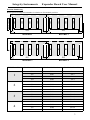
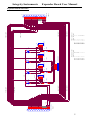
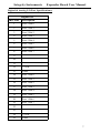
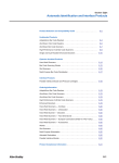
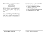
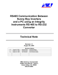
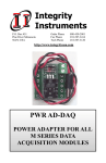
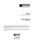
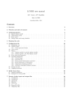
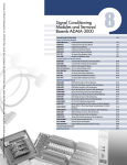
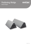
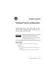
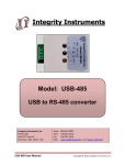
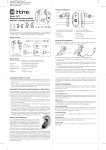
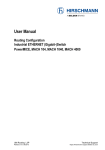
Integrity Instruments
Expander Board User Manual
Integrity
Instruments
P.O. Box 451
Pine River Minnesota
56474 USA
Order Phone
Fax Phone
Tech Phone
800-450-2001
218-587-3414
218-587-3120
http://www.integrityusa.com
EXP-STA
EXP-TRK
Digital I/O
Mounting Boards
1
Integrity Instruments
[Dimensions 3” x 4 7/8” excluding connectors]
Board 1 P2B1
Board 2 P2B5
Board 3 P1B1
Board 4 P1B5
D2
JS1
JS4
F4
JS4 PIN 1
JS3 PIN 2
JS3 PIN 1
F3
P2
8
JS2 (I/O Module)
JS3 (I/O Module)
JS4 (I/O Module)
JS3
PIN 2
JS4
PIN 1
JS4
PIN 2
PIN 1
PIN 2
PIN 3
PIN 4
PIN 5
PIN 6
PIN 7
PIN 8
JSx PIN 1
AC INPUT
AC OUTPUT
DC INPUT
JSx PIN 1
JS3
PIN 1
JSx PIN 2
JS2
PIN 2
JSx PIN 1
JS2
PIN 1
JSx PIN 2
JS1
PIN 2
JSX PIN 2
JS1
PIN 1
JSx PIN 1
JS5 Terminal Strip
JS2 PIN 2
JS2 PIN 1
JS1 (I/O Module
D4
JS3
F2
JS1 PIN 2
JS5
JS1 PIN 1
1
D3
JS2
F1
P1
Board 1 P2B3
Board 2 P2B7
Board 3 P1B3
Board 4 P1B7
JSx PIN 2
D1
Board 1 P2B2
Board 2 P2B6
Board 3 P1B2
Board 4 P1B6
JS4 PIN 2
EXP-X PCB Details
Board 1 P2B0
Board 2 P2B4
Board 3 P1B0
Board 4 P1B4
Expander Board User Manual
DC OUTPUT
I/O Modules
The module inputs and outputs are connected to JS5. In the case of DC units polarity must be observed,
and is shown above. There are many other modules which can be used, the only criteria being that the
internal logic levels must be 5 vdc.
Fuses are 5 x 20 mm, 3.15 amp
The table below shows some of the manufacturers, and some of the applicable modules.
Module Color
WHITE
RED
YELLOW
BLACK
2
Module type
Crouzet (Gordos)
Grayhill
Opto22
Potter & Brumfield
WRCAkron
DC Input
IDC5
70-IDC5B
IDC5
IDC-5
1781-IB5S
DC Output
ODC5
70-ODC5
ODC5
ODC-5
1781-OB5S
AC Input
IAC5
70-IAC5
IAC5
IAC-5
1781-IA5S
AC Output
OAC5
70-OAC5
OAC5
OAC
1781-OA5S
Integrity Instruments
Expander Board User Manual
Position Numbering
Board position and port/bit number in relation to I/O module position.
P2B1
P2B2
P2B3
P2B4
P2B5
P2B6
P2B7
BOARD 1
BOARD 2
P1B3
P1B4
2
3
4
P1B6
JS4
P1B7
P2
JS5
JS5
BOARD 3
BOARD 4
JS4
P1
JS1
JS4
JS3
JS2
JS1
P1
P1B5
JS3
P1B2
P2
1
JS3
JS5
P1B1
EXP-X BOARD #
JS2
JS4
JS3
JS2
JS5
JS2
P1B0
P2
JS1
P2 P1
JS1
DATA MODULE
P2B0
P1
I/O Module Number
I/O Port/Bit Number
I/O Module Port Pin#
JS1
P2B0
Pin 1
JS2
P2B1
Pin 2
JS3
P2B2
Pin 3
JS4
P2B3
Pin 4
JS1
P2B4
Pin 5
JS2
P2B5
Pin 6
JS3
P2B6
Pin 7
JS4
P2B7
Pin 8
JS1
P1B0
Pin 14
JS2
P1B1
Pin 15
JS3
P1B2
Pin 16
JS4
P1B3
Pin 17
JS1
P1B4
Pin 18
JS2
P1B5
Pin 19
JS3
P1B6
Pin 20
JS4
P1B7
Pin 21
3
Integrity Instruments
Expander Board User Manual
Operational Characteristics
The Integrity Instruments EXP-X boards mate up directly to our line of I/O data acquisition modules.
The boards are designed to allow expansion for up to 16 digital I/O points. If you need more than the 4 I/O
points just plug in another board. This can be done for up to 4 EXP-X boards. All 16 I/O points, plus voltage and ground are available at the male DB 25 connector on the first board. This is accomplished by data
line rollover shown in the diagram below.
MALE DB LEFT
DB PIN # SIGNAL
PIN 1
P2 B0
PIN 2
P2 B1
PIN 3
P2 B2
PIN 4
P2 B3
PIN 5
P2 B4
PIN 6
P2 B5
PIN 7
P2 B6
PIN 8
P2 B7
PIN 14
P1 B0
PIN 15
P1 B1
PIN 16
P1 B2
PIN 17
P1 B3
PIN 18
P1 B4
PIN 19
P1 B5
PIN 20
P1 B6
PIN 21
P1 B7
PIN 24
+5V
PIN 22
+5V
PIN 25
GND
PIN 13
GND
FEMALE DB RIGHT
DB PIN # SIGNAL
PIN 1
P2 B4
PIN 2
P2 B5
PIN 3
P2 B6
PIN 4
P2 B7
PIN 5
P1 B0
PIN 6
P1 B1
PIN 7
P1 B2
PIN 8
P1 B3
PIN 14
P1 B4
PIN 15
P1 B5
PIN 16
P1 B6
PIN 17
P1 B7
PIN 18
P2 B0
PIN 19
P2 B1
PIN 20
P2 B2
PIN 21
P2 B3
PIN 24
+5V
PIN 12
+5V
PIN 25
GND
PIN 13
GND
Nomenclature
The boards are marked to show the specific port and bit number for each I/O point used with our data
acquisition modules.
There are two ports, P1 and P2, and eight bits per port B0 to B7. The designation P2B3 is Port 2 Bit 3.
When all 4 boards are series connected, the input end is board 1, then board 2, 3, and 4. The marking on
the board shows what port and bit number controls that I/O position on the board, depending on what board
number it is in the connection series. See figures on page 3.
The left column in the diagram above shows the DB 25 pin number and its’ relation to the specific I/O
points on each board.
By using the Integrity Instruments DB25FTS adapter the expander board may be used with any I/O
controller You need only to supply the unit with power and the proper signal lines for functionality.
MODELS:
4
EXP-TRK -------------Track mount in Snaptrack®
EXP-STA -------------Standoffs 1/2 inch, hollow for 6/32 mounting screws
1
14
2
15
3
16
4
17
5
18
6
19
7
20
8
21
9
22
10
23
11
24
12
25
13
MALE
CONNECTOR DB25
P1
GND
VCC
PORT 1 BIT 0
PORT 1 BIT 7
PORT 2 BIT 0
PORT 2 BIT 7
D1
LED
FUSE
F1
3.3K
R1
5
4
3
2
1
JS1
D2
LED
CONN SOCKET 5
5
4
3
2
1
GND
VCC
FUSE
F2
3.3K
R2
5
4
3
2
1
JS2
CONN SOCKET 5
5
4
3
2
1
D3
LED
1
2
3
4
5
6
7
8
1
2
3
4
5
6
7
8
BIT 0
BIT 1
BIT 2
BIT 3
BIT 4
BIT 5
BIT 6
BIT 7
5
4
3
2
1
5
4
3
2
1
JS3
D4
LED
CONN SOCKET 5
PORT 2 BIT 0 TO 7
INPUT OUTPUT
1
18
2
19
3
20
4
21
5
1
6
2
7
3
8
4
CONN SOCKET 8
JS5
FUSE
F3
3.3K
R3
FUSE
F4
3.3K
R4
5
4
3
2
1
JS4
BIT 0
BIT 1
BIT 2
BIT 3
BIT 4
BIT 5
BIT 6
BIT 7
CONN SOCKET 5
5
4
3
2
1
PORT 1 BIT 0 TO 7
INPUT OUTPUT
14
5
15
6
16
7
17
8
18
14
19
15
20
16
21
17
PORT 1 BIT 0
PORT 1 BIT 7
PORT 2 BIT 0
PORT 2 BIT 7
GND
VCC
P2
FEMALE
CONNECTOR DB25
1
14
2
15
3
16
4
17
5
18
6
19
7
20
8
21
9
22
10
23
11
24
12
25
13
Integrity Instruments
Expander Board User Manual
Expander Board Schematic
5
Integrity Instruments
Expander Board User Manual
I/O Modules Specifications available from Integrity Instruments
PART NUMBER
FUNCTION
RANGE
TURN ON TIME TURN OFF TIME
1781-IB5S
DC INPUT
3.3 to 32 VDC
.3 milli-seconds
.6 milli-seconds
1781-OB5S
DC OUTPUT
3 to 60 VDC 3A
.05 milli-seconds
.1 milli-seconds
1781-IA5S
AC INPUT
90 to 140 VAC
20 milli-seconds
30 milli-seconds
1781-OA5S
AC OUTPUT
12 to 140 VAC 3A
N/A
N/A
I/O Modules Internal Schematic and Exp Board Connections
1781OB5S
3-60 VDC OUTPUT
VCC
1781IB5S
3.3-32 VDC INPUT
VCC
DC output
DC intput
3.3K
3.3K
LED
3
LED
1
2
1
2
3
4
5
2
1
JS5
1
2
1
2
1
2
3
4
5
3
JS5
2
TO DIG I/O
1
TO DIG I/O
PINNING
PIN 1
PIN 2
PIN 3
PIN 4
PIN 5
+ INPUT
- INPUT
VCC
TO MPU
GND
+ OUTPUT
- OUTPUT
VCC
TO MPU
GND
- AS OUT + AS IN
1781OA5S
12-140 VAC OUTPUT
VCC
1781IA5S
90-140 VAC INPUT
VCC
AC output
AC intput
3.3K
3.3K
1
2
3
4
5
1
2
4 -
1
2
3
4
5
3
1
2
JS5
6
2
TO DIG I/O
1
TO DIG I/O
+ 2
3
2
1
1
LED
LED
JS5
Integrity Instruments
Expander Board User Manual
Digital & Analog I/O Port Specifications:
Digital I/O
DB25 Pins
Description
1
Port 2 Bit 0
2
Port 2 Bit 1
3
Port 2 Bit 2
4
Port 2 Bit 3
5
Port 2 Bit 4
6
Port 2 Bit 5
7
Port 2 Bit 6
8
Port 2 Bit 7
9
10
11
12
+5Vdc
13
GND
14
Port 1 Bit 0
15
Port 1 Bit 1
16
Port 1 Bit 2
17
Port 1 Bit 3
18
Port 1 Bit 4
19
Port 1 Bit 5
20
Port 1 Bit 6
21
Port 1 Bit 7
22
23
24
+5Vdc
25
GND
7
Integrity Instruments
Expander Board User Manual
NOTES
WARRANTY
Integrity Instruments warranties all products against defective workmanship and
components for the life of the unit. Integrity Instruments agrees to repair or replace, at
it’s sole discretion, a defective product if returned to Integrity Instruments with proof of
purchase. Products that have been mis-used, improperly applied, or subject to adverse
operating conditions fall beyond the realm of defective workmanship and are not
convered by this warranty.
Copyright © 2000-2003, Integrity Instruments, Inc.
All trademarks and/or registered trademarks are the property of their respective
owners.
Revision: August 28, 2003 - v3.0
8