1
User’s Manual
for the:
Novell NetWare
Operating Systems
with
Microsoft Windows
Microsoft Windows for Workgroups
Clients
2
Licensing Agreement
YOU SHOULD CAREFULLY READ THE FOLLOWING TERMS AND
CONDITIONS BEFORE OPENING THE SOFTWARE PACKAGE.
YOUR USE OF THE MEDIA ON WHICH THE PROGRAM IS
RECORDED INDICATES YOUR ACCEPTANCE OF THESE TERMS
AND CONDITIONS. IF YOU DO NOT AGREE WITH THEM, YOU
SHOULD IMMEDIATELY RETURN THIS PACKAGE AND YOUR
MONEY WILL BE REFUNDED.
LICENSE
You may:
1.
Use the program on a single computer.
2.
Merge other programs with the program as specified in the
enclosed materials for your use on a computer. The program
merged with another will continue to be subject to the terms and
conditions of this agreement.
3.
Transfer the program and license to another party if the other
party agrees to accept the terms and conditions of this
agreement.
YOU MAY NOT USE OR TRANSFER THE PROGRAM IN WHOLE OR
IN PART EXCEPT AS EXPRESSLY PROVIDED IN THIS LICENSE.
YOU MAY NOT MERGE THE PROGRAM WITH ANY OTHER EXCEPT
AS EXPRESSLY PROVIDED FOR IN THE LICENSE.
YOU MAY NOT COPY OR MODIFY THE PROGRAM IN WHOLE OR IN
PART.
TERMS
The license is effective until terminated. You may terminate it at any time
by destroying the diskettes or tape (hereby known as “media”) contained
in this package. Terminating the license does not eliminate any prior
failure on your part to comply with any term or condition of this
agreement. You agree further upon termination to destroy the program
together with any unpermitted copies, modifications and/or merged
portions in any form.
3
LIMITED WARRANTY
THE PROGRAM AND ENCLOSED MATERIALS ARE PROVIDED “AS
IS’ WITHOUT WARRANTY OF ANY KIND, EITHER EXPRESSED OR
IMPLIED, INCLUDING BUT NOT LIMITED TO THE IMPLIED
WARRANTIES OF MERCHANTABILITY AND FITNESS FOR A
PARTICULAR PURPOSE. THE ENTIRE RISK AS TO QUALITY AND
PERFORMANCE OF THE PROGRAM AND ENCLOSED MATERIAL IS
ASSUMED BY YOU.
However, to the original purchaser only, Para Systems, Inc. does warrant
the media on which the program was recorded to be free from defects in
materials and faulty workmanship under normal use and service for a
period of thirty (30) days from the date of purchase. If during the thirty
(30) day period, a defect occurs, then the media will be replaced without
charge to you provided that (1) you have previously sent in your Warranty
Registration card or you send proof of purchase and (2) return the
defective diskette to Para Systems, Inc. Contact Technical Support for
an RMA number and instructions.
LIMITATION OF REMEDIES
Para Systems, Inc.’s entire liability and your exclusion remedy shall be
replacement of the media if you have met the conditions as described
under “Limited Warranty”.
In no event will Para Systems, Inc. be liable to you for any other damages
arising out of your use of this program.
OTHER
THIS AGREEMENT WILL BE GOVERNED BY THE LAWS OF THE
STATE OF TEXAS.
YOU ACKNOWLEDGE THAT YOU HAVE READ THIS AGREEMENT,
UNDERSTAND IT AND AGREE TO BE BOUND BY ITS TERMS AND
CONDITIONS. YOU FURTHER AGREE THAT THIS IS THE SOLE
AGREEMENT BETWEEN US AND SUPERSEDES ANY PROPOSAL
OR AGREEMENT ORAL OR WRITTEN BETWEEN US RELATING TO
THE SUBJECT MATTER.
(Some states do not allow the exclusion or limitation of liability for
consequential or incidental damages, so the above limitations may not
apply to you.)
4
Trademarks
Sentry is a registered trademark of Para Systems, Inc.
Novell and NetWare are registered trademarks of Novell, Inc.
Microsoft, MS, and Windows are registered trademarks of Microsoft
Corporation.
All other brand and product names are trademarks or registered
trademarks of their respective holders.
Copyright© 1997 by:
Para Systems, Inc.
Printed in U.S.A.
Unauthorized reproduction prohibited.
5
Conventions Used In This Guide
This guide uses these type style conventions:
Italic print, as shown in this example, indicates chapter or section names
in this guide, window or dialog box names, or is used for emphasis.
Bold italic print, as shown in this example, indicates field names or
menu items in the software, or is used for emphasis. Words separated
by a | vertical bar indicate a series of menu items that must be selected.
For example: File|Exit
Bold print, as shown in this example, indicates filenames, directories, or
items to be typed exactly as they appear.
Italic print words or letters in braces { } indicate values that must be
supplied by the user. For example: {drive}:\install
Italic print words or letters in brackets < > indicate keys to press. If two
keys are separated by a + plus symbol, then the first key should be
pressed and held down while pressing the second key. For example:
<alt+enter>
NOTE: Notes contain important information
set off from the text.
WARNING: Warning messages alert you to a specific
procedure or practice which, if not followed correctly,
could cause serious personal injury or loss of data.
6
1. INTRODUCTION..................................................................... 8
2. INSTALLATION & CONFIGURATION ................................. 10
System Requirements ................................................................ 10
Installing the UPS Interface Cable ............................................. 10
Serial Port Addresses................................................................. 11
Installing Sentry .......................................................................... 12
Configuring Sentry...................................................................... 12
Beyond UPS Configuration .................................................. 12
3. STARTING & STOPPING SENTRY ..................................... 14
Loading SMARTMON.NLM ........................................................ 14
Loading AIO Drivers............................................................. 14
Loading Support NLMs ........................................................ 14
Loading Sentry..................................................................... 14
Loading Automatically.......................................................... 15
Unloading SMARTMON.NLM..................................................... 15
Starting the Sentry Client............................................................ 16
Deleting Sentry ........................................................................... 17
Sentry Server ....................................................................... 17
Sentry Client ........................................................................ 17
4. UPS CONFIGURATION........................................................ 18
5. MONITORING CENTER CONFIGURATION ....................... 20
Readings .................................................................................... 21
Meters ........................................................................................ 22
Changing Servers....................................................................... 23
Exiting Sentry ............................................................................ 23
6. EVENT CONFIGURATION ................................................... 24
User-Defined Event Configuration.............................................. 25
Event Action Configuration......................................................... 26
Shutdowns ........................................................................... 26
Logging ................................................................................ 27
Broadcasting ........................................................................ 28
Paging.................................................................................. 30
7
Common Modem Commands ............................................. 32
Email .......................................................................................... 33
Commands ................................................................................. 34
7. DATA & EVENT LOGGING .................................................. 35
Logging Configuration ................................................................ 35
Data History Graph..................................................................... 36
Data Log Viewer ......................................................................... 38
Event Log Viewer ....................................................................... 39
Event Calendar........................................................................... 40
8. SCHEDULING....................................................................... 41
9. UPS CONTROL OPTIONS................................................... 44
10. TROUBLESHOOTING........................................................ 45
Common Problems and Solutions.............................................. 45
11. PLACING A TECHNICAL SUPPORT CALL ...................... 47
8
Sentry is a UPS power monitoring application for Novell NetWare
operating systems. Sentry monitors the UPS through a cable attached to
a serial port on the computer, and the communication interface on the
UPS. This cable enables Sentry to check the status of the UPS and to
perform a graceful operating system shutdown if required.
Through Sentry’s pull-down menus and dialog boxes, you can configure
the user interface and shutdown timers, view and print event logs, view
and print power history graphs and data logs, and get help on-line.
You can configure Sentry to perform appropriate actions when an event
is detected. The user configurable actions include: logging,
broadcasting, paging, command file execution, and operating system
shutdown. You can set the delays and intervals of these actions. For
example, if utility power fails, you may wish to log the event, broadcast a
warning message, page the system administrator, and shutdown the
system after a delay.
The monitoring screen displays readings and meters for the UPS. You
can configure what values are displayed, and color coded ranges for the
values.
You can select readings to log for later viewing. The frequency of data
logging is user defined. The event log tracks the history of power and
UPS related events. The data log can be viewed, graphed, or printed.
The event log can be viewed or printed.
You can schedule actions, such as system shutdown, restart, and selftests. You can schedule actions recurring one-time, daily, weekly, biweekly, or monthly. Some actions may not be available because they are
not supported by your UPS model.
9
REMEMBER
Don’t forget to mail your Sentry registration card,
it is your proof-of-purchase.
NOTE
If you have any questions about Sentry or other
products from Minuteman, please contact us at:
Para Systems, Inc.
1455 LeMay Dr.
Carrollton, Tx 75007
Phone:(972) 446-7363
Fax: (972) 446-9011
QuickFax Info System: 1-800-263-3933
Internet: www.minuteman-ups.com
For Technical Support, see the section titled,
Placing a Technical Support Call.
10
System Requirements
1. To use Sentry, your server must be running one of the following
operating systems:
• NetWare v4.10
• NetWare v3.12
Your workstation must be running one of the following:
• Microsoft Windows
• Microsoft Windows for Workgroups
2. Your workstation must be using NetWare Client VLMs version 1.20
or higher.
3. Sentry requires one dedicated RS-232 serial port on your computer,
for communications with a UPS.
Installing the UPS Interface Cable
Before you attach the cable to the UPS or computer, please perform the
following steps:
1. Shutdown and turn off your computer.
2. Locate the UPS interface cable that was provided in the Sentry kit, or
with your UPS.
Install the UPS interface cable by performing the following steps:
1. Identify the computer end of the cable. All cables will have a label on
the computer end.
2. Plug the connector at the computer end of the cable into any
dedicated serial communications port on your computer. If this end
of the cable does not match your serial port connector, use an RS232 adapter.
3. Plug the connector at the other end of the cable into the interface port
on the UPS. (Refer to your UPS user’s manual for help in locating
the interface port.) If this end of the cable does not match the
connector on your UPS, contact your reseller or Para Systems
representative for a different cable. Do not use an adapter.
4. Restart your UPS and computer.
11
Serial Port Addresses
Sentry requires one serial s port for UPS monitoring, and an optional
second port used for alerting an administrator via a modem. You need
the AIO addresses for the ports during installation. Determine the
addresses before proceeding with the installation.
Novell has added support for various communications port hardware
using their AIO communications driver. The AIO driver method of
addressing the serial port consists of a board number and a port number.
To identify the ports on your system, you need to load the common AIO
driver called aio.nlm, and a hardware specific driver.
You need to load the common AIO driver called aio.nlm, and a hardware
specific driver. The hardware specific driver is aiocomx.nlm. So for
example, type the following commands at the system console:
load aio <enter>
load aiocomx <enter>
After you press <enter>, you will see the hexadecimal address, IRQ
number, and the AIO board and port numbers for those serial ports
detected by aiocomx.nlm.
3F8h IRQ 4 is standard for COM1
2F8h IRQ 3 is standard for COM2
The AIO board and port numbers may vary depending how the hardware
on your system is setup. For example, on some systems, aiocomx.nlm
installs:
3F8h IRQ 4 as Board 0 Port 0
2F8h IRQ 3 as Board 0 Port 1
on other systems, aiocomx.nlm installs:
2F8h IRQ 3 as Board 1 Port 0
So the port at 2F8h IRQ 3 (COM2) could be Board 0 Port 1 or Board 1
Port 0. Even if your serial ports are built in to the motherboard, the ports
may be installed with different board numbers. To detect all of your serial
ports, you may have to load aiocomx.nlm more than once, depending on
the number of boards installed on your system and the configuration of
your hardware.
12
Installing Sentry
Log in to the server at a workstation as supervisor. Insert the Sentry
diskette in the appropriate diskette drive on your workstation. Run
install.exe from the diskette.
NOTE: If you press Cancel during Sentry installation,
you stop the installation program.
There are two parts to the Sentry package. The Server (NLM) software
is installed on the server and the Client software is installed on a
workstation. During installation, you can select to install either the Client
or Server, or both.
If you select the Client software, you must select the install destination
drive and directory. If you select the NLM software, you must select a
destination drive that is mapped to the desired server.
During the Client installation process, an icon is placed in the Sentry
group folder. You must install the Client software to configure the NLM
software.
Configuring Sentry
After you install Sentry, you must configure communications between
Sentry and your UPS. The steps required to establish communications
with your UPS are:
• Determine the AIO board and port address of the serial port
• Load smartmon.nlm from the server console
• Run Sentry and save a UPS Configuration
After you save the UPS Configuration, UPS monitoring begins.
Beyond UPS Configuration
When you save the UPS Configuration, you have completed the first step
in configuring Sentry.
The monitoring center window can be tailored to display the Readings
and Meters of your choice. See the chapter titled Monitoring Center
Configuration for more information.
13
Choose Configure from the Sentry menu bar to configure additional
features, including:
•
•
Actions for various events, such as logging, broadcasting, system
shutdown, paging, and command file execution. See the chapter
titled Event Configuration for more information.
Event & Data log file sizes and Data file content. See the chapter
titled Data & Event Logging for more information.
Choose UPS Control from the Sentry menu bar to schedule system
shutdown, restart, and self tests. If your UPS supports additional
functions, you may access those functions from the Control Options
menu option.
14
Although you have installed the Sentry files in the sys:system directory
of the file server, Sentry cannot be configured, and will not monitor your
UPS until you load it. The following paragraphs concern loading,
unloading, and deleting Sentry.
Loading SMARTMON.NLM
Loading will activate the power monitor. After the power monitor is
loaded, you can configure UPS communications. In order to monitor your
UPS, you have to load several NLMs on the server. At the file server
console, load the following NLMs.
LOADING AIO DRIVERS
Load the appropriate AIO communications port driver for your hardware
as described in the installation chapter. For example:
load aiocomx <enter>
There are a variety of AIO driver NLMs. You may have to load aio.nlm
before you load the AIO hardware driver NLM.
LOADING SUPPORT NLMS
Load the following NLMs:
spxs.nlm
streams.nlm
tli.nlm
.nlm
after311.nlm
LOADING SENTRY
Load Sentry on the server by typing:
load smartmon <enter>
If you get an “already loaded” error message, then unload and reload
smartmon. If you get an error message stating “can’t find public
symbol,” then review the names of the symbols. If the public symbols
listed begin with AIO, then you must load aio.nlm and your hardware
specific AIO driver.
15
LOADING AUTOMATICALLY
After you have determined which modules you need to load, add the load
statements to your autoexec.ncf file. Sentry will automatically monitor
your UPS when the file server is started. You can modify autoexec.ncf
using NetWare’s install.nlm.
Unloading SMARTMON.NLM
To disable power monitoring, unload Sentry at the file server console by
typing:
unload sentry <enter>
You can also unload any support NLMs that are not required by other
modules.
If you modified the autoexec.ncf file during the install process, and you
want to prevent Sentry from loading at system startup, use install.nlm to
remove the smartmon load command. You can also remove any
support NLM load commands that are not needed.
16
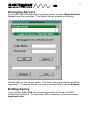
Starting the Sentry Client
To start the Sentry Client, double-click the Sentry icon in the Program
Manager.
Double-click on a server name in the Select Server window. You must
provide a login name and password.
If this is the first time the client is started after installing and loading
smartmon.nlm, then the configuration window will appear. After a UPS
Configuration is saved, the monitoring center window will be the first
window to appear. If the UPS Configuration window appears, see the
chapter titiled UPS Configuration.
To configure the monitoring center window, see the chapter titled
Monitoring Center Configuration.
17
Deleting Sentry
If you wish to remove Sentry from your system, follow the steps required
for your system.
SENTRY SERVER
If you wish to permanently remove Sentry from the file server SYS
volume, follow the steps listed under Unloading, then delete the following
files from the sys:system directory.
del \system\smartmon.nlm <enter>
del \system\current.cfg <enter>
del \system\data.dat <enter>
del \system\dataold.dat <enter>
del \system\event.log <enter>
del \system\eventold.log <enter>
del \ups\netevent.log <enter>
del \system\*.ini <enter>
rd \ups <enter>
You may also have to remove the load commands entered in the
autoexec.ncf file.
SENTRY CLIENT
If you wish to permanently remove Sentry from the Client workstation,
delete the following files and directories. (Be careful when using *.*.)
del \sentry\*.* <enter>
Remove the Sentry directory:
rd \sentry <enter>
Delete the Sentry group folder from the Program Manager, and delete the
group file:
del \windows\sentry.grp <enter>
18
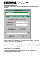
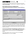
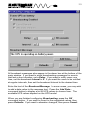
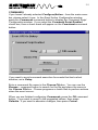
When Sentry is started for the first time, the UPS Configuration window is
displayed. Use this window to setup the software for UPS monitoring.
Select Minuteman or your UPS manufacturer from the Manufacturer
drop-down list box. Next, select the UPS model from the Model dropdown list box.
Next, choose the COM Port to which the UPS interface cable is attached.
Use one of the following COM Port numbers that corresponds to a port
on your system.
COM Port
COM1
COM2
COM3
COM4
Board
0
1
First Available
First Available
Port
0
0
0
1
If your “COM2” is Board 0 Port 1, you can use COM4 to match the first
available Board with Port 1. Sentry will also find the first available
19
hardware type that matches the board and port as listed on the previous
page.
If your UPS supports more than one baud rate setting, select one from
the Baud Rate drop-down list box, and set the baud rate on the UPS.
See your UPS user’s manual for details concerning baud rate
configuration.
Select the Language that will be used to display menu items, field
names, and UPS variables. Also, select the format that will be used to
display dates.
Some UPS models may require you to configure Additional... items. If
the Additional... command button is available, press it to open a
configuration window.
When you finish configuring UPS communications, language, and date
display, press Save to record the values and begin monitoring. If you
would like to abandon all of the changes you made, and exit Sentry,
press Cancel.
If you cancel configuration and you do not currently have a saved
configuration, the Sentry client will exit. To reconfigure UPS
communications, choose Configure|UPS from the menu bar.
20
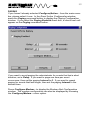
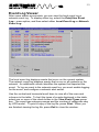
The monitoring center window provides you with a view of current UPS
values. The monitoring center window displays each time Sentry is
started. The reading values and meter graphs are fully configurable and
can display any values provided by the UPS.
If you would like to see other values in the window, changing them is
easy. Configuration is as easy as point and click. You can use color
codes to warn when values are out of an acceptable range.
Configuration is explained in the following sections.
The Alarm box notifies you of software and UPS events.
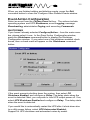
Readings
21
The Readings group allows you to display seven values from the
complete list of UPS values. If you would like to change a reading or the
properties of a reading, just point to the reading and click. The Reading
Configuration window displays.
Pick a value from the Choose Data to Display list box. The values
available will vary depending on the model of UPS. Set the thresholds
and assign colors to the ranges. When the value is displayed in the
Readings box, the background color will reflect the color of the range. If
you also display the value as a meter, the same thresholds are used.
When you finish configuring the reading, press OK. If you wish to clear
the thresholds, press Clear. If you would like to reset the thresholds to
their default values, press Defaults. If you would like to abandon all of
the changes you made, and close the Reading Configuration window,
press Cancel.
22
Meters
The Meters group allows you to graph three values from a list of UPS
values. If you would like to change a meter or the properties of a meter,
just point to the meter and click. The Meter Configuration window
displays.
Pick a value from the Choose Data to Display list box. The values
available will vary depending on the model of UPS. This list may be
different from the readings list, since some values cannot be displayed in
a meter format.
Set the maximum and minimum values for the scale of the graph. Set
the thresholds and assign colors to the ranges. When the graph is
displayed, the background colors will reflect the thresholds. If you also
display the value as a reading, the same thresholds are used.
When you finish configuring the meter, press OK. If you wish to clear the
thresholds, press Clear. If you would like to reset the thresholds to their
suggested values, press Defaults. If you would like to abandon all
changes and close the Meter Configuration window, press Cancel.
23
Changing Servers
To monitor the UPS attached to another server, choose Remote|Select
Server from the menu bar. The Select Server window will display.
Double-click on the server name. The login name and password will be
requested. To rescan the list of servers running Sentry, press Refresh.
Exiting Sentry
If you choose File | Exit, the monitoring center will close, but UPS
monitoring continues. To terminate UPS monitoring, you must unload
smartmon.nlm.
24
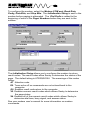
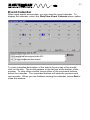
Sentry offers you complete control over UPS system events. The
number of events available varies for different UPSs. The actions
include: operating system and UPS Shutdowns, event Logging,
message Broadcasting, administrator Paging, and executing
Commands. To begin event action configuration, select
Configure|Action....
The Event Action window provides you with a list of events. Select an
event from the Choose Event list box. You can choose any combination
of actions for the event by pressing the action command buttons. Actions
already enabled have a check mark below the name of the action on the
command button. You can also check Popup Main Screen to display
the monitoring center window when an event occurs.
25
In addition to the pre-defined events, you can create your own events.
Press the User Events... command button to display the Configure UserDefined Events window.
User-Defined Event Configuration
User-defined events are based on UPS values. You can configure a
value or range of values to define an event, then use the event to trigger
actions.
Select a UPS value on which your event will be based. Next, select the
criteria that defines when the event occurs. You can use the and or the
or check box to combine comparisons of different UPS values to define
an event. You can also use the and check box to define a finite range of
values for the event.
Give the event a descriptive name and provide an explanation for the
event in the description field. The Event Type is used to group events in
the event log viewer. After you assign an Event Type, click the Add
command button to add the event to the list of Currently Defined
Events.
If you wish to delete an event, click on the event in the Currently
Defined Events list box and press Delete.
26
When you are finished adding and deleting events, press the Exit
command button to close the Configure User-Defined Events window.
Event Action Configuration
Select an event from the Choose Event list box. The actions include:
operating system and UPS Shutdowns, event Logging, message
Broadcasting, administrator Paging, and executing Commands.
SHUTDOWNS
If you haven’t already selected Configure|Action... from the main menu
bar, please select it now. In the Event Action Configuration window,
press the Shutdowns command button to display the Shutdown
Configuration window. If you select one of the shutdown enabled check
boxes, then a check mark will appear on the Shutdowns command
button.
If the event warrants shutting down the system, then select OS
Shutdown Enabled, and configure a Delay. The delay starts when the
event is detected. Next, you may wish to turn UPS output power off. If so,
select UPS Shutdown Enabled and configure a Delay. The delay starts
when the event is detected.
If you would like to automatically restart the UPS after it shuts down due
to a utility power failure, select UPS Autorestart Enabled.
Support for UPS shutdown and autorestart varies by model.
27
WARNING: Shutting down the UPS without first
shutting down the operating system could result in loss
of data. Always add enough time for the operating system to
shut down before shutting down the UPS output.
When you are finished configuring Shutdowns, press the OK command
button. If you want to revert to the suggested values, then press
Defaults. If you want to abandon changes, then press Cancel.
LOGGING
If you haven’t already selected Configure|Action... from the main menu
bar, please select it now. In the Event Action Configuration window,
press the Logging command button to display the Event Logging
Configuration window. If you select the Local Logging Enabled or
Network Logging Enabled check box, a check mark will appear on the
Logging command button.
The local event log records events associated with this system. The
network event log records events for all systems. The master network
event log is configured by selecting Configure|Logging.
28
If you want to avoid logging messages for events that last a short
duration, set a Delay. If you want the event log to show one message
per event occurrence, then set the logging Interval to 0. If you want to
repeat logging for events that last longer, then set the logging Interval to
the desired time.
Enter the text of the Log Message. In some cases, you may wish to add
a current data value to the message text. Press the Add Data...
command button to display a list of UPS values from which to choose.
For example, if the UPS is on battery power, you may want to log the
current input voltage value. The available UPS values depend on the
UPS model.
When you are finished configuring Logging, press the OK command
button. If you want to revert to the suggested values, then press
Defaults. If you want to abandon changes, then press Cancel.
BROADCASTING
If you haven’t already selected Configure|Action... from the main menu
bar, please select it now. In the Event Action Configuration window,
press the Broadcasting command button to display the Broadcasting
Configuration window. If you select the Broadcasting Enabled check
box, a check mark will appear on the Broadcasting command button.
29
All broadcast messages also appear in the alarm box at the bottom of the
main window. If you want to avoid broadcasting messages for events
that last a short duration, set a Delay. If you want to notify users one
time, set the broadcast Interval to 0. If you want the users to be notified
at regular intervals, then set the broadcast Interval to the desired time.
Enter the text of the Broadcast Message. In some cases, you may wish
to add a data value to the message text. Press the Add Data...
command button to display a list of UPS values to choose from. The
available UPS values depend on the UPS model.
When you are finished configuring Broadcasting, press the OK
command button. If you want to revert to the suggested values, then
press Defaults. If you want to abandon changes, then press Cancel.
30
PAGING
If you haven’t already selected Configure|Action... from the main menu
bar, please select it now. In the Event Action Configuration window,
press the Paging command button to display the Paging Configuration
window. If you select the Paging Enabled check box, a check mark will
appear on the Paging command button.
If you want to avoid paging the administrator for events that last a short
duration, set a Delay. If you want to page one time per event
occurrence, then set the paging Interval to 0. If you want to repeat
paging for events that last longer, then set the paging Interval to the
desired time
Press Configure Modem... to display the Modem Alert Configuration
window. The modem configuration can also be displayed by choosing
the Configure|Modem... menu option.
31
To configure the modem, select the Modem COM port, Baud Rate,
Parity, Data Bits, and Stop Bits. The Initialization String is sent to the
modem before paging is attempted. The Dial Prefix is added to the
beginning of each of the Pager Numbers before they are sent to the
modem.
The Initialization String allows you to configure the modem to return
result codes. The result codes allow Sentry to determine the status of the
page. The default string is ATE0Q0V0X4. The meanings of the codes
follow:
AT Attention code
E0 Turns echo off so commands are not echoed back to the
computer
Q0 Enables result code return to the computer
V0 Enables numeric result codes which allows Sentry to determine
the page status
X4 Enables all of the numeric result codes which allows Sentry to
determine dial tone, busy signal, and answer status
See your modem user’s manual for more information on modem
commands.
32
The Dial Prefix should begin with AT, and include any Hayes commands
required to acquire a line and begin dialing the telephone number of the
paging service. The default prefix is ATDT.
The Pager Numbers should include the telephone number for the paging
service, and any required pauses and commands to complete the page.
Up to three Pager Numbers may be configured for all events.
To configure a pager number, press the Add command button. To
modify an existing pager number, click on the number and press Modify.
To delete a pager number from the list, click on the number and press
Delete.
When you are finished with Modem Alert Configuration, press the OK
command button. If you want to abandon changes, then press Cancel.
COMMON MODEM COMMANDS
See your modem user’s manual for a complete list of dial modifiers.
COMMAND
DT
DP
W
,
$
DESCRIPTION
Dial the following number using Tone dialing.
Dial the following number using Pulse dialing.
Wait for Dial tone. It is most often used to wait for the
dial tone of an outside telephone line before processing
the rest of the dial string. The amount of time to wait is
set in the S-Registers of the modem. (S7)
A comma, placed anywhere in the dial string, tells the
modem to pause before processing the rest of the
string. The amount of time to pause is set in the SRegisters of the modem. (S8)
Wait for Bong. It is most often used for calling card
calls, but may be used by a paging service.
Paging Example:
XYZ company has 20 systems running Sentry in one building. You
are configuring Sentry for the third of five systems located in room
122 of the building. To acquire an outside telephone line from your
phone system, you must dial 9 and wait for the dial tone. The
telephone number for the paging service is 1 800 555 1212.
33
The Dial Prefix would be:
ATDT 9 W
If it took the paging service approximately ten seconds to answer and
get ready to accept the paging information, then the paging number
would be:
18005551212,,,,,122 3
When you put the Dial Prefix and the Paging Numbers together,
you create a complete dial string:
ATDT 9 W 18005551212,,,,,122 3
ATDT 9 W causes the modem to dial 9 and wait for the dial tone of
an outside line. 18005551212 is the phone number of the pager.
“,,,,,” causes the modem to wait for approx. 10 seconds. 1223 (122room, 3-computer) is dialed next, and will be displayed on the pager
to identify the computer system that is currently reporting the event.
Dial your pager service to determine what you need to do to configure
paging. Your paging service may vary from the example.
When you are finished configuring Paging, press the OK command
button. If you want to revert to the suggested values, then press
Defaults. If you want to abandon changes, then press Cancel.
EMAIL
Email is not supported.
34
COMMANDS
If you haven’t already selected Configure|Action... from the main menu
bar, please select it now. In the Event Action Configuration window,
press the Commands command button to display the Command Script
Configuration window. If you select the Command Script Enabled
check box, then a check mark will appear on the Commands command
button.
If you want to avoid command execution for events that last a short
duration, set a Delay.
Enter a command file name in the Choose File box. You can use the
Browse... command button to search for the file and place the name in
the Choose File box. Choose programs or batch files to perform actions
when the event occurs.
When you are finished configuring Commands, press the OK command
button. If you want to revert to the suggested values, then press
Defaults. If you want to abandon changes, then press Cancel.
35
Data and Event logs are available for you to track power events and
trends. You can view data in text and graphical form. You can view
events in text form. You can print both data and event files.
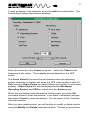
Logging Configuration
Before Sentry begins data logging, you must configure what data is
logged. For convenience, you can also configure the event log from the
same window. To display the Logging Configuration window, select the
Configure|Logging... menu option.
To enable data logging, select the Data Logging Enabled check box.
Press the Select Data... command button to choose a list of UPS values
to log.
Set the data Logging Interval and the Maximum Records for the log
file. When the data log fills, the current data log, data.dat, is moved to
dataold.dat. The data.dat file is reset, and logging continues.
36
Set the Maximum Records for the local event log. When the event log
fills, the current event log, event.log, is moved to eventold.log. The
event.log file is reset, and logging continues.
The Network Alert Server records events for systems across the
network. If you plan to log events to a central network alert server, enter
the system name of the Network Alert Server. You must create a user
account on the Network Alert Server named UPS with a password of
SENTRY. Sentry will use this user account to log entries from each
server. When you create the UPS user account, allow concurrent
connections, no expiration, and do not allow the password to be changed.
Allow the user access only to the \ups directory in the SYS volume.
When you are finished with Logging Configuration, press the OK
command button. If you want to revert to the suggested values, then
press Defaults. If you want to abandon changes, then press Cancel.
Data History Graph
After some data accumulates, you can view a history graph of one of the
data types. To display the graph, select the Data|View Graph... menu
option.
Select the data values from the drop-down list box at the top of the
window. The data associated with the UPS value is graphed. The
37
minimum, maximum, and average values are displayed at the bottom of
the window.
Press the <<< or >>> command buttons to move to the beginning or end
of the data log. Press the < or > command buttons to move back or
forward one full window of data.
Press the Print command button to print a copy of the graph.
You can change the graph’s Y-axis range by using the spin buttons
located on the Y-axis. The X-axis and other properties of the graph can
be changed by pressing the Options... command button. If you press
the Options... command button, the Graph Options window displays.
Select Scatter, Line, or Bar for the Graph Type. Select the Range on
Screen and Hours or Days to define the X-axis range and units.
Depending on Graph Type, choose to display the Average, Minimums,
Maximums, or all three. Average values are graphed in blue.
Minimums are graphed in green. Maximums are graphed in red.
If you would like to view data from an archived data log, enter the File
Name or press to search for the file.
Set the Beginning Date for viewing the graph. The Beginning Date is
the starting point used to determine the maximum, minimum, and
average values. The end point is always the end of the data log.
38
When you are finished with Graph Options, press the OK command
button to close the window. If you want to revert to the suggested values,
then press Defaults. If you want to abandon changes, then press
Cancel to close the window.
When you are finished viewing graphs, press Exit to close the History
Graph window.
Data Log Viewer
After some data accumulates, you can view the data log. To display the
log, select the Data|View Data Log... menu option.
Use the vertical and horizontal scroll bars to view all of the rows and
columns in the table. To print a copy of the log file, press Print. When
you are finished viewing the log file, press Exit to close the window.
39
Event Log Viewer
After some events accumulate, you can view the local event log or
network event log. To display either log, select the Data|View Event
Log... menu option, and then select either Local Event Log or Network
Event Log.
The local event log displays events that occur on the current system.
The network event log displays events that occur on all systems on the
network. An additional column identifies the system that reported the
event. To log an event to the network event log, you must enable logging
for the event, and configure a network alert server.
Use the vertical and horizontal scroll bars to view all of the rows and
columns in the table. To limit the types of events displayed in the table,
select one or more of the check boxes in the View Event Types group
box. The event type category names and the number of categories vary
by UPS model.. To print a copy of the log file, press Print. When you
are finished viewing the log file, press Exit to close the window.
40
Event Calendar
After some events accumulate, you can view the event calendar. To
display the calendar, select the Data|View Event Calendar menu option.
To view a detailed description of the events for any day of the month,
click on the day. The events appear in the list box at the bottom of the
window. To view other months, press either of the command buttons
below the calendar. The command buttons will state the previous and
next months. When you are finished viewing the calendar, press Exit to
close the window.
41
Sentry allows you to schedule operating system and UPS shutdown and
restart, and UPS self tests. To schedule actions, select UPS
Control|Scheduled... from the menu bar.
The Calendar Overview window provides you with monthly calendar of
scheduled actions. A color coded key to the action types is displayed
below the calendar. Actions include: operating system and/or operating
system and UPS Shutdown, UPS Restart, and UPS Self Test.
Availability of operating system and UPS Shutdown, UPS Restart, and
UPS Self-Test depends on UPS model.
To view a detailed description of the actions scheduled for any day of the
month, click on the day. The scheduled actions appear in the list box at
the bottom of the window. To view other months, press either of the
command buttons below the calendar. The command buttons will state
the previous and next months.
42
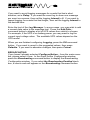
To add an action to the schedule, press the Add command button. The
Scheduling Configuration window displays.
Select an action from the Action group box. Select the Time and the
frequency of the action. The available actions depend on the UPS
model.
The Grace Period is the time interval between when the operating
system shutdown is started, and when the UPS output power is shut off.
Make sure the Grace Period you select allows your system to shut down
properly. Grace Period will only be displayed when Shutdown,
Operating System, and UPS are selected in the Action group.
When you are finished with Scheduling Configuration, press the OK
command button to close the window. If you want to abandon changes,
then press Cancel to close the window. You will return to the Calendar
Overview window.
After you have added events, you will be able to modify or delete events
using the Modify and Delete command buttons. Choose an event from
43
the list box, and press the appropriate command button. If you choose to
Modify an event, then the Scheduling Configuration window displays.
When you are finished with the Calendar Overview window, press the OK
command button to close the window. If you want to abandon changes,
then press Cancel to close the window.
44
UPS control options are special commands sent to the UPS. These
commands are dependent on the model of UPS. To display the
Additional UPS Control Options window, select the UPS Control|Control
Options... menu option.
To send a command to the UPS, click on a command in the Control
Commands list box, and select Execute Command. If the control
command requires data to be sent with the command, a data entry
window will appear. Control Commands vary for different UPS models.
When you are finished sending commands to the UPS, press the Exit
command button to close the window.
45
We have made every effort to ensure an easy and straight forward Sentry
installation. If you should experience problems or unexpected results
during the installation or execution, please verify your system setup and
configuration using the following checklist:
• Positively identify the serial port to which the UPS interface cable is
connected. (Consult computer and/or operating system
documentation if necessary.) Note the Hex address and IRQ number
for each serial port and identify AIO Board & Port values.
• Verify that no other hardware or software is using/accessing this
serial port, including your mouse. Sentry requires a serial port
dedicated to monitoring the UPS.
• Verify that you are using the UPS interface cable supplied with the
Sentry software and that it is securely connected to the serial port.
• Verify that the other end of the supplied cable is securely attached to
the UPS interface port. This end should not require any adapters.
• During installation, make sure you are logged in to the target server
as Supervisor or Admin.
Common Problems and Solutions
Problems
When loading
my hardware
specific AIO
driver, it
cannot find the
serial port or
assigns a very
high number to
the board or
port value.
Solutions
Are your AIO drivers loaded properly? You may have to
load the hardware specific driver more than once to find
all serial ports.
A conflict may occur when other hardware devices or
software. Hardware conflicts will appear in DOS as well
as Novell, and may be easier to identify (address/IRQ).
Software conflicts will only appear in Novell, and may
occur with other applications that provide port services,
including pserver.
Make sure the serial port is enabled. Make sure the
port is operational, by performing another test on it,
such as attaching a modem and attempting to dial out.
46
Problems
During
installation or
startup of
Sentry, you get
the UPS
communications failure
message
The modem
did not page
the administrator after a
power failure
or other event.
Solutions
Make sure the cable is plugged into the UPS and the
computer.
Make sure you have correctly identified the serial ports.
You may have connected the cable to the wrong port.
Ports may be mislabeled.
Make sure the serial port is enabled. Check your
computer’s jumpers and/or BIOS.
Make sure the port is operational, by performing
another test on it, such as attaching a modem and
attempting to dial out.
A conflict may occur with other hardware devices or
software. Is the port already in use?
If the UPS is charged and seems to be operating
properly, and all other procedures have been followed,
you will have to contact technical support.
Check the phone line to make sure it is attached to the
modem and wall outlet.
Check the phone line to make sure that it is working
and that there is a dialtone.
Make sure you have correctly identified the serial ports.
Ports may be mislabeled.
Make sure the serial port is enabled.
Make sure the port is operational, by performing
another test on it, such as attaching a terminal and
attempting to Login.
A conflict may occur with other hardware deevices or
software. Is the port already in use?
Test your pager dial string to verify that it works. You
can use the simulated power failure event.
NOTE: Release notes are available on our
World-Wide-Web site. If you don’t have access to the
World-Wide-Web, contact our technical support department.
See Placing a Technical Support Call for more information.
47
In order to diagnose the problem you are having, our technicians need
the following information from you:
Installation Site:
Company Name: _____________________________________
Address:____________________________________________
City: _______________________________________________
State: ______________________________________________
ZIP code: ___________________________________________
Installation Site Contact:
Full Name: __________________________________________
Phone Number: ______________________________________
Fax Number: ________________________________________
you are a consultant,
Consultant Name: ____________________________________
Phone Number: ______________________________________
Fax Number: ________________________________________
Computer System:
Operating System Version: _____________________________
System Manufacturer: _________________________________
System Model Number: ________________________________
Type of Serial Port Connector
(How many pins, male or female, etc.): ____________________
___________________________________________________
Address of the Port: ___________________________________
48
UPS:
Model Number: ______________________________________
Type of Port Connector (How many pins, male or female, etc.):_
___________________________________________________
Sentry Configuration:
Cable’s Part Number (From tag on end of cable): _______________
Are any adapters connected to the cable?_____________________
If yes, what type? _____________________________________
What are the symptoms?
Technical Support
Have the information listed above ready.
You can reach us by calling:
Para Systems, Inc.
1455 LeMay Dr.
Carrollton, TX 75007
Phone: (972) 446-7363
Fax: (972) 446-9011
E-Mail: [email protected]
QuickFax Info System: 1-800-263-3933
Internet: www.minuteman-ups.com