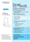
1
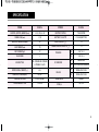
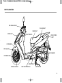
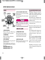
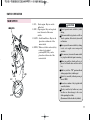
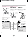
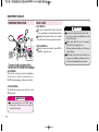
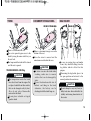
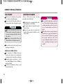
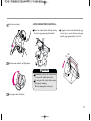
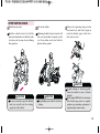
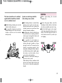
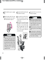
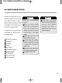
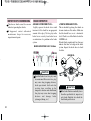
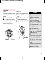
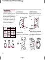
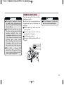
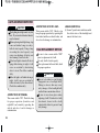
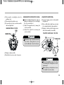
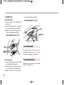
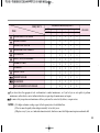
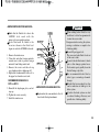
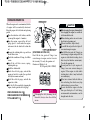
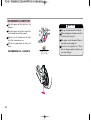
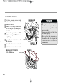
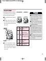
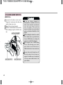
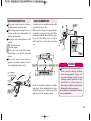
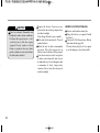
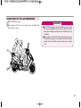
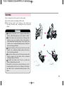
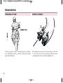
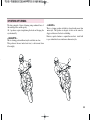
OWNER S MANUAL
IMPORTANT NOTICE
●
WELCOME
Thank you for purchasing an Daelim vehicle. We hope you enjoy safe riding.
●
OPERATOR AND PASSENGER
This motorcycle is designed to carry the operator and one passenger.
WARNING
Attempting to change the pre-set maximum speed may cause danger and will void the Daelim warranty.
●
ON-ROAD USE
This motorcycle is designed to be used only on the road.
●
READ THIS OWNER'S MANUAL CAREFULLY
Pay special attention to statements preceded by the following words:
WARNING
Indicates a strong possibility of severe personal injury or death if instructions are not followed.
CAUTION
Indicates a possibility of personal injury or equipment damage if instructions are not followed.
NOTE
Gives helpful information.
This manual is an important and integral part of your vehicle. keep it with your vehicle at all times, even though your vehicle is resold.
2
CONTENTS
SPECIFICATION
OPERATION INSTRUCTION
SAFETY PRECAUTIONS
3
EQUIPMENT USAGE
14
4
STEERING STEM LOCK
14
4
SEAT LOCK
14
PRIOR TO STARTING VEHICLE
5
TRUNK
15
OPERATION
5
DOCUMENT STORAGE AREA
15
CORRECT ATTIRE
6
BAG HOLDER
15
CARGO
6
MODIFICATION
CORRECT DRIVING OPERATION
16
7
STARTING THE ENGINE
16
ATTACHMENT
7
IF ENGINE CANNOT BE STARTED
18
MUFFLER
7
AFTER STARTING ENGINE
19
8
PROPER DRIVING METHODS
20
STOPPING
21
PARTS LOCATION
METER READING AND USAGE
METER
10
10
SELF INSPECTIONS BEFORE OPERATION
23
24
INDICATOR LAMPS
10
INSPECTION OF CONCENED AREA
SIDE STAND LAMP
10
BRAKE INSPECTION
24
MALFUNCTION INDICATOR LAMP
10
FUEL CHECK
25
11
TIRE INSPECTION
26
11
ENGINE OIL LEVEL CHECK
27
START BUTTON
12
LIGHTS AND WINKER INSPECTION
28
HEADLIGHT
12
BULB REPLACEMENT METHOD
28
WINKER SWITCH
13
REAR VIEW MIRROR
30
HORN BUTTON
13
FUEL LEAK INSPECTION
30
PASSING SWITCH
13
SWITCH OPERATION
MAIN SWITCH
1
MAINTENANCE
2
31
SAFE DRIVING
49
MAINTENANCE SCHEDULE
32
PREPARATION BEFORE DRIVING
49
MAINTENANCE PRECAUTIONS
34
DRIVING METHOD
50
BRAKES
34
DRIVING POSITION
50
BRAKE HOSE, PIPE LEAKAGE, DAMAGE, ASSEMBLY STATE
36
TAKING POSE OF FELLOW PASSENGER
51
BRAKE PAD WEAR
36
PRECAUTION WHEN DRIVING
52
CHANGING ENGINE OIL
37
STARTING
53
TRANSMISSION OIL INSPECTION
38
TURNING METHOD
54
WHEEL REMOVAL
39
PRINCIPLE OF TURN
54
CHANGING COOLING WATER
41
EFFECT OF SPEED
54
SPARK PLUG
41
3 POSITIONS OF TURNING
55
BATTERY INSPECTION
42
TURNING METHOD
56
FUSE REPLACEMENT
43
PRECAUTION WHEN TURNING
57
COUPLER CONNECTION
44
AIR CLEANER ELEMENT INSPECTION
44
BASIC PRINCIPLE OF BRAKE(FRICTION FORCE)
58
SIDE STAND INSPECTION
45
RESTRAINT OF BRAKING EFFECT (INERTIA)
58
CABLE RUBBER PART
45
BRAKING METHOD
59
CLEANING
46
COMPARISION OF BRAKING DISTANCE
59
GENERAL CLEANING / IMPORTANT
47
IMPACT WHEN COLLISION
59
STORAGE GUIDE
47
FRAME AND ENGINE NUMBER
48
BRAKING METHOD
WIRING DIAGRAM
58
60
SPECIFICATION
ITEM
DATA
ITEM
DATA
LENGTH WIDTH HEIGHT(mm)
1.965 702 1.120
IGNITION SYSTEM
TRANSISTOR
WHEEL BASE(mm)
1.350
BATTERY CAPACITY
12V10AH(MF TYPE)
GROUND CLEARANCE(mm)
126
FUEL CAPACITY( )
9.6
SEAT HEIGHT(mm)
770
RESERVE FUEL CAPACITY( )
2.2
DRY WEIGHT(kgf)
127
PASSENGER
2
ENGINE TYPE
OIL- COOLED/AIR- COOLED
4 STROKE 4VALVE
PISTON DISPLACEMENT(cc)
TIRE SIZE
SUSPENSION
124.9
BRAKE
FR.
120 / 70 - 13
RR.
130 / 60 - 13
FR.
TELESCOPIC
RR.
UNIT SWING OIL DAMPER
FR.
HYDRAULIC DISK
RR.
HYDRAULIC DISK
BORE AND STROKE(mm)
56 50.7
STARTING SYSTEM
START MOTOR
SPARK PLUG
CR8EH-9
TRANSMISSION TYPE
V - MATIC
FUSE(A)
30A, 15A
3
OPERATION INSTRUCTION
This manual describes matters pertaining to correct operation,
safe operation and simple maintenance of the vehicle you
purchased.
To ensure more comfortable and safer operation, make sure to
read this manual carefully prior to operation.
The photographs and drawings shown in this manual may
differ from those of actual vehicles due to changes in vehicle
specifications and modifications made.
This vehicle is designed for 2 riders including the operator.
CAUTION
Do not use polluted gasoline.
Otherwise, it cause rust inside the fuel tank, and
close the supply of fuel to the injector, leading to an
improper engine starting or may cause serious
damage to an engine.
Do use genuine oil.
Then it will protect and extend vehicle life.
Warranty does not apply to the motorcycles used in
competitions or competitive trials. No motorcycle
part may be tampered with, altered, or replaced with
parts other than original Daelim spare parts during
the warranty periody.
As far as any defect caused by contaminated gasoline
or oil, the warranty will be automatically invalidated.
4
SAFETY PRECAUTIONS
Careful driving and the wearing of proper attire and safety
equipment are the most important factors in the safe operation
of the scooter. Please obey traffic regulations and do not be
hurried and careless.
Many new vehicle owners operate their newly purchased
vehicles with great care and attention to safety factors.
However, after becoming accustomed to the operations are
often discarded, which can lead to accidents. Please don't let
this happen to you and always approach the operation of your
vehicle with the safety considerations needed.
When operating the vehicle, always keep in mind and obey the
notes of precaution printed on the Safety Precaution Label
attached to the vehicle.
Be sure to wear helmet at all time.
Be sure to put on gloves at all time.
Always respect speed limits where these are posted.
However, always adjust your speed to the visibility,
road and traffic conditions you are riding in.
Beware of muffler affer driving as it is still hot to be
burnt. Especially never children touch on it.
For safety, do not change, alteration or modification
the vehicle.
Regularly conduct specified maintenance inspections.
<Maintenance Inspection Points>
Brakes, Tires, Oil, Lights, Horn, Instruments
PRIOR TO STARTING VEHICLE
Read user's manual carefully.
Conduct maintenance checks prior to operation.
Always maintain vehicle in clean status and carry out specified
maintenance checks.
Make sure to stop engine and stay away from fire when
fueling.
Exhaust gas contains harmful substance such as carbon
monoxide. Start engine in well-ventilated places.
OPERATION
Operators should naturally fix bodies to keep smooth driving.
Please check whether or not you are unnaturally strained and
strung up.
Driving pose has a great influence on safe operation.
Please always maintain the center of your body in the middle of
seat. Especially do not sit at the rear seat because it may lessen
the weight of front wheel and cause trembling steering wheel.
Always hold the handlebars firmly with both hands whiling
driving, The pillion passenger should always hold on to the
suitable grab handles at the sides of the seat with both hands.
otherwise, it cause severe injury or death.
When wanting to turn, slightly lean to body toward the
direction of the turn. It is unsafe if the body is not moved in
union with the vehicle.
Curvy roads and poor, unpaved roads constantly change in
surface quality. Driving on these roads can be unsafe if certain
safety precautions are not followed.
In order to safely drive through these driving conditions,
anticipate coming road conditions, slow down to at least half
the normal speed, and relax your shoulders and wrists while
securely holding the handles.
5
CARGO
CORRECT ATTIRE
Be sure to wear helmet and gloves at all time for seafty.
Wear shirts or jackets with tight in the wheel driving.
Otherwise it can be caught in the wheel to cause serious
damage by overturn of vehicle.
Many automobile/motorcycle accidents happen because the
automobile driver does not “Look” the motorcyclist.
- Wear bright or reflective clothing.
- Don’t ride in another motorist’s “blind spot”.
Be sure to wear dress to catch an eye to avoid any crash from
behind.
When carrying cargo, you must keep in mind that operating the
motorcycle, especially when turning, will be different.
Make sure not to overload the motorcycle with goods as this
can make the motorcycle unstable during operation.
WARNING
Be sure you and your passenger always wear a helmet,
eye protection and other protective apparel when you ride.
Not wearing a helmet increases the chance of serious
injury or death in a crash.
CAUTION
Pay attention not to overload goods and fasten it tightly
whiling driving.
Do not place articles between the frame body cover and
engine as it is hot to be burnt.
Do not place kind of cloth materials nearby oil tank cap.
If the hole in oil tank cap is clogged, oil will not flow freely
into the engine which can cause severely engine damage.
Do not attach large or heavy items (such as a sleeping bag
or tent) to the handle bars, fork, or fender. Unstable
handling or slow steering response may result.
6
MUFFLER
MODIFICATION
Modification of vehicle structure of function deteriorates
manipulatability or causes exhaust noise to become louder
shortening the vehicle life. These modifications are not only
prohibited by law but also are the acts harmful to other people.
Modifications are not covered by warranty.
CAUTION
As far as any defect caused by modifications, the
warranty will be automatically invalidated.
Pay particular attention to fellow passenger so that he/she can
prevent getting burnt by the hot muffler during travel.
CAUTION
Beware of muffler after driving as it is still hot to be
burnt. Especially never children touch on it. And pay
attention to park where pedestrian zoon.
If haystack or vinyl is stuck to the muffler, it might be
fired.
ATTACHMENT
Except designated attachment by DAELIM MOTOR CO.,
LTD., don't attach any extra lighting device, because it may
cause an early discharging of battery.
Carefully inspect the accessory to make sure it does not
obscure any lights, reduce ground clearance and banking angle,
or limit suspension travel, steering travel or control operation.
Do not add electrical equipment that will exceed the
motorcycle’s electrical system capacity. A blown fuse could
cause a dangerous loss of lights or engine power.
WARNING
Improper accessories or modifications can cause a
crash in which you can be seriously hurt or killed.
Follow all instructions in this manual regarding
accessories and modification.
7
PARTS LOCATION
REAR VIEW MIRROR
BATTERY
FR. BRAKE LEVER
BAG HOLDER
MUFFLER
REAR BRAKE DISK
8
TIRE
PILLION STEP
PARTS LOCATION
RR. BRAKE LEVER
PILLION SEAT
MAIN SEAT
HEADLIGHT
FUEL TANK LID
REAR COMBI.
LIGHT
FR. FENDER
FR. CUSHION
AIR CLEANER
FR. BRAKE DISK
SIDE STAND
BRAKE CALIPER
SIDE STAND SWITCH
MAIN STAND
9
METER READING AND USAGE
METER
MIL<MALFUNCTION INDICATION LAMP>
<FUEL WARNING INDICATOR>
When the fuel is low, the fuel warning
indicator turns on.
When this happens, fill the fuel tank with
the gasoline.
WARNING
To avoid running out of fuel, it might
cause severe injury due to engine
abruptly stop.
INDICATOR LAMPS
<SPEEDOMETER>
Indicates driving speed. Maintain legal
speed limits to ensure safe operation.
<ODOMETER>
Indicates total distance in kilometers
travelled by the vehicle.
10
<WINKER INDICATOR>
When the winker switch is operated,
the winker indicator flashes in union
with the flashing of the turn signals.
<FUEL METER>
<SIDE STAND LAMP>
The fuel meter indicates the gasoline level
inside the fuel tank.
Gasoline should be put in the fuel tank as
soon as possible if the needle is resting in
the red area.
FUEL TANK CAPACITY : 9.6
RESERVIOR CAPACITY : 2.2
When the side-stand is down, the engine
will stop with side-stand lamp on.
EMS(Engine Management System)is
equipped with a self-diagnosis function in
order to ensure that the engine control
system is operation normally.
If this function detects a malfunction in the
system, the malfunction indicator lamp
immediately operates.
It gives the rider that malfunction has
occurred in the system.
Normally, the malfunction indicator lamp
illuminates for 3 seconds when the main key is
turned on.
If the malfunction indicator lamp does not
come on under these conditions, the
malfunction indicator lamp may be
defective.
After 3 seconds, the malfunction indicator
lamp off automatically. However, the MIL
blinks continuously, check the EMS
system. If you are not able to check the
EMS system, contact your daelim dealers.
The EMS takes fail-safe function, it enables
to drive only temporary by starting even on
conditioned.
SWITCH OPERATION
MAIN SWITCH
1. ON.... Starts engine. Key can not be
pulled out.
2. OFF....Stops engine. Key can be placed
in or taken out of the main
switch.
3. LOCK....Locks handle bars. Key can be
placed in or taken out of the
main switch.
4. OPEN....When seat lock is released, key
returns to its original
position(OFF). Key can be
placed in or taken out of the
main switch.
CAUTION
Do not operate main switch key while
driving.
If the main switch key is placed on Off or
Lock position, all electrical system will
not function.
Never operate the main switch key during
travel as it might cause unexpected
accidents.
If it is necessary to remove the main switch
key, stop the vehicle first prior to removing.
When you park the vehicle and leave it,
please lock handle bars and take out the
key.
If the key is left in ON position without
starting engine, battery is discharged.
ON
OFF
Rotate key smoothly without pressing to
turn to OPEN.
Do not use a number of keys together with
a metal key holder.
LOCK
The keys and the key holder may cause
scratches or other damage to the cover
while operating the vehicle.
(Recommend cloth or leather key holders)
11
START BUTTON
HEADLIGHT
<TURNING ON HEADLIGHT>
<DIMMER SWITCH>
Put main switch key in “ON” position and
turn on headlight switch.
High beam or low beam can be operated
by the use of dimmer switch.
The engine is started pressing this button
when pressed in a state where the main
switch key is placed to an ON position
and the brake lever is pulled.
CAUTION
The engine will not start if the brake
lever is not grab.
Do not hold the brake lever and
pull the throttle grip when the
engine was started. It may damage
the engine.
HIGH BEAM
SWITCH POSITION
(H)
Headlight, taillight,
position lamp and
meter lights on.
(P)
Position lamp, taillight,
and meter lights on.
(OFF)
12
FUNCTION
Light turned off.
D(HI)
...... used when needing extra
light.
LOW BEAM
...... used when other vehicles
D(LO)
are present, in the city, etc.
CAUTION
Use the high beam only in the
suburban road or when the usage of
the high beam not hinder the safe
driving of the car ahead.
WINKER SWITCH
If this switch is turned on when the main
switch is in an ON position, the winker will
operate.
(R)....used when making a right turn.
(L)....used when making a left turn.
HORN BUTTON
The horn is sounded if the horn button is
pressed when the main switch is in an ON
position.
HAZARD SWITCH
The winker and the winker indicator lamp
will operate at the same time if the hazard
switch is pressed when the main switch is
on.
CAUTION
The winker switch does not automatically turn back to its original
position after completing the turn.
Please set the switch back to its
center position after turning.
13
EQUIPMENT USAGE
STEERING STEM LOCK
SEAT LOCK
<LOCKING>
The seat automatically locks when the
seat is pushed in its downward position,
Lightly pull upward on the seat to make
sure the seat has been properly locked.
<UNLOCKING>
Turn the main switch key from OFF to
OPEN to open the seat.
<LOCKING>
To lock the steering, turn the handlebars
all the way to the left, turn the key to
LOCK while pushing in. Remove the key.
<UNLOCKING>
To unlock the steering, turn the key to the
OFF position.
WARNING
Do not turn the key to LOCK while
riding the vehicle; loss of vehicle
control will result.
14
CAUTION
As the seat automatically locks, take
special care not to accidently leave the
key in the trunk.
Make sure that the seat is securely
locked after closing the seat.
Driving with unlocked seat lock may
cause danger.
When the seat lock is out of order, do
not operate it further and inspect it in
the closest authorized repair center.
TRUNK
DOCUMENT STORAGE AREA
There is a trunk under the seat.
The seat is opened to gain access to the
trunk by using the main switch key on
the seat lock.
The lamp inside the trunk will be turned
on if the seat is opened.
TRUNK MAXIMUM LOAD:10kg
CAUTION
The temperature inside the trunk
rises due to heat from the engine. Do
not place foodstuffs and other articles
that can be damaged easily by heat.
Also do not place flamm-able
materials in the trunk.
Do not place valuable or fragile
goods in trunk.
There is a document storage area on the
bottom of the seat.
Store the owner’s manual and the
maintenance notebook in this area.
CAUTION
As water can enter the trunk when
washing, make sure to remove
articles that can be damaged by
water.
Do not load uncloseable size of
helmet and thing in the tunk,
otherwise, the battery can be
discharged with the trunk lamp on.
BAG HOLDER
For ease in carrying bags and similar
items, they should be hung from the
bag holder which is fitted for this
purpose.
When using the bag holder, place it in
the open position and return it to the
normal position when not in use.
CAUTION
Do not attempt to carry very heavy or
bulky loads since this would affect the
stability and steering characteristics of
the scooter.
15
CORRECT DRIVING OPERATION
BAG HOLDER
Make sure to check the oil, gasoline,
etc., before starting the engine.
Please ensure that the main stand is in a
down position when starting the engine.
CAUTION
Make sure that the rear wheel is
locked when starting the engine to
prevent an unexpected quick start of
the vehicle.
Locking is not possible if the rear
wheel brake is not adjusted correctly.
Drive with care for both safety reasons
and longer vehicle life.
<BREAK-IN OPERATION>
For 1 month (or 1,000km) after purchasing the vehicle, drive moderately
avoiding fast starts and fast acceleration.
Maintain engine revolution at a level
less than 6,000rpm for first 1,000km to
break-in vehicle.
If vehicle is broken-in as above, it will
extend vehicle life.
16
STARTING THE ENGINE
Always follow the proper starting
procedure described below.
This motorcycle is equipped with a side
stand ignition cut-off system.
The engine cannot be started if the side
stand is down.
Always be ensure that you operate the
engine starting controls with the scooter
on its stand.
WARNING
Never run the engine in an enclosed
area. The exhaust contains poisonous
carbon monoxide gas that can cause
loss of consciousness and lead to
death.
While the scooter is on its stand you
should never apply full throttle:if
the rear wheel touches the ground
the scooter would set off at full
speed. (Remember that the scooter
has a centrifugal automatic speed
control)
Lock the rear wheel.
<USING THE ELECTRIC START(CELL)>
Press the starter button without rotating
the starter grip (opening the throttle).
If engine is not started with throttle grip
closed, press starter button and open
throttle grip approximately 1/8 to 1/4.
1/8
1/4
Turn the main switch to an ON position.
CAUTION
Immediately release the starter button
as soon as the vehicle has started.
Do not press the starter button when
the engine is running.
This can damage the start motor.
Start engine with cell button.
17
IF ENGINE CANNOT BE STARTED
It is possible that starting will be more
difficult if the vehicle has not been used
for a long period of time or if the fuel
hole is plugged up(starting problems
even when there is sufficient fuel in the
fuel tank may be an indication of a
plugged fuel hole).
When this happens, do not rotate the
throttle grip and try the starter button a
few times.
CAUTION
Do not keep the statter button pressed for
more than 5 seconds at a time. Release the
starter button for approximately 10
seconds before pressing it again.
18
When the engine is cold morning or
winter or the vehicle has not been used
for a long period of time, let the engine
idle for a short period allow the engine
to warm up.
CAUTION
Keep holding rear brake until start.
Exhaust has contains harmful substance such as carbon monoxide.
Start engine in well-ventilated places.
If engine cannot be started or vehicle does
not move, check the followings.
Is there fuel in fuel tank?
Are you operating in accordance with
the instructions given in owner’s
manual?
Is fuse not cut?
Is starter motor running?
If starter motor is not running due to
battery consumption, charge the battery.
If the MIL blinks continously when the
main key is on, contact Daelim dealer.
AFTER STARTING ENGINE
Fold the main stand.
Get on the vehicle.
Push the vehicle forward to fold the
main stand and make sure that the brake
lever does not become released during
this operation.
Mounting should be done from the left
side, and you should sit squarely on the
seat. Leave either one foot or both feet
planted on the ground
Release the squeezing tension on the
rear brake lever and slowly begin to
rotate the throttle grip to allow for a
slow and easy start.
CAUTION
CAUTION
Do not excessively open the throttle
until you actually start the driving
operation of the vehicle.
CAUTION
Keep holding rear brake lever before
starting.
A quick rotating of throttle grip will
cause the vehicle to move forward
abruptly.
If the engine RPM will not turn down
after throttle grip return to original
position, stop operating and inspect it
registered repair center nearby.
19
PROPER DRIVING METHODS
Before entering traffic, use the correct
turn signal to foreward other drivers of
your intentions.
Speed is controlled by the operation of
the throttle grip.
If the throttle grip is rotated........
The speed of the vehicle increases.
Please rotate the throttle grip slowly.
When climbing a hill, the throttle grip
need to be rotated further to give the
vehicle more power.
Work the front and rear brakes
together.
Allow the throttle grip to rotate back to
its beginning position and then squeeze
the brake levers.
If is best to operate the brakes by first
lightly squeezing the brake levers and
then changing to a more firm squeeze.
If the throttle grip is allowed to
rotate back........
Speed decreases. This can be done
slowly or quickly, depending on how
quickly you need to decelerate.
CAUTION
If only one of the brakes is used, it is
possible for the vehicle to sliding.
20
STOPPING
The brakes should never be suddenly
applied and the handle bars should
never be suddenly turned.
Sudden braking or turning can cause the
vehicle to slide and tip over.
It is especially dangerous to perform
sudden braking on wet roads or in rainy
weather as the tires can lose traction
and slip easily.
Special care in driving should be
taken during rainy weather.
More braking distance is needed when
driving on wet roads or in the rain.
Reduce speed and be sure to initiate the
braking operation sooner than when
driving in normal conditions.
On downgrades, allow the throttle grip
to rotate back to its initial position to
reduce speed, and apply the brakes and
drive slowly down the hill.
It is possible for the brakes to
temporarily lose operative ability after
driving through a puddle or when
driving in the rain. To ensure that the
brakes are operating properly, slow
down(after checking for other vehicles)
and while driving slowly, lightly apply
the brakes to rid the brakes of any
excess water and to dry them.
Be extremely careful when driving in
the snow or on icy roads.
When driving in these conditions, both
the tires lose much of their traction and
the rear tire can slip when opening the
throttle.
When approaching the desired
stopping area.
Activate the proper winker, and after
checking for other vehicles, slowly turn
into the area in which you want to stop.
Allow the throttle grip to rotate completely back and apply the front and rear
brakes. The brake light will shine to
alert vehicles in back of you that you
are stopping.
21
After the vehicle has come to a complete
stop.
Dismount on the left side and lower the
main stand on a flat surface.
Return the winker switch to the center
position and turn the main switch to
OFF. This will turn the engine off.
Be sure to park in an area that is free of
traffic. Also, the vehicle can tip over if
the main stand is not placed on a stable
and flat surface.
The main stand is lowered by grasping
the handle bars with the left hand,
holding the rear carrier with the right
hand, and stepping firmly on the stand
with the right foot. In this position, lift
the rear carrier upward, which will
secure the main stand.
CAUTION
Do not rotate the main switch key
while driving. If the main switch is
turned to an OFF or LOCK position,
the electrical system will not operate.
Operating the main switch key while
driving can be very hazardous. Only
turn the main switch key to OFF or
LOCK position after completing
stopping the vehicle.
22
To prevent theft, be sure to lock the
steering when parking.
CAUTION
Park in a safe area that will not block
traffic. When you parked the vehicle
after driving, make sure foot the
vehicle beyond man’s reach because
engine and muffler are still hot.
Park the motorcycle on firm, level
ground to prevent it from failling
over.
If you must park on a slight incline,
aim the front of the motorcycle uphill
to reduce the possibility of rolling off
the side stand or overturning.
SELF INSPECTIONS BEFORE OPERATION
Self inspect the vehicle and have regular
maintenance inspections for increased
safety and the prevention of accidents.
Regular maintenance inspections should
be performed even if the vehicle has not
been used for a long period of time.
Self inspections before operation should
be performed on a daily basis prior to
operating the vehicle.
Inspections of concerned Area
Brake inspection
Tire inspection
Fuel check
Engine oil check
Lights and winker inspection
Back mirror inspection
Fuel leak inspection
License plate inspection
Throttle grip inspection.
CAUTION
Observe safety rules when conducting
inspections.
Exhaust gas contains harmful
substance such as carbon mono-xide.
Do not carry out inspections on
vehicle in closed places, or in poorly
ventilated places, with engine
running.
Conduct inspections on flat, solid
ground with the stand erected.
Be careful of burns when conducting
inspections immediately after engine
is stopped because the engine and
muffler are hot.
Stop engine and remove the key prior
to the vehicle maintenance service.
Use appropriate types of tools.
CAUTION
If you are unable to correct trouble
even after you make adjustment or
correction, contact authorized
maintenance shops, dealers or
designated repair shops for necessary
inspection and repairs.
23
INSPECTION OF CONCENED AREA
Check areas which caused for concern
when last operating the vehicle.
If happened, contact authorized
maintenance shops for necessary
inspection and repairs.
BRAKE INSPECTION
<BRAKE LEVER FREE PLAY>
<CHECK OF BRAKE FLUID>
Lightly squeeze the brake levers until
tension is felt to check for an appropriate
amount of free play. No free play in the
brake levers or overly loose brake levers
are indication of a problem in the brake
system.
This is checked by placing the vehicle on
its main stand on a flat surface. Make sure
that the handle bars are at a horizontal
level. Check to see if the fluid is below the
LOWER level.
If brake fluid is significantly low, this may
indicate that there is leakage in the brake
system. Inspect the brake hose to check
for leaks.
BRAKE LEVER FREE PLAY: 10~20mm
CAUTION
Specified brake lever free play must
be maintained. Excessive free play
may cause long stopping distance,
brake operational fault and slow
reacting time resulting in the
dangerous situation and insufficient
free play may cause short stopping
distance and damage brake
system(pad, lining, etc.)
24
CAUTION
If the brake fluid is remarkably lower
than the specified level, inspect not
only brake fluid but also check the
front brake pad for wear.
FUEL CHECK
<CHECK>
Check gasoline to see if there is a sufficient
amount of gasoline to reach your
destination.
Place the main switch to “ON” position.
If the fuel meter needle indicates E
mark (red portion), fill fuel tank with
gasoline as soon as possible.
RESERVE FUEL CAPACITY : 2.2
<REFUELING>
Open the key cover on fuel tank cap,
and turn the key clockwise to remove
the cap.
Fill the tank with gasoline until it
reaches the bottom of the level plate.
Press the cap firmly, and pull out the
main key.
CAUTION
Gasoline is extremely flammable and
is explosive under certain conditions.
Refuel in a well-ventilated area.
Make sure to stop engine and stay
away from fire when refueling.
Do not fill gasoline past the level
plate. Gasoline may leak out of the
fuel tank when replacing the fuel
tank cap if too much gasoline is put
in the fuel tank.
Don’t fill low grade gasoline.
Using it can cause damage (bending,
getting worn, etc.) to combustion
chamber and parts of fuel.
Do not close the fuel cap with
excessive strength. It may cause the
damage of the cap and the rubber
packing resulting in the leak of fuel
and may cause fire in case of
electrical short or the overturn of the
vehicle.
Avoid repeated or prolonged contact
with skin or breathing of vapor.
Keep out of reach of children.
25
TIRE INSPECTION
<AIR PRESSURE CHECK>
<CRACKS/DAMAGE>
<FOREIGN MATERIALS>
Check for an appropriate level of air
pressure by examining how the tire sits on
the ground. If you notice any abnormalities in
the shape of the tire with regard to the
area contacting the ground, use a tire
gauge to check tire pressure and adjust the
tire pressure to the appropriate level.
Check tire tread and sides for cracks and
damage.
Check tire tread and sides for nails, rocks,
etc. That might have become wedged in
the tire.
SIZE
120/70-12
130/70-12
1.75
FRONT
WITH ONE
PERSON REAR 2.00
FRONT
REAR
TIRE
PRESSURE
(kgf/ ) WITH TWO FRONT
PERSON REAR
26
2.25
2.25
<TREAD DEPTH>
<ABNORMAL WEAR>
Check tire tread for signs of abnormal
wear.
Check the wear indicator (wear limit
marking) to see if there is an insufficient
amount of tread remaining.
If the indicators are visible, replace tire
with a new one.
ENGINE OIL LEVEL CHECK
CAUTION
If air pressure is inadequate or if there
are cracks, damage or abnormal wear
on tires, it may cause trembling steering
wheel and flat tire.
Insufficient air pressure may cause
the heavy steering wheel making
handling difficult, fuel over
consumption and the excessive wear
of tire outer area and excessive air
pressure may cause easier
wheel handling and lower fuel
consumption. But it may also cause
the excessive wear of tire center area.
Check the engine oil level each day before
riding the motorcycle.
The oil level must be maintained between
the upper and lower level marks on the
sight-glass
Stand the motorcycle on the main stand
on level ground.
Start the engine and let it idle for
approximately 2~3 minutes.
Check the engine oil level.
If required, add the specified oil. Do not
overfill.
CAUTION
To avoid running out of engine oil, it
may cause serious engine damaged.
UPPER LEVE
MIDDLE LEV
This vehicle is equipped with
tubeless tires. If you have flat tires,
please contact authorised maintenance shops for inspection.
LOWER LEVE
27
LIGHTS AND WINKER INSPECTION
CAUTION
The lighting head light emits very hot
heat. If you touch with naked hand, it
may be burned.
When replacing head light lamp, stop
lame and winker lamp, use only a
bulb of rated capacity. Using a lamp
exceeding the rated capacity can
cause over-discharge of battery and
wire burning. It can lead a fire.
If the head light is turned off due to
aging while driving at night, it will
cause an accident by obstructing
driver’s view. Check the condition
daily.
If the tail light is off while driving at
night, it will cause an accident by
failure of notice by the other drivers.
Check the condition daily.
<INSPECTION OF WINKER>
Turn a main switch “ON”. Check the lamp
for proper operation (front/rear and
right/left) and sound by operating the
switch, and also a lens for damage or
contamination.
28
<INSPECTION OF STOP LAMP>
<HEADLIGHT BULB>
Turn a main switch “ON”. Check a stop
lamp for proper operation by operating the
front wheel and the rear wheel brakes, and
also a lens for damage or contamination.
(1) Loosen 7 special screws and disassemble
the electric wire of the headlight and
remove the front cover.
BULB REPLACEMENT METHOD
Be sure to turn a main switch "OFF"
prior to replacement of a bulb.
Use only a bulb of rated capacity.
After replacement with new bulb, check
for proper operation.
CAUTION
Care is to be taken to avoid leaving
fingerprints on a headlight bulb.
Failing to observe this may cause
early damage of the headlight bulb
resulted from concentration of heat.
Be sure to wear clean gloves when
replacing a bulb. If touched to it with
bare hands, clean it with a cloth
soaked with alcohol to prevent from
early damage.
(2) Disassemble a headlight socket by
pulling it out.
(3) Disassemble the rubber cover.
(4) Loosen the steel wire, and disassemble
the head light bulb.
HEADLIGHT BULB: 12V 55W
<HEADLIGHT ILLUMINATION ANGLE>
<TAIL/STOP LIGHT BULB>
Adjust headlight illumination angle by
turning an adjusting bolt on a headlight.
(Use type screwdriver.)
(1) Adjust the upper/lower by turning the
screw on outside.
(2) Adjust the right/left by turning the
screw on inside.
(1) Loosen 2 tapping screws to disassemble
tail light lens.
(2) Press a bulb with a light force and rotate
it to counterclockwise to disassemble it.
(3) Replace it with new bulb. Apply reverse
order of disassembly for assembly.
TAIL/STOP LIGHT BULB : 12V 21/5W
CAUTION
Illumination angle adjusted incorrectly
may dazzle a facing driver's eyes or
result in difficulty to show the forward.
(5) Replace with new bulb.
(6) Install in the reverse order of remover.
CAUTION
When disassembling, care is to be taken
for ensuring that a tail light lens can not
be damaged.
When replacing a tail light lens, be sure
to assemble lens seal securely.
29
<WINKER BULB>
order of disassembly for assembly.
Front Winker Bulb
(1) Loosen tapping screw to disassemble a
winker lens.
(2) Press a bulb with a light force and rotate
it to counterclockwise to disassemble it.
(3) Replace it with new bulb. Apply reverse
order of disassembly for assembly.
REAR WINKER BULB: 12V 10W
FRONT WINKER BULB: 12V 10W
REAR VIEW MIRROR
Check the objects at the back are well
noticed when seating on a driver’s seat, and
also mirror for damage or contamination.
Rear Winker Bulb
(1) Loosen two tapping screws to disassemble
a tail light lens and a winker lens.
(2) Press a bulb with a light force and rotate
it to counterclockwise to disassemble it.
(3) Replace it with new bulb. Apply reverse
30
FUEL LEAK INSPECTION
Check there is no gasoline leakage from fuel
tank, hoses, carburetor, etc.
MAINTENANCE
The Required Maintenance Schedule specifies how often you should have your motorcycle served, and what things need attention.
It is essential that your motorcycle be served as scheduled to retain its high level of safety, dependability, and emission control
performance.
These instructions are based on the assumption that the motorcycle will be used exclusively for its designed purpose. Sustained high
speed operation, or operation in unusually wet or dusty conditions, will require more frequent service than specified in the
MAINTENANCE SCHEDULE.
Consult your authorized Daelim dealer for recommendations applicable to your individual needs and use.
31
MAINTENANCE SCHEDULE
Perform the Self Inspections Before Operation at each scheduled maintenance period.
I: INSPECT AND, CLEAN, ADJUST, LUBRICATE OR REPLACE IF NECESSARY
R: REPLACE L: LUBRICATE C: CLEAN
ODOMETER READING(NOTE1)
FREQUENCY
1,000Km
1
4
8
12
16
MONTH
1
6
12
18
24
FUEL LINE
I
I
I
I
I
THROTTLE OPERATION
I
I
I
I
I
R
R
R
R
ITEM
AIR CLEANER ELEMENT
32
SPARK PLUG
I
I
I
I
I
ENGINE OIL
R
R
R
R
R
ENGINE OIL FILTER
R
R
R
R
R
OIL FILTER SCREEN
C
C
C
C
C
TRANSMISSION OIL
R
BRAKE FLUID
I
I
I
I
R
VALVE CLEARANCE
I
I
I
I
I
R
R
REMARK
ODOMETER READING(NOTE 1)
FREQUENCY
1,000Km
1
4
8
12
16
MONTH
1
6
12
18
24
BRAKE SHOE / PAD WEAR
I
I
I
I
I
BRAKE SYSTEM
I
I
I
I
I
I
I
I
I
I
I
I
I
I
I
I
I
ITEM
BRAKE STOP SWITCH
HEADLIGHT ADJUSTMENT
I
SUSPENSION
BOLTS, NUTS, FASTENERS
I
I
I
I
I
WHEELS / TIRES
I
I
I
I
I
STEERING
I
I
I
I
I
DRIVE VALTE
I
I
I
I
WEIGHT ROLLER
I
I
I
I
SLIDE PIECE
I
I
I
I
MOVABLE DRIVE FACE GREASE
L
L
L
L
REMARK
If you do not have the appropriate tools or information to conduct maintenance, or if you feel you are not capable to perform
maintenance on this vehicle, contact authorized dealers or repair shops for maintenance and repairs.
To ensure safety, inspections and maintenance of these parts must be carried out by dealers, or repair centers.
NOTES : (1) At higher odometer readings, repeat at the frequency interval established here.
(2) Service more frequently when riding in unusually wet or dusty areas.
(3) Replace every 2 years, or at indicated odometer interval, whichever comes first. Replacement requires mechanical skill.
33
MAINTENANCE PRECAUTIONS
The following is an explanation of correct
inspection methods, cleaning and parts
replacing. Please always refer to this
section when wanting to inspect or repair
your vehicle.
WARNING
If your motorcycle is overturned or
involved in a collision, inspect
control levers, cables, brake hoses,
calipers, accessories, and other vital
parts for damage. Do not ride the
motorcycle if damage impairs safe
operation. Have your authorized
Daelim dealer inspect the major
components, including frame,
suspension and steering parts, for
misalignment and damage that you
may not be able to detect.
Use new, genuine Daelim parts or
their equivalent for maintenance and
repair. Parts which are not of
equivalent quality may impair the
safety of your motorcycle and the
effective operation of the emission
control systems.
34
CAUTION
Always observe safety rules when
performing maintenance on the
vehicle.
Choose a flat surface and make sure
the main stand is in a secure down
position.
Use correct tools.
Conduct engine maintenance with the
engine key out of the ignition.
Be careful around the engine and
muffler when performing maintenance as these areas can become
extremely hot.
After self maintenance, the waste
material must be packed in the
specified container and entrusted
disposal to the authorized disposal
company.
BRAKE
COMBINED BRAKE SYSTEM
(How to this system works)
If the front brake lever is hold, the front
brake is operating.
The rear brake lever is hold, the front
brake and rear brake are simultaneous
braking
Both the front and rear brakes are the
hydraulic disk type.
As the brake pads wear, the brake fluid
level drops.
There are no adjustments to perform, but
fluid level and pad wear must be inspected
periodically.
The system must be inspected frequently
to ensure there are no fluid leaks.
If the lever free play becomes excessive
and the brake pads are not worn beyond
the recommended limit, there is probably
air in the brake system and it must be
bled.
See your authorized Daelim dealer for this
service.
CAUTION
Brake fluid may cause irritation. Avoid
contact with skin or eyes. In case of
contact, flush throughly with water
and can a doctor if your eyes were
exposed.
Keep out of reach of children.
<REPLENISHING FRONT BRAKE FLUID>
CAUTION
Check that the fluid level is above the
LOWER level mark with the
motorcycle in an upright position.
Brake fluid must be added to the
reservoir whenever the fluid level
begins to reach the LOWER level mark.
1. Remove the wind screen.
2. Clean dust and other foreign materials
around reserve tank to prevent foreign
materials from falling inside tank.
3. Remove the screws and take oil cup
cap, diaphragm plate, diaphragm off.
4. Replenish recommended brake oil to
the upper level inside reserve tank.
RECOMMENDED BRAKE OIL IS
DOT 3 or DOT 4
5. Reinstall the diaphragm plate, and oil
cup cap.
6. Tighten the screws securely.
7. Install the wind screen.
<REPLENISHING REAR BRAKE FLUID>
Replenish in the same method as that of
front brake fluid replenishment.
When adding brake fluid, be very
careful not to allow foreign materials
to enter the reserve tank.
Foreign materials can clog the system,
causing a reduction or complete loss
of braking ability.
Do not fill past upper level.
This can cause brake fluid to leak out
of the reserve tank.
Do not let brake fluid contact vehicle
parts as this damages painted areas.
If oil contacts parts, quickly clean the
fluid off using a dry cloth.
Use recommended brake fluid as
other types can undergo chemical
changes.
If brake fluid is exceedingly low, this
can be indication of damage to the
brake system.
A leak in the brake system can lead
to reduced braking efficiency and
possible loss of braking ability.
35
BRAKE HOSE, PIPE LEAKAGE,
DAMAGE, ASSEMBLY STATE
Visually check for fluid leaks or damage
and, using a spanner, check joints and
clamps for clearance.
Also, check hose and pipe protective parts
to see if they contact other parts when
turning the handle bars or due to vibration
when driving.
BRAKE PAD WEAR
Brake pad wear depends upon the severity
of usage, the type of riding, and road
conditions. (Generally, the pads will wear
faster on wet and dirty roads.)
Inspect the pads at each regular
maintenance interval (page 32).
[FRONT / REAR BRAKE]
Check the cutout in each pad.
If either pad is worn to the cutout,
replace both pads as a set
See your authorized Daelim dealer for
this service.
36
<FRONT BRAKE>
<REAR BRAKE>
CHANGING ENGINE OIL
When the engine oil is contaminated, the life
of engine will be remarkably shortened.
Keep the proper oil level, kind and replacing
period.
Place the vehicle on a flat surface, and idle
(warm up) the engine 2~3 minutes.
Stop the engine, separate the oil level
gauge, place a vessel under the engine,
and remove the oil drain bolt to drain the
oil.
Remove the adjusting hole cap, and clean
the oil filter screen.
Check the condition of O-ring of oil filter
screen.
Install the oil filter screen, spring,
adjusting hole cap.
Install the oil drain bolt.
Check the oil level gauge, and add the
engine oil until it reaches the specified
level (between max and min)
Install the oil level gauge, and idle the
engine for a while.
Wait for 20~30 seconds after stopping the
engine, check again the oil level gauge.
WHEN CHANGING OIL: 0.9
WHEN CLEANING THE FILTER SCREEN: 0.95
TOTAL AMOUNT: 1.1
CAUTION
[SPECIFIED GENUINE OIL]
Don’t fill the low grade oil. Using it can
cause damage to engine, and can’t receive
the warranty. Use only the genuine oil.
Genuine oil: Motics 4 oil
SF, SL grade (SAE : 10W40)
WARNING
If changing the oil by loosening the oil
drain bolt, always clean the oil filter
screen.
When changing the engine oil immediately
after stopping the engine, be careful not
to be burned the hot oil.
When refueling, make sure not to enter
the dirt into oil pouring port.
If the oil overflows, wipe it clearly.
Do not fill the oil past the level plate. It
can cause damage to engine.
Don’t fill the low grade oil. Using it can
cause damage to engine and parts. If the
engine is stuck while traveling due to
this, it may lead death or serious injury.
Use only the genuine oil.
Do not pour the 2 cycle engine oil.
Using it can cause serious damage to
engine. If the engine is stuck while
traveling due to this, it may lead death
or serious injury.
If the tire is stained with oil while or
after refueling, the vehicle may slip
while traveling to cause roll over.
Do not discard the engine oil other
than specified place. It will bring
environmental contamination, and be
brought under the law.
37
TRANSMISSION OIL INSPECTION
Start the engine and let it idle for a few
minutes.
Stop the engine and put the motorcycle
on its mainstand on level ground.
Check to see if transmission oil leaks
out of the transmission case.
Fill the recommended oil when you
need.
RECOMMENDED OIL : SAE80W-90
38
CAUTION
Pay special attention not to leak out.
When draining the oil, make sure that
all of the oil is removed.
The engine can be harmed if there is
too much or not enough oil.
Do not use low-quality oil. These
oils can change quality overtime and
can cause damage.
WHEEL REMOVAL
<FRONT WHEEL REMOVAL>
Raise the front wheel off the ground by
placing a support block under the
engine.
Loosen the oval screw and remove the
speedometer cable.
Loosen the axle nut.
Withdraw the front wheel axle and
remove the front wheel.
Fit the caliper over the disk, taking care
not to damage the brake pads. Install
the caliper fixing bolts, and tighten to a
torque of : 2.8~3.4kgf m
Install in the reverse order of removal.
CAUTION
Remove the front caliper assembly
from the front fork by removing the
fixing bolts.
When installing the wheel, care- fully
fit the left brake disk between the
brake pads to avoid damaging the
pads.
CAUTION
Do not operate brake lever after the
front wheel is removed. It will make
wheel assembling difficult.
Prior to assembling, match the depressed
part( ) of the speedometer gear box
with the projected part of the left front
fork.
Tighten the front axle nut to the specified
torque.
FRONT AXLE NUT TORQUE
: 5.0~7.0kgf m
After assembling, operate brake for a
number of times and see if wheel is
turning smoothly without getting
interruption.
39
<REAR WHEEL REMOVAL>
Set vehicle on main stand in upright
position on the ground.
Remove the muffler.
Remove the rear caliper assembly from
the rear swing arm by removing the 2
fixing bolts.
Remove the special bolt of RR.
cushion securing the RR.swing arm
and pull it up.
Lossen the axle nut and remove the
RR.swing arm.
Remove the collar and the rear wheel.
Install in the reverse order of removal.
REAR AXLE NUT TORQUE
: 12.0~13.0kgf m
40
CAUTION
If a torque wrench was not used for
installation, see your authorized
dealer as soon as possible to verify
proper assembly.
Improper assembly may lead to loss
of braking capacity.
Never perform the maintenance of
the muffler right after stopping the
vehicle because the muffler is
extremely hot.
CR8EH-9
41
BATTERY INSPECTION
CAUTION
When removing the pillion seat and open
the battery box cover, you can find the
battery. If the battery terminal is polluted
or in-rust, separate battery and clean it.
Battery terminal in rust with white
powder should be cleaned with warm
water.
In case of serious rust of battery
terminal, disassemble the battery cord
and grind it with wire brush or sandpaper.
42
Turn the ignition switch OFF before
disconnecting the terminal from the battery.
Disconnect the negative(-) terminal lead
from the battery first. When connecting,
connect the positive(+) terminal lead first. If
you work in reverse order, short circuit will
occur resulting in fire.
Make sure that terminals do not contact with
other adjacent parts when handling (+), (-)
terminals. Contact with other parts may
cause spark resulting in electrical equipment
malfunction, fire and electric shock.
Do not apply excessive impact. When
handling the battery, stay away from
flammable materials.
If the electrolyte contact with terminal, it will
be corroded earlier.
The battery is shield type, so do not
disassemble the pouring plug.
When not using vehicle during a long time,
take off the battery from the vehicle to keep
from self-discharge and electric discharge.
Put the battery in a well ventilated place after
charging fully. In case it isn’t available to
take battery off from the vehicle, disconnect
(-) terminal.
CAUTION
When using the battery without cover,
(+), (-) terminals may be connected to
cause short circuit resulting in fire.
When handling the battery, stay away
from flammable materials.
Your battery is a maintenance-free type
so check or refilling of electrolyte will
not be required. If there is any
abnormal, contact to Daelim service
center.
If you reform the battery for car, battery
will be improperly installed to cause
short circuit resulting in fire.
If the electrolyte gets into your eyes or
on skin, it’ll cause a serious injury.
Do not discard the battery other than
specified place. It will bring
environmental contamination, and be
brought under the law
FUSE REPLACEMENT
Turn off the main switch to see if the fuse
is severed. If the fuse is severed, exchange
the fuse into a fuse with same capacity.
<DISASSEMBLY>
<ASSEMBLY>
Fuse is installed in fuse box around the
battery.
To change a fuse, first take off fuse
cover. Then, remove the disconnected
fuse, and insert the reserved fuse with
same capacity.
If the fuse immediately becomes
severed after being changed with the
new one, check another problem of the
electric system. Contact to Daelim
service center.
Fuse A
Charging, combi S/W,
regulator
Fuse B
Winker relay, meter
lighting, horn, headlight
(LO/HI), front/rear stop
switch, taillight, fuel meter
Fuse C
Ignition coil, Ecu
O2 Sensor
Fuse D
Ecu, Fuel pump relay
CAUTION
Do not use screw driver or other metal
parts to remove the fuse, as short
circuit can be occurred to cause
damage to electric system.
Do not use a fuse having a larger
voltage, as the wire can become
overheated and damaged.
When replacing any of the electrical
parts (lights and gauges), be sure to
replace them with the recommended
parts. Using different parts can lead to
the fuses burning out or damage to the
battery.
When washing the vehicle, take special
care not to allow to be splashed in the
area of the fuses.
43
AIR CLEANER ELEMENT INSPECTION
<REMOVAL>
Loosen the 6 washer screws and 1
flange bolt, and remove the tube clip
and air cleaner case cover.
Inspect the air cleaner element.
If the air cleaner element is excessively
dirt or damaged, replace it with a new
one.
44
CAUTION
If the air cleaner element is
inadequately assembled, dust and
other waste materials can directly
enter the engine. This results in
increased cylinder wear and reduced
power, and reduced durability of the
engine.
When washing the vehicle, be careful
not to allow water to get into the air
cleaner. Difficulties in starting the
engine may result if this happens.
If the engine start is failed during
rain or after driving across water
pool, check to see if the water is
infiltrated in the air cleaner and clean
it.
Do not drive in the flooded area. If
the water enters the air cleaner or
engine, the vehicle may be subjected
to the rear-end collision due to the
power failure.
SIDE STAND INSPECTION
Erect main stand and place vehicle in
upright position on level ground.
Check the spring for damage or loss of
tension and the side stand assembly for
freedom of movement.
Check the side stand ignition cut-off
system;
Put the side stand up.
Start the engine.
Lower the side stand. The engine
should stop as you put the side stand
down.
If the side stand system does not
operate as described, inspect it in the
closest authorized repair center.
CABLE RUBBER PART
A rubber boots is assembled on the cable
to protect the inner cable.
Make sure that this part is placed firmly
around the correct part of the cable. When
washing the vehicle, do not directly spray
water on to the rubber boots or scrub it
with brush. Use a dry cloth to clean this
area.
WARNING
Check the installing condition of rubber
boots daily. After adjusting the free play
of throttle grip, never forget to place the
rubber boots to the original position.
Infiltration of the foreign materials or
water caused by damage of rubber
boots (disengagement, tearing, etc.)
may cause freezing in winter season
resulting in faulty operation. It may
lead death or serious injury by
decreasing of sudden acceleration and
braking force due to engine rpm.
If any damage is found, replace with the
new on immediately.
45
CAUTION
Petrol is extremely flammable and
isexplosive under certain conditions.
Perform this operation in a wellventilated area with the engine
stopped. Do not smoke or allow
flames or sparks in the area where
petrol is drained or stored and where
the fuel tank is refueled.
46
Remove the battery. Store in an area
protected from freezing temperatures
and direct sunlight.
Slow charge the battery once a month.
Wash and dry the motorcycle. Wax all
painted surfaces.
Inflate the tires to their recommended
pressures. Place the motorcycle on
blocks to raise both tires off the ground.
Cover the motorcycle (don’t use plastic
or other coated materials) and store in
an unheated area, free of dampness with
a minimum of daily temperature
variation. Do not store the motorcycle
in direct sunlight.
<REMOVAL FROM STORAGE>
Uncover and clean the motorcycle.
Charge the battery as required. Install
the battery.
Perform all Self Inspections Before
Operation checks (page 26).
Test ride the motorcycle at low speeds
in a safe riding area away from traffic.
CLEANING
Make sure to stop the engine prior to
car washing.
Be careful not to allow water to enter
the muffler during the washing.Water
inside the muffler may cause an
improper engine starting or rust
occurrence.
Do not let water get inside the braking
system during the washing, as water
inside the brake system may weaken the
braking power. Upon completion of
washing, select a safe place where there
is no traffic obstruction, and start the
vehicle.
Lightly apply the brake while driving at
a slow speed and check the braking
power. If the braking power has been
weak-ened, apply brake lightly while
driving at a slow speed to dry up the
brake system.
Take precautions when waxing the
vehicle. Excessive polish of the painted
section and/or the resin part with
compound wax might damage the
painted section causing discoloration of
the affected area.
GENERAL CLEANING
To preserve the finish of metal parts and
paintwork, wash and clean your motorcycle
at regular intervals, anyway according to the
road conditions you ride in.
Especially during winter period through road
salt a continuous cleaning of the vehicle is
necessary so that remove the road salt. Use
specific products only.
Avoid aggressive detergents or solents
<IMPORTANT>
Do not wash your motorcycle right after
use.When the motorcycle is still hot,
water drops will evaporate faster and
spot hot surfaces.
Do not use high pressure water jets.
Never aim the nozzle direct at wheel
bearings, front fork seals, electric items,
air inlets or exhaust pipe ends.
Clean off stubborn dirt or exceeding
grease from engine parts using a
degreasing agent.
Be sure to avoid contact with drive
parts (chain, sprockets, etc)
Rinse with warm water and dry all
surfaces with chamois leather.
STORAGE GUIDE
Extended storage, such as for winter,
requires that you take certain steps to
reduce the effects of deterioration from
non-use of the motorcycle.
In addition, necessary repairs should be
made BEFORE storing the motorcycle;
otherwise, these repairs may be forgotten
by the time the motorcycle is removed
from storage.
<STORAGE>
Empty the fuel tank into an approved
petrol container using a commercially
available hand siphon or an equivalent
method.
If storage will last more than one
month, carburetor draining is very
important, to assure proper performance
after storage.
47
FRAME AND ENGINE NUMBER
The frame number is stamped on the
front central part of the frame.
The engine number is stamped on the
lower part of the left crankcase.
The frame and engine numbers will be
used as the basis of recovering the
vehicle when is stolen.
Record the frame and engine numbers
along with the vehicle license plate
numbers and keep them separately from
the vehicle.
48
<FRAME NUMBER>
<ENGINE NUMBER>
SAFE DRIVING
PREPARATION BEFORE DRIVING
Performing daily inspection
Putting on the protective gears (Helmet, glove, goggles, etc.)
Bringing the driver's licence
G
MIN
FORLY
R
E
I
N
P DA
TIO
PEC
INS
Determinating the path to the desired destination
PR FU
OT EL
GE ECT ,
AR IV
S E
R’S
IVE
DR ENSE
C
I
L
49
DRIVING METHOD
DRIVING POSITION
The appropriate driving position is most important thing to
driving safely.
Eyes : Look at the front direction widely.
Shoulders : Relieve the tension.
Arms : Relieve the tension and bend arms to inside and let
them act as the spring.
Hands : Grip the handle the position away from the inside
end of the handle with distance of one finger to
facilitate the operation of the switch and lever.
Wrist : Keep the state to act freely without applying excessive
force to the shoulder and arms.
Knees : Press the fuel tank slightly.
Feet : Place the feet to face the front parallel and make the
step bar be placed in the center of feet.
50
1
2
3
4
5
6
TAKING POSE OF FELLOW PASSENGER
Hands: Hold the rear grip.
Feet and knees: Put the feet on pillion step, and adhere the
knees closely to body.
WARNING
If the fellow passenger doesn’t hold the rear grip or put
the step on the pillion step, it may lead death or serious
injury due to falling from the vehicle as sudden start, stop
or turning.
Do not operate the throttle while setting the main stand.
If the fellow passenger sit on and the rear wheel touch the
ground, it may lead death or serious injury due to sudden
start.
51
PRECAUTION WHEN DRIVING
Secure the safe distance.
Drive protectively.
Do not obstruct the traffic.
Do not drive on the pedestrian way or walkway.
Drive on the left driveway when passing away.
Make sure that you can apply the brake anytime.
Always apply the brake when stopping temporarily.
Do not drive excessively long distance and take enough
break.
52
If any abnormality is found, stop driving and contact service
center to inspect the vehicle.
Restart the vehicle after 2~3 min when it is turned over.
Always turn on the headlight at night.
STARTING
Prior to starting always look around to avoid accident.
Get on the vehicle after pulling back the stand.
Start driving slowly after turning on the winker and
releasing the brake while ensuring the safety around the
vehicle.
CAUTION
Return the side stand to its original position. Keep
driving without doing this may cause turnover accident.
Drive the vehicle only on the driveway. Driving on the
walkway can cause accident. Also, if the wheel is
transformed when advancing directly to the walkway, the
vehicle can be overturned resulting in injury of the driver
due to the driving unstability.
Overspeed driving on the unpaved road can cause the
vehicle to be overturned resulting in injury of the driver
due to the driving unstability.
Do not drive in the gravel road. If any gravel enters the
wheel or engine case, the vehicle can be overturned
resulting in injury of the driver.
If possible, do not drive close to the sea or on the road
where calcium chloride is treated.
The muffler, external parts and welded parts can be
corroded rapidly, and also in case of damage of the frame,
the vehicle can be overturned resulting in injury of the
driver.
53
TURNING METHOD
54
PRINCIPLE OF TURN
EFFECT OF SPEED
The basic principle of turn is balancing using the centrifugal
force which makes vehicle go outside and the gravity which
makes vehicle fall inside.
The centrifugal force increases in inverse portion to the radius
of a curve and in portion to the square speed. Decelerate prior
to entering the curved way to reduce the centrifugal force.
3 POSITIONS OF TURNING
The basic principle of turn is balancing using combined force of
the centrifugal force and the gravity.
All 3 positions require straightening the head and keeping the
eyes horizontally.
< LEAN-WITH >
This is a turning position with motorcycle and driver in a line.
This position is the most natural and exact, so driver must learn
it thoroughly.
< LEAN-IN >
This is a turning position with driver leaned inside more than
motorcycle. This position is adequate to drive on the rained or
slippy road because it has best road holding.
However, special attention is required because front visual field
is poor when driver leans inside more than motorcycle.
55
TURNING METHOD
< LEAN-OUT >
This is a turning position with motorcycle leaned inside
more than driver, which is opposite to the lean-in position.
With this position, quick turn is well performed and driver can
obtain wide front visual field adequate to drive on the rained or
slippy road because it has best road holding. However, special
attention is required because there is danger of slipping on the
bad holding road.
Turn the throttle grip to its original position and decelerate
using both front and rear brakes.
Lean the vehicle toward inside of turn circle while driving
slowly at constant speed.
Accelerate gradually.
56
PRECAUTION WHEN TURNING
Do not drive inside of large truck's turn circle.
< DEAD ANGLE ZONE >
Dead angle zone is the sight range which cannot be identified by
driver and increases in proportion to the width of the vehicle.
< DISTANCE BETWEEN THE FRONT AND REAR WHEEL TURN >
It is distance between path of the front and rear wheel and
increases in proportion to the length of the vehicle.
57
BRAKING METHOD
BASIC PRINCIPLE OF BRAKE (FRICTION FORCE)
RESTRAINT OF BRAKE EFFECT (INERTIA)
Vehicle is braked using friction between road surface and
tires.
Braking distance increases 1.5 times on wet road and 3
times on icy road because friction force of road surface is
decreased.
NEW TIRE
NEW TIRE IN A
RAINY DAY
EXISTING
TIRE IN A
RAINY DAY
58
Due to the inertia, vehicle does not stop immediately after
applying the brake.
BRAKING METHOD
Turn the throttle grip to its original position and decelerate
using the engine brake.
Erect the vehicle straight.
Brake using both front and rear brakes.
IMPACT WHEN COLLISION
Learn the proper braking method to prevent accident.
COMPARISION OF BRAKING DISTANCE
Vehicle speed : 50 km/h
When using both front and rear brakes
When using only front brake
Impact increases in proportion to the speed and weight. The
impact when collision to concrete wall at 50 km/h is same
as one when falling from the height of 10m.
When using only rear brake
59
WIRING DIAGRAM
60
MEMO :
MEMO :
2007. 03 PRINTED
2007. 03 PUBLICATION
NO COPY
HEAD OFFICE(FACTORY)
#58, SUNG SAN-DONG, CHANG WON, KYUNGNAM, KOREA
TEL: (82-55) 239-7000 / FAX: (82-2) 467-9997