1
FEUL670100-02
ML670100
User’s Manual
32-bit General Purpose ARM-based Microcontroller
Issue Date: January 14, 2003
i
Preface
This Development Specification contains hardware and software specifications of LAPIS Semiconductor’s ML670100
32-bit microcontroller. The manuals shown below are also available, and should be consulted a necessary.
ARM Architecture Reference Manual
• Description of ARM instruction set architecture
ARM7TDMI Data Sheet
• Description of ARM7TDMI instruction set
• Description of ARM7TDMI operation
ARM Software Development Toolkit (Ver. 2.50) User’s Guide
• Guidance on software development and debug environment using ARM development environment SDT
(Software Development Toolkit)
ARM Software Development Toolkit (Ver. 2.50) Reference Guide
• Reference for software development and debug environment using ARM development environment SDT
(Software Development Toolkit)
The above documents are published by ARM Corporation.
Please ensure that you refer to the latest versions.
ii
Notation
This manual uses the following notational conventions.
Type
Notation
Meaning
ν Numerals
0xnn
Hexadecimal number
ν Units
word, WORD
byte, BYTE
M (mega-)
K (Kilo-)
k (kilo-)
m (milli-)
µ (micro)
n (nano-)
s
1 word = 32 bits
1 byte = 8 bits
106
210 = 1024
103 = 1000
10–3
10–6
10–9
second(s)
ν Terms
“H” level
The VIH or VOH voltage level stipulated in the Electrical
Characteristics as the voltage high signal level
The VIL or VOL voltage level stipulated in the Electrical
Characteristics as the voltage low signal level
“L” level
iii
Contents
1
Overview
1-1
1.1
Features
1-2
1.2
Block Diagram
1-4
1.3
Pins
1-5
1.3.1
Pin Layout
1-5
1.3.2
Pin Functions
1-6
1.3.3
Treatment of Unused Pins
1-10
1.3.4
Configurations of Pins and I/O ports
1-11
2
CPU
2-1
2.1
CPU Operating States
2-2
2.2
Switching State
2-2
2.3
Memory Formats
2-2
2.4
Instruction Length
2-3
2.5
Data Types
2-3
2.6
Operating Modes
2-3
2.7
Registers
2-3
2.8
2.9
2.7.1
The ARM state register set
2-4
2.7.2
The THUMB state register set
2-6
2.7.3
The relationship between ARM and THUMB state registers
2-7
2.7.4
Accessing Hi registers in THUMB state
2-7
The Program Status Registers
2-8
2.8.1
The condition code flags
2-8
2.8.2
The control bits
2-8
Exceptions
2-9
2.9.1
Action on entering an exception
2-10
2.9.2
Action on leaving an exception
2-10
2.9.3
Exception entry/exit summary
2-10
2.9.4
FIQ
2-11
2.9.5
IRQ
2-11
2.9.6
Software interrupt
2-12
i
2.9.7
Undefined instruction
2-12
2.9.8
Exception vectors
2-12
2.9.9
Exception priorities
2-13
2.10
Reset
2-13
3
CPU Control Functions
3-1
3.1
Overview
3.2
3.3
3-2
3.1.1
Pins
3-2
3.1.2
Control Registers
3-3
Control Registers
3-3
3.2.1
Standby Control Register (SBYCON)
3-3
3.2.2
Clock Control Register (CKCON)
3-4
3.2.3
Reset Status Register (RSTST)
3-5
System Resets
3-6
3.3.1
External Reset Signal (nRST)
3-6
3.3.2
Watchdog Timer (WDT) Counter Overflow
3-6
3.4
Clock Signals
3-7
3.5
Standby Mode
3-8
4
Interrupt Controller
4-1
4.1
Overview
4.2
4.3
ii
4-2
4.1.1
Block Diagram
4-2
4.1.2
Pins
4-4
4.1.3
Control Registers
4-4
Interrupt Sources
4-5
4.2.1
External Fast Interrupt Requests
4-5
4.2.2
External Interrupt Requests
4-5
4.2.3
Internal Interrupt Requests
4-6
4.2.4
Interrupt Source Mappings
4-6
Control Registers
4-8
4.3.1
Interrupt Number Register (INR)
4-8
4.3.2
Current Interrupt Level Register (CILR)
4-8
4.3.3
Interrupt Request Level Register (IRLR)
4-9
4.3.4
External FIQ Control Register (EFIQCON)
4-10
4.4
4.3.5
External IRQ Control Register (EIRCON)
4-11
4.3.6
Interrupt Request Registers 0 to 3 (IRRn, n=0 - 3)
4-12
4.3.7
Interrupt Level Control Registers 0 to 15 (ILCONn, n=0 - 15)
4-12
Interrupt Processing
4-14
4.4.1
External Fast Interrupt Requests
4-14
4.4.2
External and Internal Interrupt Requests
4-14
4.5
Sampling Timing for External Interrupt Requests
4-20
4.6
Interrupt Response Times
4-21
5
I/O Ports
5-1
5.1
Overview
5.1.1
5.2
5.3
5-2
Control Registers
Control Registers
5-5
5.2.1
Port Output Registers 0 to 8 (POn, n=0 - 8)
5-5
5.2.2
Port Input Registers 0 to 8 (PIn, n=0 - 8)
5-5
5.2.3
Port Mode Registers 0 to 8 (PMn, n=0 - 8)
5-6
5.2.4
Port Function Selection Registers 0 to 5, 7(PFSn, n=0 - 5, 7)
5-6
I/O Port Operation
5-9
5.3.1
Configuration after System Reset
5-9
5.3.2
Reading from I/O Ports
5-9
5.3.3
Writing to I/O Ports
6
Time Base Generator
6.1
Overview
6.2
6.3
5-4
5-9
6-1
6-2
6.1.1
Block Diagram
6-2
6.1.2
Control Registers
6-3
Control Registers
6-4
6.2.1
Watchdog Timer Control Register (WDTCON)
6-4
6.2.2
Time Base Generator Control Register (TBGCON)
6-4
Time Base Generator (TBG) Operation
6-6
6.3.1
Time Base Counter (TBC)
6-6
6.3.2
Watchdog Timer (WDT)
6-7
6.3.3
Time to Overflow
6-8
6.3.4
WDT Watchdog Timer Operation
6-8
iii
6.3.5
WDT Interval Timer Operation
7
Flexible Timer
7.1
Overview
7.2
7.3
7.4
7-1
7-2
7.1.1
Block Diagram
7-2
7.1.2
Pins
7-4
7.1.3
Control Registers
7-4
Control Registers
7-6
7.2.1
Timer Control Registers 0 to 5 (TMnCON, n=0 - 5)
7-6
7.2.2
Timer Status Registers 0 to 5 (TMnST, n=0 - 5)
7-7
7.2.3
Timer Counters 0 to 5 (TMnC, n=0 - 5)
7.2.4
Timer Registers 0 to 5 (TMnR, n=0 - 5)
7-9
7.2.5
Timer General-Purpose Registers 0 to 5 (TMnGR, n=0 - 5)
7-9
7.2.6
Timer I/O Level Registers 0 to 5 (TMnIOLV, n=0 - 5)
7-10
7.2.7
Timer Output Registers 0 to 5 (TMnOUT, n=0 - 5)
7-12
7.2.8
Timer Enable Register (TMEN)
7-13
7.2.9
Timer Disable Register (TMDIS)
7-13
7-8
Flexible Timer (FTM) Operation
7-14
7.3.1
Selecting Count Clock and Starting/Stopping Timers
7-14
7.3.2
Auto-Reload Timer (ART) Mode
7-15
7.3.3
Compare Out (CMO) Mode
7-15
7.3.4
Pulse Width Modulation (PWM) Mode
7-16
7.3.5
Capture (CAP) Mode
7-17
7.3.6
Synchronizing Starts and Stops
7-18
Signal Timing
7-19
7.4.1
Timer Clock Input Sampling
7-19
7.4.2
Capture Trigger Input Sampling
7-20
7.4.3
Timer Output Timing
7-22
8
Asynchronous Serial Interface
8.1
Overview
iv
6-11
8-1
8-2
8.1.1
Block Diagram
8-2
8.1.2
Pins
8-4
8.1.3
Control Registers
8-4
8.2
8.3
Control Registers
8-5
8.2.1
ASI Control Register (ASICON)
8-5
8.2.2
ASI Buffer Register (ASBUF)
8-6
8.2.3
ASI Shift Registers
8.2.4
ASI Status Register (ASIST)
8-7
8.2.5
ASI Test Control Register (ASTSCON)
8-9
8.2.6
Baud Rate Timer Counter (ASBTMC)
8-10
8.2.7
Baud Rate Timer Register (ASBTMR)
8-10
8.2.8
Baud Rate Control Register (ASBCON)
8-11
Asynchronous Serial Interface (ASI) Operation
8-13
8.3.1
Baud Rate Generator (ASBGEN) Operation
8-13
8.3.2
Setting Communications Parameters
8-16
8.3.3
Transmitting Data
8-16
8.3.4
Receiving Data
8-17
9
Clock Synchronous Serial Interface
9.1
Overview
9.2
8-6
9-1
9-2
9.1.1
Block Diagram
9-2
9.1.2
Pins
9-3
9.1.3
Control Registers
9-3
Control Registers
9-4
9.2.1
CSI Control Registers 0,1 (CSInCON, n=0,1)
9-4
9.2.2
CSI Shift Registers 0,1 (CSInSFT, n=0,1)
9-5
9.2.3
CSI Status Registers 0,1 (CSInST, n=0,1)
9-6
9.2.4
CSI Test Control Register (CSTSCON)
9-7
9.3
Clock Synchronous Serial Interface (CSI) Operation
9-8
9.4
I/O Signal Timing
9-10
9.4.1
Master Mode I/O Signal Timing
9-10
9.4.2
Slave Mode I/O Signal Timing
9-11
10
Analog-to-Digital Converter
10.1
Overview
10-1
10-2
10.1.1
Block Diagram
10-2
10.1.2
Pins
10-4
v
10.1.3
10.2
Control Registers
10-4
Control Registers
10-5
10.2.1
AD Control Register H (ADHCON)
10-5
10.2.2
AD Control Register L (ADLCON)
10-7
10.2.3
AD Status Register (ADST)
10-8
10.2.4
AD Result Registers 0 to 3 (ADCRn, n=0 - 3)
10-9
10.3
Analog-to-Digital Converter (ADC) Operation
10-10
11
External Memory Controller
11-1
11. 1
Overview
11.2
11-2
11.1.1
Block Diagram
11-3
11.1.2
Pins
11-5
11.1.3
Control Registers
11-6
11.1.4
Address Spaces
11-7
Control Registers
11-9
11.2.1
Bus Width Control Register (BWCON)
11-9
11.2.2
Wait Input Control Register (WICON)
11-10
11.2.3
Off Time Control Register (OTCON)
11-11
11.2.4
Programmable Wait Control Register (PWCON)
11.2.5
Bus Access Control Register (BACON)
11.2.6
DRAM Bank 2 and 3 Control Registers (DRnCON, n=2,3) 11-14
11.2.7
DRAM Bank 2 and 3 Access Timing Control Registers
11-12
(ATnCON, n=2,3)
11.2.8
vi
11-15
DRAM Bank 2 and 3 Programmable Wait Control Registers
(DWnCON, n=2,3)
11-16
Refresh Timer Counter (RFTCN)
11-17
11.2.10 Refresh Cycle Control Register (RCCON)
11-17
11.2.11 Refresh Timing Control Register (RTCON)
11-18
11.2.12 Refresh Control Register (RFCON)
11-19
11.2.13 Cycle Trace Control Register (CTCON)
11-21
Address Space Access
11-22
11.3.1
Data Bus Width
11-23
11.3.2
Accessing External Memory in SRAM Banks (0 and 1)
11-24
11.3.3
Accessing External Memory in DRAM Banks (2 and 3)
11-27
11.2.9
11.3
11-13
11.4
11.3.4
External Access Functions Common to All Banks
11-36
11.3.5
Accessing Bank 0 Internal Memory Areas
11-38
Bus Arbitration
11-39
11.4.1
Bus Access and Priority
11-39
11.4.2
Requesting and Obtaining Bus Access
11.4.3
Lock Operation
11-39
11-40
11.5
Standby Operation
11-41
11.6
Connecting External Memory
11-42
11.6.1
Connecting ROM
11-42
11.6.2
Connecting SRAM
11-44
11.6.3
Connecting DRAM
11-47
vii
viii
1
Overview
1.1
Features
1-2
1.2
Block Diagram
1-4
1.3
Pins
1-5
1.3.1
Pin Layout
1-5
1.3.2
Pin Functions
1-6
1.3.3
Treatment of Unused Pins
1-10
1.3.4
Configurations of Pins and I/O ports
1-11
1-1
1.1
Features
ML670100 is a high-performance 32-bit microcontroller combining a RISC-based, 32-bit CPU
core - the ARM7TDMI developed by ARM Limited - with memory (ROM and RAM) and such
peripheral circuits as timers, serial ports, and an analog-to-digital converter. This combination
of 32-bit data processing, built-in memory, and on-chip peripherals make it ideal for controlling
equipment requiring both high speed and high functionality. An external memory controller
supports direct connection to memory (SRAM, DRAM, etc.) and peripheral devices for adding
even more functionality.
The following is a list of features.
• CPU
- RISC-based, 32-bit CPU core (ARM7TDMI)
- Two instruction sets
The programmer can freely switch between a 32-bit instruction set deriving maximum
performance and a 16-bit instruction set providing minimal code size.
- General-purpose registers: 32 bits x 29
- Built-in multiplier
• On-chip memory
- ROM: 128 kilobytes
- RAM: 4 kilobytes
• Standby function
- HALT mode
• Port functions
- I/O ports: 8 bits x 9
I/O directions are specified at the bit level.
- Analog input port: 8 bits x 1
• Clock generator
- Built-in crystal oscillator circuit
- Built-in phase-locked loop for generating operating clock frequencies double or quadruple
the crystal oscillator frequency
- Choice of multipliers (1/1, 1/2, and 1/4) for adjusting operating clock frequency to match
load of processing
• Time Base Generator (TBG)
- Time base clock signals for on-chip peripherals
- Built-in Watchdog Timer (WDT)
• Flexible Timer (FTM)
- 16-bit timer with 6 channels
- Choice of operating modes: auto-reload timer (ART), compare out (CMO), pulse width
modulation (PWM), and capture (CAP)
1-2
• Serial ports
- One asynchronous serial port (UART) with built-in baud rate generator
- Two clock synchronous serial ports
• Analog-to-digital converter
- 8-bit resolution
- Analog input port with eight channels
• Interrupt controller
- Support for 28 sources: 9 external and 19 internal
- Choice of eight priority levels for each source
• External memory controller
- Direct connection to ROM, SRAM, DRAM, and peripheral devices
- Support for four banks: two for ROM, SRAM, and I/O devices plus two for DRAM
- User-configurable wait control and other parameters for accessing memory and other
external devices
• Package
- 144-pin LQFP (LQFP144-P-2020-0.50-K)
1-3
1.2
Block Diagram
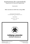
Figure 1-1 gives a block diagram for this LSI.
TDI*
TDO*
nTRST*
TMS*
TCK*
DBGEN*
DBGRQ*
DBGACK*
4 kilobytes
of RAM
ARM7TDMI
Core address bus
Interrupt
Controller
(INT)
Flexible
Timer
Analog-to-digital
Converter
(ADC)
Asynchronous
Serial Interface
(ASI)
CSI1_TXD*
CSI1_RXD*
CSI1_SCLK*
CSI0_TXD*
CSI0_RXD*
CSI0_SCLK*
Clock
Synchronous
Interface
(CSI0 and
CSI1)
Peripheral data bus 16b)
Time Base
Generator
(TBG)
ASI_TXD*
ASI_RXD*
Clock
Control
Figure 1-1 : Block Diagram
1-4
PIO0[7:0]
PIO1[7:0]
PIO2[7:0]
PIO6[7:0]
PIO7[7:0]
PIO8[7:0]
PIO3[7:0]
I/O Ports
Asterisks indicate signals that are
secondary functions of I/O ports.
Brackets indicate bit ranges.
External Memory
Controller (XMC)
Internal
Bus
Controller
Peripheral address bus
TMCLK[1:0]*
128 kilobytes
of ROM
PIO4[7:0]
TMIN/TMOUT[5:0]*
Core data bus (32b)
PIO5[7:0]
nRST
nEA
DBSEL
TEST
VDD
GND
AVDD
AGND
XA23-16*
XA15-1
nLB/XA0
XD15-8*
XD7-0
nCS0
nRD
nWRE/nWRL
nXWAIT*
nCS1*
nHB/nWRH*
nRAS1*
nWH/nCASH*
nRAS0*
nCAS/nCASL*
nWL/nWE*
nBREQ*
nBACK*
nEFIQ
nEIR[7:0]*
VREF
AI[7:0]
OSC0
OSC1
CLKOUT
FSEL
PLLEN
VCOM
Pins
Pin Layout
108
107
106
105
104
103
102
101
100
99
98
97
96
95
94
93
92
91
90
89
88
87
86
85
84
83
82
81
80
79
78
77
76
75
74
73
PIO3[4]/nEIR[4]
PIO3[3]/nEIR[3]
PIO3[2]/nEIR[2]
PIO3[1]/nEIR[1]
PIO3[0]/nEIR[0]
VDD
GND
PIO2[7]/nXWAIT
PIO2[6]/nCS1
PIO2[5]/nHB/nWRH
PIO2[4]/nRAS1
PIO2[3]/nWH/nCASH
PIO2[2]/nRAS0
PIO2[1]/nCAS/nCASL
PIO2[0]/nWL/nWE
VDD
GND
nWRE/nWRL
nRD
nCS0
PIO1[7]/XD15
PIO1[6]/XD14
PIO1[5]/XD13
PIO1[4]/XD12
PIO1[3]/XD11
PIO1[2]/XD10
PIO1[1]/XD9
PIO1[0]/XD8
VDD
GND
XD7
XD6
XD5
XD4
XD3
XD2
Figure 1-2 gives the pin layout for this LSI.
109
110
111
112
113
114
115
116
117
118
119
120
121
122
123
124
125
126
127
128
129
130
131
132
133
134
135
136
137
138
139
140
141
142
143
144
Top View
INDEX MARK
72
71
70
69
68
67
66
65
64
63
62
61
60
59
58
57
56
55
54
53
52
51
50
49
48
47
46
45
44
43
42
41
40
39
38
37
XD1
XD0
VDD
GND
nEA
nEFIQ
PIO0[7]/XA23
PIO0[6]/XA22
PIO0[5]/XA21
PIO0[4]/XA20
PIO0[3]/XA19
PIO0[2]/XA18
PIO0[1]/XA17
PIO0[0]/XA16
VDD
GND
XA15
XA14
XA13
XA12
XA11
XA10
XA9
XA8
VDD
GND
XA7
XA6
XA5
XA4
XA3
XA2
XA1
XA0/nLB
VDD
GND
1
2
3
4
5
6
7
8
9
10
11
12
13
14
15
16
17
18
19
20
21
22
23
24
25
26
27
28
29
30
31
32
33
34
35
36
PIO3[5]/nEIR[5]
PIO3[6]/nEIR[6]
PIO3[7]/nEIR[7]
GND
PIO4[0]/TMIN[0]/TMOUT[0]
PIO4[1]/TMIN[1]/TMOUT[1]
PIO4[2]/TMIN[2]/TMOUT[2]
PIO4[3]/TMIN[3]/TMOUT[3]
PIO4[4]/TMIN[4]/TMOUT[4]
PIO4[5]/TMIN[5]/TMOUT[5]
PIO4[6]/TMCLK[0]
PIO4[7]/TMCLK[1]
GND
VDD
PIO5[0]/CSI0_SCLK
PIO5[1]/CSI0_RXD
PIO5[2]/CSI0_TXD
PIO5[3]/CSI1_SCLK
PIO5[4]/CSI1_RXD
PIO5[5]/CSI1_TXD
PIO5[6]/ASI_RXD
PIO5[5]/ASI_TXD
CLKOUT
GND
OSC0
OSC1
VDD
VCOM
FSEL
PLLEN
nRST
GND
AGND
AI[7]
AI[6]
AI[5]
AI[4]
AI[3]
AI[2]
AI[1]
AI[0]
VREF
AVDD
VDD
TEST
DBSEL
PIO6[0]
PIO6[1]
PIO6[2]
PIO6[3]
PIO6[4]
PIO6[5]]
PIO6[6]]
PIO6[7]
PIO7[0]
PIO7[1]
PIO7[2]
GND
VDD
PIO7[3]
PIO7[4]
PIO7[5]
PIO7[6]/nBREQ
PIO7[7]/nBACK
PIO8[0]/DBGACK
PIO8[1]/DBGRQ
PIO8[2]/DBGEN
PIO8[3]/TCK
PIO8[4]/TMS
PIO8[5]/nTRST
PIO8[6]/TDO
PIO8[7]/TDI
1.3
1.3.1
- Directly connect all VDD pins to external power supplies and ground all VSS pins.
- AVDD, AGND, and VREF are the power supply, ground, and reference voltage pins for
the analog-to-digital converter (ADC).
Connect AVDD and VREF to VDD and AGND to VSS.
Figure 1-2 : Pin Layout
1-5
1.3.2
Pin Functions
Table 1.1 lists the functions of each pin.
Table 1.1 : Pin Functions
Type
Signal Name Pin
I/O Direction Description
Number
Address
bus
Data bus
1-6
XA23-XA16
66-59
Output
These are bits 23 - 16 of the external address bus. They
represent secondary functions for I/O port PIO0[7:0].
XA15-XA0
56-49
46-39
Output
These are bits 15 - 0 of the external address bus.
XD15-XD8
88-81
Bi-directional
These are bits 15 - 8 of the external data bus. They
represent secondary functions for I/O port PIO1[7:0].
XD7-XD0
78-71
Bi-directional
These are bits 7 - 0 of the external data bus.
Bus
nCS0
89
Output
This output is the chip select signal for bank 0.
control
signals
nCS1
100
Output
This output is the chip select signal for bank 1. It
represents a secondary function for I/O port PIO2[6].
nRD
90
Output
This output is the read signal for the SRAM banks (0 and
1).
nWRL
91
Output
This output is the Write Enable Low signal for the SRAM
banks (0 and 1).
nWRH
99
Output
This output is the Write Enable High signal for the SRAM
banks (0 and 1). It represents a secondary function for I/O
port PIO2[5].
nWRE
91
Output
This output is the Write Enable signal for the SRAM
banks (0 and 1).
nLB
39
Output
This output is the Low Byte Select signal for the SRAM
banks (0 and 1).
nHB
99
Output
This output is the High Byte Select signal for the SRAM
banks (0 and 1). It represents a secondary function for I/O
port PIO2[5].
nRAS0
96
Output
This output is the Row Address Strobe signal for bank 2.
It represents a secondary function for I/O port PIO2[2].
nRAS1
98
Output
This output is the Row Address Strobe signal for bank 3.
It represents a secondary function for I/O port PIO2[4].
nCASL
95
Output
This output is the Column Address Strobe Low signal for
the DRAM banks (2 and 3). It represents a secondary
function for I/O port PIO2[1].
nCASH
97
Output
This output is the Column Address Strobe High signal for
the DRAM banks (2 and 3). It represents a secondary
function for I/O port PIO2[3].
nWE
94
Output
This output is the Write Enable signal for the DRAM
banks (2 and 3). It represents a secondary function for
I/O port PIO2[0].
Table 1.1 : Pin Functions
Type
Signal Name Pin
I/O Direction Description
Number
Bus
control
signals
Interrupts
Timers
Serial
ports
nCAS
95
Output
This output is the Column Address Strobe signal for the
DRAM banks (2 and 3). It represents a secondary function
for I/O port PIO2[1].
nWH
97
Output
This output is the Write Enable High signal for the
DRAM banks (2 and 3). It represents a secondary function
for I/O port PIO2[3].
nWL
94
Output
This output is the Write Enable Low signal for the DRAM
banks (2 and 3). It represents a secondary function for I/O
port PIO2[0].
nXWAIT
101
Input
This input pin controls insertion of wait cycles. It
represents a secondary function for I/O port PIO2[7].
nBREQ
27
Input
This input is a bus request signal from an external device.
It represents a secondary function for I/O port PIO7[6].
nBACK
28
Output
This output is an acknowledgment signal to a bus request
signal from an external device. It represents a secondary
function for I/O port PIO7[7].
nEFIQ
67
Input
This input is an external fast interrupt request (FIQ).
When accepted, the request is processed as an FIQ
exception.
nEIR[7:0]
111-104
Input
These inputs are external interrupt requests. They
represent secondary functions for I/O port PIO3[7:0].
TMIN[5:0]
118-113
Input
These pins function as capture trigger input pins for
Flexible Timer (FTM) channels 5 - 0 in capture (CAP)
mode. They represent secondary functions for I/O port
PIO4[5:0].
TMOUT[5:0]
118-113
Output
These pins function as output pins for Flexible
Timer(FTM) channels 5 - 0 in compare out (CMO) or
pulse width modulation (PWM) mode. They represent
secondary functions for I/O port PIO4[5:0].
TMCLK[1:0]
120,119
Input
These pins function as Flexible Timer (FTM) channel 1
and 0 clock input pins. They represent secondary
functions for I/O port PIO4[7:6].
ASI_TXD
130
Output
This output is the transmit data for the Asynchronous
Serial Interface (ASI). It represents a secondary function
for I/O port PIO5[7].
ASI_RXD
129
Input
This input is the receive data for the Asynchronous Serial
Interface (ASI). It represents a secondary function for I/O
port PIO5[6].
CSI0_TXD
125
Output
This output is the transmit data for the Clock Synchronous
Interface 0(CSI0). It represents a secondary function for
I/O port PIO5[2].
CSI0_RXD
124
Input
This input is the receive data for the Clock Synchronous
Interface 0 (CSI0). It represents a secondary function for
I/O port PIO5[1].
1-7
Table 1.1 : Pin Functions
Type
Signal Name Pin
I/O Direction Description
Number
Serial
ports
CSI0_SCLK
123
Bi-directional
This pin accepts/provides the clock signal for the Clock
Synchronous Interface 0 (CSI0). It represents a secondary
function for I/O port PIO5[0].
CSI1_TXD
128
Output
This output is the transmit data for the Clock Synchronous
Interface 1 (CSI1). It represents a secondary function for
I/O port PIO5[5].
CSI1_RXD
127
Input
This input is the receive data for the Clock Synchronous
Interface 1 (CSI1). It represents a secondary function for
I/O port PIO5[4].
CSI1_SCLK
126
Bi-directional
This pin accepts/provides the clock signal for the Clock
Synchronous Interface 1 (CSI1). It represents a secondary
function for I/O port PIO5[3].
Analog-to- VREF
digital
6
Input
This input is the reference voltage for the analog-to-digital
converter. Connect it to V DD .
converter
142-144
1-5
Input
These are analog signal input pins for analog-to-digital
converter channels 7 - 0.
36
Input
This input is the serial data input for the debugging scan
circuit. It represents the secondary function for I/Oport
PIO8[7].
TDO
35
Output
This output is the serial data output for the debugging
scan circuit. It represents the secondary function for I/O
port PIO8[6].
nTRST
34
Input
"L" level input to this pin resets the debugging scan
circuit. It represents the secondary function for I/O port
PIO8[5].
TMS
33
Input
This input selects the mode for the debugging scan circuit.
It represents the secondary function for I/O port PIO8[4].
TCK
32
Input
This input is the serial clock input for the debugging scan
circuit. It represents the secondary function for I/O port
PIO8[3].
DBGEN
31
Input
"High" level input to this pin enables the CPU's
debugging function. It represents the secondary function
for I/O port PIO8[2].
DBGRQ
30
Input
This input is a debugging request signal from an external
device. It represents the secondary function for I/O port
PIO8[1].
DBGACK
29
Output
This output is an acknowledgment signal to a debugging
request signal from an external device. It represents the
secondary function for I/O port PIO8[0].
AI[7:0]
Debugging TDI
interface
1-8
Table 1.1 : Pin Functions
Type
Signal Name Pin
I/O Direction Description
Number
I/O ports
Clock
control
System
control
PIO8[7:0]
36-29
Bi-directional
These form an 8-bit I/O port. I/O directions are specified
at the bit level.
PIO7[7:0]
28-24
21-19
Bi-directional
These form an 8-bit I/O port. I/O directions are specified
at the bit level.
PIO6[7:0]
18-11
Bi-directional
These form an 8-bit I/O port. I/O directions are specified
at the bit level.
PIO5[7:0]
130-123
Bi-directional
These form an 8-bit I/O port. I/O directions are specified
at the bit level.
PIO4[7:0]
120-113
Bi-directional
These form an 8-bit I/O port. I/O directions are specified
at the bit level.
PIO3[7:0]
111-104
Bi-directional
These form an 8-bit I/O port. I/O directions are specified
at the bit level.
PIO2[7:0]
101-94
Bi-directional
These form an 8-bit I/O port. I/O directions are specified
at the bit level.
PIO1[7:0]
88-81
Bi-directional
These form an 8-bit I/O port. I/O directions are specified
at the bit level.
PIO0[7:0]
66-59
Bi-directional
These form an 8-bit I/O port. I/O directions are specified
at the bit level.
OSC0
133
Input
This pin is for connecting a crystal oscillator. If an
external clock is used, supply it to this pin.
OSC1
134
Output
This pin is for connecting a crystal oscillator. If an
external clock is used, leave this pin open.
CLKOUT
131
Output
This output is the internal system clock (SYSCLK) signal.
FSEL
137
Input
Connect this pin to VDD or ground to indicate the
frequency range for the basic clock.
PLLEN
138
Input
Connecting this pin to VDD enables the built-in
phase-locked loop. If the PLL is not used because an
external clock with a guaranteed duty is available, connect
this pin to ground.
VCOM
136
Input
This input controls the oscillation frequency of the PLL's
voltage-controlled oscillator. Connect it to ground.
nRST
139
Input
"L" level input to this pin produces an external system
reset for this LSI. "H" level input then causes execution to
resume from address 0x000000.
DBSEL
10
Input
During a system reset of this LSI, this input specifies the
width of the external data bus for bank 0. Connect this pin
to VDD for a data bus width of 16 bits and to ground for 8
bits.
nEA
68
Input
During a system reset of this LSI, this input controls the
use of the internal ROM. Connect this pin to VDD to
enable the ROM and to ground to disable it..
1-9
Table 1.1 : Pin Functions
Type
Signal Name Pin
I/O Direction Description
Number
1.3.3
System
control
TEST
9
Input
During a system reset of this LSI, this input controls the
initial pin functions for the I/O port 8 pins (PIO8[7:0]).
Connect this pin to VDD to initialize the port for its
secondary function, the debugging interface, and to
ground for I/O.
Power
supply
VDD
8,23,38,
48,58,70,
80,93,
103,122,
135
Input
These pins are this LSI's power supply pins. Connect
them all to VDD .
GND
22,37,47,
57,69,79,
92,102,
112,121,
132,140
Input
These pins are this LSI's ground pins. Connect them all
to ground.
AVDD
7
Input
This pin is the analog-to-digital converter's power
supply. Connect it to VDD .
AGND
141
Input
This pin is the analog-to-digital converter’s ground pin.
Connect it to ground.
Treatment of Unused Pins
Table 1.2 lists the connections for unused pins.
Table 1.2 : Treatment of Unused Pins
Pin Name(s)
Treatment
1-10
PIO8-PIO0
Input configuration: Connect to VDD or ground through resistors.
Output configuration: Leave open.
nEFIQ
Connect to VDD .
VREF
Connect to VDD .
AI [7:0]
Connect to VDD or ground.
TEST
Connect to VDD or ground.
nTRST
Connect to ground through resistors
TDI,TMS,TCK
Connect to VDD through resistors
TDO
Leave open
1.3.4
Configurations of Pins and I/O ports
(1) Input Pins (nRST, nEA, DBSEL, TEST, nEFIQ, FSEL, PLLEN, VCOM)
VDD
Input pins
(high impedance)
GND
(2) Output Pin (CLKOUT)
VDD
Output pin
(CMOS output)
GND
(3) Tri-state output pins (XA23 - XA1, nLB/XA0, nCS0, nRD, nWRE/nWRL)
Output enable
signal
Output pins
(CMOS output when enabled)
(4) Bi-directional pins (XD7 - XD0)
Output enable
signal
Bi-directional pins
(CMOS output when enabled)
Read signal
1-11
(5) I/O port A (I/O ports without secondary functions)
PIO6[7:0], PIO7[5:0]
PMm [n]
Peripheral bus
POm [n]
PIOm [n]
Read PIm [n]
(6) I/O port B (I/O ports with secondary functions of input)
PIO2[7], PIO3[7:0] , PIO4[7:6] , PIO5[6] , PIO5[4], PIO5[1] , PIO7[6] , PIO8[7] , PIO8[5:1]
PMm [n]
POm [n]
Secondary function
input signal
PFSm [n]
Peripheral bus
PIOm [n]
Read PIm [n]
1-12
(7) I/O port C (I/O ports with secondary functions of output)
PIO5[7], PIO5[5], PIO5[2], PIO7[7], PIO8[6], PIO8[0]
PMm [n]
POm [n]
Secondary function
output signal
PFSm [n]
Peripheral bus
PIOm [n]
Read PIm [n]
1-13
(8) I/O port D (I/O ports with secondary functions of tri-state output)
PIO0[7:0], PIO2[6:0]
PMm [n]
Secondary function output
enable signal
POm [n]
Secondary function
output signal
PFSm [n]
Peripheral bus
PIOm [n]
Read PIm [n]
1-14
(9) I/O port E (I/O ports with secondary functions of input and output)
PIO1[7:0], PIO4[5:0], PIO5[3], PIO5[0]
PMm [n]
Secondary function output
enable signal
POm [n]
Secondary function
output signal
Secondary function
input signal
PFSm [n]
Peripheral bus
PIOm [n]
Read PIm [n]
1-15
1-16
2
CPU
This LSI uses as its CPU the ARM7TDMI core developed by ARM Limited. This CPU offers the
programmer a choice of two states: ARM state, executing 32-bit ARM instructions, and THUMB
state, executing 16-bit THUMB instructions, a subset of ARM instructions.
2.1
CPU Operating States
2-2
2.2
Switching State
2-2
2.3
Memory Formats
2-2
2.4
Instruction Length
2-3
2.5
Data Types
2-3
2.6
Operating Modes
2-3
2.7
Registers
2-3
2.8
2.9
2.10
2.7.1
The ARM state register set
2-4
2.7.2
The THUMB state register set
2-6
2.7.3
The relationship between ARM and THUMB state registers
2-7
2.7.4
Accessing Hi registers in THUMB state
2-7
The Program Status Registers
2-8
2.8.1
The condition code flags
2-8
2.8.2
The control bits
2-8
Exceptions
2-9
2.9.1
Action on entering an exception
2-10
2.9.2
Action on leaving an exception
2-10
2.9.3
Exception entry/exit summary
2-10
2.9.4
FIQ
2-11
2.9.5
IRQ
2-11
2.9.6
Software interrupt
2-12
2.9.7
Undefined instruction
2-12
2.9.8
Exception vectors
2-12
2.9.9
Exception priorities
Reset
2-13
2-13
2-1
2.1
CPU Operating States
From the programmer's point of view, the CPU can be in one of two states:
ARM state
which executes 32-bit, word-aligned ARM instructions.
THUMB state which operates with 16-bit, halfword-aligned THUMB instructions. In this state,
the PC uses bit 1 to select between alternate halfwords.
Note :
2.2
Transition between these two states does not affect the CPU mode or the contents of
the registers.
Switching State
Entering THUMB state
Entry into THUMB state can be achieved by executing a BX instruction with the state bit (bit 0)
set in the operand register.
Transition to THUMB state will also occur automatically on return from an exception(IRQ, FIQ,
UNDEF, SWI etc.), if the exception was entered with the processor in THUMB state.
Entering ARM state
Entry into ARM state happens:
1 On execution of the BX instruction with the state bit clear in the operand register.
2 On the processor taking an exception (IRQ, FIQ, RESET, UNDEF, SWI etc.).
In this case, the PC is placed in the exception mode's link register, and execution
commences at the exception's vector address.
2.3
Memory Formats
The CPU views memory as a linear collection of bytes numbered upwards from zero.
Bytes 0 to 3 hold the first stored word, bytes 4 to 7 the second and so on. The CPU can treat
words in memory as being stored in Little Endian format.
Note :
Higher Address
The core architecture supports both big- and little- endian formats, but this LSI uses
only the latter.
31
11
7
3
24
23
10
6
2
16
15
9
5
1
8
7
8
4
0
0
Word Address
8
4
0
Lower Address
-Least significant byte is at lowest address
-Word is addressed by byte address of least significant byte
Figure 2.1 : Little endian addresses of bytes within words
2-2
2.4
Instruction Length
Instructions are either 32 bits long (in ARM state) or 16 bit long (in THUMB state).
2.5
Data Types
The CPU supports byte (8-bit), halfword (16-bit) and word (32-bit) data types.
Words must be aligned to four-byte boundaries and half words to two-byte boundaries.
2.6
Operating Modes
The CPU supports six modes of operation:
User (usr):
The normal ARM program execution state
FIQ(fiq):
Designed to support a data transfer or channel process
IRQ(irq):
Used for general-purpose interrupt handling
Supervisor (sys):
Protected mode for the operating system.
System (sys):
A privileged user mode for the operating system
Undefined(und):
Entered when an undefined instruction is executed
Note :
The core architecture offers an additional mode, Abort mode, but this LSI does not
use it.
Mode changes may be made under software control, or may be brought about by interrupts or
exception processing. Most application programs will execute in User mode.
The non-user modes -known as privileged modes- are entered in order to service interrupts or
exceptions, or to access protected resources.
2.7
Registers
The CPU has a total of 34 registers -29 general-purpose 32-bit registers and five status
registers- but these cannot all be seen at once. The CPU state and operating mode dictate
which registers are available to the programmer.
Note :
The core architecture offers an additional two general-purpose registers and one
status register for use with the Abort mode, which this LSI does not support.
2-3
2.7.1
The ARM state register set
In ARM state, 16 general registers and one or two status registers are visible at any one time. In
privileged (non-User) modes, mode-specific banked registers are switched in.
Figure 2.2 : Register organization in ARM state shows which registers are available in each
mode: the banked registers are marked with a shaded triangle.
The ARM state register set contains 16 directly accessible registers: R0 to R15. All of these
except R15 are general-purpose, and may be used to hold either data or address values.
In addition to these, there is a seventeenth register used to store status information.
Register 14
is used as the subroutine link register. This receives a copy of R15 when a
Branch and Link (BL) instruction is executed. At all other times it may be
treated as a general-purpose register. The corresponding banked registers
R14_svc, R14_irg, R14_fiq, and R14_und are similarly used to hold the
return values of R15 when interrupts and exceptions arise, or when Branch
and Link instructions are executed within interrupt or exception routines.
Register 15
holds the Program Counter (PC). In ARM state, bits [1:0] of R15 are zero and
bits [31:2] contain the PC. In THUMB state, bit [0] is zero and bits [31:1]
contain the PC.
Register 16
is the CPSR (Current Program Status Register). This contains condition code
flags and the current mode bits.
FIQ mode has seven banked registers mapped to R8-14 (R8_fiq-R14_fiq). In ARM state, many
FIQ handlers do not need to save any registers. User, IRQ, Supervisor and Undefined each have
two banked registers mapped to R13 and R14, allowing each of these modes to have a private
stack pointer and link registers.
2-4
ARM State General Registers and Program Counter
System & User
R0
R1
R2
R3
R4
R5
R6
R7
R8
R9
R10
R11
R12
R13
R14
R15(PC)
FIQ
R0
R1
R2
R3
R4
R5
R6
R7
R8_fiq
R9_fiq
R10_fiq
R11_fiq
R12_fiq
R13_fiq
R14_fiq
R15(PC)
Supervisor
R0
R1
R2
R3
R4
R5
R6
R7
R8
R9
R10
R11
R12
R13_svc
R14_svc
R15(PC)
IRQ
R0
R1
R2
R3
R4
R5
R6
R7
R8
R9
R10
R11
R12
R13_irq
R14_irq
R15(PC)
Undefined
R0
R1
R2
R3
R4
R5
R6
R7
R8
R9
R10
R11
R12
R13_und
R14_und
R15(PC)
ARM State Program Status Registers
CPSR
CPSR
SPSR_fiq
CPSR
SPSR_svc
CPSR
SPSR_irq
CPSR
SPSR_und
=banked register
Figure 2.2 : Register organization in ARM state
2-5
2.7.2
The THUMB state register set
The THUMB state register set is a subset of the ARM state set. The programmer has direct
access to eight general registers, R0-R7, as well as the Program Counter (PC), a stack pointer
register (SP), a link register (LR), and the CPSR. There are banked Stack Pointers, Link
Registers and Saved Program Status Registers (SPSRs) for each privileged mode. This is shown
in Figure 2.3: Register organization in THUMB state.
THUMB State General Registers and Program Counter
System & User
R0
R1
R2
R3
R4
R5
R6
R7
SP
LR
PC
FIQ
R0
R1
R2
R3
R4
R5
R6
R7
SP _fiq
LR_fiq
PC
Supervisor
R0
R1
R2
R3
R4
R5
R6
R7
SP_svc
LR_svc
PC
IRQ
R0
R1
R2
R3
R4
R5
R6
R7
SP_irq
LR_irq
PC
Undefined
R0
R1
R2
R3
R4
R5
R6
R7
SP_und
LR_und
PC
THUMB State Program Status Registers
CPSR
CPSR
SPSR_fiq
CPSR
SPSR_svc
CPSR
SPSR_irq
CPSR
SPSR_und
=banked register
Figure 2.3 : Register organization in THUMB state
2-6
2.7.3
The relationship between ARM and THUMB state registers
The THUMB state registers relate to the ARM state registers in the following way:
• THUMB state R0-R7 and ARM state R0-R7 are identical
• THUMB state CPSR and SPSRs and ARM state CPSR and SPSRs are identical
• THUMB state SP maps onto ARM state R13
• THUMB state LR maps onto ARM state R14
• The THUMB state Program Counter maps onto the ARM state Program Counter (R15)
ARM State
R0
R1
R2
R3
R4
R5
R6
R7
R0
R1
R2
R3
R4
R5
R6
R7
R8
R9
R10
R11
R12
Stack Pointer (R13)
Link Register (R14)
Program Counter (R15)
CPSR
SPSR
Stack Pointer (SP)
Link Register (LR)
Program Counter (PC)
CPSR
SPSR
Hi Registers
THUMB State
Lo Registers
This relationship is shown in Figure 2.4: Mapping of THUMB state registers onto ARM state
registers.
Figure 2.4 : Mapping of THUMB state registers onto ARM state registers
2.7.4
Accessing Hi registers in THUMB state
In THUMB state, registers R8-R15 (the Hi registers) are not part of the standard register set.
However, the assembly language programmer has limited access to them, and can use them for
fast temporary storage.
A value may be transferred from a register in the range R0-R7 (a Lo register) to a Hi register,
and from a Hi register to a Lo register, using special variants of the MOV instruction. Hi
register values can also be compared against or added to Lo register values with the CMP and
ADD instructions.
2-7
2.8
The Program Status Registers
The CPU contains a Current Program Status Register (CPSR), plus four Saved Program
Status Registers (SPSRs) for use by exception handlers. These registers
• hold information about the most recently performed ALU operation
• control the enabling and disabling of interrupts
• set the processor operating mode
The arrangement of bits is shown in Figure 2.5: Program status register format.
condition code flags
31
N
30
Z
29
C
28
V
(reserved)
27
-
26
-
25
-
24
-
23
-
control bits
-
8
-
7
I
6
F
5
T
4
3
2
1
0
M4 M3 M2 M1 M0
Overflow
Carry/Borrow/Extend
Zero
Negative/Less Than
Mode bits
State bit
FIQ disable
IRQ disable
Figure 2.5 : Program status register format
2.8.1
The condition code flags
The N, Z, C and V bits are the condition code flags. These may be changed as a result of
arithmetic and logical operations, and may be tested to determine whether an instruction should
be executed.
In ARM state, all instructions may be executed conditionally.
In THUMB state, only the Branch instruction is capable of conditional execution.
2.8.2
The control bits
The bottom 8 bits of a PSR (incorporating I, F, T and M [4:0]) are known collectively as the
control bits. These will change when an exception arises. If the CPU is executing in a privileged
mode, they can also be manipulated by software.
The T bit
This reflects the operating state. When this bit is set, the CPU is
executing in THUMB state, otherwise it is executing in ARM state.
Note that the software must never change the state of the TBIT in the
CPSR. If this happens, the CPU will enter an unpredictable state.
Interrupt disable bits
The I and F bits are interrupt disable bits. When set, these disable
the IRQ and FIQ interrupts respectively.
2-8
The mode bits
The M4, M3, M2, M1 and M0 bits (M[4:0]) are the mode bits.
These determine the CPU's operating mode, as shown in Table 2.1
PSR mode bit values. Not all combinations of the mode bits define a
valid CPU mode. Only those explicitly described shall be used. The
user should be aware that if any illegal value is programmed into the
mode bits, M [4:0], then the CPU will enter an unrecoverable state.
If this occurs, reset should be applied.
Reserved bits
The remaining bits in the PSRs are reserved. When changing a PSR's
flag or control bits, you must ensure that these unused bits are not
altered. Also, your program should not rely on them containing
specific values, since in future CPUs they may read as one or zero.
Table 2.1 : PSR mode bit values
M[4:0]
Mode
Visible THUMB state registers
R7..R0,
User
10000
LR, SP
PC, CPSR
2.9
Visible ARM state registers
R14..R0,
PC, CPSR
10001
FIQ
R7..R0,
LR_fiq, SP_fiq
PC, CPSR, SPSR_fiq
R7..R0,
R14_fiq..R8_fiq,
PC, CPSR, SPSR_fiq
10010
IRQ
R7..R0,
LR_irq, SP_irq
PC, CPSR, SPSR_irq
R12..R0,
R14_irq..R13_irq,
PC, CPSR, SPSR_irq
10011
Supervisor
R7..R0,
LR_svc, SP_svc,
PC, CPSR, SPSR_svc
R12..R0,
R14_svc..R13_svc,
PC, CPSR, SPSR_svc
11011
Undefined
R7..R0
LR_und, SP_und,
PC, CPSR, SPSR_und
R12..R0,
R14_und..R13_und,
PC, CPSR
11111
System
R7..R0,
LR, SP
PC, CPSR
R14..R0,
PC, CPSR
Exceptions
Exceptions arise whenever the normal flow of a program has to be halted temporarily, for
example to service an interrupt from a peripheral. Before an exception can be handled, the
current CPU state must be preserved so that the original program can resume when the handler
routine has finished.
It is possible for several exceptions to arise at the same time. If this happens, they are dealt with
in a fixed order -see 2.9.9 Exception priorities.
2-9
2.9.1
Action on entering an exception
When handling an exception, the CPU:
1
Preserves the address of the next instruction in the appropriate Link Register. If the
exception has been entered from ARM state, then the address of the next instruction is
copied into the Link Register (that is, current PC + 4 or PC + 8 depending on the
exception. See Table 2.2 Exception entry/exit for details). If the exception has been
entered from THUMB state, then the value written into the exception has been entered
from THUMB state, then the value written into the Link Register is the current PC offset
by a value such that the program resumes from the correct place on return from the
exception. This means that the exception handler need not determine which state the
exception was entered from. For example, in the case of SWI, MOVS PC, R14_svc will
always return to the next instruction regardless of whether the SWI was executed in
ARM or THUMB state.
2
Copies the CPSR into the appropriate SPSR
3
Forces the CPSR mode bits to a value which depends on the exception
4
Forces the PC to fetch the next instruction from the relevant exception vector
It may also set the interrupt disable flags to prevent otherwise unmanageable nestings of
exceptions.
If the CPU is in THUMB state when an exception occurs, it will automatically switch into ARM
state when the PC is loaded with the exception vector address.
2.9.2
Action on leaving an exception
On completion, the exception handler:
1
Moves the Link Resister, minus an offset where appropriate, to the PC.(The offset will
vary depending on the type of exception.)
2
Copies the SPSR back to the CPSR
3
Clears the interrupt disable flags, if they were set on entry
Note :
2.9.3
An explicit switch back to THUMB state is never needed, since restoring the
CPSR from the SPSR automatically sets the T bit to the value it held immediately
prior to the exception.
Exception entry/exit summary
Table 2.2 : Exception entry/exit summarizes the PC value preserved in the relevant R14 on
exception entry, and the recommended instruction for exiting the exception handler.
2-10
Table 2.2 : Exception entry/exit
Return Instruction
Previous State
THUMB
ARM
R14_x
R14_x
Notes
BL
MOV PC, R14
PC + 4
PC + 2
1
SWI
MOVS PC, R14_svc
PC + 4
PC + 2
1
UDEF
MOVS PC, R14_und
PC + 4
PC + 2
1
FIQ
SUBS PC, R14_fiq, #4
PC + 4
PC + 4
2
IRQ
SUBS PC, R14_irq, #4
PC + 4
PC + 4
2
RESET
NA
-
-
3
Note :
1
Where PC is the address of the BL/SWI/Undefined Instruction.
2
Where PC is the address of the instruction which did not get executed since the FIQ or
IRQ took priority.
3
2.9.4
The value saved in R14_svc upon reset is unpredictable.
FIQ
The FIQ (Fast Interrupt Request) exception is designed to support a data transfer or channel
process, and in ARM state has sufficient private registers to remove the need for register saving
(thus minimizing the overhead of context switching).
Irrespective of whether the exception was entered from ARM or Thumb state, a FIQ handler
should leave the interrupt by executing
SUBS PC, R14_fig, #4
FIQ may be disabled by setting the CPSR's F flag (but note that this is not possible from User
mode).
2.9.5
IRQ
The IRQ (Interrupt Request) exception is a normal interrupt. IRQ has a lower priority than FIQ
and is masked out when a FIQ sequence is entered. It may be disabled at any time by setting the
I bit in the CPSR, though this can only be done from a privileged (non-User) mode.
Irrespective of whether the exception was entered from ARM or Thumb state, an IRQ handler
should return from the interrupt by executing.
SUBS PC, R14_irq, #4
2-11
2.9.6
Software interrupt
The software interrupt instruction (SWI) is used for entering Supervisor mode, usually to
request a particular supervisor function. A SWI handler should return by executing the
following irrespective of the state (ARM or Thumb):
MOV PC, R14_svc
This restores the PC and CPSR, and returns to the instruction following the SWI.
2.9.7
Undefined instruction
When the CPU comes across an instruction which it cannot handle, it takes the undefined
instruction trap. This mechanism may be used to extend either the THUMB or ARM instruction
set by software emulation.
After emulating the failed instruction, the trap handler should execute the following irrespective
of the state (ARM or Thumb):
MOVS PC, R14_und
This restores the CPSR and returns to the instruction following the undefined instruction.
2.9.8
Exception vectors
The following table shows the exception vector addresses.
Table 2.3 : Exception vectors
Address
0x00000000
Reset
Exception
Mode on entry
Supervisor
0x00000004
Undefined instruction
Undefined
0x00000008
Software interrupt
Supervisor
0x0000000C
Reserved
Reserved
0x00000010
Reserved
Reserved
0x00000014
Reserved
Reserved
0x00000018
IRQ
IRQ
0x0000001C
FIQ
FIQ
2-12
2.9.9
Exception priorities
When multiple exceptions arise at the same time, a fixed priority system determines the order in
which they are handled:
Highest priority:
1
2
3
Reset
FIQ
IRQ
Lowest priority:
4
Undefined Instruction, software interrupt.
Not all exceptions can occur at once:
Undefined Instruction and Software Interrupt are mutually exclusive, since they each correspond
to particular (non-overlapping) decodings of the current instruction.
2.10
Reset
After a system reset, the CPU:
1
Overwrites R14_svc and SPSR_svc by copying the current values of the PC
and CPSR into them. The value of the saved PC and SPSR is not defined.
2
Forces M [4:0] to 10011(Supervisor mode), sets the I and F bits in the CPSR.
3
Forces the PC to fetch the next instruction from address 0x00.
4
Execution resumes in ARM state.
2-13
2-14
3
CPU Control Functions
3.1
Overview
3.2
3.3
3-2
3.1.1
Pins
3-2
3.1.2
Control Registers
3-3
Control Registers
3-3
3.2.1
Standby Control Register (SBYCON)
3-3
3.2.2
Clock Control Register (CKCON)
3-4
3.2.3
Reset Status Register (RSTST)
3-5
System Resets
3-6
3.3.1
External Reset Signal (nRST)
3-6
3.3.2
Watchdog Timer (WDT) Counter Overflow
3-6
3.4
Clock Signals
3-7
3.5
Standby Mode
3-8
3-1
3.1
Overview
CPU control functions for this LSI include the following.
3.1.1
•
Reset control
This function controls the system reset function for initializing the CPU and on-chip
peripherals.
•
Clock control
This function controls the oscillator circuit based on a crystal oscillator and a built-in
phase-locked loop which together generate and control the system clock (SYSCLK)
signal. It offers a choice of divider ratio (1/1, 1/2, and 1/4) for adjusting operating clock
frequency to match the load of processing.
•
Standby mode control
This function controls the transitions to and from HALT mode.
Pins
Table 3.1 lists the pins connected to the CPU control unit.
Table 3.1 : CPU Control Unit Pins
Pin Name
Symbol
Direction
Reset input
Description
nRST
input
"L" level input to this pin produces an external system
reset for this LSI. "H" level input then causes execution to
resume from address 0x000000.
Crystal oscillator input pin OSC0
input
This pin is for connecting a crystal oscillator. If an
external clock is used, supply it to this pin.
Crystal oscillator output
pin
OSC1
output
This pin is for connecting a crystal oscillator. If an
external clock is used, leave this pin open
System clock (SYSCLK)
output
CLKOUT
output
This output is the internal system clock (SYSCLK) signal.
PLL enable input
PLLEN
input
Connecting this pin to V DD enables the built-in
phase-locked loop. If the PLL is not used because an
external clock with a guaranteed duty is available, connect
this pin to ground.
PLL frequency divider
selection input
FSEL
input
Connect this pin to V DD or ground to indicate the
frequency range for the basic clock.
VCO frequency selection
input
VCOM
input
This input controls the oscillation frequency of the PLL's
voltage-controlled oscillator.
Connect it to ground.
3-2
3.1.2
Control Registers
Table 3.2 lists the control registers for the CPU control unit.
Reads from these control registers takes exactly one clock cycle; writes, at least two. Modifying
the standby control (SBYCON) or clock control (CKCON) register requires two operations:
writing 0x0000003C and then writing the new value. Without the first, the second is ignored.
Table 3.2 : CPU Control Unit Control Registers
Address
Name
Symbol
3.2
3.2.1
R/W Size
(bits)
Initial value
0x040_0000
Standby Control Register
SBYCON
W
32
0x00000000
0x040_0004
Clock Control Register
CKCON
R/W
32
0x00000000
0x040_000C
Reset Status Register
RSTST
R
32
0x00000000
Control Registers
Standby Control Register (SBYCON)
The Standby Control Register (SBYCON) is a 32-bit write-only register containing a control bit
for switching to HALT mode. After a system reset, it contains 0x00000000.
31
30
0
0
-- -
3
2
1
0
0
0
0
HLT
A "0" indicates a reserved bit. Always write "0" to it.
Writing "1" produces unreliable operation.
Figure 3.1 : Standby Control Register (SBYCON)
Bit Descriptions
HLT
This is HALT mode control bit. Writing "1" to this bit switches this LSI to HALT mode,
suspending operation of the CPU, but leaving the peripheral circuits operational. The LSI
automatically resets this bit to "0" when it wakes from HALT mode.
3-3
The LSI ignores the above transition requests when
(1) a preceding interrupt request has set a bit in the Interrupt Request Registers 0 to 3 (IRRn,
n=0 - 3) to "1" and the corresponding interrupt level for the interrupt in the Interrupt Level
Control Registers 0 to 15 (ILCONn, n=0 - 15) is nonzero - that is, 1 to 7.
(2) a preceding external fast interrupt request (FIQ) has set the EFIQR bit in the External FIQ
Control Register (EFIQCON) to "1" and the EFIQM bit in the same register does not mask
such requests - that is, is "0".
(3) I/O port 8 is configured for its secondary function, and DBGRQ (PIO8[1]) is asserted.
In the first case, either clear the bit in the Interrupt Request Register (IRRn) or set the interrupt
level to zero and then write to SBYCON.
In the second case, either clear the EFIQR bit to "0" or mask external fast interrupt requests by
setting the EFIQM bit to "1" and then write to SBYCON.
In the third case, wait for the external device to negate DBGRQ, terminating debugging, and
then write to SBYCON.
3.2.2
Clock Control Register (CKCON)
The Clock Control Register (CKCON) is a 32-bit read/write register controlling the frequency
divider ratio for the system clock (SYSCLK) signal for the CPU and on-chip peripherals. After
a system reset, it contains 0x00000000.
31
30
0
0
-- -
3
2
0
0
1
0
CKM
00
01
0X
Frequency 1/4 that of PLL output
Frequency 1/2 that of PLL output
Frequency 1/1 that of PLL output
X: don't care
A "0" indicates a reserved bit. Always write "0" to it.
Writing "1" produces unreliable operation.
Figure 3.2 : Clock Control Register (CKCON)
Bit Descriptions
CKM
This field specifies a frequency divider ratio. The choices are 1, 1/2, and 1/4. The LSI applies
this ratio to the PLL output to derive the system clock (SYSCLK) signal for the CPU and
on-chip peripherals.
3-4
3.2.3
Reset Status Register (RSTST)
The Reset Status Register (RSTST) is a 32-bit read-only register indicating the trigger for the
most recent system reset. The external reset signal (nRST) sets this register to 0x00000000; the
Watchdog Timer (WDT) counter overflow signal (WDTOV), to 0x00000001.
31
30
0
0
-- -
3
2
1
0
0
0
0
WDTRST
0
1
External reset
Watchdog Timer (WDT) counter
overflow
A "0" indicates a reserved bit. Always write "0" to it.
Writing "1" produces unreliable operation.
Figure 3.4 : Reset Status Register (RSTST)
Bit Descriptions
WDTRST
This flag indicates the trigger for the most recent system reset. A "0" indicates the external reset
signal (nRST); a "1," the Watchdog Timer (WDT) counter overflow signal(WDTOV).
3-5
3.3
System Resets
This LSI has two sources for system resets:
• External reset signal (nRST)
• Watchdog Timer (WDT) counter overflow signal (WDTOV)
3.3.1
External Reset Signal (nRST)
Asserting the external reset signal (nRST) asserts the LSI's internal reset signal for the
assert time plus nine clock cycles, resetting the CPU and on-chip peripherals and initializing
the following registers.
• The LSI initializes the Standby Control Register (SBYCON) to 0x00000000 and
wakes from HALT mode.
• The LSI initializes the Reset Status Register (RSTST) to 0x00000000.
It is up to the signal source to assert the signal long enough to cover both the crystal oscillator
circuit stabilization period and the PLL lock time.
3.3.2
Watchdog Timer (WDT) Counter Overflow
Watchdog Timer (WDT) counter overflow signal (WDTOV) asserts the internal reset signal for
nine clock cycles, resetting the CPU and all on-chip peripherals except the I/O ports, and the
Clock Control Register (CKCON) in the CPU control unit. By not initializing the I/O ports and
CKCON, the LSI maintains the I/O port direction settings (input/output), I/O port pin function
settings (primary/secondary), I/O port output levels and CKCON setting (clock frequency
divider ratio) in effect before the reset.
3-6
•
The LSI resets the HLT bit in the Standby Control Register (SBYCON) to "0" to wake
from HALT mode.
•
The LSI initializes the Reset Status Register (RSTST) to 0x00000001.
3.4
Clock Signals
The basic clock signal is either the oscillation clock from the oscillator circuit or an external
clock signal.
Table 3.3 : Clock Sources
Clock source
OSC0
External source
Clock input
Crystal oscillator
Connect crystal oscillator
OSC1
Open
If the PLLEN input enables PLL operation, specify the frequency multiplier from Table 3.4
matching the frequency range for the basic clock signal from the oscillator circuit or an external
clock signal.
Table 3.4 : FSEL Pin Settings
Basic clock frequency FSEL Input
from the oscillator
circuit or an external
clock signal
Multiplier
PLL Output Clock
Frequency
16-25MHz
4-6.25MHz
"H" level
(Connect to V DD .)
x4
8-12.5MHz
"L" level
(Connect to ground.)
x2
The frequency for the system clock (SYSCLK) signal, the clock for CPU and on-chip
peripherals, is determined by the CKM field in the Clock Control Register (CKCON). The
frequency of SYSCLK is limited to the range of 4 to 25MHz.
The LSI permits adjusting this setting - and thus the operating clock frequency - to match the
processing load.
Table 3.5 : System Clock (SYSCLK) Frequencies
CKM
System clock (SYSCLK) frequency
00
Frequency 1/4 that of PLL output
01
Frequency 1/2 that of PLL output
1X
Frequency 1/1 that of PLL output
X : don’t care
3-7
3.5
Standby Mode
Writing "1" to the HLT bit in the Standby Control Register (SBYCON) switches this LSI to
HALT mode. This mode suspends operation of the CPU but the peripheral circuits remain
operational.
The LSI remains in HALT mode until one of the following conditions is met:
• There is an external fast interrupt request (FIQ) and such requests are not masked.
• There is an external interrupt request and such requests are not masked.
• There is an internal interrupt request and such requests are not masked.
• An external reset signal (nRST) or Watchdog Timer (WDT) counter overflow signal
(WDTOV) produces a system reset.
• I/O port 8 is configured for its secondary function, and DBGRQ (PIO8[1]) is asserted.
Masking an interrupt request, whether external or internal, by setting its interrupt level to 0
prevents it from terminating HALT mode. If the level is 1 or higher, however, the interrupt
request always terminates HALT mode even if that level is lower than the current interrupt level,
preventing the interrupt request from reaching the CPU itself.
An external fast interrupt request (FIQ) does not terminate HALT mode if such interrupt
requests are masked by the EFIQM bit in the External FIQ Control Register (EFIQCON). If
masking is off, the interrupt request terminates HALT mode.
3-8
4
Interrupt Controller
4.1
Overview
4.2
4.3
4.4
4-2
4.1.1
Block Diagram
4-2
4.1.2
Pins
4-4
4.1.3
Control Registers
4-4
Interrupt Sources
4-5
4.2.1
External Fast Interrupt Requests
4-5
4.2.2
External Interrupt Requests
4-5
4.2.3
Internal Interrupt Requests
4-6
4.2.4
Interrupt Source Mappings
4-6
Control Registers
4-8
4.3.1
Interrupt Number Register (INR)
4-8
4.3.2
Current Interrupt Level Register (CILR)
4-8
4.3.3
Interrupt Request Level Register (IRLR)
4-9
4.3.4
External FIQ Control Register (EFIQCON)
4-10
4.3.5
External IRQ Control Register (EIRCON)
4-11
4.3.6
Interrupt Request Registers 0 to 3 (IRRn, n=0 - 3)
4-12
4.3.7
Interrupt Level Control Registers 0 to 15 (ILCONn, n=0 - 15)
4-12
Interrupt Processing
4-14
4.4.1
External Fast Interrupt Requests
4-14
4.4.2
External and Internal Interrupt Requests
4-14
4.5
Sampling Timing for External Interrupt Requests
4-20
4.6
Interrupt Response Times
4-21
4-1
4.1
Overview
The interrupt controller manages interrupt requests from 9 external sources and 19 internal ones
and passes them on to the CPU as interrupt request (IRQ) or fast interrupt request (FIQ)
exception requests. It supports eight interrupt levels for each source for use in priority control.
4.1.1
•
The interrupt controller supports 9 external interrupt sources connected to nEFIQ and
nEIR[7:0] pins and 19 internal interrupt sources, including the serial ports and the Flexible
Timer (FTM) channels.
•
The interrupt controller simplifies interrupt priority control with a choice of eight interrupt
levels for each source.
•
The interrupt controller assigns a unique interrupt number to each source to permit rapid
branching to the appropriate routine.
Block Diagram
Figure 4.1 gives a block diagram for the interrupt controller, which includes the following
components:
4-2
-
Interrupt Number Register (INR), which holds the interrupt number for the interrupt request
with the highest priority
-
Current Interrupt Level Register (CILR), which holds interrupt level flags for the interrupts
currently being processed
-
Interrupt Request Level Register (IRLR), which holds the interrupt level for the interrupt
request with the highest priority
-
External FIQ Control Register (EFIQCON), which controls processing of external fast
interrupt requests
-
External IRQ Control Register (EIRCON), which specifies the detection methods for
external interrupt requests
-
Interrupt Request Registers 0 to 3 (IRRn, n=0 - 3), which contain flags tracking pending
interrupt requests
-
Interrupt Level Control Registers 0 to 15 (ILCONn, n=0 - 15), which specify the interrupt
levels for individual interrupt sources
-
Interrupt request detection circuitry
-
Interrupt priority judgment circuitry
Figure 4.1 : Block Diagram for Interrupt Controller (INT)
4-3
Internal
interrupt
requests
(19 sources)
External interrupt
requests from
nEIR[7:0] pins
(8 sources)
External fast
interrupt
request from
nEFIQ pin
detection
External IRQ
Control Register
(EIRCON)
External FIQ
Control Register
(EFIQCON)
FIQ
Interrupt Request
Registers 0 to 3
(IRRn, n=0-3)
External and internal interrupt
request detection circuitry
External
circuitry
Current Interrupt
Level Register
(CILR)
Interrupt priority judgement circuitry
Interrupt Level
Control Registers
0 to 15
(ILCONn,n=0-15)
Peripheral bus
Interrupt
Number Register
(INR)
nFIQ,nIRQ: Exception requests to CPU
WKUPRQ: Wake-up request
Interrupt Request
Level Register
(IRLR)
nIRQ
WKUPR
nFIQ
4.1.2
Pins
Table 4.1 lists the pins connected to the interrupt controller.
Table 4.1 : Interrupt Controller (INT) Pins
Pin Name
Symbol
Direction
4.1.3
Description
External fast interrupt
request
nEFIQ
Input
This pin is exclusively for external fast interrupt requests.
External interrupt request
nEIR[7:0]
Input
These pins are for external interrupt requests.
They represent secondary functions for I/O port
PIO3[7:0].
Control Registers
Table 4.2 lists the control registers for the interrupt controller.
4-4
Table 4.2 : Interrupt Controller (INT) Control Registers
Address
Name
Symbol
R/W
Size
(bits)
Initial value
0x060_0000
Interrupt Number Register
INR
R
8
Indeterminate
0x060_0002
Current Interrupt Level Register
CILR
R/W
8
0x00
0x060_0003
Interrupt Request Level Register
IRLR
R
8
0x00
0x060_0004
External FIQ Control Register
EFIQCON
R/W
8
0x04/06
0x060_0005
External IRQ Control Register
EIRCON
R/W
8
0x00
0x060_0008
Interrupt Request Register 0
IRR0
R/W
8
0x00
0x060_0009
Interrupt Request Register 1
IRR1
R/W
8
0x00
0x060_000A
Interrupt Request Register 2
IRR2
R/W
8
0x00
0x060_000B
Interrupt Request Register 3
IRR3
R/W
8
0x00
0x060_0010
Interrupt Level Control Register 0
ILCON0
R/W
8
0x00
0x060_0011
Interrupt Level Control Register 1
ILCON1
R/W
8
0x00
0x060_0012
Interrupt Level Control Register 2
ILCON2
R/W
8
0x00
0x060_0013
Interrupt Level Control Register 3
ILCON3
R/W
8
0x00
0x060_0014
Interrupt Level Control Register 4
ILCON4
R/W
8
0x00
0x060_0015
Interrupt Level Control Register 5
ILCON5
R/W
8
0x00
0x060_0016
Interrupt Level Control Register 6
ILCON6
R/W
8
0x00
0x060_0017
Interrupt Level Control Register 7
ILCON7
R/W
8
0x00
0x060_0018
Interrupt Level Control Register 8
ILCON8
R/W
8
0x00
0x060_0019
Interrupt Level Control Register 9
ILCON9
R/W
8
0x00
0x060_001A
Interrupt Level Control Register 10
ILCON10
R/W
8
0x00
0x060_001B
Interrupt Level Control Register 11
ILCON11
R/W
8
0x00
0x060_001C
Interrupt Level Control Register 12
ILCON12
R/W
8
0x00
0x060_001D
Interrupt Level Control Register 13
ILCON13
R/W
8
0x00
0x060_001E
Interrupt Level Control Register 14
ILCON14
R/W
8
0x00
0x060_001F
Interrupt Level Control Register 15
ILCON15
R/W
8
0x00
4.2
Interrupt Sources
There are three types of interrupt requests: external fast interrupt requests producing FIQ
exception requests, external interrupt requests producing IRQ exception requests, and internal
interrupt requests producing IRQ exception requests.
An external fast interrupt request sends the CPU an FIQ exception request unless blocked with
the external FIQ mask (EFIQM) flag.
The other two types only send the CPU an IRQ exception request if the interrupt level specified
for the corresponding source is higher than the highest level flagged in the Current Interrupt
Level Register (CILR), which holds interrupt level flags for the interrupts currently being
processed. If the source's interrupt level is the same or lower than the highest level flagged in
CILR, however, the interrupt request is held pending and only sends the CPU an IRQ exception
request when the latter drops below the former.
4.2.1
External Fast Interrupt Requests
If the interrupt controller detects a falling edge in the input signal from the external fast interrupt
request (nEFIQ) pin and the external FIQ mask (EFIQM) flag in the External FIQ Control
Register (EFIQCON) is "0" - that is, masking is off - it sends the CPU an FIQ exception request.
The CPU only accepts this exception request if the F bit in its Current Program Status Register
(CPSR) is "0."
4.2.2
External Interrupt Requests
If the interrupt controller detects the input (a falling edge or "L" level) specified with the EIRn
(n=0 - 7) bit in the External IRQ Control Register (EIRCON) from External Interrupt Request n
pin (nEIR[n], n=0 - 7) and the interrupt level specified for the corresponding source is higher
than the highest level flagged in the Current Interrupt Level Register (CILR), which holds
interrupt level flags for the interrupts currently being processed, it sends the CPU an IRQ
exception request. The CPU only accepts this exception request if the I bit in its Current
Program Status Register (CPSR) is "0."
4-5
4.2.3
Internal Interrupt Requests
Internal interrupt requests come from the following on-chip peripherals:
-
Analog-to-Digital Converter (ADC)
-
Clock Synchronous Serial Interfaces (CSI0 and CSI1)
-
Asynchronous Serial Interface (ASI)
-
Time Base Generator (TBG)
-
Flexible Timer (FTM)
If the interrupt level specified for the corresponding source is higher than the highest level
flagged in the Current Interrupt Level Register (CILR), which holds interrupt level flags for the
interrupts currently being processed, the interrupt controller sends the CPU an IRQ exception
request. The CPU only accepts this exception request if the I bit in its Current Program Status
Register (CPSR) is "0."
4.2.4
Interrupt Source Mappings
Table 4.3 lists the interrupt number, request pending flag location in the Interrupt Request
Registers 0 to 3 (IRRn, n=0 - 3), and interrupt level field (ILRn, n=0 - 31) in the Interrupt Level
Control Registers 0 to 15 (ILCONn, n=0 - 15) for each source. The final column gives a fixed
priority for use in selecting from among interrupt requests with the same interrupt level.
The first column uses the following symbols:
nEFIQ: Interrupt request from external fast interrupt request pin
nEIR[n] (n=0 - 7): Interrupt request from nEIR[n] pin
EVENTn (n=0 - 5): Capture event or compare match interrupt request from Flexible Timer
(FTM) channel n
FTMOVn (n=0 - 5): Timer overflow interrupt request from Flexible Timer (FTM) channel n
WDINT: Watchdog Timer (WDT) interrupt request signal from Time Base Generator (TBG)
RVINT: Receive ready interrupt request from Asynchronous Serial Interface (ASI)
TRINT: Transmit ready interrupt request from Asynchronous Serial Interface (ASI)
BGINT: Baud rate interrupt request from Asynchronous Serial Interface (ASI)
CSINTn (n=0,1): Transfer complete interrupt request from Clock Synchronous Serial Interface
n (CSIn)
ADINT: A/D conversion complete interrupt request from Analog-to-Digital Converter (ADC)
4-6
Table 4.3 : Interrupt Source Mappings
Interrupt
Interrupt
Request
Source
Number
Pending Flag
Interrupt Level Control
Interrupt Level field in Interrupt Level
Control Registers
nEFIQ
-
EFIQR
-
nEIR[7]
31
IRR3[7]
ILR31
nEIR[6]
30
IRR3[6]
ILR30
nEIR[5]
29
IRR3[5]
ILR29
nEIR[4]
28
IRR3[4]
ILR28
nEIR[3]
27
IRR3[3]
ILR27
nEIR[2]
26
IRR3[2]
ILR26
nEIR[1]
25
IRR3[1]
ILR25
nEIR[0]
24
IRR3[0]
ILR24
Reserved
23
-
-
Reserved
22
-
-
EVENT5
21
IRR2[5]
ILR21
FTMOV5
20
IRR2[4]
ILR20
EVENT4
19
IRR2[3]
ILR19
FTMOV4
18
IRR2[2]
ILR18
EVENT3
17
IRR2[1]
ILR17
FTMOV3
16
IRR2[0]
ILR16
EVENT2
15
IRR1[7]
ILR15
FTMOV2
14
IRR1[6]
ILR14
EVENT1
13
IRR1[5]
ILR13
FTMOV1
12
IRR1[4]
ILR12
EVENT0
11
IRR1[3]
ILR11
FTMOV0
10
IRR1[2]
ILR10
WDINT
9
IRR1[1]
ILR9
Reserved
8
-
-
Reserved
7
-
-
Reserved
6
-
-
RVINT
5
IRR0[5]
ILR5
TRINT
4
IRR0[4]
ILR4
BGINT
3
IRR0[3]
ILR3
CSINT1
2
IRR0[2]
ILR2
CSINT0
1
IRR0[1]
ILR1
ADINT
0
IRR0[0]
ILR0
Fixed
Priority
High
Low
4-7
4.3
Control Registers
4.3.1
Interrupt Number Register (INR)
The Interrupt Number Register (INR) is an 8-bit read-only register that holds the interrupt
number assigned to the unmasked interrupt request with the highest priority.
After a system reset, it contains an indeterminate value.
7
0
6
0
5
0
4
3
2
IN
1
0
A "0" indicates a reserved bit. Reading it always yields "0."
Figure 4.2 : Interrupt Number Register (INR)
Bit Descriptions
IN
This field holds the interrupt number assigned to the unmasked interrupt request with the highest
priority. The hardware assigns a unique number between 0 and 31 to each source.
4.3.2
Current Interrupt Level Register (CILR)
The Current Interrupt Level Register (CILR) is an 8-bit read/write register that holds flags for
the interrupt levels assigned to the interrupts currently being processed.
After a system reset, it contains 0x00.
7
6
5
4
3
2
1
0
0
A "0" indicates a reserved bit. Always write "0” to it.
Writing "1” produces unreliable operation.
Figure 4.3 : Current Interrupt Level Register (CILR)
Bit Descriptions
The upper seven bits are interrupt level flags which tell the interrupt controller to mask interrupt
requests at the same or lower interrupt level. When the Interrupt Number Register (INR) is read
out, the interrupt controller sets the CILR bit corresponding to the interrupt level in the Interrupt
Request Level Register (IRLR).
Writing "1" to a bit resets it to "0." Writing "0" produces no change.
The bit numbers are the same as the interrupt levels.
4-8
CILR[7]:
Flag for interrupt level 7
CILR[6]:
Flag for interrupt level 6
::
CILR[1]:
4.3.3
Flag for interrupt level 1
Interrupt Request Level Register (IRLR)
The Interrupt Request Level Register (IRLR) is an 8-bit read-only register that holds the
interrupt level (obtained from an interrupt level field (ILRn, n=0 - 31) in the Interrupt Level
Control Registers 0 to 15 (ILCONn, n=0 - 15)) for the unmasked interrupt request with the
highest priority.
After a system reset, it contains 0x00.
7
0
6
0
5
0
4
0
3
0
2
1
IRL
0
A "0" indicates a reserved bit. Reading it always yields "0".
Figure 4.4 : Interrupt Request Level Register (IRLR)
Bit Descriptions
IRL
This field holds the interrupt level assigned to the unmasked interrupt request with the highest
priority. The interrupt controller obtains this level, a number between 1 and 7, from the interrupt
level field (ILRn, n=0 - 31) in the Interrupt Level Control Registers 0 to 15 (ILCONn, n=0 - 15)
corresponding to the source of the interrupt request.
4-9
4.3.4
External FIQ Control Register (EFIQCON)
The External FIQ Control Register (EFIQCON) is an 8-bit read/write register that notes external
fast interrupt requests, tracks the signal level at the external fast interrupt request (nEFIQ) pin,
and controls masking of external fast interrupt requests.
After a system reset, it contains either 0x04 or 0x06.
7
0
6
0
5
0
4
0
3
0
2
1
0
EFIQM EFIQS EFIQR
0
1
No external fast interrupt request pending
0
1
nEFIQ pin at "L" level
0
Masking of external fast interrupt requests
External fast interrupt request pending
nEFIQ pin at "H" level
disabled
1
Masking of external fast interrupt requests
enabled
A "0" indicates a reserved bit. Always write "0" to it.
Writing "1" produces unreliable operation.
Figure 4.5 : External FIQ Control Register (EFIQCON)
Bit Descriptions
EFIQM
This bit enables/disables masking of external fast interrupt requests. Setting it to "1" masks
requests; a "0" allows further processing.
EFIQS
This bit tracks the signal level at the external fast interrupt request (nEFIQ ) pin. A "0" indicates
"L" level input; a "1," "H" level input.
EFIQR
This bit goes to "1" when the interrupt controller detects a falling edge in the signal from the
nEFIQ pin. A "1" therefore indicates that one or more external fast interrupt requests have been
received; a "0," that none have been received.
Writing "1" to this bit resets it to "0." Writing "0" produces no change.
4-10
4.3.5
External IRQ Control Register (EIRCON)
The External IRQ Control Register (EIRCON) is an 8-bit read/write register specifying the
detection methods ("L" level sensing or falling edge sensing) for external interrupt requests
from the nEIR[7:0] pins.
After a system reset, it contains 0x00.
7
6
5
4
3
2
1
0
EIR7 EIR6 EIR5 EIR4 EIR3 EIR2 EIR1 EIR0
EIRn
Detection methods
(n=0-7)
0
1
Use "L" level sensing for nEIR[n] input
Use falling edge sensing for nEIR[n] input
Figure 4.6 : External IRQ Control Register (EIRCON)
Bit Descriptions
EIRn (n=0 - 7)
EIRn (n=0 - 7) controls the detection method for the external interrupt request signal from
External Interrupt n pin (nEIR[n], n=0 - 7). Setting it to "1" specifies falling edge sensing;
resetting it to "0," "L" level sensing. When it detects the specified input, the interrupt controller
sets the corresponding bit in Interrupt Request Register 3 (IRR3) to "1."
4-11
4.3.6
Interrupt Request Registers 0 to 3 (IRRn, n=0 - 3)
The Interrupt Request Registers 0 to 3 (IRRn, n=0 - 3) are 8-bit read/write registers containing
numbered flags tracking external and internal interrupt requests.
After a system reset, they contain 0x00.
For the mapping between interrupt sources and IRRn bits, refer back to Table 4.3.
Writing "1" to a bit resets it to "0." Writing "0" produces no change.
7
0
IRR0
6
0
5
4
IRR1
3
2
1
0
0
IRR2
0
0
IRR3
A "0" indicates a reserved bit. Always write "0" to it.
Writing "1" produces unreliable operation.
Figure 4.7 : Interrupt Request Registers 0 to 3 (IRRn, n=0 - 3)
Bit Descriptions
The bits in the Interrupt Request Registers 0 to 3 (IRRn, n=0 - 3) are flags indicating whether
there has been an interrupt request from the corresponding source. A "1" indicates that one or
more interrupt requests have been received; a "0," that none have been received.
4.3.7
Interrupt Level Control Registers 0 to 15 (ILCONn, n=0 - 15)
The Interrupt Level Control Registers 0 to 15 (ILCONn, n=0 - 15) are 8-bit read/write registers
specifying the interrupt levels for the individual interrupt sources.
After a system reset, they contain 0x00.
Figure 4.8 gives the locations of the interrupt level fields (ILRn, n=0 - 31) specified for the
individual interrupt sources in Table 4.3. Setting the interrupt level to 0 masks interrupt requests
from the corresponding interrupt source. Setting it to 1 enables them with the lowest priority.
Higher levels represent higher priorities. Level 7 has the highest priority.
4-12
ILCON0
7
0
ILCON1
6
ILR1
3
0
0
ILR3
0
ILR2
ILCON2
0
ILR5
0
ILR4
ILCON3
0
ILCON4
0
ILCON5
0
5
1
0
ILR0
0
0
0
ILR9
0
0
0
0
0
ILR11
0
ILR10
ILCON6
0
ILR13
0
ILR12
ILCON7
0
ILR15
0
ILR14
ILCON8
0
ILR17
0
ILR16
ILCON9
0
ILR19
0
ILR18
ILCON10
0
ILR21
0
ILR20
ILCON11
0
ILCON12
0
ILR25
0
ILR24
ILCON13
0
ILR27
0
ILR26
ILCON14
0
ILR29
0
ILR28
ILCON15
0
ILR31
0
ILR30
0
0
2
0
0
0
4
0
0
0
0
0
A "0" indicates a reserved bit. Always write "0" to it.
Writing "1" produces unreliable operation.
Figure 4.8 : Interrupt Level Control Registers 0 to 15 (ILCONn, n=0 - 15)
4-13
4.4
Interrupt Processing
4.4.1
External Fast Interrupt Requests
If there is an external fast interrupt request and the external FIQ mask (EFIQM) flag in the
External FIQ Control Register (EFIQCON) does not mask it, the interrupt controller sends the
CPU an FIQ exception request.
4.4.1.1
Interrupt Sequence
(1)
Interrupt arrives.
The interrupt controller detects an external fast interrupt request from the external fast
interrupt request (nEFIQ ) pin.
(2)
Interrupt is noted.
The interrupt controller sets the EFIQR bit in the External FIQ Control Register
(EFIQCON) to "1" to indicate that an external fast interrupt request has been received.
(3)
Interrupt passes to CPU.
If the EFIQM flag in EFIQCON is not masking external fast interrupt requests, the
interrupt controller asserts the nFIQ signal to send the CPU an FIQ exception request.
(4)
CPU accepts FIQ exception.
If the CPU is accepting FIQ exception requests - that is, if the F bit in its Current Program
Status Register (CPSR) is not masking them - it switches to FIQ exception handling,
setting the F and I bits in CPSR to "1" to disable FIQ and IRQ exceptions.
(5)
Handler processes interrupt.
In addition to the usual interrupt processing, the FIQ handler writes "1" to the EFIQR bit
to clear the interrupt request flag and negate the nFIQ signal.
(6)
Handler terminates.
The handler relinquishes control by executing the appropriate return instruction.
4.4.2
External and Internal Interrupt Requests
Each external and internal interrupt source has, as shown in Table 4.3, its own
4-14
•
Interrupt number
•
Pending flag in the Interrupt Request Registers 0 to 3 (IRRn, n=0 - 3)
•
Interrupt level field (ILRn, n=0 - 31) in the Interrupt Level Control Registers 0 to
15(ILCONn, n=0 - 15)
•
Fixed priority
4.4.2.1
Interrupt Priority Order
The interrupt controller uses the following procedure to decide interrupt priority.
4.4.2.2
(1)
If the interrupt level specified for the corresponding source is higher than the highest level
flagged in the Current Interrupt Level Register (CILR), which holds interrupt level flags
for the interrupts currently being processed, the interrupt controller asserts the IRQ signal
to send the CPU an IRQ exception request.
(2)
If there are multiple interrupt requests satisfying the above condition, the interrupt
controller selects the one with the highest interrupt level.
(3)
If there are multiple interrupt requests with the highest interrupt level, the interrupt
controller selects the one with the highest fixed priority. The interrupt controller then
writes the interrupt level assigned to the selected interrupt request to the Interrupt Request
Level Register (IRLR) and the interrupt number to the Interrupt Number Register(INR).
Interrupt Sequence
(1)
Interrupt arrives.
The interrupt controller detects an external interrupt request from the nEIR[7:0] pins or an
internal interrupt request from the on-chip peripherals.
(2)
Interrupt is noted.
The interrupt controller sets the corresponding pending flag in the Interrupt Request
Registers 0 to 3 (IRRn, n=0 - 3) to indicate that an interrupt request has been received.
(3)
Interrupt passes to CPU.
If an interrupt level of 0 is not masking interrupt requests from that source, the interrupt
controller runs through the following three steps.
• It asserts the exception signal to the CPU.
If there are any interrupt requests with interrupt levels higher than the highest level
flagged in the Current Interrupt Level Register (CILR), which holds interrupt level
flags for the interrupts currently being processed, the interrupt controller asserts the
nIRQ signal to send the CPU an IRQ exception request.
• It determines the interrupt level.
The interrupt controller selects the highest interrupt level from among the outstanding
interrupt requests and stores that level in the Interrupt Request Level Register (IRLR).
• It determines the interrupt number.
The interrupt controller selects the interrupt source with the highest priority using the
procedure in Section 4.4.2.1 "Interrupt Priority Order" above and places its number in
the Interrupt Number Register (INR).
4-15
(4)
CPU accepts IRQ exception.
If the CPU is accepting IRQ exception requests - that is, if the I bit in its Current Program
Status Register (CPSR) is not masking them - it switches to IRQ exception handling,
setting the I bit in CPSR to "1" to disable IRQ exceptions.
(5)
Handler distinguishes between interrupts.
The IRQ handler reads the interrupt number from the interrupt controller's Interrupt
Number Register (INR). In response to this read, the interrupt controller sets the CILR bit
corresponding to the interrupt level assigned to that interrupt source and negates the nIRQ
signal.
(6)
Handler processes interrupt.
In addition to the usual interrupt processing, the IRQ handler
• Enables IRQ exceptions.
To allow interrupt requests with higher interrupt levels to interrupt it, the handler saves
the Link Register (R14_irq) and the Saved Program Status Register (SPSR_irq) to the
stack and then resets the I bit in CPSR to "0" to enable IRQ exceptions.
• Clears the interrupt request.
The handler writes "1" to the corresponding pending flag in the Interrupt Request
Registers 0 to 3 (IRRn, n=0 - 3) to clear the interrupt request.
(7)
Handler terminates.
The handler resets the CILR bit corresponding to the interrupt level assigned to the
interrupt source to "0" and then relinquishes control by executing the appropriate return
instruction.
4.4.2.3
Example of Interrupt Level Control
Figure 4.9 gives an example of a level 7 interrupt interrupting processing of a level 2 interrupt
and then itself being interrupted by an FIQ exception.
t1. Level 2 interrupt arrives.
The interrupt controller sets the Interrupt Request Level Register (IRLR) to 2 and asserts
the nIRQ signal to send the CPU an IRQ exception request.
t2. CPU accepts IRQ exception.
Control passes to the IRQ handler.
t3. IRQ handler reads INR.
The IRQ handler reads the interrupt number from the interrupt controller's Interrupt
Number Register (INR). In response to this read, the interrupt controller sets bit 2 in the
Current Interrupt Level Register (CILR[2]) to "1" and negates the nIRQ signal.
4-16
t4. IRQ handler processes level 2 interrupt.
To enable interrupt requests with higher interrupt levels, the IRQ handler saves the Link
Register (R14_irq) and the Saved Program Status Register (SPSR_irq) to the stack and then
resets the I bit in CPSR to "0."
t5. Level 7 interrupt arrives.
The interrupt controller sets IRLR to 7 and asserts the nIRQ signal to send the CPU an IRQ
exception request.
t6. CPU accepts IRQ exception.
Control passes to the IRQ handler.
t7. IRQ handler reads INR.
The IRQ handler reads the interrupt number from INR. Because IRLR contains 7, the
interrupt controller sets CILR[7] to "1" and negates the nIRQ signal.
t8. IRQ handler processes level 7 interrupt.
t9. Fast interrupt request arrives.
The interrupt controller asserts the nFIQ signal to send the CPU an FIQ exception request.
t10. CPU accepts FIQ exception.
Control passes to the FIQ handler.
t11. FIQ handler clears EFIQR.
The FIQ handler writes "1" to the EFIQR bit to clear the interrupt request flag and negate
the nFIQ signal.
t12. FIQ handler terminates.
The FIQ handler executes the SUBS PC,R14_fiq,#4 instruction to return control to
processing of the level 7 interrupt, interrupted by the FIQ exception.
t13. IRQ handler clears level 7 interrupt request.
The IRQ handler writes "1" to the pending flag corresponding to the current interrupt
source in the Interrupt Request Registers 0 to 3 (IRRn, n=0 - 3) to clear the interrupt
request.
t14. IRQ handler clears CILR[7].
Just before terminating level 7 interrupt processing, the IRQ handler clears CILR[7].
t15. IRQ handler terminates.
The IRQ handler executes the SUBS PC,R14_irq,#4 instruction to return control to
processing of the level 2 interrupt, interrupted by the level 7 interrupt.
t16. IRQ handler clears level 2 interrupt request.
The IRQ handler writes "1" to the pending flag corresponding to the current interrupt
source in the Interrupt Request Registers 0 to 3 (IRRn, n=0 - 3) to clear the interrupt
request.
4-17
Note :
Before executing steps t17 and t18, the IRQ handler must set the I bit in
CPSR to "1" to disable IRQ exceptions.
t17. IRQ handler clears CILR[2].
Just before terminating level 2 interrupt processing, the IRQ handler clears CILR[2].
t18. IRQ handler terminates.
The IRQ handler restores the saved Link Register (R14_irq) and Saved Program Status
Register (SPSR_irq) from the stack and executes the SUBS PC,R14_irq,#4 instruction to
return control to regular processing, interrupted by the level 2 interrupt.
4-18
Figure 4.9 : Example of Interrupt Level Control
4-19
Interrupt
requests
IRLR
CILR
nIRQ
Interrupt
Controller nFIQ
0
00000000
2
CPU accepts
IRQ exception
IRQ
handler
reads INR
t1
t2
t3
Level 2 interrupt request
Normal
Processing
IRQ Handler
Processing of
level 2 interrupt
Processing of
level 7 interrupt
FIQ Handler
Interrupt
Processing
7
t4
t5
t6 t7
t8
IRQ handler
reads INR
Level 7 interrupt request
0
00000100
CPU accepts
IRQ exception
IRQ handler processes
level 2 interrupt
10000100
t9
t10
t11
External fast interrupt request
IRQ handler processes
level 7 interrupt
CPU accepts
FIQ exception
FIQ handler
clears EFIQR
t12
t13
0
t14
t15
t16
00000100
t17
t18
00000000
IRQ handler terminates
IRQ handler clears CILR[2]
IRQ handler clears level 2 interrupt request
IRQ handler terminates
IRQ handler clears CILR[7]
IRQ handler clears level 7 interrupt request
FIQ handler terminates
4.5
Sampling Timing for External Interrupt Requests
The interrupt controller samples the external fast interrupt request signal from the nEFIQ pin
and the external interrupt request signals from the nEIR[7:0] pins and sets the corresponding
interrupt request bits to "1" when it detects input.
Figure 4.10 shows the timing with which the interrupt controller samples the external fast
interrupt request signal from the nEFIQ pin and sets the EFIQR bit in the External FIQ Control
Register (EFIQCON) to "1."
The interrupt controller samples the nEFIQ input at the rising edges of the system clock
(SYSCLK) signal. A transition from "H" level to "L" level over the sampling interval causes the
interrupt controller, at the next SYSCLK rising edge, to set the EFIQR bit to "1" and send the
CPU an FIQ exception request.
The nEFIQ input signal must have "H" level and "L" level pulses that are at least two system
clock (SYSCLK) cycles long.
SYSCLK
(CLKOUT)
nEFIQ pin
Set
EFIQR bit
Figure 4.10 : Sampling Timing for External Fast Interrupt Requests
Figure 4.11 shows the timing with which the interrupt controller samples the external interrupt
request signal from External Interrupt n pin (nEIR[n] , n=0 - 7) and sets the corresponding
pending flag in Interrupt Request Register 3 (IRR3) to "1."
The interrupt controller samples the nEIR[n] input at the rising edges of the system clock
(SYSCLK) signal. If the corresponding bit in the External IRQ Control Register (EIRCON)
specifies falling edge sensing for interrupt request detection, a transition from "H" level to "L"
level over the sampling interval causes the interrupt controller to set the corresponding pending
flag in IRR3 to "1" at the next SYSCLK rising edge and send the CPU an IRQ exception
request.
If that bit specifies "L" level sensing, "L" level input causes the interrupt controller to set the
corresponding pending flag in IRR3 to "1" at the next SYSCLK rising edge and send the CPU
an IRQ exception request. The interrupt controller continues setting that bit as long as sampling
detects "L" level input.
The nEIR[n] (n=0 - 7) input signal must have "H" level and "L" level pulses that are at least two
system clock (SYSCLK) cycles long.
4-20
SYSCLK(CLKOUT)
nEIR[n]
(n=0-7) pin
Set
A bit in IRR3
(a) Using falling edge sensing for interrupt request detection
SYSCLK(CLKOUT)
nEIR[n]
(n=0-7) pin
Set
A bit in IRR3
(b) Using "L" level sensing for interrupt request detection
Figure 4.11 : Sampling Timing for External Interrupt Requests
4.6
Interrupt Response Times
Table 4.4 indicates the number of clock cycles between the arrival of an interrupt and the start
of the fetch cycle for the instruction at the vector address.
Note that even if an interrupt has set the corresponding interrupt request flag, there are two
cases when it does not produce an immediate FIQ or IRQ exception.
- The interrupt controller is masking the interrupt.
- The interrupt has a level less than or equal to that of the interrupt currently being processed.
The interrupt controller does not generate an interrupt request to the CPU until both conditions
no longer apply.
The CPU ignores such requests until both the F or I bit in the Current Program Status Register
(CPSR) is "0."
4-21
Table 4.4 : Interrupt Response Times
Clock Cycles
Step
Interrupt from external
source
Delay between application of
signal to pin and raising of
interrupt request flag
Time required to save the PC
and CPSR registers and load
the vector address
Interrupt
response time
4-22
-
2
Wait for current instruction
to complete execution
Notes
Interrupt from internal
source
X (Minimum: 1)
For instructions in internal
memory, the minimum wait is
one clock cycle. The worst case
takes 20 clock cycles: an LDM
instruction loading all 16
general-purpose registers.
2M
M is the length of the
instruction's fetch cycle - one
clock cycle for instructions in
internal memory.
Before fetching the instruction at
the vector address, the LSI
performs two dummy fetch
operations.
Total
X+2M+2
X+2M
Minimum
5
3
4.7
1.
Notes on Processing Interrupts
Reading interrupt number register (INR)
Read the contents of this register only once per IRQ exception because they are invalid between
the first read and the next interrupt request.
2.
Reading interrupt request level register (IRLR)
The IRQ handler must read this register before the interrupt number register (INR) because
reading the latter resets the contents to 0x00.
3.
Processing invalid interrupt requests
In the interval between when the CPU accepts an IRQ exception request and when it transfers
control to the IRQ handler, the following actions trigger spurious interrupt requests that invalidate
the contents of both the interrupt number (INR) and interrupt request level (IRLR) registers.
Setting the interrupt request's interrupt level lower than the current interrupt level.
Masking the interrupt request by setting its interrupt level to zero.
Clearing the interrupt request by setting its interrupt request flag in the interrupt request
registers (IRR0 and IRR1) to "0."
These spurious interrupt requests reset both the interrupt number (INR) and interrupt request level
(IRLR) registers to 0x00. They do not affect the contents of the current interrupt level register
(CILR).
If the user application program changes interrupt levels or clears interrupt requests outside the
IRQ handler and initialization routine, therefore, the IRQ handler must incorporate the following
logic to detect these spurious interrupt requests.
(1) Read the contents of the interrupt request level register (IRLR).
(2) If the contents are 0x00, return from the IRQ handler.
If the IRLR contents are not 0x00, it is safe for the IRQ handler to read the contents of the
interrupt number register (INR) and continue.
If changing the interrupt level produces a spurious interrupt request, there is an IRQ exception
request when that interrupt's interrupt level becomes higher than the current interrupt level.
4-23
5
I/O Ports
5.1
Overview
5.1.1
5.2
5.3
5-2
Control Registers
5-4
Control Registers
5-5
5.2.1
Port Output Registers 0 to 8 (POn, n=0 - 8)
5-5
5.2.2
Port Input Registers 0 to 8 (PIn, n=0 - 8)
5-5
5.2.3
Port Mode Registers 0 to 8 (PMn, n=0 - 8)
5-6
5.2.4
Port Function Selection Registers 0 to 5, 7(PFSn, n=0 - 5, 7)
5-6
I/O Port Operation
5-9
5.3.1
Configuration after System Reset
5-9
5.3.2
Reading from I/O Ports
5-9
5.3.3
Writing to I/O Ports
5-9
5-1
5.1
Overview
The I/O ports consist of nine 8-bit ports: PIOn (n=0 - 8). I/O directions are specified at the bit
level. When configured for input, the pins use high-impedance input.
In addition to their primary functions as I/O ports, some pins have secondary functions as
extensions to the external bus and as I/O pins for the on-chip peripherals. The I/O directions for
pins configured for these secondary functions depend of the settings and operation of the
corresponding on-chip peripheral. Table 5.1 lists these secondary functions and I/O directions.
A system reset triggered by the external reset signal (nRST) initializes PIOn pin functions to the
following configurations:
-
PIO2[7] and PIO3 to PIO7 have their primary pin functions (I/O) and are configured for
input.
-
All other I/O port 2 pins (PIO2[6:0]) have their secondary functions.
-
PIO0 and PIO1 have the functions determined by the input levels during the reset at the
nEA and DBSEL pins, respectively.
-
PIO8 has the functions determined by the input level of the TEST pin during the reset.
- “L” level (GND) input configures the pins as I/O pins
- “H” level (VDD) input configures the pins as the debugging interface
A system reset triggered by the Watchdog Timer (WDT) counter overflow signal (WDTOV)
does not affect pin functions. They remain as they were before the reset.
Table 5.1 : Secondary Functions for I/O Port Pins
Port Pin(s)
Signal Name(s)
Direction
XA23 - 16
Output
Depends on the nEA pin
setting *1
PIO1[7:0]
XD15 - 8
Bi-directional
Depends on the DBSEL pin
setting *2
PIO2[7]
PIO2[6]
PIO2[5]
PIO2[4]
PIO2[3]
PIO2[2]
PIO2[1]
PIO2[0]
nXWAIT
nCS1
nHB/nWRH
nRAS1
nWH/nCASH
nRAS0
nCAS/nCASL
nWL/nWE
Input
Output
Output
Output
Output
Output
Output
Output
Primary function
Secondary function
Secondary function
Secondary function
Secondary function
Secondary function
Secondary function
Secondary function
PIO3[7:0]
nEIR[7:0]
Input
Primary function
PIO4[7:6]
TMCLK[1:0]
Input
PIO4[5:0]
TMIN[5:0]/TMOUT[5:0]
Bi-directional
*1
nEA pin = L level : Secondary function (external address bus)
nEA pin = H level : Primary function (I/O pins)
*2
DBSEL pin = L level : Primary function (I/O pins)
DBSEL pin = H level : Secondary function (external data bus)
5-2
System reset by nRST
PIO0[7:0]
Primary function
Primary function
Table 5.1 : Secondary Functions for I/O Port Pins
Port Pin(s)
Signal Name(s)
Direction
System reset by nRST
PIO5[7]
PIO5[6]
PIO5[5]
PIO5[4]
PIO5[3]
PIO5[2]
PIO5[1]
PIO5[0]
ASI_TXD
ASI_RXD
CSI1_TXD
CSI1_RXD
CSI1_SCLK
CSI0_TXD
CSI0_RXD
CSI0_SCLK
Output
Input
Output
Input
Bi-directional
Output
Input
Bi-directional
Primary function
Primary function
Primary function
Primary function
Primary function
Primary function
Primary function
Primary function
PIO6[7:0]
None
-
-
PIO7[7]
PIO7[6]
PIO7[5:0]
nBACK
nBREQ
None
Output
Input
Primary function
Primary function
-
-
Input
PIO8[7]
TDI
Output
PIO8[6]
TDO
Input
PIO8[5]
nTRST
Input
PIO8[4]
TMS
Input
PIO8[3]
TCK
Input
PIO8[2]
DBGEN
Input
PIO8[1]
DBGRQ
Output
PIO8[0]
DBGACK
*3
TEST pin = L level : Primary function (I/O pins)
TEST pin = H level : Secondary function (debugging interface)
Depends on the TEST pin
setting *3
5-3
5.1.1
Control Registers
Table 5.2 lists the control registers for the I/O ports.
5-4
Table 5.2 : I/O Port Control Registers
Address
Name
Symbol
R/W
Size
(bits)
Initial value
0x060_0600
Port Output Register 0
PO0
R/W
8
Indeterminate
0x060_0601
Port Output Register 1
PO1
R/W
8
Indeterminate
0x060_0602
Port Output Register 2
PO2
R/W
8
Indeterminate
0x060_0603
Port Output Register 3
PO3
R/W
8
Indeterminate
0x060_0604
Port Output Register 4
PO4
R/W
8
Indeterminate
0x060_0605
Port Output Register 5
PO5
R/W
8
Indeterminate
0x060_0606
Port Output Register 6
PO6
R/W
8
Indeterminate
0x060_0607
Port Output Register 7
PO7
R/W
8
Indeterminate
0x060_0608
Port Output Register 8
PO8
R/W
8
Indeterminate
0x060_0610
Port Input Register 0
PI0
R
8
Indeterminate
0x060_0611
Port Input Register 1
PI1
R
8
Indeterminate
0x060_0612
Port Input Register 2
PI2
R
8
Indeterminate
0x060_0613
Port Input Register 3
PI3
R
8
Indeterminate
0x060_0614
Port Input Register 4
PI4
R
8
Indeterminate
0x060_0615
Port Input Register 5
PI5
R
8
Indeterminate
0x060_0616
Port Input Register 6
PI6
R
8
Indeterminate
0x060_0617
Port Input Register 7
PI7
R
8
Indeterminate
0x060_0618
Port Input Register 8
PI8
R
8
Indeterminate
0x060_0620
Port Mode Register 0
PM0
R/W
8
0x00
0x060_0621
Port Mode Register 1
PM1
R/W
8
0x00
0x060_0622
Port Mode Register 2
PM2
R/W
8
0x00
0x060_0623
Port Mode Register 3
PM3
R/W
8
0x00
0x060_0624
Port Mode Register 4
PM4
R/W
8
0x00
0x060_0625
Port Mode Register 5
PM5
R/W
8
0x00
0x060_0626
Port Mode Register 6
PM6
R/W
8
0x00
0x060_0627
Port Mode Register 7
PM7
R/W
8
0x00
0x060_0628
Port Mode Register 8
PM8
R/W
8
0x00
0x060_0630
Port Function Selection Register 0
PFS0
R/W
8
0x00/FF
0x060_0631
Port Function Selection Register 1
PFS1
R/W
8
0x00/FF
0x060_0632
Port Function Selection Register 2
PFS2
R/W
8
0x7F
0x060_0633
Port Function Selection Register 3
PFS3
R/W
8
0x00
0x060_0634
Port Function Selection Register 4
PFS4
R/W
8
0x00
0x060_0635
Port Function Selection Register 5
PFS5
R/W
8
0x00
0x060_0637
Port Function Selection Register 7
PFS7
R/W
8
0x00
5.2
5.2.1
Control Registers
Port Output Registers 0 to 8 (POn, n=0 - 8)
Port Output Register n (POn, n=0 - 8) is an 8-bit read/write register that holds the output data
for I/O port PIOn. If the corresponding PIOn pin is configured for I/O port output (not
secondary), the POn bit controls the pin output level. Setting that POn bit to "1" then produces
"H" level output; resetting it to "0," "L" level output.
After a system reset, this register contains an indeterminate value.
7
6
5
4
3
2
1
0
Figure 5.1 : Port Output Registers 0 to 8 (POn, n=0 - 8)
5.2.2
Port Input Registers 0 to 8 (PIn, n=0 - 8)
Port Input Register n (PIn, n=0 - 8) is an 8-bit read-only register that holds the input data from
I/O port PIOn. If the corresponding PIOn pin is configured for input (primary or secondary
function), the PIn bit gives the pin input level. If the pin is configured for output (primary or
secondary function), the PIn bit gives the pin output level. A "0" indicates "L" level; a "1," "H"
level.
After a system reset, this register contains an indeterminate value.
7
6
5
4
3
2
1
0
Figure 5.2 : Port Input Registers 0 to 8 (POn, n=0 - 8)
Note :
For further details, see Section 5.3.2 "Reading from I/O Ports."
5-5
5.2.3
Port Mode Registers 0 to 8 (PMn, n=0 - 8)
Port Mode Register n (PMn, n=0 - 8) is an 8-bit read/write register that specifies the I/O
directions for I/O port PIOn pins.
These settings apply only to the primary function, I/O ports.
A system reset triggered by the external reset signal (nRST) clears all these registers to 0x00.
7
6
5
4
3
2
1
0
Figure 5.3 : Port Mode Registers 0 to 8 (PMn, n=0 - 8)
Bit Descriptions
The bits in Port Mode Register n (n=0 - 8) control the I/O directions of the corresponding pins
in I/O port n. Setting a bit to "1" configures the pin for output; resetting it to "0," for input.
5.2.4
Port Function Selection Registers 0 to 5, 7(PFSn, n=0 - 5, 7)
Port Function Selection Register n (PFSn, n=0 - 5, 7) is an 8-bit read/write register containing
control bits for activating secondary functions for the corresponding PIOn pins.
(1) Port Function Selection Register 0 (PFS0)
Port Function Selection Register 0 (PSF0) activates PIO0 pin secondary (XA pin) functions at
the bit level. After a system reset triggered by the external reset signal (nRST) , each bit has a
value that depends on the nEA input level during the reset. "L" level input sets them to "1"
(PSF0 = 0xFF), and the PIO0 pins function as external address bus pins XA23 to XA16; "H"
level input sets them to "0" (PSF0 = 0x00), and the pins function as an I/O port.
In the former case, the program can restrict the number of pins used for the external address bus
XA by setting this register to the proper masking value for specifying the number of bits in the
address.
XA16 only
PSF0 = 8'b0000_0001
XA17 and XA16
PSF0 = 8'b0000_0011
::
XA23 to XA16
PSF0 = 8'b1111_1111
7
6
5
4
3
2
1
0
Figure 5.4 : Port Function Selection Register 0 (PFS0)
5-6
Bit Descriptions
The bits in PFS0 control the secondary pin functions for I/O port PIO0. Setting a bit to "1"
configures the corresponding pin as part of the external address bus XA; resetting it to "0," as an
I/O pin.
(2) Port Function Selection Register 1 (PFS1)
Port Function Selection Register 1 (PFS1) activates PIO1 pin secondary (XD pin) functions
together as a single group. Do not set the register to a value other than 0x00 or 0xFF. Doing so
produces unreliable operation.
After a system reset triggered by the external reset signal (nRST ), each bit has a value that
depends on the DBSEL input level during the reset. "L" level (GND) input sets them to "0"
(PSF1 = 0x00), and the PIO1 pins function as an I/O port; "H" level (V DD ) input sets them to
"1" (PSF1 = 0xFF), and the pins function as external data bus pins XD15 to XD8.
7
6
5
4
3
2
1
0
Figure 5.5 : Port Function Selection Register 1 (PFS1)
Bit Descriptions
The bits in PFS1 control the secondary pin functions for I/O port PIO1. Setting a bit to "1"
configures the corresponding pin as part of the external data bus XD; resetting it to "0," as an
I/O pin.
(3) Port Function Selection Register 2 to 5 (PFS, n=2 - 5)
Port Function Selection Register n (PFSn, n=2 - 5) activates PIOn pin secondary functions at the
bit level.
After a system reset triggered by the external reset signal (nRST), PFS2 contains 0x7F and
PFS3 to PFS5 contain 0x00.
7
6
5
4
3
2
1
0
Figure 5.6 : Port Function Selection Register n (PFSn, n=2 - 5)
Bit Descriptions
The bits in PFSn (n=2 - 5) control the secondary pin functions for I/O port PIOn. Setting a bit to
"1" configures the corresponding pin for its secondary function; resetting it to "0," as an I/O pin.
5-7
(4) Port Function Selection Register 7 (PFS7)
Port Function Selection Register 7 (PFS7) activates PIO7 pin secondary functions at the bit
level.
After a system reset triggered by the external reset signal (nRST) , this register contains 0x00.
7
6
5
0
4
0
3
0
2
0
1
0
0
0
A "0" indicates a reserved bit. Always write "0" to it.
Writing "1" produces unreliable operation.
Figure 5.7 : Port Function Selection Register 7 (PFS7)
Bit Descriptions
The bits in PFS7 control the secondary pin functions for I/O port PIO7. Setting a bit to "1"
configures the corresponding pin for its secondary function; resetting it to "0," as an I/O pin.
5-8
5.3
5.3.1
I/O Port Operation
Configuration after System Reset
A system reset triggered by the external reset signal (nRST) initializes PIOn pin functions to the
following configurations:
•
PIO2[7] and PIO3 to PIO7 have their primary pin functions (I/O) and are configured for
input.
•
All other I/O port 2 pins (PIO2[6:0]) have their secondary functions.
•
PIO0, PIO1, and PIO8 have the functions determined by the input levels during the reset at
the nEA , DBSEL, and TEST pins, respectively.
A system reset triggered by the Watchdog Timer (WDT) counter overflow signal (WDTOV)
does not affect pin functions. They remain as they were before the reset.
5.3.2
Reading from I/O Ports
The meanings of the bits obtained by reading the Port Input Register n (PIn, n=0 - 8) depend on
the configurations of the corresponding pins as shown in Table 5.3.
Table 5.3 : Reading from I/O Ports
Function
Direction
Value returned
Primary
Input
Input level at the pin
Output
Output level at the pin (See Note 1.)
Input
Input level at the pin (See Note 2.)
Output
Output level at the pin
Secondary
Note :
5.3.3
1.
Here, the PIn bit is equal to the corresponding POn bit because the latter
controls the output level.
2.
Here, PIO0 to PIO2 return indeterminate values.
Writing to I/O Ports
If an I/O port n (PIOn, n=0 - 8) pin is configured for I/O port output (not secondary), its output
level reflects the corresponding bit in Port Output Register n (POn, n=0 - 8). If it is configured
for its secondary function, the output is the output from the corresponding on-chip peripheral.
5-9
5-10
6
Time Base Generator
6.1
Overview
6.2
6.3
6-2
6.1.1
Block Diagram
6-2
6.1.2
Control Registers
6-3
Control Registers
6-4
6.2.1
Watchdog Timer Control Register (WDTCON)
6-4
6.2.2
Time Base Generator Control Register (TBGCON)
6-4
Time Base Generator (TBG) Operation
6-6
6.3.1
Time Base Counter (TBC)
6-6
6.3.2
Watchdog Timer (WDT)
6-7
6.3.3
Time to Overflow
6-8
6.3.4
WDT Watchdog Timer Operation
6-8
6.3.5
WDT Interval Timer Operation
6-11
6-1
6.1
Overview
The main components of the Time Base Generator (TBG) are the Time Base Counter (TBC), a
frequency divider which derives the time base clock signals for the on-chip peripherals from the
system clock (SYSCLK) signal, and the Watchdog Timer (WDT), which counts time base clock
cycles and produces a system reset signal (WDTOV) when its internal counter overflows.
The Time Base Counter (TBC) starts at 0 after a system reset and continues counting as long as
it receives the system clock (SYSCLK) signal.
The Watchdog Timer (WDT) starts off inoperative after a system reset.
6.1.1
Block Diagram
Figure 6.1 gives a block diagram for the Time Base Generator (TBG), which includes the
following components:
6-2
-
Time Base Counter (TBC), a frequency divider which derives the time base clock signals
from the system clock (SYSCLK) signal
-
Watchdog Timer (WDT), which counts time base clock cycles and prevents runaway
operation
-
Time Base Generator Control Register (TBGCON), which controls Time Base Generator
(TBG) operation
-
Watchdog Timer Control Register (WDTCON), which the program uses to start and
periodically reset the Watchdog Timer (WDT)
Selector
256TBCCLK
128TBCCLK
64TBCCLK
32TBCCLK
16TBCCLK
8TBCCLK
4TBCCLK
2TBCCLK
SYSCLK
12-bit Watchdog Timer
(WDT)
overflow
8-bit Time Base Counter (TBC)
Control Unit
WDTOV
Time Base Generator
Control Register
(TBGCON)
Watchdog Timer
Control Register
(WDTCON)
WDTINT
Peripheral Bus
WDTOV: System reset signal upon Watchdog timer overflow
WDINT: Watchdog timer interrupt request signal
Figure 6.1 : Block Diagram for Time Base Generator (TBG)
6.1.2
Control Registers
Table 6.1 lists the control registers for the Time Base Generator (TBG).
Table 6.1 : Time Base Generator (TBG) Control Registers
Address
Name
Symbol R/W Size
(bits)
Initial value
0x060_0200
Watchdog Timer Control Register
WDTCON W
8
Stopped
0x060_0201
Time Base Generator Control Register
TBGCON R/W
8
0x00
6-3
6.2
Control Registers
6.2.1
Watchdog Timer Control Register (WDTCON)
The Watchdog Timer Control Register (WDTCON) is an 8-bit write-only register for starting
the Watchdog Timer (WDT) and clearing it to 0. In its watchdog timer configuration, writing
0x3C to this register starts the WDT internal counter and then alternately writing 0xC3 and
0x3C clears that counter.
In its interval timer configuration, the first write of 0x3C to this register starts the counter, and
subsequent writes of the same value clear the counter.
7
6
5
4
3
2
1
0
Figure 6.2 : Watchdog Timer Control Register (WDTCON)
6.2.2
Time Base Generator Control Register (TBGCON)
The Time Base Generator Control Register (TBGCON) is an 8-bit read/write register that
controls Time Base Generator (TBG) operation. After a system reset, this register contains 0x00,
which selects 32TBCCLK as the Watchdog Timer (WDT) count clock.
Modifying this register requires two operations: writing 0x5A and then writing the new value.
Without the first, the second is ignored. Writing the new value into this register automatically
clears the WDT internal counter to 0.
7
6
5
4
3
2
1
0
0
0
ITEN
ITM
0
WDCKS
0
WDCKS Watchdog Timer
(WDT) count clock
00
32TBCCLK
01
64TBCCLK
10
128TBCCLK
11
256TBCCLK
0
1
Watchdog timer configuration
Interval timer configuration
0
1
Interval timer count disabled
Interval timer count enabled
A "0" indicates a reserved bit. Always write "0" to it.
Writing "1" produces unreliable operation.
Figure 6.3 : Time Base Generator Control Register (TBGCON)
6-4
Bit Descriptions
Note
Writing to any of the ITEN, ITM, and WDCK bits automatically resets the WDT
internal counter to 0.
ITEN
This bit is only used when a "1" in the ITM bit configures the Watchdog Timer (WDT) as an
interval timer.
A "0" in this bit disables the interval timer. Writing "1" to this bit enables the timer. Writing
0x3C to the Watchdog Timer Control Register (WDTCON) then starts the timer. If the interval
timer is counting up, writing 0x3C to WDTCON resets the WDT internal counter to 0.
ITM
This bit specifies the operating mode for the Watchdog Timer (WDT). A "0" configures the
timer as a normal watchdog timer; a "1," as an interval timer.
WDCKS
This field specifies the Watchdog Timer (WDT) count clock. The selections available consist of
the following four Time Base Counter (TBC) outputs: 32TBCCLK, 64TBCCLK, 128TBCCLK,
and 256TBCCLK.
6-5
6.3
Time Base Generator (TBG) Operation
6.3.1
Time Base Counter (TBC)
The Time Base Counter (TBC) is a frequency divider which derives the time base clock signals
for the on-chip peripherals from the system clock (SYSCLK) signal. Figure 6.4 shows the
relationships between the system clock (SYSCLK) signal and these outputs, 2TBCCLK to
256TBCCLK. These outputs synchronize their rising edges with the SYSCLK falling edges.
Their frequencies are the system clock (SYSCLK) frequency divided by powers of two.
During a system reset of this LSI, the outputs are all "0."
SYSCLK
2TBCCL
4TBCCL
8TBCCL
16TBCCLK
32TBCCLK
(a) 2TBCCLK to 32TBCCLK
32TBCCLK
64TBCCLK
128TBCCLK
256TBCCLK
(b) 32TBCCLK to 256TBCCLK
Figure 6.4 : System Clock (SYSCLK) and Time Base Clock Signals
6-6
6.3.2
Watchdog Timer (WDT)
The Watchdog Timer (WDT) is a 12-bit counter that counts pulses from an input clock in the
range 32TBCCLK to 256TBCCLK. Although it is possible to indirectly clear the contents to 0
by writing to the Watchdog Timer Control Register (WDTCON), the contents are otherwise
inaccessible to reads and writes.
After a system reset, the Watchdog Timer (WDT) is stopped.
In addition to the usual function of producing a system reset signal (WDTOV) upon counter
overflow, the Watchdog Timer (WDT) can also be configured as an interval timer.
In its watchdog timer configuration, writing 0x3C to WDTCON starts the WDT internal counter
and then alternately writing 0xC3 and 0x3C clears the WDT internal counter.
Not clearing the internal counter in time to prevent counter overflow generates a system reset
signal (WDTOV).
The Watchdog Timer (WDT) continues operating in HALT mode. To stop it, write "1" to the
ITM bit in the Time Base Generator Control Register (TBGCON) and "0" to the ITEN bit
before switching to HALT mode. These settings switch the timer to its interval timer
configuration and disable the internal counter. Writing "0" to the ITM bit switches the timer
back to its watchdog timer configuration and starts the internal counter counting from 0.
In its interval timer configuration, writing "1" to the ITM and ITEN bits in TBGCON enables
the interval timer and writing 0x3C to WDTCON then starts the WDT internal counter.
Subsequent writes of 0x3C to WDTCON reset the WDT internal counter to 0.
In its interval timer configuration, counter overflow does not generate a system reset signal
(WDTOV), but a Watchdog Timer (WDT) interrupt request signal (WDINT).
Figure 6.5 gives the basic structure of the Watchdog Timer (WDT).
12-bit
Watchdog Timer (WDT)
Clock Input
(32TBCCLK to
256TBCCLK)
Overflow
WDTOV
WDINT
Reset
Watchdog Timer
Control Register
(WDTCON)
Alternately writing 0xC3 and 0x3C
clears the WDT internal counter
Figure 6.5 : Watchdog Timer (WDT) Structure
6-7
6.3.3
Time to Overflow
If f is the system clock (SYSCLK) frequency in MHz, t WDT, the time in microseconds that the
Watchdog Timer (WDT) internal counter takes to overflow, is given by the following formula.
t WDT = m x 4096 / f [us]
where m is the number from the clock input name - 32 from 32TBCCLK, etc.
Because clearing the Watchdog Timer (WDT) internal counter does not affect the contents of
the Time Base Counter (TBC), there is a maximum negative error of one input clock cycle.
delta WDT = m / f [us]
For a system clock (SYSCLK) frequency of 16 MHz and an input clock of 256TBCCLK (m =
256), these two formulas yield the following results.
t WDT = 65.536 ms
delta WDT = 16 [us]
6.3.4
WDT Watchdog Timer Operation
Figure 6.6 illustrates WDT watchdog timer operation for a program operating normally (a) and
one that runs out of control (b).
Figure 6.7 gives three possible patterns for runaway programs.
6-8
Program flow
Counter
Contents
Program writes Program writes Program writes Program writes
0x3C
0xC3
0xC3
0x3C
to start counter. to clear counter. to clear counter. to clear counter.
0xFFF
0x000
Less than
tWDT
Less than
tWDT
Less than
tWDT
t
(a)Program operating normally
Program flow
Counter
Contents
Program writes
0x3C
to start counter.
Program writes
0xC3
to clear counter.
Counter overflows.
Timer generates system reset.
0xFFF
0x000
Less than
tWDT
t
tWDT
WDTOV
(b)Program that runs out of control
Figure 6.6 : WDT Watchdog Timer Operation
6-9
Program writes 0x3C
to WDTCON to
clear counter.
Program writes 0x3C
to WDTCON to
clear counter.
Program writes 0xC3
to WDTCON to
clear counter.
Program writes 0xC3
to WDTCON to
clear counter.
(a) Writing only 0x3C
(b) Writing only 0xC3
Program writes 0x3C
to WDTCON to
clear counter.
Program writes 0xC3
to WDTCON to
clear counter.
(c) Not writing 0x3C and 0xC3
Figure 6.7 : Patterns for Runaway Programs
6-10
6.3.5
WDT Interval Timer Operation
Figure 6.8 illustrates WDT interval timer operation. Counter overflow produces a Watchdog
Timer (WDT) interrupt request signal (WDINT).
Program flow
Counter
Contents
Overflow
Overflow
Overflow
0xFFF
0x000
t
Program starts counter.
WDTINT
Figure 6.8 : WDT Interval Timer Operation
6-11
6-12
7
Flexible Timer
7.1
Overview
7.2
7.3
7.4
7-2
7.1.1
Block Diagram
7-2
7.1.2
Pins
7-4
7.1.3
Control Registers
7-4
Control Registers
7-6
7.2.1
Timer Control Registers 0 to 5 (TMnCON, n=0 - 5)
7-6
7.2.2
Timer Status Registers 0 to 5 (TMnST, n=0 - 5)
7-7
7.2.3
Timer Counters 0 to 5 (TMnC, n=0 - 5)
7.2.4
Timer Registers 0 to 5 (TMnR, n=0 - 5)
7-9
7.2.5
Timer General-Purpose Registers 0 to 5 (TMnGR, n=0 - 5)
7-9
7.2.6
Timer I/O Level Registers 0 to 5 (TMnIOLV, n=0 - 5)
7-10
7.2.7
Timer Output Registers 0 to 5 (TMnOUT, n=0 - 5)
7-12
7.2.8
Timer Enable Register (TMEN)
7-13
7.2.9
Timer Disable Register (TMDIS)
7-13
7-8
Flexible Timer (FTM) Operation
7-14
7.3.1
Selecting Count Clock and Starting/Stopping Timers
7-14
7.3.2
Auto-Reload Timer (ART) Mode
7-15
7.3.3
Compare Out (CMO) Mode
7-15
7.3.4
Pulse Width Modulation (PWM) Mode
7-16
7.3.5
Capture (CAP) Mode
7-17
7.3.6
Synchronizing Starts and Stops
7-18
Signal Timing
7-19
7.4.1
Timer Clock Input Sampling
7-19
7.4.2
Capture Trigger Input Sampling
7-20
7.4.3
Timer Output Timing
7-22
7-1
7.1
Overview
The Flexible Timer (FTM) consists of six 16-bit timer channels. Each channel offers
independent choices of four operating modes and of eight count clocks.
• Timer operating modes
- Auto-reload timer (ART)
- Compare out (CMO)
- Pulse width modulation (PWM)
- Capture (CAP)
• Timer synchronization
- Timer channels can be started and stopped in unison.
• External clocks
- Timer channels 0 and 1 accept external clock signals.
7.1.1
Block Diagram
Figure 7.1 gives a block diagram for the Flexible Timer (FTM), which includes the following
components:
- Timer Control Registers 0 to 5 (TMnCON, n=0 - 5), which control the operation of the
individual timer channels
- Timer Status Registers 0 to 5 (TMnST, n=0 - 5), which contain flags noting overflow,
compare matches, and capture events
- Timer Counters 0 to 5 (TMnC, n=0 - 5), which perform the counting for the individual
timer channels
- Timer Registers 0 to 5 (TMnR, n=0 - 5), which hold the reload values for the timer
counter channels
- Timer General-Purpose Registers 0 to 5 (TMnGR, n=0 - 5), which hold the comparison
value or counter value for an event
- Timer Enable and Disable Registers (TMEN and TMDIS) for starting and stopping timer
channels
- Comparators for comparing a Timer Counter (TMnC) with the corresponding Timer
General-Purpose Register (TMnGR)
7-2
FTMOVn (n=0 - 5):Timer overflow interrupt request from Flexible Timer (FTM) channel n
EVENTn (n=0 - 5):Capture event or compare match interrupt request from Flexible Timer (FTM)
cannel n
Figure 7.1 : Block Diagram for Flexible Timer (FTM)
7-3
TMIN[3]
TMCLK[0]
TMIN[0]
TM3R
TM3C
Comparator
TM3GR
TM0R
TM0C
TM3OUT
TM3IOLV
TM3ST
TM3CON
Control
Unit
TMIN[4]
TMOUT[0]
EVENT0
FTMOV0
TMCLK[1]
TMIN[1]
TMOUT[3]
EVENT3
FTMOV3
TM0OUT
TM0IOLV
TM0ST
TM0CON
Channel 3
Comparator
TM0GR
Control
Unit
Channel 0
TM4R
TM4C
Comparator
TM4GR
TM4OUT
TM4IOLV
TM4ST
TM4CON
Control
Unit
TMOUT[1]
EVENT1
FTMOV1
TMIN[2]
TMOUT[4]
EVENT4
FTMOV4
TMIN[5]
TM1OUT
TM1IOLV
TM1ST
TM1CON
Channel 4
Peripheral Bus
TM1R
TM1C
Comparator
TM1GR
Control
Unit
Channel 1
TM5R
TM5C
Comparator
TM5GR
TM5OUT
TM5IOLV
TM5ST
TM5CON
Control
Unit
TMOUT[2]
EVENT2
FTMOV2
TMOUT[5]
EVENT5
FTMOV5
TMDIS
TMEN
Timer
start/stop
control
TM2OUT
TM2IOLV
TM2ST
TM2CON
Channel 5
TM2R
TM2C
Comparator
TM2GR
Control
Unit
Channel 2
7.1.2
Pins
Table 7.1 lists the pins connected to the Flexible Timer (FTM).
Table 7.1 : Flexible Timer (FTM) Pins
Pin Name
Symbol
Direction
7.1.3
Description
Timer Input/Output
TMIN[5:0]/
TMOUT[5:0]
Input or
output
These pins function as capture trigger input pins when the
corresponding timer channels are in capture (CAP) mode and
as output pins when the timer channels are in compare out
(CMO) or pulse width modulation (PWM) mode.
They represent secondary functions for I/O port PIO4[5:0].
Timer clock input
TMCLK[1:0]
Input
These pins function as timer channel 1 and 0 clock input pins.
They represent secondary functions for I/O port PIO4[7:6].
Control Registers
Table 7.2 lists the control registers for the Flexible Timer (FTM).
Table 7.2 : Flexible Timer (FTM) Control Registers
Address
Name
Symbol
7-4
R/W
Size
(bits)
Initial value
0x060_0100
Timer Control Register 0
TM0CON
R/W
8
0x00
0x060_0101
Timer Status Register 0
TM0ST
R/W
8
0x00
0x060_0102
Timer Counter 0
TM0C
R/W
16
0x0000
0x060_0104
Timer Register 0
TM0R
R/W
16
0x0000
0x060_0106
Timer General-Purpose Register 0
TM0GR
R/W
16
0x0000
0x060_0108
Timer I/O Level Register 0
TM0IOLV
R/W
8
0x00
0x060_0109
Timer Output Register 0
TM0OUT
R/W
8
0x00
0x060_0110
Timer Control Register 1
TM1CON
R/W
8
0x00
0x060_0111
Timer Status Register 1
TM1ST
R/W
8
0x00
0x060_0112
Timer Counter 1
TM1C
R/W
16
0x0000
0x060_0114
Timer Register 1
TM1R
R/W
16
0x0000
0x060_0116
Timer General-Purpose Register 1
TM1GR
R/W
16
0x0000
0x060_0118
Timer I/O Level Register 1
TM1IOLV
R/W
8
0x00
0x060_0119
Timer Output Register 1
TM1OUT
R/W
8
0x00
0x060_0120
Timer Control Register 2
TM2CON
R/W
8
0x00
0x060_0121
Timer Status Register 2
TM2ST
R/W
8
0x00
0x060_0122
Timer Counter 2
TM2C
R/W
16
0x0000
0x060_0124
Timer Register 2
TM2R
R/W
16
0x0000
0x060_0126
Timer General-Purpose Register 2
TM2GR
R/W
16
0x0000
0x060_0128
Timer I/O Level Register 2
TM2IOLV
R/W
8
0x00
0x060_0129
Timer Output Register 2
TM2OUT
R/W
8
0x00
Table 7.2 : Flexible Timer (FTM) Control Registers
Address
Name
Symbol
R/W
Size
(bits)
Initial value
0x00
0x060_0130
Timer Control Register 3
TM3CON
R/W
8
0x060_0131
Timer Status Register 3
TM3ST
R/W
8
0x00
0x060_0132
Timer Counter 3
TM3C
R/W
16
0x0000
0x060_0134
Timer Register 3
TM3R
R/W
16
0x0000
0x060_0136
Timer General-Purpose Register 3
TM3GR
R/W
16
0x0000
0x060_0138
Timer I/O Level Register 3
TM3IOLV
R/W
8
0x00
0x060_0139
Timer Output Register 3
TM3OUT
R/W
8
0x00
0x060_0140
Timer Control Register 4
TM4CON
R/W
8
0x00
0x060_0141
Timer Status Register 4
TM4ST
R/W
8
0x00
0x060_0142
Timer Counter 4
TM4C
R/W
16
0x0000
0x060_0144
Timer Register 4
TM4R
R/W
16
0x0000
0x060_0146
Timer General-Purpose Register 4
TM4GR
R/W
16
0x0000
0x060_0148
Timer I/O Level Register 4
TM4IOLV
R/W
8
0x00
0x060_0149
Timer Output Register 4
TM4OUT
R/W
8
0x00
0x060_0150
Timer Control Register 5
TM5CON
R/W
8
0x00
0x060_0151
Timer Status Register 5
TM5ST
R/W
8
0x00
0x060_0152
Timer Counter 5
TM5C
R/W
16
0x0000
0x060_0154
Timer Register 5
TM5R
R/W
16
0x0000
0x060_0156
Timer General-Purpose Register 5
TM5GR
R/W
16
0x0000
0x060_0158
Timer I/O Level Register 5
TM5IOLV
R/W
8
0x00
0x060_0159
Timer Output Register 5
TM5OUT
R/W
8
0x00
0x060_0160
Timer Enable Register
TMEN
R/W
8
0x00
0x060_0161
Timer Disable Register
TMDIS
W
8
0x00
7-5
7.2
Control Registers
7.2.1
Timer Control Registers 0 to 5 (TMnCON, n=0 - 5)
Timer Control Register n (TMnCON, n=0 - 5) is an 8-bit read/write register that specifies the
operating mode and count clock for Flexible Timer (FTM) channel n.
After a system reset, this register contains 0x00.
7
6
5
0
0
0
4
3
MOD
2
1
0
TMCLK
TMCLK
000
001
010
011
100
101
110
111
MOD
00
01
10
11
Channel 0
count clock
Channel 1
count clock
SYSCLK
2TBCCLK
4TBCCLK
8TBCCLK
16TBCCLK
32TBCCLK
Rising edges
of TMCLK[0]
Rising edges
of TMCLK[1]
64TBCCLK
Falling edges
of TMCLK[0]
Falling edges
of TMCLK[1]
128TBCCLK
Operating mode
Auto-reload timer (ART)
Compare out (CMO)
Pulse width modulation (PWM)
Capture (CAP)
A "0" indicates a reserved bit. Always write "0" to it.
Writing "1" produces unreliable operation.
Figure 7.2 : Timer Control Registers 0 to 5 (TMnCON, n=0 - 5)
7-6
Channel n
count clock
(n=2 - 5)
Bit Descriptions
MOD
This field specifies the operating mode for timer channel n. There are four choices: auto-reload
timer (ART), compare out (CMO), pulse width modulation (PWM), and capture (CAP).
TMCLK
This field specifies the count clock for Timer Counter n (TMnC, n=0 - 5). Timer channels 0 and
1 offer a choice of the system clock (SYSCLK) signal, time base clock signals 2TBCCLK to
32TBCCLK from the Time Base Generator (TBG), and external clock signals; timer channels 2
to 5, a choice of the system clock (SYSCLK) signal and time base clocks 2TBCCLK to
128TBCCLK.
7.2.2
Timer Status Registers 0 to 5 (TMnST, n=0 - 5)
Timer Status Register n (TMnST, n=0 - 5) is an 8-bit read/write register that contains flags
noting overflow, compare matches, and capture events for Flexible Timer (FTM) channel n.
Writing "1" to a bit resets it to "0." Writing "0" produces no change.
After a system reset, this register contains 0x00.
7
6
5
4
3
2
1
0
0
0
0
0
0
0
CM/
OVF
CAPEV
0
Overflow not generated
1
Overflow generated
CM(compare out mode)
0
TMnC and TMnGR not matched
1
TMnC and TMnGR matched
CAPEV(capture mode)
0
Event not generated
1
Event generated
A "0" indicates a reserved bit. Always write "0" to it.
Writing "1" produces unreliable operation.
Figure 7.3 : Timer Status Registers 0 to 5 (TMnST, n=0 - 5)
7-7
Bit Descriptions
CM/CAPEV
This flag indicates events as defined by the operating mode:
- The auto-reload timer (ART) and pulse width modulation (PWM) modes do not modify
this flag.
- Compare out (CMO) mode sets it to "1" and generates an interrupt request (EVENTn,
n=0 - 5) when the contents of Timer Counter n (TMnC, n=0 - 5) match those of Timer
General-Purpose Register n (TMnGR, n=0 - 5).
- Capture (CAP) mode sets it to "1" and generates an interrupt request (EVENTn, n=0 - 5)
when it receives an event from Timer Input n pin (TMIN[n], n=0 - 5).
OVF
This flag indicates Timer Counter n (TMnC, n=0 - 5) overflow.
Counter overflow always sets it to "1" regardless of the timer channel's operating mode.
7.2.3
Timer Counters 0 to 5 (TMnC, n=0 - 5)
Timer Counter n (TMnC, n=0 - 5) is a 16-bit read/write register that increments with each pulse
from the count clock signal selected with the TMCLK field in Timer Control Register n
(TMnCON, n=0 - 5).Always use 16-bit access for this register. Reading or writing 8-bit data
produces unreliable operation.
After a system reset, this register contains 0x0000. Writing "1" to TMnEN, the bit with the same
number in the Timer Enable Register (TMEN), starts the counter. Writing "1" to TMnDIS, the
bit with the same number in the Timer Disable Register (TMDIS), stops the counter.
Counter overflow generates an interrupt request (FTMOVn, n=0 - 5) and loads the contents of
Timer Register n (TMnR, n=0 - 5) into TMnC.
A write to TMnC automatically copies the same value to TMnR.
15
14
13
12
11
10
9
8
7
6
5
4
3
Figure 7.4 : Timer Counters 0 to 5 (TMnC, n=0 - 5)
7-8
2
1
0
7.2.4
Timer Registers 0 to 5 (TMnR, n=0 - 5)
Timer Register n (TMnR, n=0 - 5) is a 16-bit read/write register that holds the value that timer
channel n loads into Timer Counter n (TMnC, n=0 - 5) when the latter overflows.
Always use 16-bit access for this register. Reading or writing 8-bit data produces unreliable
operation.
After a system reset, this register contains 0x0000.
A write to Timer Counter n TMnC automatically copies the same value to TMnR.
15
14
13
12
11
10
9
8
7
6
5
4
3
2
1
0
Figure 7.5 : Timer Registers 0 to 5 (TMnR, n=0 - 5)
7.2.5
Timer General-Purpose Registers 0 to 5 (TMnGR, n=0 - 5)
Timer General-Purpose Register n (TMnGR, n=0 - 5) is a 16-bit read/write register that, in the
compare out (CMO) and pulse width modulation (PWM) modes, holds a value for comparison
to Timer Counter n (TMnC, n=0 - 5) and, in capture (CAP) mode, holds the TMnC contents at
the moment of event input from Timer Input n pin (TMIN[n], n=0 - 5).
Always use 16-bit access for this register. Reading or writing 8-bit data produces unreliable
operation. After a system reset, this register contains 0x0000.
15
14
13
12
11
10
9
8
7
6
5
4
3
2
1
0
Figure 7.6 : Timer General-Purpose Registers 0 to 5 (TMnGR, n=0 - 5)
7-9
7.2.6
Timer I/O Level Registers 0 to 5 (TMnIOLV, n=0 - 5)
Timer I/O Level Register n (TMnIOLV, n=0 - 5) is an 8-bit read/write register that, in the
compare out (CMO) and pulse width modulation (PWM) modes, specifies the output level for
Timer Output n pin (TMOUT[n], n=0 - 5) and, in capture (CAP) mode, specifies the trigger
condition for capture event input from Timer Input n pin (TMIN[n], n=0 - 5).
After a system reset, this register contains 0x00.
7
6
5
4
3
2
0
0
0
0
0
0
1
0
IOLV
Compare out (CMO)mode
IOLV
Timer output
00
Set to "0” if TMnC matches TMnGR.
01
Set to "1” if TMnC matches TMnGR.
10
Reverse if TMnC matches TMnGR.
11
Operation not guaranteed.
Pulse width modulation(PWM) mode
IOLV
Timer output
00
Set to "0" if TMnC is equal to or less
than TMnGR, and to "1” otherwise.
01
Set to "1” if TMnC is equal to or less
than TMnGR, and to "0” otherwise.
1X
Operation not guaranteed.
Capture (CAP)mode
IOLV
Event trigger
00
Ignore events.
01
Rising edges of TMIN[n]
10
Falling edges of TMIN[n]
11
Both edges of TMIN[n]
A "0" indicates a reserved bit. Always write "0" to it.
Writing "1" produces unreliable operation.
Figure 7.7 : Timer I/O Level Registers 0 to 5 (TMnIOLV, n=0-5)
7-10
Bit Descriptions
IOLV
- Auto-reload timer (ART) mode does not use this field.
- Compare out (CMO) mode uses this field to specify the output level for Timer Output n
pin (TMOUT[n], n=0-5) through Timer Output Register n (TMnOUT, n=0-5)when Timer
Counter n (TMnC, n=0-5) matches Timer General-Purpose Register n (TMnGR, n=0-5).
The choices are: "0," "1," and alternating output.
- Pulse width modulation (PWM) mode uses this field to specify the TMOUT[n] output
level through TMnOUT based on a size comparison between Timer Counter n (TMnC,
n=0 - 5) and Timer General-Purpose Register n (TMnGR, n=0 - 5).
- Capture (CAP) mode uses this field to specify the TMIN[n] (n=0 - 5) trigger condition that is, the events at which the timer channel copies the Timer Counter n (TMnC, n=0 - 5)
contents to Timer General-Purpose Register n (TMnGR, n=0 - 5). The choice are: rising
edges, falling edges, and both edges.
7-11
7.2.7
Timer Output Registers 0 to 5 (TMnOUT, n=0 - 5)
Timer Output Register n (TMnOUT, n=0 - 5) is an 8-bit read/write register that holds the output
level for Timer Output n pin (TMOUT[n], n=0 - 5).
After a system reset, this register contains 0x00.
7
6
5
4
3
2
1
0
0
0
0
0
0
0
0
TMOUT
0
Set TMOUT[n] to "L" level.
1
Set TMOUT[n] to "H" level.
A "0" indicates a reserved bit. Always write "0" to it.
Writing "1" produces unreliable operation.
Figure 7.8 : Timer Output Registers 0 to 5 (TMnOUT, n=0 - 5)
Bit Descriptions
TMOUT
This bit holds the output level for Timer Output n pin (TMOUT[n], n=0 - 5). It can be modified
by the program or the timer channel in compare out (CMO) or pulse width modulation (PWM)
mode. If there is a conflict, the program takes precedence.
Setting it to "1" sets TMOUT[n] to "H" level; resetting it to "0," to "L" level.
- In compare out (CMO) mode, the value written by the program remains in effect until the
next compare match, but is then updated in the manner specified in the IOLV field in
Timer I/O Level Register n (TMnIOLV, n=0 - 5).
- In pulse width modulation (PWM) mode, the value written by the program remains in
effect until the next clock pulse and is then updated in the manner specified in the IOLV
field.
7-12
7.2.8
Timer Enable Register (TMEN)
The Timer Enable Register (TMEN) is an 8-bit read/write register for starting timer channels.
After a system reset, this register contains 0x00.
Bit TMnEN (n=0 - 5) controls timer channel n.
7
6
0
0
5
4
3
2
1
0
TM5EN TM4EN TM3EN TM2EN TM1EN TM0EN
A "0" indicates a reserved bit. Always write "0" to it.
Writing "1" produces unreliable operation.
Figure 7.9 : Timer Enable Register (TMEN)
Bit Descriptions
TMnEN (n=0 - 5)
The TMnEN (n=0 - 5) bit enables timer n. Writing "1" to it sets it to "1" and starts timer channel
n. Writing "0" produces no change.
7.2.9
Timer Disable Register (TMDIS)
The Timer Disable Register (TMDIS) is an 8-bit write-only register for stopping timer channels.
After a system reset, this register contains 0x00.
Bit TMnDIS (n=0 - 5) controls timer channel n.
7
6
0
0
5
4
3
2
1
0
TM5DIS TM4DIS TM3DIS TM2DIS TM1DIS TM0DIS
A "0" indicates a reserved bit. Always write "0" to it.
Writing "1" produces unreliable operation.
Figure 7.10 : Timer Disable Register (TMDIS)
Bit Descriptions
TMnDIS (n=0 - 5)
The TMnDIS (n=0 - 5) bit disables timer n. Writing "1" to it resets TMnEN, the corresponding
bit in the Timer Enable Register (TMEN), to "0" and stops timer channel n.
Writing "0" produces no change.
7-13
7.3
Flexible Timer (FTM) Operation
Each Flexible Timer (FTM) channel offers a choice of four operating modes:
- Auto-reload timer (ART)
- Compare out (CMO)
- Pulse width modulation (PWM)
- Capture (CAP)
The MOD field in Timer Control Register n (TMnCON, n=0 - 5) specifies the operating mode
for timer channel n.
7.3.1
Selecting Count Clock and Starting/Stopping Timers
(1) Selecting Count Clock
The TMCLK field in Timer Control Register n (TMnCON, n=0 - 5) specifies the count clock
for timer channel n.
The choices for timer channels 0 and 1 include external clocks.
Timer channel 0 offers the following choices: SYSCLK, 2TBCCLK, 4TBCCLK, 8TBCCLK,
16TBCCLK, 32TBCCLK, rising edges of TMCLK[0], and falling edges of TMCLK[0].
Timer channel 1 offers the following choices: SYSCLK, 2TBCCLK, 4TBCCLK, 8TBCCLK,
16TBCCLK, 32TBCCLK, rising edges of TMCLK[1], and falling edges of TMCLK[1].
Timer channels 2 to 5 offer the following choices: SYSCLK, 2TBCCLK, 4TBCCLK,
8TBCCLK, 16TBCCLK, 32TBCCLK, 64TBCCLK, and 128TBCCLK.
(2) Starting/Stopping Timers
Writing "1" to the TMnEN (n=0 - 5) bit in the Timer Enable Register (TMEN) starts timer
channel n. Simultaneously writing "1" to multiple bits in TMEN starts the corresponding timer
channels in unison.
Writing "1" to the TMnDIS (n=0 - 5) bit in the Timer Disable Register (TMDIS) resets TMnEN
to "0" and stops timer channel n. Simultaneously writing "1" to multiple bits in TMDIS stops
the corresponding timer channels in unison.
7-14
7.3.2
Auto-Reload Timer (ART) Mode
Setting the MOD field in Timer Control Register n (TMnCON, n=0 - 5) to 2’b00 (ART)
configures timer channel n in auto-reload timer (ART) mode.
When Timer Counter n (TMnC, n=0 - 5) overflows, the timer channel automatically copies the
contents of Timer Register n (TMnR, n=0 - 5) into TMnC and generates an interrupt request
(FTMOVn, n=0 - 5).
Auto-reload timer (ART) mode does not change the level at Timer Output n pin (TMOUT[n],
n=0 - 5).
Figure 7.11 illustrates auto-reload timer (ART) operation.
TMnC Contents
0xFFFF
Starting value
(from TMnR)
0x0000
FTMOVn
Figure 7.11 : Auto-Reload Timer (ART) Operation
7.3.3
Compare Out (CMO) Mode
Setting the MOD field in Timer Control Register n (TMnCON, n=0 - 5) to 2’b01 (CMO)
configures timer channel n in compare out (CMO) mode.
When Timer Counter n (TMnC, n=0 - 5) matches Timer General-Purpose Register n (TMnGR,
n=0 - 5), the timer channel sets the output level for Timer Output n pin (TMOUT[n], n=0 - 5)
according to the IOLV field in Timer I/O Level Register n (TMnIOLV, n=0 - 5).
2’b00: A match between TMnC and TMnGR sets the output level to "0."
2’b01: A match between TMnC and TMnGR sets the output level to "1."
2’b10: A match between TMnC and TMnGR reverses the output level.
Counter overflow and matches both generate interrupt requests - FTMOVn and EVENTn (n=0 5), respectively.
Figure 7.12 illustrates compare out (CMO) operation.
7-15
TMnC
0xFFFF
TMnGR value
Starting value
(from TMnR)
0x0000
FTMOVn
EVENTn
TMOUT [n]output for IOLV=
2'b00 and initial setting of
"1"
TMOUT [n]output for IOLV=
2'b01 and initial setting of
"0"
TMOUT [n]output for IOLV=
2'b10 and initial setting of
Figure 7.12 : Compare Out (CMO) Operation
"0"
7.3.4
Pulse Width Modulation (PWM) Mode
Setting the MOD field in Timer Control Register n (TMnCON, n=0 to 5) to 2’b10 (PWM)
configures timer channel n in pulse width modulation (PWM) mode.
This mode takes the period from the Timer Register n (TMnR, n=0 - 5) and the length of the
front portion of the pulse from the Timer General-Purpose Register n (TMnGR, n=0 The timer
channel sets the output level for Timer Output n pin (TMOUT[n], n=0 - 5) according to the
IOLV field in Timer I/O Level Register n (TMnIOLV, n=0 - 5).
2’b00: Set output level to "0" if TMnC is equal to or less than TMnGR and to "1" otherwise.
2’b01: Set output level to "1" if TMnC is equal to or less than TMnGR and to "0" otherwise.
Counter overflow generates an interrupt request (FTMOVn, n=0 - 5).
Figure 7.13 illustrates pulse width modulation (PWM) operation.
7-16
TMnC
0xFFFF
TMnGR value
Starting value
(from TMnR)
0x0000
FTMOVn
TMOUT[n] output for
IOLV=2'b00
TMOUT[n] output for
IOLV=2'b01
Figure 7.13 : Pulse Width Modulation (PWM) Operation
7.3.5
Capture (CAP) Mode
Setting the MOD field in Timer Control Register n (TMnCON, n=0 - 5) to 2’b11 (CAP)
configures timer channel n in capture (CAP) mode.
Arrival of a capture event, the edge (or edges) specified in the IOLV field in Timer I/O Level
Register n (TMnIOLV, n=0 - 5), in the signal from Timer Input n pin (TMIN[n], n=0 - 5) causes
the timer channel to copy the Timer Counter n (TMnC, n=0 - 5) contents to Timer
General-Purpose Register n (TMnGR, n=0 - 5).
Counter overflow and capture events both generate interrupt requests - FTMOVn and EVENTn
(n=0 - 5), respectively.
Figure 7.14 illustrates capture (CAP) operation.
7-17
TMnC contents
0xFFFF
Value 1
Value 2
Starting value
(from TMnR)
0x0000
TMIN[n] input for
IOLV=2’b01
TMnGR value
Value 1
Value 2
FTMOVn
EVENTn
Figure 7.14 : Capture (CAP) Operation
7.3.6
Synchronizing Starts and Stops
Simultaneously writing "1" to multiple TMnEN (n=0 - 5) bits in the Timer Enable Register
(TMEN) starts the corresponding timer channels in unison.
Simultaneously writing "1" to multiple TMnDIS (n=0 - 5) bits in the Timer Disable Register
(TMDIS) stops the corresponding timer channels in unison.
7-18
7.4
7.4.1
Signal Timing
Timer Clock Input Sampling
Flexible Timer (FTM) channels 0 and 1 support external clock signals. Figure 7.15 shows the
timing with which the timer channel samples the external clock signal from Timer Clock Input n
pin (TMCLK[n], n=0,1) and uses transitions over the sampling interval to derive the count clock
for incrementing Timer Counter n (TMnC,n=0,1). Sampling is always at the rising edges of the
system clock (SYSCLK) signal; incrementing, two SYSCLK rising edges later. If the TMCLK
field in Timer Control Register n (TMnCON, n=0,1) specifies rising edges of the external clock
signal, a transition from "L" level to "H" level produces a count clock pulse. If TMCLK
specifies falling edges, a transition from "H" level to "L" level produces a count clock pulse.
The TMCLK[n] (n=0,1) input signal must have "H" level and "L" level pulses that are at least
two system clock (SYSCLK) cycles long.
SYSCLK
(CLKOUT)
TMCLK[n]
Count clock
for TMnC
TMnC
Counter value
Counter value + 1
(a)TMCLK specifies rising edges
SYSCLK
(CLKOUT)
TMCLK[n]
Count clock
for TMnC
TMnC
Counter value
Counter value + 1
(b)TMCLK specifies falling edges
Figure 7.15 : Timing for Sampling External Clock Signal and Incrementing TMnC
7-19
7.4.2
Capture Trigger Input Sampling
In capture (CAP) mode, a Flexible Timer (FTM) channel configures its Timer Input/Output n
pin (TMIN[n]/TMOUT[n], n=0 - 5) as a capture trigger input pin TMIN[n] (n=0 -5) with
high-impedance input.
Figure 7.16 shows the timing with which the timer channel samples the signal from Timer Input
n pin (TMIN[n], n=0 - 5) and uses transitions over the sampling interval to derive the load
signal for copying the Timer Counter n (TMnC, n=0 - 5) contents to Timer General-Purpose
Register n (TMnGR, n=0 - 5). Sampling is always at the rising edges of the system clock
(SYSCLK) signal; copying, two SYSCLK rising edges later.
If the IOLV field in Timer I/O Level Register n (TMnIOLV, n=0 - 5) specifies rising edges as
capture triggers, a transition from "L" level to "H" level produces a load signal pulse.
If IOLV specifies falling edges, a transition from "H" level to "L" level produces a load signal
pulse. (Note that IOLV can specify both edges.)
The TMIN[n] (n=0 - 5) input signal must have "H" level and "L" level pulses that are at least
two system clock (SYSCLK) cycles long.
7-20
SYSCLK
(CLKOUT)
TMIN[n]
Signal for loading
TMnGR from TMnC
TMnC
Counter value
TMnGR
Old data
Counter value
(a)IOLV specifies rising edges
SYSCLK
(CLKOUT)
TMIN[n]
Signal for loading
TMnGR from TMnC
TMnC
Counter value
TMnGR
Old data
Counter value
(b)IOLV specifies falling edges
Figure 7.16 : Timing for Sampling Capture Trigger Signal and Loading TMnGR from TMnC
7-21
7.4.3
Timer Output Timing
In compare out (CMO) or pulse width modulation (PWM) mode, a Flexible Timer (FTM)
channel configures its Timer Input/Output n pin (TMIN[n]/TMOUT[n], n=0 - 5) as a timer
output pin TMOUT[n] (n=0 - 5).
Figure 7.17 shows the timing with which the TMOUT [n] (n=0 - 5) level changes in compare
out (CMO) mode: at the falling edge of the count clock pulse following a match between Timer
Counter n (TMnC, n=0 - 5) and Timer General-Purpose Register n (TMnGR, n=0 - 5).
Figure 7.18 shows the timing with which the TMOUT[n] level changes in pulse width
modulation (PWM) mode: at the falling edge of the count clock pulse following satisfaction of
the specified relationship between TMnC and TMnGR.
Count clock
TMnC
TMnGR - 1
TMnGR
TMnGR + 1
TMnGR + 2
TMOUT[n]
Figure 7.17 : Timer Output Timing for Compare Out (CMO) Mode
Count clock
TMnC
TMnGR - 1
TMnGR
TMnGR + 1
TMnGR + 2
TMOUT[n]
Figure 7.18 : Timer Output Timing for Pulse Width Modulation (PWM) Mode
7-22
8
Asynchronous Serial Interface
8.1
Overview
8.2
8.3
8-2
8.1.1
Block Diagram
8-2
8.1.2
Pins
8-4
8.1.3
Control Registers
8-4
Control Registers
8-5
8.2.1
ASI Control Register (ASICON)
8-5
8.2.2
ASI Buffer Register (ASBUF)
8-6
8.2.3
ASI Shift Registers
8.2.4
ASI Status Register (ASIST)
8-7
8.2.5
ASI Test Control Register (ASTSCON)
8-9
8.2.6
Baud Rate Timer Counter (ASBTMC)
8-10
8.2.7
Baud Rate Timer Register (ASBTMR)
8-10
8.2.8
Baud Rate Control Register (ASBCON)
8-11
8-6
Asynchronous Serial Interface (ASI) Operation
8-13
8.3.1
Baud Rate Generator (ASBGEN) Operation
8-13
8.3.2
Setting Communications Parameters
8-16
8.3.3
Transmitting Data
8-16
8.3.4
Receiving Data
8-17
8-1
8.1
Overview
The Asynchronous Serial Interface (ASI) is a serial port that frames (synchronizes) each
character of information with start and stop elements. Parameters control transfer speed (using a
dedicated baud rate generator), character length, number of stop bits, and use of parity.
• Built-in baud rate generator
• Character length: 7 or 8 bits
• Stop bits: 1 or 2
• Parity: none, odd, or even
• Error detection for receiving: parity, framing, and overrun errors
• Full duplex operation
8.1.1
Block Diagram
Figure 8.1 gives a block diagram for the Asynchronous Serial Interface (ASI), which includes
the following components:
- Baud rate generator (ASBGEN), which controls transfer speed
- ASI Control Register (ASICON), which controls transmission and reception
- ASI Buffer Register (ASBUF), interface to two buffers which hold transmitted and
received data
- ASI Status Register (ASIST), which indicates transfer status
- Shift registers for transmission and reception
8-2
ASI_TXD
ASI_RXD
Receive shift
register
Transmit shift
register
ASBUF
ASBUF
Control unit
ASICON
Baud rate
generator
(ASBGEN)
ASIST
TRINT
RVINT
BGINT
Peripheral bus
TRINT: Transmit ready interrupt request
RVINT: Receive ready interrupt request
BGINT: Baud rate interrupt request
Figure 8.1 Block Diagram for Asynchronous Serial Interface (ASI)
Figure 8.2 gives the structure of the baud rate generator (ASBGEN), which includes the
following components:
- Baud Rate Timer Counter (ASBTMC)
- Baud Rate Timer Register (ASBTMR)
- Baud Rate Control Register (ASBCON)
8-3
4TBCCLK
8TBCCLK
16TBCCLK
Selector
2TBCCLK
Baud rate
clock
Overflow
ASBTMC
ASBTMR
Baud rate interrupt
request (BGINT)
ASBCON
Figure 8.2 : Block Diagram for Baud Rate Generator (ASBGEN)
8.1.2
Pins
Table 8.1 lists the pins connected to the Asynchronous Serial Interface (ASI).
Table 8.1 : Asynchronous Serial Interface (ASI) Pins
Pin Name
Symbol
Direction
Description
8.1.3
Transmit data
ASI_TXD
Input
This output is the transmit data for the Asynchronous
Serial Interface (ASI). It represents a secondary function
for I/O port PIO5[7].
Receive data
ASI_RXD
Output
This input is the receive data for the Asynchronous Serial
Interface (ASI). It represents a secondary function for I/O
port PIO5[6].
Control Registers
Table 8.2 lists the control registers for the Asynchronous Serial Interface (ASI).
8-4
Table 8.2 : Asynchronous Serial Interface (ASI) Control Registers
Address
Name
Symbol
R/W Size
(bits)
Initial value
0x060_0300
ASI Buffer Register
ASBUF
R/W
8
Indeterminate
0x060_0301
ASI Status Register
ASIST
R/W
8
0x00
0x060_0302
ASI Control Register
ASICON
R/W
8
0x00
0x060_0303
Baud Rate Control Register
ASBCON
R/W
8
0x00
0x060_0304
Baud Rate Timer Counter
ASBTMC
R/W
8
0x00
0x060_0305
Baud Rate Timer Register
ASBTMR
R/W
8
0x00
0x060_0306
ASI Test Control Register
ASTSCON
R/W
8
0x00
8.2
8.2.1
Control Registers
ASI Control Register (ASICON)
The ASI Control Register (ASICON) is an 8-bit read/write register that controls transmission
and reception.
After a system reset, this register contains 0x00, which specifies the default parameters of 8-bit
character, 2 stop bits, and no parity.
Always wait for current transmit and receive operations to terminate before modifying the
contents of this register. Modification in the middle of such operations interferes with not only
the current operation, but subsequent operations as well.
7
6
5
4
3
2
1
0
ASRVEN
0
0
0
ASTSTB
ASEVN
ASPEN
ASLN
0
Character length: 8 bits
1
Character length: 7 bits
0
Parity bit :disabled (none)
1
Parity bit :enabled
0
Parity :odd
1
Parity :even
0
Stop bits :2
1
Stop bits :1
0
Receive :disabled
1
Receive :enabled
A “0” indicates a reserved bit. Always write ”0” to it.
Writing “1” produces unreliable operation.
Figure 8.3 : ASI Control Register (ASICON)
Bit Descriptions
ASRVEN
This bit enables/disables receive operation. Setting it to "1" enables receive operation; writing
"0" disables it.
ASTSTB
This bit controls the number (1 or 2) of stop bits for transmit operation. Setting it to "1" sets the
number of stop bits to 1; writing "0," to 2.
8-5
ASEVN
This bit specifies the parity logic (odd or even) for the parity bit, if present, for transmit and
receive operation. Setting it to "1" specifies even parity; writing "0," odd parity.
ASPEN
This bit enables/disables the parity bit for transmit and receive operation. Setting it to "1" causes
the interface to include the parity bit when transmitting and to check the parity when receiving;
writing "0" suppresses the parity bit.
ASLN
This bit controls the character length for transmit and receive operation. Setting it to "1" sets the
number of data bits to 7; writing "0," to 8.
8.2.2
ASI Buffer Register (ASBUF)
The ASI Buffer Register (ASBUF) is an 8-bit read/write register that provides a common
interface to two buffers which hold transmitted and received data. Reading the register accesses
the receive buffer; writing to it accesses the transmit buffer.
When a receive operation terminates, the interface transfers the contents of the receive shift
register to the ASBUF receive buffer and generates a receive ready interrupt request (RVINT).
The buffer contents remain valid until the completion of the next receive operation.
For a transmit operation, the interface transfers the contents written to the ASBUF transmit
buffer to the transmit shift register and generates a transmit ready interrupt request (TRINT).
After a system reset, this register contains an indeterminate value.
7
6
5
4
3
2
1
0
Figure 8.4 : ASI Buffer Register (ASBUF)
8.2.3
ASI Shift Registers
The ASI shift registers are 8-bit registers that shift one bit at a time as the interface transfers the
data.
These registers are not accessible from programs.
8-6
8.2.4
ASI Status Register (ASIST)
The ASI Status Register (ASIST) is an 8-bit read/write register containing transmit/ receive
ready flags and error flags for errors detected during receive operations.
The interface updates the lowest three bits upon completion of each receive operation, setting
the flags to "1" whenever it detects the corresponding errors in the input.
Note, however, that it does not clear a flag if a subsequent character is free of that error. It is up
to the program to clear these flags.
The same applies to the transmit/receive ready flags.
To clear a flag, write "1" to it. Writing "0" produces no change.
After a system reset, this register contains 0x00.
7
6
5
4
3
2
1
0
0
0
ATRIRQ
ARVIRQ
0
PERR
OERR
FERR
0 Framing error: no error
1 Framing error: error
0 Overrun error: no error
1 Overrun error: error
0 Parity error: no error
1 Parity error: error
0 Receive ready flag: not
ready
1 Receive ready flag: ready
0 Transmit ready flag: not
ready
1 Transmit ready flag: ready
A “0” indicates a reserved bit. Always write “0” to it.
Writing “1” produces unreliable operation.
Figure 8.5 : ASI Status Register (ASIST)
8-7
Bit Descriptions
ATRIRQ
This flag indicates the transmit ready state. The interface sets this flag to "1" when it is ready to
accept more transmit data - that is, when it transfers the contents of the transmit buffer (ASBUF)
to the transmit shift register.
Note that interrupt processing does not automatically clear this flag, so the program must - by
writing "1" to the bit.
ARVIRQ
This flag indicates the receive ready state. The interface sets this flag to "1" when receive data is
ready - that is, when it updates the receive buffer register.
Note that interrupt processing does not automatically clear this flag, so the program must - by
writing "1" to the bit.
Note also that, upon completion of each receive operation, the interface always updates the
receive buffer register and sets this flag to "1" regardless of any errors in the input.
PERR
This flag indicates a parity error. If the parity bit calculated for the received data does not match
the one included with the data, the interface sets this flag to "1."
OERR
This flag indicates an overrun error. If, at the end of a receive operation, the CPU has not read
the ASBUF contents from the preceding receive operation, the interface sets this flag to "1."
Note, however, that the new data replaces the old in the ASBUF register.
FERR
This flag indicates a framing error. The interface interprets a "0" received for a stop bit as
indicating loss of frame synchronization, so sets this flag to "1."
8-8
8.2.5
ASI Test Control Register (ASTSCON)
The ASI Test Control Register (ASTSCON) is an 8-bit read/write register that simplifies the
testing of asynchronous serial interface internals by looping the ASI channel's transmit output
signal back to the receive input signal.
After a system reset, this register contains 0x00. Leave it at this setting for normal operation.
7
6
5
4
3
2
1
0
LBTST
0
0
0
0
0
MPERR
MFERR
0 Forced framing error: no error
1 Forced framing error: error
0 Forced parity error: no error
1 Forced parity error: error
0 Loop back test: disabled
1 Loop back test: enabled
A "0" indicates a reserved bit. Always write "0" to it.
Writing "1" produces unreliable operation.
Figure 8.6 : ASI Test Control Register (ASTSCON)
Bit Descriptions
LBTST
This bit controls the looping of the ASI channel's transmit output signal back to the receive
input signal. Setting it to "1" sends the transmit output signal to both the output pin and the
receive input circuit. Resetting it to "0" causes the transmit and receive functions to operate
independently. The transmit output signal is not looped back to the receive input signal.
MPERR
This bit is for generating a parity error. Setting this bit to "1" during loop back testing forces a
parity error in the receive signal.
MFERR
This bit is for generating a framing error. Setting this bit to "1" during loop back testing forces a
framing error in the receive signal.
8-9
8.2.6
Baud Rate Timer Counter (ASBTMC)
The Baud Rate Timer Counter (ASBTMC) is an 8-bit read/write register that contains the
internal count for the baud rate generator (ASBGEN). Counter overflow produces the baud rate
clock signal and a baud rate generator interrupt request (BGINT). The ASBTMC then reloads
from the Baud Rate Timer Register (ASBTMR) and continues incrementing. The BGCK field in
the Baud Rate Control Register (ASBCON) determines the ASBTMC count clock.
After a system reset, this register contains 0x00.
7
6
5
4
3
2
1
0
Figure 8.7 : Baud Rate Timer Counter (ASBTMC)
8.2.7
Baud Rate Timer Register (ASBTMR)
The Baud Rate Timer Register (ASBTMR) is an 8-bit read/write register that holds the value
that the baud rate generator (ASBGEN) loads into the Baud Rate Timer Counter (ASBTMC)
when the latter overflows.
After a system reset, this register contains 0x00.
7
6
5
4
3
2
Figure 8.8 : Baud Rate Timer Register (ASBTMR)
8-10
1
0
8.2.8
Baud Rate Control Register (ASBCON)
The Baud Rate Control Register (ASBCON) is an 8-bit read/write register that selects the Baud
Rate Timer Counter (ASBTMC) count clock, starts and stops counting, indicates overflow, and
selects the operating mode.
After a system reset, this register contains 0x00, which specifies the default clock of 2TBCCLK
and leaves the counter stopped.
7
0
6
5
BGCK
4
3
2
1
0
BGRUN
0
QSTM
0
BGMOD
0 Auto-reload timer (ART)
mode
1 Baud rate generator mode
0 Overflow not detected
1 Overflow detected
0 Counter stopped
1 Counter incrementing
BGCK Count clock
00
2TBCCLK
01
4TBCCLK
10
8TBCCLK
11
16TBCCLK
A “0” indicates a reserved bit. Always write “0” to it.
Writing “1” produces unreliable operation.
Figure 8.9 : Baud Rate Control Register (ASBCON)
Bit Descriptions
BGCK
This field specifies the Baud Rate Timer Counter (ASBTMC) count clock. The choices range
from 2TBCCLK to 16TBCCLK.
BGRUN
This bit controls counting by the Baud Rate Timer Counter (ASBTMC). Setting it to "1" starts
counting. Resetting it to "0" stops the counter.
QSTM
A "1" in this flag indicates Baud Rate Timer Counter (ASBTMC) overflow.
Note that interrupt processing does not automatically clear this flag, so the program must - by
writing "1" to the bit. Writing "0" produces no change.
8-11
BGMOD
This bit selects the baud rate generator (ASBGEN) mode. Setting it to "1" configures ASBGEN
as the baud rate generator for the Asynchronous Serial Interface (ASI). Resetting it to "0"
selects auto-reload timer (ART) mode. Note that the latter prevents use of the serial port
because there is no baud rate clock to drive the latter's transmitter and receiver.
8-12
8.3
8.3.1
Asynchronous Serial Interface (ASI) Operation
Baud Rate Generator (ASBGEN) Operation
The baud rate generator (ASBGEN) is an 8-bit timer that generates the baud rate clock for the
Asynchronous Serial Interface (ASI). If not needed for that purpose, it also offers an 8-bit
auto-reload timer mode.
This unit consists of the 8-bit Baud Rate Timer Counter (ASBTMC), the 8-bit Baud Rate Timer
Register (ASBTMR) holding the reload value for ASBTMC, and the Baud Rate Control
Register (ASBCON) controlling ASBGEN operation.
This unit is an auto-reload timer. When ASBTMC overflows, the unit automatically reloads it
from the Baud Rate Timer Register (ASBTMR) and generates a baud rate generator interrupt
request (BGINT).
The following is the procedure for setting the baud rate.
(1) Starting with the desired baud rate, B, and system clock frequency, f SYSCLK , determine
the values of n and D satisfying the following equation. Note, however, that n must be
between 1 and 4; D, between 0 and 255.
Table 8.3 shows the n-D combinations required to produce typical baud rates for
representative frequencies.
B = f SYSCLK x 1/ (16 x 2 n x (256-D))
where
B = baud rate
f SYSCLK = system clock frequency
n=1-4
D = 0 - 255
(2) Write D to the Baud Rate Timer Counter (ASBTMC) and Baud Rate Timer Register
(ASBTMR).
(3) Write n - 1 to the BGCK field in the Baud Rate Control Register (ASBCON) to select the
input clock.
n=1
n=2
n=3
n=4
2'b00
2'b01
2'b10
2'b11
2TBCCLK
4TBCCLK
8TBCCLK
16TBCCLK
(4) Simultaneously write "1" to the BGRUN and BGMOD bits in the same register to start the
baud rate generator.
8-13
Table 8.3 : Baud Rate and the Setting Value
4MHz
4.9152MHz
f SYSCLK
Baud
rate
6MHz
D
Error
(%)
n
D
Error
(%)
n
D
Error
(%)
n
D
Error
(%)
300
4
204
0.16
4
192
0
4
191
0.16
4
178
0.16
600
4
230
0.16
4
224
0
3
191
0.16
4
217
0.16
1200
4
243
0.16
4
240
0
2
191
0.16
3
217
0.16
2400
3
243
0.16
4
248
0
1
191
0.16
2
217
0.16
4800
2
243
0.16
4
252
0
1
223
-1.36
1
217
0.16
9600
1
243
0.16
4
254
0
1
240
1.73
1
236
-2.34
-2.34
19200
-
-
-
4
255
0
1
248
1.73
1
246
31250
1
252
0
1
251
-1.70
1
251
0
1
250
0
38400
-
-
-
3
255
0
1
252
1.73
1
251
-2.34
6.144MHz
f SYSCLK
Baud
rate
7.3728MHz
8MHz
9.8304MHz
n
D
Error
(%)
n
D
Error
(%)
n
D
Error
(%)
n
D
Error
(%)
300
4
176
0
4
160
0
4
152
0.16
4
128
0
600
4
216
0
4
208
0
4
204
0.16
4
192
0
1200
4
236
0
4
232
0
4
230
0.16
4
224
0
2400
4
246
0
4
244
0
4
243
0.16
4
240
0
4800
4
251
0
4
250
0
3
243
0.16
4
248
0
9600
3
251
0
4
253
0
2
243
0.16
4
252
0
19200
2
251
0
3
253
0
1
243
0.16
4
254
0
31250
1
250
2.40
-
-
-
1
248
0
2
251
-1.70
38400
1
251
0
2
253
0
-
-
-
4
255
0
10MHz
f SYSCLK
Baud
rate
300
8-14
5MHz
n
12MHz
12.288MHz
14MHz
n
D
Error
(%)
n
D
Error
(%)
n
D
Error
(%)
n
D
Error
(%)
4
126
0.16
4
100
0.16
4
96
0
4
74
0.16
600
4
191
0.16
4
178
0.16
4
176
0
4
165
0.16
1200
3
191
0.16
4
217
0.16
4
216
0
3
165
0.16
2400
2
191
0.16
3
217
0.16
4
236
0
2
165
0.16
4800
1
191
0.16
2
217
0.16
4
246
0
1
165
0.16
9600
1
223
-1.36
1
217
0.16
4
251
0
1
210
-0.93
19200
1
240
1.73
1
236
-2.34
3
251
0
1
233
-0.93
31250
1
246
0
1
244
0
1
244
2.40
1
242
0
38400
1
248
1.73
1
246
-2.34
2
251
0
-
-
-
Table 8.3 : Baud Rate and the Setting Value
14.7456MHz
16MHz
f SYSCLK
Baud
rate
n
D
Error
(%)
n
D
17.2032MHz
Error
(%)
n
D
18MHz
Error
(%)
n
D
Error
(%)
300
4
64
0
4
48
0.16
4
32
0
4
22
0.16
600
4
160
0
4
152
0.16
4
144
0
4
139
0.16
1200
4
208
0
4
204
0.16
4
200
0
3
139
0.16
2400
4
232
0
4
230
0.16
4
228
0
2
139
0.16
4800
4
244
0
4
243
0.16
4
242
0
1
139
0.16
9600
4
250
0
3
243
0.16
4
249
0
1
197
-0.69
19200
4
253
0
2
243
0.16
3
249
0
1
227
1.02
31250
1
241
-1.70
1
240
0
1
239
1.20
1
238
0
38400
3
253
0
1
243
0.16
2
249
0
1
241
-2.34
19.6608MHz
f SYSCLK
Baud
rate
n
D
20MHz
Error
(%)
n
D
22MHz
Error
(%)
n
D
24MHz
Error
(%)
n
D
Error
(%)
300
4
0
0
-
-
-
-
-
-
-
-
-
600
4
128
0
4
126
0.16
4
113
0.16
4
100
0.16
1200
4
192
0
4
191
0.16
3
113
0.16
4
178
0.16
2400
4
224
0
3
191
0.16
2
113
0.16
4
217
0.16
4800
4
240
0
2
191
0.16
1
113
0.16
3
217
0.16
9600
4
248
0
1
191
0.16
1
184
-0.54
2
217
0.16
19200
4
252
0
1
223
-1.36
1
220
-0.54
1
217
0.16
31250
2
246
-1.70
1
236
0
1
234
0
1
232
0
38400
4
254
0
1
240
1.73
1
238
-0.54
1
236
-2.34
24.576MHz
f SYSCLK
Baud
rate
300
25MHz
n
D
Error
(%)
n
D
Error
(%)
-
-
-
-
-
-
600
4
96
0
4
93
-0.15
1200
4
176
0
4
175
0.47
2400
4
216
0
3
175
0.47
4800
4
236
0
2
175
0.47
9600
4
246
0
1
175
0.47
19200
4
251
0
1
215
-0.76
31250
3
250
2.40
1
231
0
38400
3
251
0
1
236
1.73
8-15
8.3.2
Setting Communications Parameters
The program specifies the character length, number of stop bits, and the parity for transmission
and reception with the ASI Control Register (ASICON). To enable reception, it must also set
the ASRVEN bit in ASICON to "1."
Figure 8.10 gives examples of ASICON settings and the corresponding frame formats.
START
D0
D1
D2
D3
D4
D5
D6
D7
P
STOP
START
(1) Parity, 8-bit word length, 1 stop bit (ASPEN = "1," ASLEN = "0," ASTSTB = "1")
START
D0
D1
D2
D3
D4
D5
D6
D7
STOP
START
(2) No parity, 8-bit word length, 1 stop bit (ASPEN = "0," ASLEN = "0," ASTSTB = "1")
START
D0
D1
D2
D3
D4
D5
D6
D7
P
STOP
STOP
START
(3) Parity, 8-bit word length, 2 stop bits (ASPEN = "1," ASLEN = "0," ASTSTB = "0")
START
D0
D1
D2
D3
D4
D5
D6
P
STOP
START
(4) Parity, 7-bit word length, 1 stop bit (ASPEN = "1," ASLEN = "1," ASTSTB = "1")
Figure 8.10 : Frame Format Examples
8.3.3
Transmitting Data
Writing 8-bit data to the ASI Buffer Register (ASBUF) starts the transmission sequence. If the
character length is set to 7, the interface ignores bit 7, the most significant bit.
The interface transfers the data written to ASBUF to the transmit shift register, generates a
transmit ready interrupt request (TRINT), and sets the ATRIRQ bit in the ASI Status Register
(ASIST) to "1." This transmit ready state indicates that ASBUF is empty and thus ready to
accept the next character.
The interface then transmits the bits for the frame: the start bit, seven or eight (as specified in
ASI Control Register (ASICON) ) data bits (LSB first), the parity bit (if specified), and the stop
bit (or bits).
8-16
8.3.4
Receiving Data
To enable reception, the program must set the ASRVEN bit in the ASI Control Register
(ASICON) to "1."
Then, when the interface detects a start bit, it begins receiving one frame of data in the frame
format specified in ASICON. When it detects the stop bit(s), it transfers the contents of the
receive shift register to the ASBUF receive buffer, generates a receive ready interrupt request
(RVINT), and sets the ARVIRQ bit in the ASI Status Register (ASIST) to "1." If it detects any
errors, it sets the corresponding bits (PERR, OERR, and FERR) in ASIST to "1." Transferring
the received data to the ASBUF receive buffer empties the receive shift register, clearing the
interface for the next receive operation.
8-17
8-18
9
Clock Synchronous Serial Interface
9.1
Overview
9.2
9-2
9.1.1
Block Diagram
9-2
9.1.2
Pins
9-3
9.1.3
Control Registers
9-3
Control Registers
9-4
9.2.1
CSI Control Registers 0,1 (CSInCON, n=0,1)
9-4
9.2.2
CSI Shift Registers 0,1 (CSInSFT, n=0,1)
9-5
9.2.3
CSI Status Registers 0,1 (CSInST, n=0,1)
9-6
9.2.4
CSI Test Control Register (CSTSCON)
9-7
9.3
Clock Synchronous Serial Interface (CSI) Operation
9-8
9.4
I/O Signal Timing
9-10
9.4.1
Master Mode I/O Signal Timing
9-10
9.4.2
Slave Mode I/O Signal Timing
9-11
9-1
9.1
Overview
The Clock Synchronous Serial Interfaces 0,1 (CSIn, n=0,1) are two serial ports that transmit
8-bit data synchronized with internal or external clock signals.
9.1.1
Block Diagram
Figure 9.1 gives a block diagram for Clock Synchronous Serial Interfaces 0,1 (CSIn, n=0,1).
The two have identical structures. Each includes the following components:
- CSI Control Register (CSInCON, n=0,1), which controls transmission and reception
- CSI Shift Register (CSnSFT, n=0,1), which shifts the transmitted and received data
- CSI Status Register (CSInST, n=0,1), which indicates transfer status
Channel 0(CSI0)
Channel 1(CSI1)
CSI0_RXD
CSI0_TXD
D Q
SIN
CK
Control Unit
Shift Counter
CSI0ST
CSI0CON
CSI0_SCLK
Clock
Selector
Control Unit
CSINT1
1/2
Selector
CSINT0
8TBCCLK
32TBCCLK
128TBCCLK
FTMOV0
Shift
Register SOUT
(CS1SFT)
CK
Shift Counter
CSI1ST
CSI1CON
CSI1_RXD
CSI1_TXD
D Q
CSI1_SCLK
Clock
Selector
1/2
Selector
SIN
Shift
Register SOUT
(CS0SFT)
8TBCCLK
32TBCCLK
128TBCCLK
FTMOV1
Peripheral Bus
CSINTn (n= 0,1): Transfer complete interrupt request from Clock Synchronous Serial Interface n
(CSIn)
FTMOVn (n= 0,1): Timer overflow interrupt request from Flexible Timer (FTM) channel n
Figure 9.1 : Block Diagram for Clock Synchronous Serial Interfaces 0,1 (CSIn, n=0,1)
9-2
9.1.2
Pins
Table 9.1 lists the pins connected to Clock Synchronous Serial Interfaces 0,1 (CSIn, n=0,1).
Table 9.1 : Clock Synchronous Serial Interface (CSIn, n=0,1) Pins
Pin Name
Symbol
Direction
Description
9.1.3
Channel 0
transmit data
CSI0_TXD
Output
This output is the transmit data for Clock Synchronous
Serial Interface 0 (CSI0).
It represents a secondary function for I/O ports PIO5[2].
Channel 0
receive data
CSI0_RXD
Input
This input is the receive data for Clock Synchronous
Serial Interface 0 (CSI0).
It represents a secondary function for I/O port PIO5[1].
Channel 0
synchronization clock
CSI0_SCLK
Input or
output
This pin is for the Clock Synchronous Serial Interface 0
(CSI0) synchronization clock signal:
It provides clock output if the CSI channel is in master
mode and accepts clock input if the CSI channel is in
slave mode.
It represents a secondary function for I/O port PIO5[0].
Channel 1
transmit data
CSI1_TXD
Output
This output is the transmit data for Clock Synchronous
Serial Interface 1 (CSI1).
It represents a secondary function for I/O port PIO5[5].
Channel 1
receive data
CSI1_RXD
Input
This input is the receive data for Clock Synchronous
Serial Interface 1 (CSI1).
It represents a secondary function for I/O port PIO5[4].
Channel 1
synchronization clock
CSI1_SCLK
Input or
output
This pin is for the Clock Synchronous Serial Interface 1
(CSI1) synchronization clock signal:
It provides clock output if the CSI channel is in master
mode and accepts clock input if the CSI channel is in
slave mode.
It represents a secondary function for I/O port PIO5[3].
Control Registers
Table 9.2 lists the control registers for Clock Synchronous Serial Interfaces 0,1 (CSIn, n=0,1).
Table 9.2 : Clock Synchronous Serial Interface (CSIn, n=0,1) Control Registers
Address
Name
Symbol
R/W Size
Initial value
(bits)
0x060_0400
CSI Shift Register 0
CSI0SFT
R/W
8
Indeterminate
0x060_0401
CSI Status Register 0
CSI0ST
R/W
8
0x00
0x060_0402
CSI Control Register 0
CSI0CON
R/W
8
0x00
0x060_0404
CSI Shift Register 1
CSI1SFT
R/W
8
Indeterminate
0x060_0405
CSI Status Register 1
CSI1ST
R/W
8
0x00
0x060_0406
CSI Control Register 1
CSI1CON
R/W
8
0x00
0x060_0407
CSI Test Control Register
CSTSCON
R/W
8
0x00
9-3
9.2
Control Registers
9.2.1
CSI Control Registers 0,1 (CSInCON, n=0,1)
CSI Control Register n (CSInCON, n=0,1) is an 8-bit read/write register that controls
transmission and reception by Clock Synchronous Serial Interface n (CSIn, n=0,1).
After a system reset, this register contains 0x00.
Always wait for current transmit and receive operations to terminate before modifying the
contents of this register. Modification in the middle of such operations interferes with not only
the current operation, but subsequent operations as well.
7
6
5
4
3
2
0
0
0
0
CSMSV
0
1
0
CSSFTC
CSSFTC
Synchronization clock
00
8TBCCLK/2
01
32TBCCLK/2
10
128TBCCLK/2
11
FTMOVn/2
0
Slave mode
1
Master mode
A "0" indicates a reserved bit. Always write "0" to it.
Writing "1" produces unreliable operation.
Figure 9.2 : CSI Control Register n (CSInCON, n=0,1)
Bit Descriptions
CSMSV
This bit configures Clock Synchronous Serial Interface n (CSIn, n=0,1) as master or slave.
Setting this bit to "1" configures the serial port as the master, feeding the clock signal specified
with the CSSFTC field to the CSIn_SCLK (n=0,1) pin and using it to synchronize data transfers.
Resetting this bit to "0" configures the serial port as a slave using the clock signal from the
CSIn_SCLK (n=0,1) pin to synchronize data transfers.
CSSFTC
This field specifies the synchronization clock for master mode. It is ignored by slave mode.
The choices are half the frequencies of the time base clocks 8TBCCLK, 32TBCCLK, and
128TBCCLK from the Time Base Generator (TBG) and the overflow signal from Flexible
Timer (FTM) channel n (n=0,1).
9-4
9.2.2
CSI Shift Registers 0,1 (CSInSFT, n=0,1)
CSI Shift Register n (CSInSFT, n=0,1) is an 8-bit read/write register that holds and shifts
transmitted and received data for Clock Synchronous Serial Interface n (CSIn, n=0,1).
After a system reset, this register contains an indeterminate value.
In master mode, the program writes data to this register to enable a transfer. The serial port then
uses the synchronization clock signal to transmit the register contents one bit at a time starting
from the least significant bit (LSB) to the CSIn_TXD (n=0,1) pin and replace that bit with the
input from the CSIn_RXD (n=0,1) pin.
When the 8-bit transfer is complete, the serial port stops the synchronization clock output and
generates a transfer complete interrupt request n (CSINTn, n=0,1). The register contents remain
valid until the start of the next transfer operation.
In slave mode, the program writes data to this register to enable a transfer. The serial port then
uses the synchronization clock input from the CSIn_SCLK (n=0,1) pin to transmit the register
contents one bit at a time starting from the least significant bit (LSB) to the CSIn_TXD (n=0,1)
pin and replace that bit with the input from the CSIn_RXD (n=0,1) pin.
When the 8-bit transfer is complete, the serial port generates a transfer complete interrupt
request n (CSINTn, n=0,1). The register contents remain valid until the program writes to this
register.
7
6
5
4
3
2
1
0
Figure 9.3 : CSI Shift Register n (CSInSFT, n=0,1)
9-5
9.2.3
CSI Status Registers 0,1 (CSInST, n=0,1)
CSI Status Register n (CSInST, n=0,1) is an 8-bit read/write register giving the status of Clock
Synchronous Serial Interface n (CSIn, n=0,1).
Only the BUSY bit is writeable.
After a system reset, this register contains 0x00.
7
6
5
0
SFTCT
4
3
2
1
0
0
0
0
BUSY
0
Idle
1
Busy transferring data
3-bit shift counter
(000b to 111b)
A "0" indicates a reserved bit. Always write "0" to it.
Writing "1" produces unreliable operation.
Figure 9.4 : CSI Status Register n (CSInST, n=0,1)
Bit Descriptions
SFTCT
This 3-bit, read-only field gives the contents of the shift counter. When there is no transfer
underway, it contains 000b. It increments for each bit transferred, returning to 000b at the end of
the transfer.
BUSY
A "1" in this flag indicates that a transfer is underway. The serial port automatically sets this bit
to "1" when a transfer starts and resets it to "0" when the transfer ends.
Writing "0" to this bit while a transfer is underway aborts the transfer and initializes Clock
Synchronous Serial Interface n (CSIn, n=0,1) by clearing the SFTCT field in CSI Status
Register n (CSInST, n=0,1) to 000b.
9-6
9.2.4
CSI Test Control Register (CSTSCON)
The CSI Test Control Register (CSTSCON) is an 8-bit read/write register that simplifies the
testing of serial port internals by looping each CSI channel's transmit output signal back to its
receive input signal.
After a system reset, this register contains 0x00. Leave it at this setting for normal operation.
7
6
5
4
3
2
1
0
LBTST
0
0
0
0
0
0
0
0
Loop back test :disabled
1
Loop back test :enabled
A "0” indicates a reserved bit. Always write "0” to it.
Writing "1” produces unreliable operation.
Figure 9.5 : CSI Test Control Register (CSTSCON)
Bit Descriptions
LBTST
This bit controls the looping of the transmit output signals back to the receive input signals.
Setting it to "1" sends each CSI channel's transmit output signal to both the output pin
(CSIn_TXD, n=0,1) and the receive input circuit. Resetting it to "0" causes the transmit and
receive functions to operate independently. The transmit output signals are not looped back to
the receive input signals.
9-7
9.3
Clock Synchronous Serial Interface (CSI) Operation
CSI Shift Register n (CSInSFT, n=0,1) is an 8-bit shift register that simultaneously shifts bits in
from the CSIn_RXD (n=0,1) pin and shifts bits out from the CSIn_TXD (n=0,1) pin using the
synchronization clock signal at the CSIn_SCLK (n=0,1) pin. These transfers are LSB first.
When the transfer is complete, the serial port generates a transfer complete interrupt request n
(CSINTn, n=0,1).
Figure 9.6 gives the timing for the entire transfer.
Write to CSInSFT
(signal to enable
transfer)
BUSY bit in CSInST
CSIn_SCLK
CSIn_TXD
D0
CSIn_RXD
D0
D1
D1
D2
D2
D3
D3
D4
D4
D5
D5
D6
D6
D7
D7
Transfer complete
interrupt request n
(CSINTn)
Figure 9.6 : Clock Synchronous Serial Interface Operation Timing
The serial port can be master or slave. In master mode, it uses a synchronization clock signal
generated internally to shift the incoming and outgoing data and feeds that clock signal to the
CSIn_SCLK (n=0,1) pin. In slave mode, it takes the synchronization clock from an external
source via the CSIn_SCLK (n=0,1) pin.
The serial port writes an outgoing bit to the CSIn_TXD (n=0,1) pin at the falling edge of the
CSIn_SCLK (n=0,1) signal and reads an incoming one at the rising edge. In other words, this
LSI assumes that external devices transmit at the rising edge and receive at the falling edge of
the synchronization clock signal.
Enabling a transfer requires writing data to the CSI Shift Register (CSInSFT, n=0,1). If the
program is only receiving, it still must write dummy data. This write sets the BUSY bit in CSI
Status Register n (CSInST, n=0,1) to "1." When the 8-bit transfer is complete, the serial port
automatically resets this flag to "0" and generates a transfer complete interrupt request n
(CSINTn, n=0,1).
9-8
In slave mode, the serial port ignores any clock pulses beyond the eighth.
Writing "0" to the BUSY bit while a transfer is underway aborts the transfer and initializes
Clock Synchronous Serial Interface n (CSIn, n=0,1) by clearing the SFTCT field in CSI Status
Register n (CSInST, n=0,1) to 000b. This function helps cope with loss of synchronization
clock signal and other synchronization problems. Loss of synchronization clock signal leaves a
nonzero value in the SFTCT field and a "1" in the BUSY bit.
The program can therefore monitor the BUSY bit with a timer or some other means and abort
by forcing it to "0" if it remains at "1" beyond a certain interval.
Always wait for the current transfer operation to terminate before modifying the contents of the
CSI Shift Register (CSInSFT, n=0,1). Modification in the middle of an operation destroys both
incoming and outgoing data.
Table 9.3 gives the pin output levels after a system reset and between transfers - that is, between
the completion of one 8-bit transfer operation and the request for another.
Table 9.3 : Output Pin States
Pin
After a system reset
CSIn_SCLK
"H" level
CSIn_TXD
"L" level
Between transfers
"H" level
Most significant bit (MSB) of last data transmitted
9-9
9.4
9.4.1
I/O Signal Timing
Master Mode I/O Signal Timing
Figure 9.7 gives the I/O signal timing for master mode. The serial port feeds the synchronization
clock signal to the CSIn_SCLK (n=0,1) pin, shifts the transmit data to the CSIn_TXD (n=0,1)
pin, and samples the incoming data at the CSIn_RXD (n=0,1) pin. It synchronizes
synchronization clock transitions between "H" level and "L" level with the rising edges of the
system clock (SYSCLK) signal. It transmits outgoing bits at the falling edges of the
synchronization clock signal and samples the input at the rising edge of the synchronization
clock signal.
If the synchronization clock signal is the overflow signal from Flexible Timer (FTM) channel n
(n=0,1), the latter must have a period at least four times that of the system clock (SYSCLK)
period.
SYSCLK
(CLKOUT)
CSIn_SCLK
CSIn_TXD
Sampling
CSIn_RXD
Figure 9.7 : Master Mode I/O Signal Timing
9-10
9.4.2
Slave Mode I/O Signal Timing
Figure 9.8 gives the I/O signal timing for slave mode. The serial port samples the
synchronization clock signal from the CSIn_SCLK (n=0,1) pin, shifts the transmit data to the
CSIn_TXD (n=0,1) pin, and samples the incoming data at the CSIn_RXD (n=0,1) pin. It
samples the two inputs at the rising edges of the system clock (SYSCLK) signal. It shifts and
transmits outgoing bits at transitions from "H" level to "L" level in the sampled synchronization
clock signal. The sampled incoming data becomes valid at transitions from "L" level to "H"
level in that signal.
In slave mode, the synchronization clock signal from the CSIn_SCLK (n=0,1) pin must have a
period at least four times that of the system clock (SYSCLK) period.
SYSCLK
(CLKOUT)
CSIn_SCLK
CSIn_TXD
Sampling
CSIn_RXD
Figure 9.8 : Slave Mode I/O Signal Timing
9-11
9-12
10
Analog-to-Digital Converter
10.1
Overview
10.2
10.3
10-2
10.1.1
Block Diagram
10-2
10.1.2
Pins
10-4
10.1.3
Control Registers
10-4
Control Registers
10-5
10.2.1
AD Control Register H (ADHCON)
10-5
10.2.2
AD Control Register L (ADLCON)
10-7
10.2.3
AD Status Register (ADST)
10-8
10.2.4
AD Result Registers 0 to 3 (ADCRn, n=0 - 3)
10-9
Analog-to-Digital Converter (ADC) Operation
10-10
10-1
10.1
Overview
The Analog-to-Digital Converter (ADC) is an 8-bit successive approximation analog-to-digital
converter with eight analog input channels and four result registers.
It offers two operating modes: scan mode, which sequentially converts the inputs from the
selected set of four input channels, and select mode, which converts the input from a single
input channel.
• Resolution: 8 bits
• Eight analog input channels
• Four result registers for holding conversion results
• Operating modes
- Scan modes: Sequential conversion of the analog inputs from the upper or lower set of
four input channels
- Select mode: Conversion of the analog input from a single input channel
10.1.1
Block Diagram
Figure 10.1 gives a block diagram for the Analog-to-Digital Converter (ADC), which includes
the following components:
-
Successive approximation analog-to-digital converter, which converts an analog quantity
into a digital one
- Analog input channel selector
-
AD Control Registers H, L (ADHCON and ADLCON), which control analog-to-digital
converter operation
- AD Status Register (ADST), which indicates the completion of a conversion operation
-
10-2
AD Result Registers 0 to 3 (ADCRn, n=0 - 3), which hold the conversion results
VREF
AVDD
AGND
ADCR0
AI[0]
Analog input
channel
selector
Analog-to-digital
converter
AI[7]
ADCR1
ADCR2
ADCR3
Control unit
ADINT
ADHCON
ADLCON
ADST
Peripheral bus
ADINT: A/D conversion complete interrupt request
Figure 10.1 : Block Diagram for Analog-to-Digital Converter (ADC)
10-3
10.1.2
Pins
Table 10.1 lists the pins connected to the Analog-to-Digital Converter (ADC).
Table 10.1 : Analog-to-Digital Converter (ADC) Pins
Pin Name
Symbol
Direction
Description
10.1.3
Reference voltage
VREF
Input
This input is the reference voltage for the analog-to-digital
converter. Connect it to V DD .
Analog input channels
AI[7:0]
Input
These are analog signal input pins for analog-to-digital
converter channels 7 to 0.
Control Registers
Table 10.2 lists the control registers for the Analog-to-Digital Converter (ADC).
10-4
Table 10.2 : Analog-to-Digital Converter (ADC) Control Registers
Address
Name
Symbol
R/W Size
(bits)
Initial value
0x060_0500
AD Control Register H
ADHCON
R/W
8
0x00
0x060_0501
AD Status Register
ADST
R/W
8
0x00
0x060_0502
AD Control Register L
ADLCON
R/W
8
0x00
0x060_0504
AD Result Register 0
ADCR0
R
8
Indeterminate
0x060_0505
AD Result Register 1
ADCR1
R
8
Indeterminate
0x060_0506
AD Result Register 2
ADCR2
R
8
Indeterminate
0x060_0507
AD Result Register 3
ADCR3
R
8
Indeterminate
10.2
10.2.1
Control Registers
AD Control Register H (ADHCON)
AD Control Register H (ADHCON) is an 8-bit read/write register that specifies the operating
mode and controls starting and stopping for the analog-to-digital converter.
After a system reset, this register contains 0x00.
7
6
ADRUN
CONT
5
4
3
ADCHMOD
0
2
1
0
ADSTCH
ADSTCH
AD channel for select
mode
000
CH0
001
CH1
010
CH2
011
CH3
100
CH4
101
CH5
110
CH6
111
CH7
ADCHMOD AD operating mode
00
CH0 to CH3 scan mode
01
CH4 to CH7 scan mode
10
Select (single-channel)mode
11
Operation not guaranteed.
0 Continuous operation disabled
1 Continuous operation enabled
0 Stop conversion
1 Start conversion
A "0" indicates a reserved bit. Always write "0" to it.
Writing "1" produces unreliable operation.
Figure 10.2 : AD Control Register H (ADHCON)
10-5
Bit Descriptions
ADRUN
This bit controls starting. Setting it to "1" starts A/D conversion.
If the CONT bit is "0," the analog-to-digital converter automatically resets this bit to "0" and
shuts down after four conversions for the scan modes and after one for select mode.
Resetting this bit to "0" from the program forces termination and leaves indeterminate results in
the AD Result Registers 0 to 3 (ADCRn, n=0 - 3).
CONT
This bit enables/disables continuous operation. Setting it to "1" produces continuous cycling from channel 3 to channel 0 for CH0 to CH3 scan mode, from channel 7 to channel 4 for CH4
to CH7 scan mode, or with the same channel for select mode. Resetting it to "0" disables this
cycling, causing the analog-to-digital converter to stop at the end of the 4-channel group for the
scan modes or after the current conversion for select mode, reset the ADRUN bit to "0," and
shut down.
ADCHMOD
This field specifies the operating mode. The choices are a scan mode covering input channels
CH0 to CH3, a scan mode covering input channels CH4 to CH7, and select mode covering a
single channel. If a conversion is underway, wait for the ADRUN bit to return to "0" before
writing to this field. If that bit is "1," writes are ignored.
ADSTCH
This field specifies the analog input channel for select mode.
If a conversion is underway, wait for the ADRUN bit to return to "0" before writing to this field.
If that bit is "1," changes are ignored.
10-6
10.2.2
AD Control Register L (ADLCON)
AD Control Register L (ADLCON) is an 8-bit read/write register that specifies the conversion
time (in clock cycles) per channel for the analog-to-digital converter.
After a system reset, this register contains 0x00.
7
6
5
4
3
2
0
0
0
0
0
0
1
0
ADTM
ADTM Conversion time (in clock
cycles)per channel
00
339
01
267
10
146
11
82
A "0" indicates a reserved bit. Always write "0" to it.
Writing "1" produces unreliable operation.
Figure 10.3 : AD Control Register L (ADLCON)
Bit Descriptions
ADTM
This field specifies the conversion time per channel in system clock (SYSCLK) cycles.
If a conversion is underway, wait for the ADRUN bit to return to "0" before writing to this field.
If that bit is "1," changes are ignored.
Note
The two highest settings impose upper bounds on the system clock frequency, f
Exceeding these limits produces invalid results. (See Table.)
SYSCLK .
Frequency Range
Supported ADTM Settings
12.5MHz < f SYSCLK<=25MHz
00, 01
6.25MHz < f SYSCLK<=12.5MHz
00, 01, 10
4MHz < f SYSCLK<=6.25MHz
00, 01, 10, 11
10-7
The next Table gives the additional clock cycles required for the first conversion after writing
"1" to the ADRUN bit in AD Control Register H (ADHCON). If the ADTM setting is 2'b01, for
example, a scan of four input channels takes 1118 clock cycles.
(267 + 50) + (267 * 3) = 1118
10.2.3
ADTM Setting
Additional Cycles for
First Conversion
00
67
01
50
10
25
11
12
AD Status Register (ADST)
The AD Status Register (ADST) is an 8-bit read/write register that indicates the completion of a
conversion operation.
After a system reset, this register contains 0x00.
7
6
5
4
3
2
1
0
0
0
0
0
0
0
0
ADERQ
0
Conversion not complete
1
Conversion complete
A "0" indicates a reserved bit. Always write "0" to it.
Writing "1" produces unreliable operation.
Figure 10.4 : AD Status Register (ADST)
Bit Descriptions
ADERQ
This flag indicates the completion of a conversion operation. A "1" indicates completion of the
specified number of conversions and updates to the result registers.
To clear this flag, write "1" to it. Writing "0" produces no change.
If the CONT bit in AD Control Register H (ADHCON) is "0," the analog-to-digital converter
sets this bit to "1" after four conversions for the scan modes and after one for select mode.
If the CONT bit is "1," the analog-to-digital converter sets this bit to "1" after the last
conversion in each set (channel 3 or 7) for the scan modes and after each conversion for select
mode.
10-8
10.2.4
AD Result Registers 0 to 3 (ADCRn, n=0 - 3)
The AD Result Registers 0 to 3 (ADCRn, n=0 - 3) are 8-bit read-only registers that hold the
conversion results.
After a system reset, these registers contain indeterminate values.
Analog Input Channel
AD Result Register
CH0,CH4
ADCR0
CH1,CH5
ADCR1
CH2,CH6
ADCR2
CH3,CH7
ADCR3
7
6
5
4
3
2
1
0
Figure 10.5 : AD Result Registers 0 to 3 (ADCRn, n=0 - 3)
10-9
10.3
Analog-to-Digital Converter (ADC) Operation
The analog-to-digital converter's three operating modes fall into two types: the scan modes and
select mode. AD Control Register H (ADHCON) specifies the mode.
The scan modes sequentially convert analog inputs from four channels (CH0 to CH3 or CH4 to
CH7), storing the individual results in the AD Result Registers 0 to 3 (ADCRn, n=0 - 3)
assigned to the channels. Setting the ADRUN bit in ADHCON to "1" starts conversion.
After four conversions, the analog-to-digital converter generates an A/D conversion complete
interrupt request (ADINT) and sets the ADREQ bit in the AD Status Register (ADST) to "1." If
the CONT bit in ADHCON is "0," the analog-to-digital converter then resets the ADRUN bit to
"0" and shuts down. If the CONT bit is "1," specifying continuous operation, the
analog-to-digital converter leaves the ADRUN bit at "1," and operation continues.
Select mode converts analog input from a single channel, storing the individual results in the
AD Result Register (ADCRn, n=0 - 3) assigned to that channel. Setting the ADRUN bit in
ADHCON to "1" starts conversion. After conversion, the analog-to-digital converter generates
an A/D conversion complete interrupt request (ADINT) and sets the ADREQ bit in the AD
Status Register (ADST) to "1." If the CONT bit in ADHCON is "0," the analog-to-digital
converter then resets the ADRUN bit to "0" and shuts down. If the CONT bit is "1," specifying
continuous operation, the analog-to-digital converter leaves the ADRUN bit at "1," and
operation continues.
Switching from a scan mode to select mode in the middle of a scan cycle is not possible.
Terminate the scan mode conversions first.
Figure 10.6 shows the execution timing for A/D conversion.
Figure 10.7 gives examples of stored results.
10-10
Start
A/D conversions with
CH0 -CH3
scan mode
End
CH0
CH1
CH2
CH3
Interrupt request
(ADRUN reset to "0."ADERQ set to "1.")
Start
A/D conversions with
CH4 -CH7
scan mode
End
CH4
CH5
CH6
CH7
Interrupt request
(ADRUN reset to "0."ADERQ set to "1.")
Start
A/D conversion of
channel
5 input with select mode
End
CH5
Interrupt request
(ADRUN reset to "0."ADERQ set to "1.")
(1)Continuous
Start operation disabled (CONT bin in ADHCON "0")
CH0
CH1
CH2
CH3
CH0
CH1 CH2
A/D conversions with
CH0 -CH3
scan mode
Interrupt request
(ADERQ set to "1.")
Start
A/D conversions with
CH4 -CH7
scan mode
CH4
CH5
CH5
CH7
CH4
CH5
Interrupt request
(ADERQ set to "1.")
Start
A/D conversion of
channel
5 input with select mode
CH6
CH3
Interrupt request
(ADERQ set to "1.")
CH6
CH7
Interrupt request
(ADERQ set to "1.")
CH5
Interrupt request
(ADERQ set to "1.")
Interrupt request
(ADERQ set to "1.")
(2)Continuous operation enabled (CONT bin in ADHCON "1")
Figure 10.6 : A/D Conversion Timing
10-11
ADCR0
A/D conversion result from
channel 0
ADCR0
A/D conversion result from
channel 4
ADCR1
A/D conversion result from
channel 1
ADCR1
A/D conversion result from
channel 5
ADCR2
A/D conversion result from
channel 2
ADCR2
A/D conversion result from
channel 6
ADCR3
A/D conversion result from
channel 3
ADCR3
A/D conversion result from
channel 7
(1) CH0 to CH3 scan mode
(2) CH4 to CH7 scan mode
ADCR0
A/D conversion result from
channel 0
ADCR0
A/D conversion result from
channel 4
ADCR1
A/D conversion result from
channel 1
ADCR1
A/D conversion result from
channel 1
ADCR2
A/D conversion result from
channel 6
ADCR2
A/D conversion result from
channel 6
ADCR3
A/D conversion result from
channel 3
ADCR3
A/D conversion result from
channel 7
(3) CH0 to CH3 scan mode followed by
select mode with channel 6
(4) CH4 to CH7 scan mode followed by
select mode with channel 1
Figure 10.7 : Examples of Stored A/D Conversion Results
10-12
11
External Memory Controller
11. 1
Overview
11.2
11-2
11.1.1
Block Diagram
11-3
11.1.2
Pins
11-5
11.1.3
Control Registers
11-6
11.1.4
Address Spaces
11-7
Control Registers
11.2.1
Bus Width Control Register (BWCON)
11.2.2
Wait Input Control Register (WICON)
11-9
11-9
11-10
11.2.3
Off Time Control Register (OTCON)
11.2.4
Programmable Wait Control Register (PWCON)
11-11
11.2.5
Bus Access Control Register (BACON)
11.2.6
DRAM Bank 2 and 3 Control Registers (DRnCON, n=2,3) 11-14
11.2.7
DRAM Bank 2 and 3 Access Timing Control Registers
11-12
11-13
(ATnCON, n=2,3)
11.2.8
11-15
DRAM Bank 2 and 3 Programmable Wait Control Registers
(DWnCON, n=2,3)
11.2.9
11.3
11.4
11-16
Refresh Timer Counter (RFTCN)
11-17
11.2.10 Refresh Cycle Control Register (RCCON)
11-17
11.2.11 Refresh Timing Control Register (RTCON)
11-18
11.2.12 Refresh Control Register (RFCON)
11-19
11.2.13 Cycle Trace Control Register (CTCON)
11-21
Address Space Access
11-22
11.3.1
Data Bus Width
11-23
11.3.2
Accessing External Memory in SRAM Banks (0 and 1)
11-24
11.3.3
Accessing External Memory in DRAM Banks (2 and 3)
11-27
11.3.4
External Access Functions Common to All Banks
11-36
11.3.5
Accessing Bank 0 Internal Memory Areas
11-38
Bus Arbitration
11.4.1
Bus Access and Priority
11.4.2
Requesting and Obtaining Bus Access
11.4.3
Lock Operation
11-39
11-39
11-39
11-40
11.5
Standby Operation
11-41
11.6
Connecting External Memory
11-42
11.6.1
Connecting ROM
11-42
11.6.2
Connecting SRAM
11-44
11.6.3
Connecting DRAM
11-47
11-1
11.1
Overview
The External Memory Controller (XMC) generates control signals for accessing external
memory (ROM, SRAM, DRAM, etc.), and other devices with addresses in the external memory
space. It also controls the core bus, and peripheral bus during data transfers.
• Support for direct connection of ROM, SRAM, and I/O devices
- Strobe signal outputs for a variety of memory and I/O devices
• Support for direct connection of DRAM
- Multiplexed row and column addresses
- Random access and high-speed paged modes
- Programmable wait cycle insertion
- Support for CAS-before-RAS (CBR) refresh and self refresh
• Memory space divided into four banks
- Two banks for ROM, SRAM, and I/O devices
- Two banks for DRAM
- Address space of 16 megabytes for each bank
- Separate data bus width (8 or 16 bits), wait cycle, and "off time" settings for each bank
• 32-bit access to internal ROM and RAM within a single clock cycle
• 16-bit access to on-chip peripherals within two clock cycles
• Single-stage store buffer permitting internal access during a write cycle to external
memory or device
• Arbitration of external bus requests from external devices
11-2
11.1.1
Block Diagram
Figure 11.1 gives a block diagram for the External Memory Controller (XMC), which includes
the following components:
- Bus Width Control Register (BWCON), which controls the external data bus width for
each bank
- Wait Input Control Register (WICON), which controls the use of nXWAIT input to insert
wait cycles for each bank
- Off Time Control Register (OTCON), which controls the "off time" for each bank
- Programmable Wait Control Register (PWCON) and Bus Access Control Register
(BACON), which control wait cycles and other access parameters for the SRAM banks (0
and 1)
- DRAM Bank Control Registers 2,3 (DRnCON, n=2,3), DRAM Bank Access Timing
Control Registers 2,3 (ATnCON, n=2,3), DRAM Bank Programmable Wait Control
Registers 2,3 (DWnCON, n=2,3), which control address multiplexing, wait cycles, and
other parameters for the DRAM banks (2 and 3)
- Refresh Timer Counter (RFTCN), Refresh Cycle Control Register (RCCON), Refresh
Timing Control Register (RTCON), and Refresh Control Register (RFCON), which
control DRAM refresh for the DRAM banks (2 and 3)
There are two internal buses: the core bus, which connects the CPU, internal ROM, internal
RAM, and control registers for the CPU control unit, and the peripheral bus, which connects all
control registers outside the CPU control unit.
11-3
PWCON
BACON
BWCON
WICON
SRAM bank(0 and
1)
control unit
DR2CON
Peripheral data bus
Peripheral address bus
OTCON
DR3CON
AT2CON
AT3CON
DRAM bank
(2 and 3)
control unit
nCS0, nCS1
nRD
nWRE/nWRL
nHB/nWRH
nLB/XA0
nEA
nXWAIT
nRAS0, nRAS1
nCASH/nW
nCASL/nCAS
nWE/nWL
DW2CON
DW3CON
CTCON
RTCON
RFCON
RFTCN
Refresh control unit
RCCON
External data bus
Core data bus
Bus interface
Core address bus
DBSEL
Bus arbitration control unit
Figure 11.1 : Block Diagram for External Memory Controller (XMC)
11-4
External address bus
nBREQ
nBACK
11.1.2
Pins
Table 11.1 lists the pins connected to the External Memory Controller (XMC).
Table 11.1 : External Memory Controller (XMC) Pins
Pin Name
Symbol
Direction
Description
External address
bus
XA23-XA1,
nLB/XA0
Output
External data bus
XD15-XD0
Bi-directional These are the external data bus. The upper eight bits,
XD15 to XD8, represent secondary functions for I/O port
PIO1[7:0].
Bank 0 chip select
nCS0
Output
This output is the chip select signal for bank 0.
Bank 1 chip select
nCS1
Output
This output is the chip select signal for bank 1. It
represents a secondary function for I/O port PIO2[6].
Output
This output is the read signal for the SRAM banks (0 and
1).
SRAM bank (0 or 1) write nWRE/nWRL Output
This output is the Write Enable Low signal (nWRL) or
Write Enable signal (nWRE) for the SRAM banks (0 and
1).
SRAM bank (0 or 1) write nHB/nWRH
Output
This output is the Write Enable High signal (nWRH) or
High Byte Select signal (nHB) for the SRAM banks (0
and 1). It represents a secondary function for I/O port
PIO2[5].
Bank 2 RAS
nRAS0
Output
This output is the Row Address Strobe signal for bank 2.
It represents a secondary function for I/O port PIO2[2].
Bank 3 RAS
nRAS1
Output
This output is the Row Address Strobe signal for bank 3.
It represents a secondary function for I/O port PIO2[4].
SRAM bank (0 or 1) read nRD
These outputs are the external address bus. The least
significant bit, nLB/XA0, doubles as bit 0 of the external
address bus and as the Low Byte Select signal for the
SRAM banks (0 and 1). The top eight bits, XA23 to
XA16, represent secondary functions
for I/O port PIO0[7:0].
DRAM bank (2 or 3) CAS nCASL/nCAS Output
This output is the Column Address Strobe signal (nCAS)
or Column Address Strobe Low signal (nCASL) for the
DRAM banks (2 and 3). It represents a secondary function
for I/O port PIO2[1].
DRAM bank (2 or 3)
write/CAS
This output is the Write Enable High signal (nWH) or
Column Address Strobe High signal (nCASH) for the
DRAM banks (2 and 3). It represents a secondary function
for I/O port PIO2[3].
nCASH/nWH Output
DRAM bank (2 or 3) write nWE/nWL
Output
This output is the Write Enable Low signal (nWL) or
Write Enable signal (nWE) for the DRAM banks (2 and
3). It represents a secondary function for I/O port PIO2[0].
Wait input
Input
This input pin controls insertion of wait cycles. It
represents a secondary function for I/O port PIO2[7].
nXWAIT
11-5
Table 11.1 : External Memory Controller (XMC) Pins
Pin Name
Symbol Direction Description
11.1.3
Bus request
nBREQ
Input
This input is a bus request signal from an external device. It
represents a secondary function for I/O port PIO7[6].
Bus acknowledgment
nBACK
Output
This output is an acknowledgment signal to a bus request signal
from an external device. It represents a secondary function for
I/O port PIO7[7].
Data bus width selection
DBSEL
Input
During a system reset of this LSI, this input specifies the width
of the external data bus for bank 0. Connect this pin to V DD for
a data bus width of 16 bits and to ground for 8 bits.
Internal ROM selection
nEA
Input
During a system reset of this LSI, this input controls the use of
the internal ROM. Connect this pin to V DD to enable the ROM
and to ground to disable it.
Control Registers
Table 11.2 lists the control registers for the External Memory Controller (XMC).
Table 11.2 : External Memory Controller (XMC) Control Registers
Address
Name
Symbol
R/W
11-6
Size
(bits)
Initial value
0x060_0700
Bus Width Control Register
BWCON
R/W
8
0x0E/0F
0x060_0701
Wait Input Control Register
WICON
R/W
8
0x00
0x060_0702
Off Time Control Register
OTCON
R/W
8
0xFF
0x060_0703
Programmable Wait Control Register
PWCON
R/W
8
0x77
0x060_0704
Bus Access Control Register
BACON
R/W
8
0x00
0x060_0705
DRAM Bank 2 Control Register
DR2CON
R/W
8
0x00
0x060_0706
DRAM Bank 2 Access Timing Control
Register
AT2CON
R/W
8
0x05
0x060_0707
DRAM Bank 2 Programmable Wait
Control Register
DW2CON
R/W
8
0x03
0x060_0708
DRAM Bank 3 Control Register
DR3CON
R/W
8
0x00
0x060_0709
DRAM Bank 3 Access Timing Control
Register
AT3CON
R/W
8
0x05
0x060_070A
DRAM Bank 3 Programmable Wait
Control Register
DW3CON
R/W
8
0x03
0x060_070B
Refresh Timer Counter
RFTCN
R/W
8
0xFF
0x060_070C
Refresh Cycle Control Register
RCCON
R/W
8
0xFF
0x060_070D
Refresh Timing Control Register
RTCON
R/W
8
0x37
0x060_070E
Refresh Control Register
RFCON
R/W
8
0x00
0x060_070F
Cycle Trace Control Register
CTCON
R/W
8
0x00
11.1.4
Address Spaces
The core architecture supports an address space of 4 gigabytes, but this LSI uses only the first
64 megabytes, divided into four equal banks. Table 11.3 outlines the address assignments for
these banks.
Table 11.3 : Address Assignments
Bank Addresses
Memory
Assignments
Size
Chip
Select
Output
Data Bus
Width
0
2MB
-
32b
or
or
nCS0
8/16b
0x00000000 to 0x001FFFFF Internal ROM or external ROM, RAM,
or I/O devices
0x00200000 to 0x003FFFFF Internal RAM
2MB
-
32b
0x00400000 to 0x005FFFFF Internal I/O devices on core bus
2MB
-
32b
0x00600000 to 0x006FFFFF Internal I/O devices on peripheral bus
1MB
-
16b
0x00700000 to 0x007FFFFF Reserved area
1MB
-
16b
0x00800000 to 0x00FFFFFF External ROM, RAM, or I/O devices
8MB
nCS0
8/16b
1
0x01000000 to 0x01FFFFFF External ROM, RAM, or I/O devices
16MB
nCS1
8/16b
2
0x02000000 to 0x02FFFFFF External DRAM
16MB
nRAS0
8/16b
3
0x03000000 to 0x03FFFFFF External DRAM
16MB
nRAS1
8/16b
The top two bits of the address (A25 and A24) divide the supported address space into four
banks of 16 megabytes each. These banks use fixed address ranges and connect directly to
memory, peripherals, and other devices. Accessing a bank automatically generates the strobe
signals appropriate for the address range.
Bank 0 is further subdivided into the following address ranges:
-
Addresses 0x00000000 to 0x001FFFFF are switchable between internal ROM and external
devices (ROM, RAM, or I/O devices). The nEA input level during a system reset
determines which. Grounding the pin disables the internal ROM and assigns the address
range to external devices. Connecting the pin to V DD causes addresses in this range to
access the internal ROM. Note, however, that only the first 128 kilobytes (0x00000000 to
0x0001FFFF) are physically present.
-
Addresses 0x00200000 to 0x003FFFFF access internal RAM. Note, however, that only the
first 4 kilobytes (0x00200000 to 0x00200FFF) are physically present.
-
Addresses 0x00400000 to 0x005FFFFF access internal I/O devices on the core bus - that is,
control registers for the CPU control unit.
-
Addresses 0x00600000 to 0x006FFFFF access internal I/O devices on the peripheral bus that is, control registers outside the CPU control unit.
-
Addresses 0x00700000 to 0x007FFFFF are a reserved area and must not be used.
-
Addresses 0x00800000 to 0x008FFFFF are for external devices (ROM, RAM, or I/O
devices).
11-7
Note: Do not access addresses between 0x00000000 and 0x006FFFFF for which there is no
internal ROM, internal RAM, or control register physically present or addresses
0x00700000 to 0x007FFFFF. Doing so produces unreliable operation.
Bank 1 is for external devices (ROM, RAM, or I/O devices).
Banks 2 and 3 are for DRAM. Accessing an address in these ranges generates the appropriate
nRAS, nCAS, and multiplexed address signals.
External memory areas offer a separate data bus width (8 or 16) specification for each bank.
Figure 11.2 is a memory map showing these address assignments.
Address
0x00000000
Internal ROM or external ROM, RAM, or I/O devices (2 megabytes)
0x00200000
Internal RAM (2 megabytes)
0x00400000
Internal I/O devices on core bus (2 megabytes)
0x00600000
Internal I/O devices on peripheral bus (1 megabytes)
0x00700000
Reserved area (1 megabyte)
0x00800000
Bank 0
External ROM, RAM, or I/O devices (8 megabytes)
0x01000000
External ROM, RAM, or I/O devices (16 megabytes)
Bank 1
External DRAM (16 megabytes)
Bank 2
External DRAM (16 megabytes)
Bank 3
0x02000000
0x03000000
0x03FFFFFF
Figure 11.2 : Address Assignments
11-8
11.2
11.2.1
Control Registers
Bus Width Control Register (BWCON)
The Bus Width Control Register (BWCON) is an 8-bit read/write register that controls the
external data bus width for each bank.
After a system reset, this register contains a value that depends on the DBSEL input level during
the reset. "H" level (VDD ) input sets the register to 0x0F; "L" level (GND) input, to 0x0E.
7
6
5
4
3
2
1
0
0
0
0
0
BWB3
BWB2
BWB1
BWB0
BWBn
(n=0 -3)
Bank n data bus width
0
8 bits
1
16 bits
A "0” indicates a reserved bit. Always write "0” to it.
Writing "1” produces unreliable operation.
Figure 11.3 : Bus Width Control Register (BWCON)
Bit Descriptions
BWBn (n=0-3)
The BWBn bit specifies the external data bus width for bank n. Setting it to "1" selects 16 bits;
resetting it to "0," 8 bits. (Note that this setting does not affect access to bank 0 internal devices
via the 32-bit core bus and 16-bit peripheral bus.)
After a system reset, the BWB0 bit reflects the DBSEL input level during the reset. "H" level
(VDD ) input (BWB0 = "1") sets the width to 16 bits; "L" level (GND) input (BWB0 = "0"), to
8 bits.
11-9
11.2.2
Wait Input Control Register (WICON)
The Wait Input Control Register (WICON) is an 8-bit read/write register that controls sampling
of nXWAIT input to insert wait cycles during access to external devices for each bank.
After a system reset, this register contains 0x00.
7
6
5
4
3
2
1
0
0
0
0
0
WIB3
WIB2
WIB1
WIB0
WIBn
(n=0-3)
Sampling of nXWAIT
0
Sampling disabled
during access to bank
n
1
Sampling enabled
during access to bank
n
A "0” indicates a reserved bit. Always write "0” to it.
Writing "1” produces unreliable operation.
Figure 11.4 : Wait Input Control Register (WICON)
Bit Descriptions
WIBn (n=0-3)
The WIBn bit enables/disables sampling of nXWAIT input for bank n. Setting it to "1" enables
sampling, causing the controller to insert wait cycles when the nXWAIT signal is asserted. A
"0" disables sampling.
11-10
11.2.3
Off Time Control Register (OTCON)
The Off Time Control Register (OTCON) is an 8-bit read/write register that specifies the
number of system clock (SYSCLK) cycles ("off time") inserted when changing banks or
changing from read access to write access within the same bank. Such pauses prevent bus
collisions for output data from external memory and peripheral devices.
After a system reset, this register contains 0xFF.
7
6
OTCN3
5
4
OTCN2
3
2
OTCN1
1
0
OTCN0
OTCNn
(n=0-3)
“Off time” for bank n
00
0 cycles
01
1 cycle
10
2 cycles
11
3 cycles
Figure 11.5 : Off Time Control Register (OTCON)
Bit Descriptions
OTCNn (n=0-3)
The OTCNn (n=0-3) field specifies the number of system clock (SYSCLK) cycles ("off time")
inserted when changing from bank n to another bank or changing from read access to write
access within bank n. Such pauses prevent bus collisions for output data from external memory
and peripheral devices. The range is from 0 (no pausing) to 3.
When switching from bank 0 to bank 2, for example, the External Memory Controller (XMC)
uses the number from OTCN0.
11-11
11.2.4
Programmable Wait Control Register (PWCON)
The Programmable Wait Control Register (PWCON) is an 8-bit read/write register whose two
halves specify the number of programmable wait cycles automatically inserted for accesses to
the SRAM banks (0 and 1).
After a system reset, this register contains 0x77.
7
6
0
5
PWN1
4
3
0
2
1
0
PWN0
PWNn
(n=0,1)
Programmable wait for
bank n
000
0 cycles
001
1 cycle
010
2 cycles
011
3 cycles
100
4 cycles
101
5 cycles
110
6 cycles
111
7 cycles
A "0” indicates a reserved bit. Always write "0” to it.
Writing "1” produces unreliable operation.
Figure 11.6 : Programmable Wait Control Register (PWCON)
Bit Descriptions
PWNn (n=0,1)
This field specifies the number of wait cycles automatically inserted for accesses to bank n. The
range is from 0 (no pausing) to 7.
11-12
11.2.5
Bus Access Control Register (BACON)
The Bus Access Control Register (BACON) is an 8-bit read/write register that specifies the
access methods for 16-bit bus access to the SRAM banks (0 and 1). One access method uses two
Byte Select signals; the other two Write Enable signals.
After a system reset, this register contains 0x00. Do not set the BASn bits to different values.
Doing so produces unreliable operation.
7
6
5
4
3
2
1
0
0
0
0
BAS1
0
0
0
BAS0
BASn Access methods
(n=0,1)
0
Access bank n with
two Write Enable
signals
1
Access bank n with
two Byte Select
signals
A "0” indicates a reserved bit. Always write "0” to it.
Writing "1” produces unreliable operation.
Figure 11.7 : Bus Access Control Register (BACON)
Bit Descriptions
BASn (n=0,1)
The Byte Access Specification n (BASn, n=0,1) bit specifies the access method for 16-bit
SRAM in bank n, switching the nWRE/nWRL, nHB/nWRH, and nLB/XA0 pins between two
different configurations. Setting it to "1" configures the pins as one Write Enable signal and two
Byte Select signals (nWRE, nHB and nLB); resetting it to "0," as two Write Enable signals and
one Byte Select signal (nWRH and nWRL).
Set both bits to the same value so that the two banks use the same signals.
11-13
11.2.6
DRAM Bank 2 and 3 Control Registers (DRnCON, n=2,3)
The DRAM Bank n Control Register (DRnCON, n=2,3) is an 8-bit read/write register that
controls access to DRAM bank n, specifying the row address shift for the multiplexed address,
the access method (two Column Address Strobe signals or two Write Enable signals) for 16-bit
access, and the access mode (random access or high-speed paged).
After a system reset, this register contains 0x00.
7
6
5
4
0
0
0
0
3
2
AMUX
1
0
DBAS
BE
0
Random access mode
1
High-speed paged mode
0
Access bank with two
CAS signals
1
Access bank with two WE
signals
00
Row address shift = 8 bits
01
Row address shift = 9 bits
10
Row address shift = 10
bits
11
Row address shift = 11
bits
A "0” indicates a reserved bit. Always write "0” to it.
Writing "1” produces unreliable operation.
Figure 11.8 : DRAM Bank 2 and 3 Control Registers (DRnCON, n=2,3)
Bit Descriptions
AMUX
The Address Multiplexing (AMUX) field specifies the number of bits that the multiplexed
address for bank n shifts the row address. Select the number, between 8 and 11, that matches the
DRAM and the data bus width.
DBAS
The Data Byte Access Specification (DBAS) bit specifies the access method for 16-bit access to
bank n, switching the nWL/nWE , nWH/nCASH, and nCAS/nCASL pins between two different
configurations. Setting it to "1" configures the pins as two Write Enable signals and one Column
Address Strobe signal (nWL, nWH, and nCAS); resetting it to "0," as one Write Enable signal
and two Column Address Strobe signals (nWE, nCASH, and nCASL).
11-14
BE
The Burst Enable (BE) bit specifies the access mode (random access or high-speed paged) for
bank n. Setting it to "1" specifies high-speed paged mode; resetting it to "0," random access
mode.
11.2.7
DRAM Bank 2 and 3 Access Timing Control Registers (ATnCON, n=2,3)
The DRAM Bank n Access Timing Control Register (ATnCON, n=2,3) is an 8-bit read/ write
register that specifies the RAS precharge time (tRP ) and the RAS-to-CAS delay (tRCD ), the
delay between asserting the nRAS signal and asserting the nCAS signal, during access to
DRAM bank n.
After a system reset, this register contains 0x05.
7
6
5
4
3
2
1
0
0
0
0
0
0
RP
0
RCD
0 RAS-to-CAS delay, tRCD ,
= 1 clock cycle
1 RAS-to-CAS delay, tRCD ,
= 2 clock cycles
0 RAS precharge time, tRP ,
= 1 clock cycle
1 RAS precharge time, tRP ,
= 2 clock cycles
A "0” indicates a reserved bit. Always write "0” to it.
Writing "1” produces unreliable operation.
Figure 11.9 : DRAM Bank 2 and 3 Access Timing Control Registers (ATnCON, n=2,3)
Bit Descriptions
RP
The RAS Precharge (RP) bit specifies t RP , the RAS precharge time, for bank n.
Setting it to "1" specifies two clock cycles; resetting it to "0," one.
RCD
The RAS-to-CAS Delay (RCD) bit specifies t RCD , the RAS-to-CAS delay, for bank n.
Setting it to "1" specifies two clock cycles; resetting it to "0," one.
11-15
11.2.8
DRAM Bank 2 and 3 Programmable Wait Control Registers (DWnCON, n=2,3)
The DRAM Bank n Programmable Wait Control Register (DWnCON, n=2,3) is an 8-bit
read/write register that specifies the number of wait cycles automatically added to the CAS
assertion time during access to DRAM bank n.
After a system reset, this register contains 0x03.
7
6
5
4
3
2
0
0
0
0
0
0
1
0
CAWA
00 CAS access wait cycles added = 0
cycles
01 CAS access wait cycles added = 1 cycle
10 CAS access wait cycles added = 2
cycles
11 CAS access wait cycles added = 3
cycles
A "0” indicates a reserved bit. Always write "0” to it.
Writing "1” produces unreliable operation.
Figure 11.10 : DRAM Bank 2 and 3 Programmable Wait Control Registers (DWnCON, n=2,3)
Bit Descriptions
CAWA
The CAS Access Wait Added (CAWA) field specifies the number of wait cycles automatically
added to the CAS assertion time during access to DRAM bank n. The range is from 0 (no wait
cycles added) to 3.
11-16
11.2.9
Refresh Timer Counter (RFTCN)
The Refresh Timer Counter (RFTCN) is an 8-bit read/write decrementing counter that controls
the timing for CAS-before-RAS (CBR) refresh cycle requests for the DRAM banks (2 and 3). It
uses a time base clock from the Time Base Generator (TBG) as its count clock and the contents
of the Refresh Cycle Control Register (RCCON) as its starting value. Setting either CBRR bit in
the Refresh Control Register (RFCON) to "1" loads this register from RCCON and starts the
countdown. When the count reaches 0x00, the circuitry initiates a CBR refresh cycle, waits for it
to complete, reloads this register from RCCON, and starts a new countdown.
After a system reset, this register contains 0xFF.
7
6
5
4
3
2
1
0
Figure 11.11 : Refresh Timer Counter (RFTCN)
11.2.10
Refresh Cycle Control Register (RCCON)
The Refresh Cycle Control Register (RCCON) is an 8-bit read/write register holding a starting
value that determines the interval between CAS-before-RAS (CBR) refresh cycles for the
DRAM banks (2 and 3). Setting either CBRR bit in the Refresh Control Register (RFCON) to
"1" loads the contents of this register into the Refresh Timer Counter (RFTCN) and starts the
countdown. When the count reaches 0x00, the circuitry initiates a CBR refresh cycle, waits for it
to complete, reloads the contents of this register into RFTCN, and starts a new countdown.
After a system reset, this register contains 0xFF.
7
6
5
4
3
2
1
0
Figure 11.12 : Refresh Cycle Control Register (RCCON)
11-17
11.2.11
Refresh Timing Control Register (RTCON)
The Refresh Timing Control Register (RTCON) is an 8-bit read/write register that specifies the
RAS precharge time (tRPS ) and CAS hold time (tCHS ) for switching the DRAM banks (2 and 3)
back from self-refresh mode to normal operation mode.
After a system reset, this register contains 0x37.
7
6
0
0
5
4
CHS
3
0
2
1
0
RPS
000
RAS precharge time, tRPS, = 2 clock cycles
001
RAS precharge time, tRPS, = 3 clock cycles
010
RAS precharge time, tRPS, = 4 clock cycles
011
RAS precharge time, tRPS, = 5 clock cycles
100
RAS precharge time, tRPS, = 6 clock cycles
101
RAS precharge time, tRPS, = 7 clock cycles
110
RAS precharge time, tRPS, = 8 clock cycles
111
RAS precharge time, tRPS, = 9 clock cycles
00
CAS hold time, tCHS, = 1 clock cycle
01
CAS hold time, tCHS, = 2 clock cycles
10
CAS hold time, tCHS, = 3 clock cycles
11
CAS hold time, tCHS, = 4clock cycles
A "0” indicates a reserved bit. Always write "0” to it.
Writing "1” produces unreliable operation.
Figure 11.13 : Refresh Timing Control Register (RTCON)
Bit Descriptions
CHS
The CAS Hold Self-refresh (CHS) field specifies t CHS , CAS hold time, for switching back
from self-refresh mode to normal operation mode. The range is from 1 clock cycle to 4.
RPS
The RAS Precharge Self-refresh (RPS) field specifies t RPS , the RAS precharge time, for
switching back from self-refresh mode to normal operation mode. The range is from 2 clock
cycles to 9.
11-18
11.2.12
Refresh Control Register (RFCON)
The Refresh Control Register (RFCON) is an 8-bit read/write register that controls CAS-beforeRAS (CBR) refresh and self-refresh operation for the DRAM banks (2 and 3) and specifies the
count clock for the Refresh Timer Counter (RFTCN).
After a system reset, this register contains 0x00.
Do not change the CBRR field after replacing the initial 00b with a nonzero value to activate the
CAS-before-RAS (CBR) refresh function. Changing from a nonzero value to any other value
produces unreliable operation.
7
0
6
5
CLKS
4
3
2
0
RSR
1
0
CBRR
00 Disable CBR refresh for both banks
01 Enable CBR refresh for bank 2
10 Enable CBR refresh for bank 3
11 Enable CBR refresh for both banks
0 Disable self-refresh operation
1 Enable self-refresh operation
000 RFTCN count clock = 2 TBCCLK
001 RFTCN count clock = 4 TBCCLK
010 RFTCN count clock = 8 TBCCLK
011 RFTCN count clock = 16 TBCCLK
100 RFTCN count clock = 32 TBCCLK
101 RFTCN count clock = 64 TBCCLK
110 RFTCN count clock = 128 TBCCLK
111 RFTCN count clock = 256 TBCCLK
A "0” indicates a reserved bit. Always write "0” to it.
Writing "1” produces unreliable operation.
Figure 11.14 : Refresh Control Register (RFCON)
11-19
Bit Descriptions
CLKS
The Clock Selection (CLKS) field specifies the count clock for the Refresh Timer Counter
(RFTCN). The choices are the time base clocks 2TBCCLK to 256TBCCLK.
RSR
The Self-Refresh (RSR) bit switches to and from DRAM self-refresh operation.
Setting this bit to "1" causes completion of the current access to assert first the nCAS signal and
then the nRAS signal long enough to activate DRAM self-refresh operation. Subsequent access
to a DRAM bank (2 or 3) resets this bit to "0" and automatically switches back from self-refresh
mode to normal operation mode. Writing "0" to this bit forces a return as well. When switching
back from self-refresh mode, the controller negates the nRAS signal, first waits the number of
clock cycles specified by the CAS Hold Self-refresh (CHS) field in the Refresh Timing Control
Register (RTCON) before negating the nCAS signal, and then waits the number of clock cycles
specified by the RAS Precharge Self-refresh (RPS) field in RTCON before asserting the nRAS
signal to disable DRAM self-refresh operation and switch back to normal operation mode.
CBRR
Bits 0 and 1 control CAS-before-RAS (CBR) refresh for the DRAM banks (2 and 3),
respectively.
Do not change this field more than once. Changing the initial 00b to a nonzero value and then to
any other value produces unreliable operation.
11-20
11.2.13
Cycle Trace Control Register (CTCON)
The Cycle Trace Control Register (CTCON), used only during application development is an
8-bit read/write register that adjusts CPU operation to emulate the in-circuit emulator's bus trace
mode. Setting the CT bit to "1" suspends CPU processing while the internal core bus provides
address and data outputs to external circuits.
After a system reset, this register contains 0x00.
7
6
5
4
3
2
1
0
0
0
0
0
0
0
0
CT
0 Disable cycle trace
operation
1 Enable cycle trace
operation
A "0” indicates a reserved bit. Always write "0” to it.
Writing "1” produces unreliable operation.
Figure 11.15 : Cycle Trace Control Register (CTCON)
Bit Descriptions
CT
This bit controls cycle trace operation. Setting it to "1" adjusts CPU operation to emulate the
in-circuit emulator's bus trace mode. Resetting it to "0" disables cycle trace operation.
11-21
11.3
Address Space Access
This LSI supports an address space of 64 megabytes. The core actually supports an address
space of 4 gigabytes, but other circuits ignore the top six bits (A31 to A26). The next two bits
(XA25 and XA24) divide the supported address space into four banks of 16 megabytes each.
(See Table 11.3.)
Figure 11.16 shows the address format.
3
2
1
1 0 9 8 7 6 5 4 3 2 1 0 9 8 7 6 5 4 3 2 1 0 9 8 7 6 5 4 3 2 1 0
000X: Internal ROM or external devices
(ROM, RAM, or I/O)
001X: Internal RAM
010X: Internal I/O devices on core bus
0110: Internal I/O devices on peripheral bus
0111: Reserved area
1XXX: External ROM, RAM, or I/O devices
00: Bank 0 (ROM, RAM, and I/O)
01: Bank 1 (ROM, RAM, or I/O)
10: Bank 2 (DRAM)
11: Bank 3 (DRAM)
Always ignored
Bank
0
only
X: don't care
Figure 11.16 : Address Format
These banks use fixed address ranges and connect directly to memory, peripherals, and other
devices. Accessing a bank automatically generates the strobe signals appropriate for the address
range.
Bank 0 is further subdivided into the following address ranges:
- Addresses 0x00000000 to 0x001FFFFF are switchable between internal ROM and
external devices (ROM, RAM, or I/O devices). The nEA input level during a system reset
determines which. Grounding the pin disables the internal ROM and assigns the address
range to external devices. Connecting the pin to V DD causes addresses in this range to
access the internal ROM. Note, however, that only the first 128 kilobytes (0x00000000 to
0x0001FFFF) are physically present.
- Addresses 0x00200000 to 0x003FFFFF access internal RAM. Note, however, that only
the first 4 kilobytes (0x00200000 to 0x00200FFF) are physically present.
- Addresses 0x00400000 to 0x005FFFFF access internal I/O devices on the core bus - that
is, control registers for the CPU control unit.
- Addresses 0x00600000 to 0x006FFFFF access internal I/O devices on the peripheral bus that is, control registers outside the CPU control unit.
11-22
- Addresses 0x00700000 to 0x007FFFFF are a reserved area and must not be used.
- Addresses 0x00800000 to 0x008FFFFF are for external devices (ROM, RAM, or I/O
devices).
Note : Do not access addresses between 0x00000000 and 0x006FFFFF for which there is
no internal ROM, internal RAM, or control register physically present or addresses
0x00700000 to 0x007FFFFF. Doing so produces unreliable operation.
Bank 1 is for external devices (ROM, RAM, or I/O devices).
Banks 2 and 3 are for DRAM. Accessing an address in these ranges generates the appropriate
nRAS, nCAS, and multiplexed address signals.
External memory areas offer a separate data bus width (8 or 16) specification for each bank.
11.3.1
Data Bus Width
Bus Width Bit n (BWBn, n=0 - 3) in the Bus Width Control Register (BWCON) specifies
whether the external bus for bank n is 8 or 16 bits wide. Note, however, that access to the
internal ROM, internal RAM, and I/O devices on the core bus - that is, control registers for the
CPU control unit - is always 32 bits wide; to internal I/O devices on the peripheral bus - that is,
control registers outside the CPU control unit - 16 bits wide.
After a system reset, the BWB0 bit reflects the DBSEL input level during the reset. "H" level (V
DD ) input (BWB0 = "1") sets the width to 16 bits; "L" level (GND) input (BWB0 = "0"), to 8
bits. This initial setting can be changed by modifying BWCON.
Half word (16-bit) access over an 8-bit bus or word (32-bit) access over a 16-bit bus takes two
successive bus cycles; word (32-bit) access over an 8-bit bus, four.
11-23
11.3.2
Accessing External Memory in SRAM Banks (0 and 1)
The external memory areas in the SRAM banks (0 and 1) are designed primarily for direct
connection to SRAM devices. Accessing them automatically generates the appropriate strobe
signals (nCS0, nCS1, nRD, nWRE/nWRL, nHB/nWRH, and nLB/XA0).
11.3.2.1 Basic Access
Basic access, access without wait cycles, to the SRAM banks (0 and 1) takes one clock cycle for
a read and two for a write.
Figure 11.17 shows the basic access timing for external memory areas in these two banks.
Read cycle
Write cycle
SYSCLK
(CLKOUT)
nCS0
XA23 - XA0
Read
Write
nRD
XD15 - XD0
Write
Read
nWRH/nWRL
Figure 11.17 : Basic External Access Timing for SRAM Banks (0 and 1)
11.3.2.2 Access with Wait Cycles
The two halves of the Programmable Wait Control Register (PWCON) specify the number of
programmable wait cycles automatically inserted for accesses to external memory areas in the
SRAM banks (0 and 1). The range is from 0 (no pausing) to 7.
The lowest two bits in the Wait Input Control Register (WICON) permit the use of nXWAIT
input to insert additional wait cycles for each bank. Sampling of nXWAIT input is at the rising
edges of the system clock (SYSCLK) signal. This input must therefore satisfy setup and hold
time conditions at these edges.
Figure 11.18 shows the access timing with two programmable wait cycles inserted; Figure 11.19,
that with two programmable wait cycles inserted and the nXWAIT signal asserted.
11-24
Read cycle
Write cycle
Program 2 wait
Program 2 wait
SYSCLK
(CLKOUT)
nCS0
XA23 - XA0
Read
Write
nRD
XD15 - XD0
Read
Write
nWRH/nWRL
Figure 11.18 : SRAM Bank Access Timing with Two Programmable Wait Cycles
Read cycle
Write cycle
Program 2 wait + nXWAIT
Program 2 wait + nXWAIT
SYSCLK
(CLKOUT)
nCS0
XA23 - XA0
Read
Write
nRD
XD15 - XD0
Read
Write
nWRH/nWRL
nXWAIT
Figure 11.19 : SRAM Bank Access Timing with Two Programmable Wait Cycles and nXWAIT Input
11-25
11.3.2.3 Half Word Access
Two access methods are available for 16-bit bus access to the SRAM banks (0 and 1): with one
Write Enable signal and two Byte Select signals (nWRE , nHB and nLB) or with two Write
Enable signals and one Byte Select signal (nWRH and nWRL). The corresponding Byte Access
Specification n (BASn, n=0,1) bit in the Bus Access Control Register (BACON) switches the
nWRE/nWRL, nHB/nWRH, and nLB/XA0 pins between the two different configurations. The
two banks must use the same access methods.
Figure 11.20 shows write cycles for both access methods.
Upper byte
Lower byte
SYSCLK
(CLKOUT)
XA23 - XA1
Write
Write
nCS0
XD15 - XD0
Write
Write
nWRH
Two Write Enable
signals
nWRL
nHB
Two Byte
nLB
Select signals
nWRE
Figure 11.20 : Half Word Access Timing for SRAM Banks (0 and 1)
11-26
11.3.3
Accessing External Memory in DRAM Banks (2 and 3)
The external memory areas in the DRAM banks (2 and 3) are designed primarily for direct
connection to DRAM devices. Accessing them automatically generates an address signal
multiplexing the upper (row) and lower (column) addresses and the appropriate strobe signals
(nRAS and nCAS).
11.3.3.1 Address Multiplexing
The Address Multiplexing (AMUX) field in the bank's DRAM Bank 2 and 3 Control Registers
(DRnCON, n=2,3) specifies the number of bits that the multiplexed address shifts the row
address. The range is from 8 to 11. Table 11.4 shows the effect of each setting on the address
outputs.
Table 11.4 : AMUX Setting and Row Address Outputs
Chip pin
(8-bit shift)
(9-bit shift)
(10-bit shift)
XA23
XA22
XA21
XA20
XA19
XA18
XA17
XA16
(11-bit shift)
Indeterminate
Indeterminate
Indeterminate
Indeterminate
XA15
XA14
XA13
XA12
XA11
XA10
XA9
XA8
XA23
XA22
XA21
XA20
XA19
XA18
XA17
XA16
Indeterminate
XA23
XA22
XA21
XA20
XA19
XA18
XA17
Indeterminate
Indeterminate
XA23
XA22
XA21
XA20
XA19
XA18
Indeterminate
Indeterminate
Indeterminate
XA23
XA22
XA21
XA20
XA19
XA7
XA6
XA5
XA4
XA3
XA2
XA1
XA0
XA15
XA14
XA13
XA12
XA11
XA10
XA9
XA8
XA16
XA15
XA14
XA13
XA12
XA11
XA10
XA9
XA17
XA16
XA15
XA14
XA13
XA12
XA11
XA10
XA18
XA17
XA16
XA15
XA14
XA13
XA12
XA11
11-27
11.3.3.2 Basic Access
Basic access, access without wait cycles, to a DRAM bank (2 or 3) takes two clock cycles for a
read or a write.
Figure 11.21 shows the basic access timing for external memory areas in these two banks.
Read cycle
Write cycle
Row
Row
SYSCLK
(CLKOUT)
XA15 - XA0
Col
Col
nRAS
nCAS
XD15 - XD0
nWE
Figure 11.21 :Basic External Access Timing for DRAM Banks (2 and 3)
11.3.3.3 Access with Wait Cycles
11.3.3.3.1RAS Precharge Time
The RAS Precharge (RP) bit in the DRAM Bank 2 and 3 Access Timing Control Registers
(ATnCON, n=2,3) adjusts the t RP , the RAS precharge time, for bank n to 1 or 2 clock cycles to
match the system clock (SYSCLK) frequency and the type of DRAM used.
Figure 11.22 gives the timings for both selections.
Read cycle
Read cycle
Read cycle
Row
Row
Row
SYSCLK
(CLKOUT)
XA15 - XA0
Col
Col
One cycle
nRAS
nCAS
XD15 - XD0
Figure 11.22 : RAS Precharge Timing
11-28
Col
Two cycles
11.3.3.3.2RAS-to-CAS Delay
The RAS-to-CAS Delay (RCD) bit in the DRAM Bank 2 and 3 Access Timing Control
Registers (ATnCON, n=2,3) adjusts the t RCD , the RAS-to-CAS delay between assertion of the
nRAS and nCAS signals, for bank n to 1 or 2 clock cycles to match the system clock (SYSCLK)
frequency and the type of DRAM used.
Figure 11.23 gives the timings for both selections.
Read cycle
Read cycle
SYSCLK
(CLKOUT)
XA15 - XA0
Row
Col
Row
Col
nRAS
nCAS
One cycle
Two cycles
XD15 - XD0
Read
Figure 11.23 : RAS-to-CAS Delay Timing
Read
11-29
11.3.3.3.3CAS Access Wait Cycles
The CAS Access Wait Added (CAWA) field in the DRAM Bank 2 and 3 Programmable Wait
Control Registers (DWnCON, n=2,3) adjusts the number of wait cycles automatically added to
the CAS assertion time during access to bank n. The range is from 0 (no wait cycles added) to 3.
Figure 11.24 shows the read and write timings for a setting of 2.
Read cycle
Write cycle
SYSCLK
(CLKOUT)
XA15- XA0
nRAS
Row
Col
Row
Two cycles
Col
Two cycles
nCAS
XD15 - XD0
Read
nWE
Figure 11.24 : CAS Access Wait Cycle Timing
11-30
Write
11.3.3.3.4nXWAIT Input Wait Cycles
Bits 2 and 3 in the Wait Input Control Register (WICON) enable/disable the use of nXWAIT
input to insert additional wait cycles for each bank. Setting a bit to "1" enables sampling for the
corresponding bank, causing the controller to insert wait cycles when the nXWAIT signal is
asserted at the rising edges of the system clock (SYSCLK) signal.
This input must therefore satisfy setup and hold time conditions at these edges.
Figure 11.25 shows the access timing with two programmable wait cycles inserted and the
nXWAIT signal asserted.
Read cycle
SYSCLK
(CLKOUT)
XA15 - XA0
nRAS
Row
Col
Two cycles
nXWAIT input
wait cycle
nCAS
XD15 - XD0
Read
nXWAIT
Figure 11.25 : Access Timing with Two Programmable Wait Cycles and nXWAIT Input
11.3.3.4 Half Word Access
Two access methods are available for 16-bit bus access to the DRAM banks (2 and 3): with one
Write Enable signal and two Column Address Strobe signals (nWE, nCASH, and nCASL) or
with two Write Enable signals and one Column Address Strobe signal (nWL, nWH, and nCAS).
The Data Byte Access Specification (DBAS) bit in the DRAM Bank 2 and 3 Control Registers
(DRnCON, n=2,3) specifies which, switching the nWE/nWL, nCASH/nWH, and nCASL/nCAS
pins between two different configurations.
Figure 11.26 shows the write access timing for both access methods.
11-31
Upper byte
Lower byte
SYSCLK
(CLKOUT)
XA15 - XA1
Row
Col
Row
Col
nRAS
nCASH
Two Column Address
nCASL
Strobe signals
nWE
nWH
Two Write Enable
nWL
signals
nCAS
XD15 - XD0
Write
Write
Figure 11.26 : Half Word Write Access Timing for DRAM Banks (2 and 3)
11.3.3.5 High-Speed Paged Mode (Burst) Access
The Burst Enable (BE) bit in the DRAM Bank 2 and 3 Control Registers (DRnCON, n=2,3)
switches DRAM that supports high-speed paged mode from random access mode to burst
operation. Setting it to "1" enables high-speed paged mode access when the upper portion of the
address (row address) matches the row address for the preceding access.
Figure 11.27 illustrates high-speed paged mode (burst) operation.
Read cycle
Read cycle Read cycle Read cycle
SYSCLK
(CLKOUT)
XA15 - XA0
Row
Col
Col+1
Col+2
Col+3
nRAS
nCAS
XD15 - XD0
Read
Read
Read
Read
Figure 11.27 : High-Speed Paged Mode (Burst) Access Timing
11-32
11.3.3.6 Refresh Access
The External Memory Controller (XMC) offers two types of DRAM refresh functions: a
CAS-before-RAS (CBR) refresh function and two self-refresh functions.
11.3.3.6.1CAS-before-RAS (CBR) Refresh Function
Setting either CBRR bit in the Refresh Control Register (RFCON) to "1" activates the
CAS-before-RAS (CBR) refresh function. The lower and upper bits in this field control the
function for the DRAM banks (2 and 3), respectively. Setting both bits to "1" refreshes bank 2
and then bank 3.
Two parameters determine the refresh interval: the count clock, specified by the Clock Selection
(CLKS) field in RFCON, and the counter value in the Refresh Cycle Control Register (RCCON).
The program must therefore set these to produce an interval matching the DRAM CBR refresh
specifications.
Setting CBRR to a nonzero value (2’b01, 2'b10, or 2'b11) loads the contents of RCCON into the
Refresh Timer Counter (RFTCN) and starts the countdown. When the count reaches 0x00, the
circuitry initiates a CAS-before-RAS (CBR) refresh cycle, reloads RFTCON from RCCON, and
starts a new countdown. Do not change the CBRR field after replacing the initial 00b with a
nonzero value to activate the CAS-before-RAS (CBR) refresh function. Changing from a
nonzero value to any other value produces unreliable operation.
Figure 11.28 shows Refresh Timer Counter operation and CBR refresh cycles; Figure 11.29,
CBR refresh timing.
RFTCN value
RCCON
0x00
CBR refresh CBR refresh CBR refresh CBR refresh
cycle
cycle
cycle
cycle
Figure 11.28 : Refresh Timer Counter Operation and CBR Refresh Cycles
11-33
SYSCLK
(CLKOUT)
nRAS0
nRAS1
Fixed at three cycles
Fixed at one cycle
Fixed at one cycle
Fixed at three cycles
nCAS
CBR refresh for DRAM bank 2
CBR refresh for DRAM bank 3
Figure 11.29 : CBR Refresh Timing
(1) Simultaneous bank access and CBR refresh requests
A CBR refresh request arising during access to a DRAM bank (2 or 3) is postponed until
that access is complete. Similarly, an access request arising during CBR refresh is
postponed until that CBR refresh cycle is complete.
(2) DRAM access immediately after powering on or a system reset
When the power is first applied and after the power supply voltage has reached the
specified level, some DRAM devices supporting CBR refresh require a pause followed by
specified minimum number of CBR refresh cycles. If such is the case, set up the Refresh
Control Register (RFCON) and the Refresh Cycle Control Register (RCCON) to provide
these cycles.
11-34
11.3.3.6.2Self-Refresh Functions
These functions are for use with self-refreshing DRAM devices, which switch to self-refresh
mode when the controller accesses them with CAS-before-RAS access and then asserts the
nRAS and nCAS signals for longer than the specified interval. (See Figure 11.30.)
When switching back from self-refresh mode, the controller negates the nRAS signal and waits
(1) the number of clock cycles specified by the CAS Hold Self-refresh (CHS) field in the
Refresh Timing Control Register (RTCON) before negating the nCAS signal and
(2) the number of clock cycles specified by the RAS Precharge Self-refresh (RPS) field in
RTCON before asserting the nRAS signal. Set these two fields to match the DRAM type.
SYSCLK
(CLKOUT)
RSR bit
in RFCON
nRAS0
RPS=3’b100
nRAS1
Fixed at one cycle
nCAS
CHS=2’b10
Figure 11.30 : Self-Refresh Timing
The Self-Refresh (RSR) bit in the Refresh Control Register (RFCON) controls this function.
Setting this bit to "1" causes completion of the current access to assert first the nCAS signal and
then the nRAS signal long enough to activate DRAM self-refresh operation. Subsequent access
to a DRAM bank (2 or 3) resets this bit to "0" and automatically switches back from self-refresh
mode to normal operation mode. Writing "0" to this bit forces a return as well. When switching
back from self-refresh mode, the controller negates the nRAS signal, first waits the number of
clock cycles specified by the CAS Hold Self-refresh (CHS) field in the Refresh Timing Control
Register (RTCON) before negating the nCAS signal, and then waits the number of clock cycles
specified by the RAS Precharge Self-refresh (RPS) field in RTCON before asserting the nRAS
signal.
11-35
11.3.4
External Access Functions Common to All Banks
11.3.4.1 Off Time Control
This LSI divides addresses in its external memory areas into four banks. Because of the
different data output hold times for the devices in these banks, the following access sequences
can lead to collisions on the external data bus (XD15 to XD0).
- Read access to one bank immediately followed by read access to another bank
- Read access to one bank immediately followed by write access to another bank or the
same bank
The Off Time Control Register (OTCON) provides a means of preventing such collisions by
inserting system clock (SYSCLK) cycles ("off time") between such accesses. Specify the
number, 0 to 3, in the OTCNn (n=0-3) field for the bank.
Figure 11.31 and 11.32 show two examples of access timing with "off time."
Read from ROM
in banl 0
Read from RAM
in banl 1
Off time
SYSCLK
(CLKOUT)
nCS0
nCS1
XA23 - XA0
nRD
XD15 - XD0
ROM Read
RAM Read
ROM data hold
ROM Data
Figure 11.31 : Access Timing with Off Time (a)
11-36
RAM Data
Read from device
in banl 0
Off time
Write to device
in banl 1
SYSCLK
(CLKOUT)
nCS0
nCS1
XA23 - XA0
nRD
XD15 - XD0
Read
Write
Data hold
Read
Write
Figure 11.32 : Access Timing with Off Time (b)
11.3.4.2 Store Buffer
The External Memory Controller (XMC) uses a single-stage store buffer to permit access to
internal devices (internal ROM, internal RAM, and control registers for on-chip peripherals)
while it still writing data to external memory or an external device. Because the buffer has only
a single stage, a subsequent external write request has to wait until the current write completes,
freeing that buffer.
11-37
11.3.5
Accessing Bank 0 Internal Memory Areas
The bank 0 internal memory areas consist of four 2-megabyte areas assigned to internal ROM,
internal RAM, control registers on the core bus, and control registers on the peripheral bus.
Access to the first two takes one clock cycle. Access to the fourth, which links control registers
outside the CPU control unit, takes two clock cycles. Access to the third, which links CPU
control unit control registers, one clock cycle for a read and at least two clock cycles for a write.
Figure 11.33 shows the access timing for internal ROM and RAM; Figure 11.34, that for
internal I/O devices on the peripheral bus.
Read cycle
Write cycle
SYSCLK
(CLKOUT)
Core address bus
Read
Write
nR/W
Core data bus
Read
Write
Figure 11.33 : Internal ROM/RAM Access Timing
Read cycle
Write cycle
SYSCLK
(CLKOUT)
Peripheral
address bus
Read
nR/W
Peripheral
data bus
Read
Write
Figure 11.34 : Access Timing for Internal I/O Devices on Peripheral Bus
11-38
11.4
11.4.1
Bus Arbitration
Bus Access and Priority
The External Memory Controller (XMC) arbitrates access to the external bus by two types of
bus masters: the CPU and external devices. External devices cannot access the core and
peripheral buses inside this LSI.
The controller arbitrates bus access requests from external devices and grants them access.
External devices have higher priority than the CPU.
11.4.2
Requesting and Obtaining Bus Access
An external device gains access to the external bus by asserting the nBREQ signal to request
access and waiting for the controller to force the CPU to release the address bus, data bus, and
control pins, and assert the nBACK signal in acknowledgment - (1) in Figure 11.35. Table 11.5
lists the pins in high-impedance states when the CPU releases the external bus.
When the CAS-before-RAS (CBR) refresh request occurs, however, the controller negates the
nBACK signal to ask the external device to relinquish access. The external device must
immediately negate the nBREQ signal to release the bus. The pins in high-impedance states
return to their normal configurations, and the controller asserts the strobe signals (nRAS and
nCAS) for the CBR refresh - (2) in Figure 11.35.
SYSCLK
(CLKOUT)
nBREQ
nBACK
XA, XD and
Control pins
High-impedance state
(1) Making External Device Master
SYSCLK
(CLKOUT)
nBREQ
nBACK
XA, XD and
Control pins
High-impedance state
Refresh request
Start of refresh cycle
(2) CBR Refresh Request while External Device is Master of External Bus
Figure 11.35 :Timing for Bus Access Request and Bus release
11-39
Table 11.5 : Pins in High-Impedance States when Bus Release
Always
I/O port pins configured for secondary function
XA15 - 1
nLB/XA0
XD7 - 0
nCS0
nRD
nWRE/nWRL
XA23 - 16
XD15 - 8
nCS1
nHB/nWRH
nRAS1
nWH/nCASH
nRAS0
nCAS/nCASL
nWL/nWE
Granting an external device access to the external bus has the following effects on external
memory access and DRAM self-refresh settings.
- External memory access stalls until the CPU regains bus access. When the external device
negates the nBREQ signal to return control to the CPU, access proceeds, and the CPU
resumes execution.
- Writing "1" to the RSR bit in the Refresh Control Register (RFCON) while the external
device is master does not activate the DRAM self-refresh mode because nRAS and nCAS
are among the pins that remain in high-impedance states. When the external device
negates the nBREQ signal to return control to the CPU, these pins return to their normal
configurations, and the controller asserts the strobe signals to activate the DRAM
self-refresh mode.
11.4.3
Lock Operation
The CPU instruction set includes the data swap (SWP) instruction, which exchanges data
between a memory location and a general-purpose register inside the CPU. While this
instruction is executing, the CPU does not release the bus, and the controller ignores any bus
requests from external devices.
11-40
11.5
Standby Operation
When the LSI switches to HALT mode, the External Memory Controller (XMC) switches to
HALT mode at the end of the current bus cycle. Even in HALT mode, the controller still grants
external bus access to external devices requesting it.
11-41
11.6
11.6.1
Connecting External Memory
Connecting ROM
Figure 11.36 shows sample configurations for external ROMs connected to memory bank 0.
Both ground the nEA pin to specify execution from the external ROM.
If the ROM has a data width of 8 bits, ground the DBSEL pin to configure this LSI's external
data bus for that width and connect the ROM's address inputs A0, A1, A2,... to the external
address pins with the same numbers (XA0, XA1, XA2,...).
If the ROM has a data width of 16 bits, connect the DBSEL pin to V DD to configure this LSI's
external data bus for that width and connect the ROM's address inputs A0, A1, A2,... to the
external address pins offset by 1 (XA1, XA2, XA3,...) and leave XA0 unused.
After the system reset, this LSI then executes code starting from address 0x00000000 in the
external ROM.
Connecting the nEA pin to VDD, however, configures the LSI to execute code from the internal
ROM located at addresses 0x00000000 to 0x001FFFFF. Only accesses to addresses between
0x00800000 and 0x00FFFFFF assert nCS0 and generate external bus cycles.
Altering the sample configurations in Figure 11.36 to connect the nEA pin to V DD , therefore,
causes the LSI to read from the external ROM for addresses between 0x00800000 and
0x00FFFFFF.
11-42
512K X 8 ROM
A0
A1
A2
XA0
XA1
XA2
XA17
XA18
A17
A18
XD0
XD1
D0
D1
XD6
XD7
D6
D7
nCE
nOE
nCS0
nRD
DBSEL
nEA
GND
(1) ROM with 8-bit data width
Figure 11.36 : Connecting External ROM
11-43
256K X 16 ROM
A0
A1
A2
XA1
XA2
XA3
XA17
XA18
A16
A17
XD0
XD1
D0
D1
XD14
XD15
D14
D15
nCS0
nRD
nCE
nOE
DBSEL
nEA
VDD
GND
(2) ROM with 16-bit data width
Figure 11.36 : Connecting External ROM
11.6.2
Connecting SRAM
Figure 11.37 shows sample configurations with the external data bus width to memory bank 1
set to 16 bits for connecting SRAMs with data widths of 8 or 16 bits.
Connecting the nEA pin to V DD and resetting the LSI with the nRST pin configures PIO0 for
its primary function as an I/O port, so the program must first reconfigure it for its secondary
function as the external address bus pins XA23 to XA16. Set the BWB1 bit in the Bus Width
Control Register (BWCON) to "1" to set the external data bus width to 16.
The first example uses paired SRAMs each with a data width of 8 bits, so set the BAS1 bit in
the Bus Access Control Register (BACON) to access the bank with two Write Enable (nWE)
signals. The second example uses an SRAM with a data width of 16 bits and separate nLB and
nUB pins, so set the BAS1 bit to "1" to access the bank with two Byte Select signals (nHB and
nLB).
11-44
128K X 8 SRAM
A0
A1
A2
XA1
XA2
XA3
XA16
XA17
A15
A16
XD0
XD1
I/O1
I/O2
XD7
XD8
XD9
I/O8
XD15
nCS1
nRD
nWRL
nWRH
DBSEL
nCE
nOE
nWE
VDD
128K X 8 SRAM
A0
A1
A2
A15
A16
I/O1
I/O2
I/O8
nCE
nOE
nWE
(1) SRAM with 8-bit data width
Figure 11.37 : Connecting External SRAM
11-45
64K X 16 SRAM
A0
A1
A2
XA1
XA2
XA3
XA15
XA16
A14
A15
XD0
XD1
I/O1
I/O2
XD7
XD8
XD9
I/O8
I/O9
I/O10
XD15
I/O16
nCS1
nRD
nWRE
nLB
nHB
nCE
nOE
nWE
nLB
nUB
DBSEL
VDD
(2) SRAM with 16-bit data width
Figure 11.37 : Connecting External SRAM
11-46
11.6.3
Connecting DRAM
Figure 11.38 shows a sample configuration with the external data bus width to memory bank 2
set to 16 bits for connecting a DRAM with a data width of 16 bits.
Because this LSI uses an early write cycle, ground the DRAM's nOE pin. Set the BWB2 bit in
the Bus Width Control Register (BWCON) to "1" to set the external data bus width to 16. This
example uses a DRAM with a data width of 16 bits and separate nLCAS and nUCAS pins, so
set the DBAS bit in the DRAM Bank Control Register 2 (DR2CON) to "0" to access the bank
with two Column Address Strobe (nCAS) signals.
Because the DRAM has a data width of 16 bits and 9 pins each for the row and column
addresses, set the Address Multiplexing (AMUX) field in DR2CON to 2'b01 to shift the row
address 9 bits.
XA1
XA2
XA3
64K X 16 DRAM
A0
A1
A2
XA8
XA9
A7
A8
XD0
XD1
DQ1
DQ2
XD7
XD8
XD9
DQ8
DQ9
DQ10
XD15
DQ16
nRAS
nLCAS
nUCAS
nWE
nRAS0
nCASL
nCASH
nWE
nOE
DBSEL
GND
VDD
Figure 11.38 : Connecting External DRAM
11-47
11-48
Revision History
ML670100 User’s Manual
Revision History
Revision History
Document
No.
FEUL670100-01
FEUL670100-02
Date
April, 1999
January 14,
2003
Page
Previous
Current
Edition
Edition
Description
–
–
First Edition
–
–
Added “Preface,Notation,Revision History ”
1-10
1-10
Added “nTRST,TDI,TMS,TCK,TDO”
Table 1.2
–
4-23
Added “4.7 Notes on Processing Interrupts”
R–1
in
NOTICE
No copying or reproduction of this document, in part or in whole, is permitted without the consent of LAPIS Semiconductor Co.,
Ltd.
The content specified herein is subject to change for improvement without notice.
The content specified herein is for the purpose of introducing LAPIS Semiconductor's products (hereinafter "Products"). If you
wish to use any such Product, please be sure to refer to the specifications, which can be obtained from LAPIS Semiconductor
upon request.
Examples of application circuits, circuit constants and any other information contained herein illustrate the standard usage and
operations of the Products. The peripheral conditions must be taken into account when designing circuits for mass production.
Great care was taken in ensuring the accuracy of the information specified in this document. However, should you incur any
damage arising from any inaccuracy or misprint of such information, LAPIS Semiconductor shall bear no responsibility for such
damage.
The technical information specified herein is intended only to show the typical functions of and examples of application circuits
for the Products. LAPIS Semiconductor does not grant you, explicitly or implicitly, any license to use or exercise intellectual
property or other rights held by LAPIS Semiconductor and other parties. LAPIS Semiconductor shall bear no responsibility
whatsoever for any dispute arising from the use of such technical information.
The Products specified in this document are intended to be used with general-use electronic equipment or devices (such as audio
visual equipment, office-automation equipment, communication devices, electronic appliances and amusement devices).
The Products specified in this document are not designed to be radiation tolerant.
While LAPIS Semiconductor always makes efforts to enhance the quality and reliability of its Products, a Product may fail or
malfunction for a variety of reasons.
Please be sure to implement in your equipment using the Products safety measures to guard against the possibility of physical
injury, fire or any other damage caused in the event of the failure of any Product, such as derating, redundancy, fire control and
fail-safe designs. LAPIS Semiconductor shall bear no responsibility whatsoever for your use of any Product outside of the
prescribed scope or not in accordance with the instruction manual.
The Products are not designed or manufactured to be used with any equipment, device or system which requires an extremely
high level of reliability the failure or malfunction of which may result in a direct threat to human life or create a risk of human
injury (such as a medical instrument, transportation equipment, aerospace machinery, nuclear-reactor controller, fuel-controller
or other safety device). LAPIS Semiconductor shall bear no responsibility in any way for use of any of the Products for the above
special purposes. If a Product is intended to be used for any such special purpose, please contact a ROHM sales representative
before purchasing.
If you intend to export or ship overseas any Product or technology specified herein that may be controlled under the Foreign
Exchange and the Foreign Trade Law, you will be required to obtain a license or permit under the Law.
Copyright 2002 - 2011 LAPIS Semiconductor Co., Ltd.


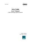

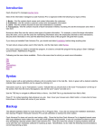
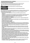
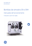

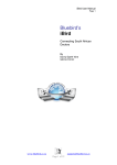


![NTT Web Hosting Service [User Manual]](http://vs1.manualzilla.com/store/data/005951289_1-c9e52ec4d0c5755656361886eb8624e9-150x150.png)