1
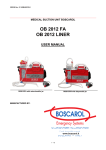
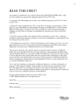
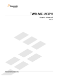
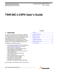
DIS-1 Dosimeter
USER’S GUIDE
Document Number 2096 6058
Version 1.04
TABLE OF CONTENT
INTRODUCTION..................................................................................................3
TERMINOLOGY ..................................................................................................4
THE CONSTRUCTION........................................................................................... 7
THE OPERATION ................................................................................................. 8
HARD RESET PROCEDURE ................................................................................... 9
WEARING THE DIS-1 DOSIMETER .................................................................... 10
MAINTENANCE AND CALIBRATION ..................................................................... 9
Calibration ................................................................................................... 11
Cleaning of the electrical contacts ................................................................... 11
Cleaning/decontamination .............................................................................. 11
Drying of DIS-1 ............................................................................................ 12
SPESIFICATIONS .............................................................................................. 12
2(15)
DIS-1 User’s Guide
Ver. 1.04/MKV/MW
INTRODUCTION
The new RADOS DIS-1 personal dosimeter is based on an ionisation chamber combined with a
modern electronic Direct Ion Storage (DIS) memory cell. The Ion chamber is
widely used as a reference detector in radiation detection and is now available in
everyday dosimetry applications. The DIS-1 dosimeter could be described as a
passive electronic TLD or Film badge, which can be read infinitely and nondestructively without any loss of dose information. This unique feature allows the
user of the DIS-1 to instantly read his/her accumulated doses whenever
necessery. The DIS-1 badge has a small, lightweigth, rugged and watertight
construction, which makes the DIS-1 badge reliable and easy to use.
The radiological range of the DIS-1 covers the entire Hp (10) and Hp (0.07)
photon and beta energies without any compromises. The wide dose and energy
range, the ability to operate in pulsed fields and the performance at high dose
rates make DIS-1 an ideal device for all kinds of radiation dosimetry applications.
The DIS-1 allows for the detection of heavy, high-energy ions and its immunity to
any external interference is unequalled. There are no deviations in the dose
readings even at very high EM or RF fields.
Figure 1
The excellent radiological features and the easy and fast reading of the DIS-1 dosimeter make the
new DIS based RADOS dosimetry system superior to any Film dosimetry or TLD system without
the need for complicated processing systems.
The doses in the DIS-1 dosimeter DIS-1 are read using the DBR-1 (DIS Badge Reader). To obtain
the most recent dose values of Hp(10) and Hp(0.07), the user simply plugs the dosimeter into the
reader head and the values are displayed in the display of the reader in a few seconds. The reader
can be operated in various modes . It can be set in a stand alone mode where the reader only
performs the measurements and displays the doses OR it can be set as a system reader device for
the WinELD dosimetry system, providing the range of the dose management features. The system
can be connected to a PC either using the RS-communication port or the local area network port
(LAN).
The instant reading capability of the dosimeter allows the user to observe the accumulated doses
even on a daily basis. This property makes the DIS-1 practical when eliminating unnecessary doses
(principle of ALARA = As Low As Reasonably Achievable), something that is not possible with other
types of passive dosimeters such as: Film, TLD or OSL where the accumulated dose is revealed
once per month or less frequently. Combining the features of unlimited dose read-outs together
with the possibility of storing dose information automatically into a database every time a read-out
is performed means that up-to-date information of doses is always available and the concept of the
control period has a completely new approach. While other passive dosimeters require to be sent to
a specific laboratory for read-outs once per month or once per three months (once within a control
period) the DIS-1 can be read locally with only the data being sent forwards. The dosimeter needs
to be sent to a laboratory only if the required check-out period has elapsed or the accumulated
dose has reached a pre-determined threshold value. This means that the amount of the manual
labor required in handling the dosimeters on a regular basis is decreased significantly.
With the sensitivity of the DIS-1 dosimeter and the versatility of the DBR-1 reader either in standalone or entry/exit reader mode, the ELD system is ideal for all types of control and/or legal
dosimetry applications.
The DIS-1 has the added flexibility of storing and measuring/recording
a) The total dose received to the badge since the last Hard Reset/Calibration
b) The assignment Dose of the user since the issuing date, as well as
c) The session dose measurement
This feature allows the dose record to be kept for legal dosimetry reporting, but allows the
dosimeter to be reset and to receive doses for either specific time periods (Day, Week, Month) or
specific tasks. DIS-1 also makes it possible to optimize the TOTAL number of dosimeters required
in a session where the number of controlled individuals changes due to the fact that issuing the
dosimeter to a new person is easy.
3(15)
TERMINOLOGY
The following table summarizes some of the most frequently used terms of DIS-technology:
DIS
Direct Ion Storage: This describes the basic method of operation,
the charge or the ions are stored directly in the analog memory
element.
Some of the dosimeters are entirely or partially based on this DISmeasurement method. The first is the DIS-1, which has now been
followed by the DIS-2 and RDD-20 products.
DIS-1
Dosemeter (also Dosimeter);
Direct Ion Storage Detector / Gamma & Beta & X-Ray Detector.
Standard measuring element.
The DIS-detector is a combination of an Ion Chamber (IC) and an
Analog Memory Element (AME) that converts the charge induced
by the dose in the ionizing chamber into an electronically readable
voltage information.
DBR
Dosemeter Badge Reader (DIS Badge Reader)
A reading device that measures the dose dependent voltage and
converts it to the corresponding dose of the element.
Element
The Element is the basic detection unit within the DIS-based
product. There can be several elements inside one DIS-product
with different types of sensitivities or mechanical constructions
meaning that the elements are able to measure different types of
radiation. Occasionally this element is referred to as a channel or a
chamber. Currently there are two main types of elements in use:
The DIS-detection element and the MOSFET-detection based
element.
There are five elements in the DIS-1: three DIS-elements and two
MOSFET-elements. The elements are : DS, DL, DH, SL and SH.
These are symbolical names, where the D stands for ‘Deep Dose’
element (Hp(10)) and the first letter S stands for ‘Shallow/Skin
Dose’ element (Hp(0.07)). The second letter gives the approximal
dose measuring range:
S (Sensitive Range) = 0 … 4000 µSv
L (Low Range)
= 0 … 1000 mSv
H (High Range)
= 0.1 … 40 Sv
Channel
Channel is for connecting the element with the measuring
electronics. Sometimes this term is used instead of the term
‘element’. It should not be mixed with a channel of the
spectrometer.
Chamber
The chamber can be assumed to be a cavity filled with gas and
surrounded by walls (an ion chamber). This term has been used
occasionally when discussing one element of the DIS-1.
MOSFET
This is a special type of an element, where the radiation detection
is based on the measurement of the VGS-parameter of the MOSFET
transistor.
Hard Reset
Hard Reset is a procedure, where the physical state of the dose
information of the memory element is changed with a special
procedure. This means that the charge, which has been stored in
the AME, is set to the zero dose state. This procedure is
irreversible once it has been completed.
4(15)
DIS-1 User’s Guide
Ver. 1.04/MKV/MW
Assignment Reset
“ARD,i”
Session Reset
“SRD,i”
Assignment Reset is performed when the dosimeter is given to a
new user (assigned or issued). This occurs at the start of the
control period. The performed reset is a purely “digital operation”,
where the currently measured dose information is stored into a
digital memory of the dosimeter for each corresponding element.
The successive dose read-outs are compared to these stored
values and the difference is indicated. The procedure does not
change the physical state of the elements.
Session Reset is an operation, where the new offset dose is
measured and stored in the digital memory of the DIS-1. The
measurements are later compared to these stored offset values to
give the current doses.
Other naming conventions are: Virtual Reset, Soft Reset or Offset
Calculation.
Total Dose
“DT,i”
Assignment Dose
“DA,i”
Measured internal Dose value of element “i” is DT,i
DBR gives
Hp10 DA,DEEP
Hp07 DA,SKIN
Dose Displayed DA,i = DT,i - ARD,i
Session Dose
“DS,i”
DBR gives
hp10 DS,DEEP
hp07 DS,SKIN
Dose Displayed DS,i = DT,i - ARD,i - SRD,i
Generation
Generation is a unique digital signature information that is used to
specify the physical and logical parameters of the dosimeter. It
describes possible special features of the dosimeter to the reader
and system (memory size, filtration of MOSFET elements and PTB
approval).
PRINCIPLE OF DIRECT ION STORAGE
In the original non-volatile solid-state memory cell, information is stored in the form of an
electronic charge trapped in the floating gate of a MOSFET transistor. Originally the memory was
used only to store digital information. In practical applications this means that the signal “1” is
read from a memory cell when the charge exceeds a certain threshold value. In the new type of
non-volatile memory, the amount of the charge in each memory cell has been made fully variable,
which in turn controls the output signal of the element. Now the memory cell can be used to store
analog information.
Figure 2 shows the structure of a standard Analog-EEPROM memory cell. The charge in the floating
gate can be set to a predetermined level by tunnelling electrons through the oxide layer. The
charge is then stored permanenty in the gate due to the fact that in the normal operating
temperature range the electrons have a very low probability of exceeding the energy barriers in the
metal-oxide and oxide-silicon interfaces. A high purity level is essential in the silicon dioxide
formation process during the manufacture of these devices to free the oxide in any mobile charge
carriers, of which Na-ions are usually the most dominant. Today it is possible to manufacture
memory cells that are capable of retaining a stored charge for hundreds of years
5(15)
Reading the stored information is carried out by
measuring the channel conductivity of the
transistor without disturbing the stored charge.
In order for the ionising radiation to have an
effect on the stored charge, either a new charge
has to be brought to the gate or an existing
charge be removed. Ionising radiation incident on
the oxide layer will produce electron-ion pairs but
due to the very low mobility of the charge
carriers in the oxide, recombination occurs with a
high efficiency and most of the free charge is
neutralised before it is able to pass the metaloxide interface. Therefore MOS dosimeters, which
are based on this principle, have a very low level
of sensitivity to ionising radiation and are not
sensitive
enough
for
radiation
protection
applications.
Control gate
Floating gate
Electron
tunneling
paths
Oxide
Source
Drain
Channel
Figure 2 Analog EEPROM memory cell
l
In the DIS dosimeter the oxide layer surrounding the floating gate has an opening allowing the
surface of the floating gate to be in direct contact with the surrounding air (or any other gas). Now
any ionising radiation incident in the air or gas produces electron-ion pairs with extremely high
mobility and in case there is an electric field surrounding the floating gate, these charge carriers
will be transferred efficiently to the gate before any recombination occurs.
The structure of the DIS memory cell is illustrated in Figures 3-4.
Floating gate
Opening
Oxide
Source
Electron
tunneling
path
Air or Gas
Drain
Channel
Figure 3 A DIS memory cell surrounded
by a conductive wall
Figure 4 A DIS memory cell
The ion chamber is effectively formed between the wall and the floating gate by surrounding the
entire structure with a conductive wall as illustrated in Figure 3. For photon radiation, the initial
interactions take place in the wall material and the formed secondary electrons ionise the air or gas
between the wall and the gate. If the wall is sufficiently thin, the charged particles are allowed to
transfer all or part of their energy directly into the air or gas space.
6(15)
DIS-1 User’s Guide
Ver. 1.04/MKV/MW
THE CONSTRUCTION
The DIS-1 badge consists of two parts; the DIS-1 dosimeter and the DDH holder with a clip. The
dosimeter can be easily removed from the DDH-2 snap-on holder. Figures 5-6 show the front and
the reverse side of the DIS-1 dosimeter. There is a beta window in the round area in the upper left
corner of the dosimeter In order to allow the beta particles to penetrate the filter and enter the
chambers, the beta window filter is made of a thin foil*.
Normally the holder protects the
electrical connector in the back of the DIS-1 dosimeter.
Beta window
Reference Point
Connector
Figure 6
Figure 5 The DIS-1 front view
and back view
*PLEASENOTE THAT TOUCHING THE BETA WINDOW WITH A SHARP ITEM MAY
CAUSE DAMEGE TO THE DOSIMETER. THIS AREA MUST NEVER BE OBSCURED.
THE FIVE MEASUREMENT CHAMBERS
The five elements of the DIS-1 are positioned
inside
a
hermetically
sealed
housing
measuring 41x44 x12 mm (Figure 7). The
weight of the DIS-1 dosimeter without the
holder is approx. 24 g. Three of the five
elements are DIS based ionization chambers
and two are MOSFET detectors. The DSelement for the Hp(10) dose has a measuring
range from 1µSv to 4000 µSv. The DL- and
SL-elements for Hp(10) and for Hp(0.07)
respectively have measuring ranges from
0.01 mSv to 1000 mSv. The DH- and SHelements are MOSFET transistors measuring
doses above 1.0 Sv up to 40 Sv. A regular
check of the dosimeter is required when a
dose
of
10
Sv
is
accumulated.
Figure 7 The five chambers of DIS-1
The Measurement ranges and resolutions of the different elements:
Element
DS
DL
DH
SL
SH
* Check every 10 Sv
Range
1 … 4000 µSv
4 … 1000 mSv
1.0 Sv … 40 Sv *
0.01 … 1000 mSv
1.0 … 40 Sv *
Generation 9 and older
1 ... 4000 µSv
4 ... 500 mSv
0.5 ... 40 Sv *
0.01 ... 500 mSv
0.5 ... 40 Sv *
7(15)
Resolution of display
1 µSv
0.01 mSv
100 mSv
0.01 mSv
100 mSv
THE OPERATION
All the chambers of the DIS-1 measure continuously. It is not possible to switch off any of the elements.
When the received dose exceeds the maximum of the range of the DS-element, the readout is continued
with the DL-element. When the dose of the DL-element exceeds the maximum of the range, the readout is switched to the DH-element. The same applies to the SL and SH elements.
Resetting the dose of the DIS-1 using the DBR-1 reader can be carried out in three ways. In the Session
Reset, the current dose reading is stored in the DIS-1 internal memory and subtracted from the total
dose upon a read-out. In this case the stored physical dose information is not lost but can be recalled at
any time with the DBR-1 reader. It is recommended to use the Session Reset only when the accumulated
dose is low and there is a need to reset the dose frequently (daily or weekly).
The Assignment Reset should be used only when the dosimeter is issued to a new user. The Assignment
Reset does not perform the physical hard reset but enables the reader to operate as if the hard reset
were performed.
In order to remove the dose permanently from one or more of the elements, a Hard Reset is performed.
The Hard Reset removes the charge physically from the floating gate of the detector memory element.
The Hard Reset should only be used when necessary. The Hard Reset is controlled by the DBR-1 after the
user has activated it. The DBR-1 will not perform the Hard Reset if the accumulated dose is less than the
predetermined threshold dose. This threshold dose element is element dependent and is approx. 15% of
the maximum of the range for the DS element, and approx. 2% of the maximum of the range for the
DL/SL elements. If any successive hard resets are attempted, only the assignment reset will be
performed. An annealing shall be performed after a hard reset.
As stated earlier, there are five elements in DIS-1. The elements are : DS, DL, DH, SL and SH. The DH
and SH elements are constructed according to a design, which makes it impossible to perform the Hard
Reset.
Figure 8. gives two types of information. Firstly, it illustrates how the measuring ranges of all the
elements are located within the total measurement range of the DIS-1. This means that when the DIS-1
is set to measure the Hp(10) dose quality from 0 to 40 Sv, the range is measured using the information
from three separate DIS-1 elements. Secondly, the picture illustrates the sub-parts of all the element
measurement ranges. The DBR-1 reader treats these sub-parts differently during the Hard Reset
procedure.
As illustrated in Figure 8 , the measuring range of the DS, DL and SL channels are divided into three subparts: the “No Hard Reset” -range, the “Normal” -range and the “Hard Reset” -range. There is also a
“MOSFET” –range. These sections are described as follows:
NonHR range
Recommended Range
HardReset range
MOSFET range
Graphical representation of DIS-1 measurement ranges.
SH
SL
DH
DL
DS
0,001
0,01
0,1
1
10
100
1000
Dose (mSv)
Figure 8 DIS-1 measurement ranges for various chambers
8(15)
10000
100000
DIS-1 User’s Guide
Ver. 1.04/MKV/MW
Sections of range
“No Hard Reset” -range: the reader DBR-1 does not perform any physical Hard Reset actions if
the total dose is within this range. The assignment dose display is set to zero when the current
dose value is set as the new reference point. The element that is not Hard Reset will be
treated as in the case of the Assignment Reset.
“Normal” -range: In typical applications the Hard Reset is not necessary within this range. In
some special cases it may be beneficial that the Hard Reset is performed within this sub-part.
If the following three conditions are met: 1) The expected dose accumulation is greater than 1
mSv / one work operation. 2) the highest deep dose resolution is required. 3) The total dose
of the DS-element is close to 3 mSv. If these conditions are met, it is possible to perform a
Hard Reset even if the total dose is still within the “Normal” –range.
The “Hard Reset” -range: When the total dose of a channel is within this range, it is advised to
perform the Hard Reset.
The “MOSEFET” –range: This is the measuring range of the DH and SH elements. These
elements are constructed according to a design that makes it impossible to perform a hard
reset. The detection methodology is different from the other elements.
NOTE: the operational range of each element is the total range defined by these sub-parts.
Each measuring application is a unique method and the execution of the Hard Reset has to be
determined according to the case at hand.
HARD RESET PROCEDURE
After carrying out the hard reset in the DBR-1 reader, it is required to anneal the dosimeter at a
temperature of 60-65 oC for a period of 4 hours after the hard reset. The reset assignment function
should be performed when the DIS-1 has cooled down to room temperature. If the reset function
assignment is performed immediately after the hard reset without any annealing, a small dose of approx.
a few hundred µSvs may remain in the DIS-1, depending upon the element.
-
Hard Reset the DIS
-
anneal DIS-1 at 62.5 ± 2.5 ° C at least 4 hours, max.48 hours;
preferably 16 hrs.
-
cool down to room temperature at least 1 hour
-
perform an assignment reset to DIS
Longer annealing times and cooling times may be used to assure a more stable performance.
The Maximum annealing time of 2 days @ 65°C should not be exceeded.
The Maximum temperature of 70°C shall never be exceeded.
9(15)
WEARING THE DIS-1 DOSIMETER
The DIS-1 badge is supplied with a clip. It is recommended to wear
the DIS-1 dosimeter on the chest on top of the clothing. Special
attention should be paid at having the beta window of the dosimeter
opposite the body side (see Figures 9-10). Although the DIS-1 has a
rugged and watertight construction, the best measurement results
will be achieved with careful handling of the dosimeter.
Figure 9 Wearing the DIS-1 badge
Figure 10 The body side of the holder
10(15)
DIS-1 User’s Guide
Ver. 1.04/MKV/MW
MAINTENANCE AND CALIBRATION
Calibration
The DIS-1 is calibrated with a sophisticated automatic system. The calibration values are not
expected to change during normal use.
In case the radiological calibration coefficients require to be adjusted, an optional software and
maintenance calibrator may be used.
During the calibration, the calibration factors for one or more
of the elements may be set.
Cleaning of the electrical contacts
If the dosimeter is used in a dusty environment, it is important to clean the
connector contacts regularly before making any read-outs. The cleaning
should be carried out immediately if there are any problems with reading
the dosimeter in the DBR-1 reader. Remove the DIS-1 element from the
holder for the cleaning of the connector area (Fig. 11). Use a soft cotton
swab and ethanol to clean the connector.
Note: To preserve the connectivity of the gold plated contacts, it is not advisable
to use any excessive mechanical or abrasive cleaning methods.
Cleaning/decontamination
DIS-1 has a hermetically sealed metal case made of aluminum, a polyimide
window for the Hp(0.07) measurements and gold plated reading contacts.
The holder of the DIS-1 is made of anodized aluminum and includes a
stainless steel contact protection spring, a locking spring and a plastic part
with a nickel-plated clip construction.
The following items are required during the decontamination procedure:
Figure 11
- Cleaning solution with neutral pH (non-corrosive preferred)
- A cotton swap, paper tissue, etc.
Check that the surface of the DIS-1 window is smooth and that is has a concave shape at normal
room temperature. This indicates that the DIS-1 is still hermetically sealed. Should the surface be
extensively ruffled it is possible that the DIS-1 is mechanically damaged. It is not advisable to
place the DIS-1 into the decontamination solvent before the mechanical properties have been
checked.
Should there be any adhesive residues from labels or tapes on the surface of the DIS-1 or holder,
it is advisable to clean the surfaces with a suitable solvent. Any adhesive residues on the window
of the DIS-1 should be left untouched to avoid any possible damage to the filter. It must be noted
that any labels over the window may decrease the performance of the beta and low energy
photon measurements.
If the dosimeter is only ‘dry-cleaned’, it is not necessary to remove the DIS-1 from the holder.
When the unit is decontamined by immersing it into a solution, it is advisable to remove the unit
from the holder to prevent any of the decontamination solution and water from remaining
between the holder spring and the holder, which might cause stability or corrosion problems in
the long run.
Remove the DIS-1 from the holder and decontaminate the DIS-1 and the holder separately.
Immerse the DIS-1 into the decontamination solution for a couple of minutes. The temperature of
the solution should be approx. 30 - 35 °C. To increase the cleaning effect, the DIS-1 may be
shaken while immersed in the solution. Ultrasonic cleaning is not recommended as it may harm
the beta window of the DIS-1.
After washing, remove the DIS-1 from the solution and allow any excessive solution to drip back
into the washing container. (If in holder: Open the protective steel spring by inserting the DIS-1
in a special tool.) Wipe the contact area with a cotton pad. Do not use excessive force while
wiping.
11(15)
Rinse the DIS-1 thoroughly by first using water in a suitable container (to dissolve any possible
contamination into the water) and finally under running water. Any remaining decontamination
solution should be wiped from the surfaces of the DIS-1.
Drying the DIS-1
Dry the DIS-1 with soft tissue. Place the DIS-1 in an oven at +50 °C for 16 hours. Use purified
alcohol and a cotton pad to wipe the contact area.
When drying the holder of the DIS-1, use e.g. a cool air blower to dry the water on the surface
of the holder. Use soft tissue to dry the parts of the holder and place the parts in an oven.
SPECIFICATIONS
Radiation detected:
Detector type:
Energy range:
Dose
measurement range:
Gamma-, x-ray and beta.
Three* TMDIS (Direct Ion Storage) detectors, and two* MOSFET detectors.
Hp(10):
Hp(0.07):
15 keV-9 MeV.
photons 6 keV and higher
beta: 240 keV-2.2 MeV.
10 µSv to 1 Sv
1 µSv to 1 Sv
(1 mrem to 100 rem).
(0.1 mrem to 100 rem).
partially up to **40 Sv (4000 rem).
partially up to **40 Sv (4000 rem)
± 5 % at 1 mSv Cs-137.
± 10 % at 10 mSv Cs-137.***
± 30 % between 15 keV-9 MeV.
± 30 % for photons 6 keV and higher.
(e.g. Cs-137, Average 662 keV)
+10…-50% for beta,
E,mean=200-800 keV
± 20 % up to 60° at 65 keV.
± 20 % up to 60° at 65 keV.
6 months.
(5 years for Hp(10) below 5 mSv.)
No external power needed for measurement.
Through a 14-pin connector with a DBR dosimeter reader.
Operation: -10 ºC - +50 ºC.
Annealing: up to 65 ºC, max 48 h per reset.
Storage: -20 ºC - +60 ºC.
Up to 90% relative humidity.
Resistant to static discharge, RF-interference and magnetic fields, and EMP.
Withstands multiple 1 meter drops onto concrete. An anonized aluminum
snap-on holder.
IP 67 (waterproof).
41 x 44 x 12 mm3, in holder 47(95) x 49 x 13 mm3.
24 g (in holder 43 g).
.
Calibration accuracy:
Energy response:
Directional response:
Maximum possible
measurement time: ****
Power supply:
Dose read-out:
Temperature range:
Operational humidity:
Casing:
Enclosure class:
Dimensions:
Weight:
ATTENTION ! The DIS-1 Dosemeter does not contain any hazardous substances and can be recycled
accordingly.
*) The number of the chambers per type may vary with the generation of DIS-1.
**) Non-resetability, limited energy range.
***) With a 6 mm build-up plex at distance of 15 cm in front of the dosimeter.
****) tMAX as specified in the IEC 61066 standard.
12(15)
DIS-1 User’s Guide
Ver. 1.04/MKV/MW
Range of DIS technology based products
Order number:
1237-002
DIS-1 without holder
1237-003
DDH-1 holder with permanent attachment (one time usable)
1237-004
DIS-1 + DDH-1
1237-006
DBR-1 Dosimeter Reader (Firmware release Ver.1.17.xx for
WinELD)
1237-017
DDH-2 snap-in-holder for DIS-1
1237-019
DIS-1 + DDH-2
1237-020
RDC- software
1237-021
WinELD Light software, system licence
1237-025
WinELD software, Client licence
1237-028
Maintenance Calibrating SW for DIS-1
1237-032
WinELD Pro software, system licence
1237-033
DBR-2 Dosimeter Reader (Firmware release Ver.1.17.xx for
WinELD)
13(15)
FEEDBACK FORM
We are continuously working hard at supplying you with correct and easy-to-read technical
documents. However, complex systems are often difficult to document, describe and
understand, and mistakes and inadequacies may occur occasionally during the documentation
process. We would like to hear your opinion on this document and to correct any possible
errors.
If you have spotted errors or should you find any part of the document unclear, please let us
know. Make a copy of this page, describe the problem and send it to RADOS.
To:
Mirion Technologies (RADOS) Oy/Technical Documents
P.O. Box 506, FIN-20101 Turku, Finland
Fax: +358-2-468 4601
This way you will help us in improving our documents and thus supplying you with better
documents.
The best feedback will be rewarded.
Notes on this document
Name of the document:
Issue date:
Description of the mistake or problem
Correction
Page no.
Notes on the product
Name of the product:
Description of the mistake or problem
Version or model:
Correction
General Notes
If you need more room, please use attached pages.
Name:
Company:
Address:
Position:
Telephone:
Telefax:
14(15)
DIS-1 User’s Guide
Ver. 1.04/MKV/MW
15(15)