1
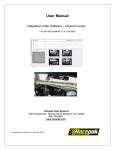
G2X Pro Installation Manual
G2X Pro Installation and User Manual
2006 - G2X Pro Manual V1.0
Racepak, G2X Pro, Racepak G2X and Vnet are trademarks of Competition Systems, Inc. /Racepak
© Competition Systems, Inc. /Racepak
1
Disclaimer
Competition Systems, Inc/Racepak make no representations or warranties of any type with
respect to the contents in this manual. Competition Systems, Inc/Racepak disclaim any implied
warranties or fitness for any particular purpose. Competition Systems, Inc/Racepak is not liable
for any errors contained within or for incidental or consequential damages in connection with the
supply, performance or use of the hardware and software or this manual.
Competition Systems, Inc/Racepak reserve the right to revise this installation and user manual at
any time, without obligation to notify any person of revisions.
Warranty
Competition Systems, Inc/Racepak make every effort to insure our products and services are of
the highest quality and standards. It is our intention to maintain a mutually beneficial and cordial
relationship with each and every customer.
Competition Systems, Inc/Racepak warrants all merchandise manufactured by Competition
Systems, Inc/Racepak against defects in workmanship or material for a period of six months
after the data of purchase. This warranty applies to the first retail purchaser and covers only
those products exposed to normal use or service. It does not apply to those products used for a
purpose for which said products were not designed, or which has been altered in any way that
would be detrimental to the performance or life of the product, or misapplication, misuse,
negligence, or accident. Any part or product found to be defective after examination by
Competition Systems, Inc/Racepak will be repaired or replaced. Competition Systems,
Inc/Racepak assumes no responsibility for diagnosis, removal and/or installation labor, loss of
vehicle use, loss of time, inconvenience or any other consequential expenses.
This warranty is in lieu of any other expressed or implied warranties, including any implied
warranty or merchantability or fitness, and any other obligation on the part of Competition
Systems, Inc/Racepak, or selling dealer.
If you have any questions regarding warranty, please contact customer service at Competition
Systems, Inc/Racepak.
2
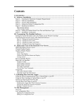
G2X Pro Installation Manual
Disclaimer ................................................................................................................ 2
Warranty ................................................................................................................... 2
Overview .................................................................................................................. 8
What is the G2X Pro?.......................................................................................................................................................8
Design Features .................................................................................................................................................................9
Factory tested........................................................................................................................................................ 9
Custom setup file.................................................................................................................................................. 9
Simplified setup.................................................................................................................................................... 9
Motorsports specific software ............................................................................................................................. 9
Vnet and Analog External Sensor Channels ...................................................................................................................9
Vnet....................................................................................................................................................................... 9
Analog................................................................................................................................................................... 9
RPM: ..................................................................................................................................................................... 9
Technical Specifications.................................................................................................................................................10
Items Included With the G2X Pro Package PN 600-KT-G2XPRO ............................................................................11
Sensor Package Options .................................................................................................................................................11
Display Dash Options .....................................................................................................................................................11
Installation .......................................................................................................................................................................12
G2X Pro Functions .........................................................................................................................................................12
G2X Pro Configuration File...........................................................................................................................................12
Logging Start and Stop ...................................................................................................................................................12
Download Data................................................................................................................................................................12
DatalinkII Software.........................................................................................................................................................12
PC Minimum Requirements...........................................................................................................................................12
Terminology....................................................................................................................................................................13
Hardware Installation............................................................................................. 14
Sensor Package Installation Manuals ............................................................................................................................15
System Installation Schematics......................................................................................................................................15
G2XPro with Display Dash and 620-KT-STBB Package ...............................................................................16
G2XPro with Display Dash and 620-KT-STBB Package ...............................................................................17
G2XPro with UDX Display Dash, 620-KT-STBB, 620-KT-4SHOCK and 620-KT-RIDEHT Packages...18
Adding Additional Vnet Sensors ...................................................................................................................................19
Engine RPM and Power Input........................................................................................................................................20
Power / Engine RPM Cable...............................................................................................................................20
Mounting Location of Logger ........................................................................................................................................21
Heat .....................................................................................................................................................................21
Electrical Interference ........................................................................................................................................21
Moisture ..............................................................................................................................................................21
Easy Access ........................................................................................................................................................21
Movement ...........................................................................................................................................................21
Mounting Orientation of Logger....................................................................................................................................22
Mounting Method ...........................................................................................................................................................22
Power Supply and Grounding ........................................................................................................................................23
Engine RPM Signal.........................................................................................................................................................23
SD Memory Card Installation ........................................................................................................................................23
GPS Antenna Mounting..................................................................................................................................................24
GPS antenna mounting for stock bodied vehicles............................................................................................24
GPS antenna mounting for open wheel vehicles..............................................................................................24
3
Connection of the GPS antenna to the G2X.....................................................................................................24
GPS LED Display ...........................................................................................................................................................25
System Installation Order ...............................................................................................................................................26
Datalink II Software Installation .......................................................................... 27
Data Download Path .......................................................................................................................................................27
Downloaded Data...............................................................................................................................................27
Configuration File ..............................................................................................................................................27
DatalinkII Software............................................................................................................................................27
Computer Requirements .................................................................................................................................................28
PC Hardware Requirements ..............................................................................................................................28
Screen Resolution...............................................................................................................................................28
PC Software Requirements................................................................................................................................28
Software Installation .......................................................................................................................................................29
License Disk Installation ................................................................................................................................................30
SD Flash Card Reader Installation.................................................................................................................................30
DataLink II Help Files ....................................................................................................................................................31
Demo Run Data File .......................................................................................................................................................31
Serial Com Port Settings ....................................................................................... 32
USB to Serial Adapter COM Port Number Setting............................................. 33
Configuration File.................................................................................................. 34
Motorsports Specific Configuration Files............................................................ 35
Circletrack and Road Racing.............................................................................................................................35
Boating................................................................................................................................................................35
Pulling .................................................................................................................................................................35
Standard ..............................................................................................................................................................35
Setting a Default Configuration .....................................................................................................................................36
Modifying the Data Logger Setup ........................................................................ 37
PC Configuration Changes .............................................................................................................................................37
Write or Send to the data logger........................................................................................................................37
Data Logger Configuration Changes .............................................................................................................................37
Read the data logger Configuration ..................................................................................................................37
Adding or Removing Sensors - Reading the Configuration.........................................................................................38
Modifying the Configuration File..................................................................................................................................39
Writing or Send the Configuration ................................................................................................................................40
Configuration File Details..................................................................................... 41
Circletrack and Road Racing Configuration File..........................................................................................................41
Factory Defined Shock and Ride Height Channels: ........................................................................................41
Factory Defined Math Channels: ......................................................................................................................41
Shock Velocity................................................................................................................................................................41
Ride ..................................................................................................................................................................................41
Pitch .................................................................................................................................................................................41
Pre-Defined Difference Channel:......................................................................................................................42
Circletrack and Road Racing Runlog Pages..................................................................................................................43
Session Info and Weather ..................................................................................................................................43
Map Setup...........................................................................................................................................................43
4
G2X Pro Installation Manual
Map Analysis......................................................................................................................................................43
Histograms..........................................................................................................................................................44
Real Time Displays ............................................................................................................................................44
User Defined Runlog Pages...............................................................................................................................44
Car Setup.............................................................................................................................................................45
Exporting the Start / Finish Position Runlog Page .......................................................................................................46
TrackVision Export Runlog Page ..................................................................................................................................47
Boat Racing Configuration.............................................................................................................................................48
Pre-Defined Math Channels: .............................................................................................................................48
Prop Speed.......................................................................................................................................................................48
Prop Slip ..........................................................................................................................................................................48
Pre-Defined Difference Channels .....................................................................................................................49
Boat Racing Runlog Pages .............................................................................................................................................50
Session Info and Weather ..................................................................................................................................50
Map Setup...........................................................................................................................................................50
Map Analysis......................................................................................................................................................50
Prop Data and Accel Reports ............................................................................................................................51
Real Time Displays ............................................................................................................................................53
User Defined Runlog Pages...............................................................................................................................53
Exporting the Start / Finish Position Runlog Page .......................................................................................................54
TrackVision Export Runlog Page ..................................................................................................................................55
Puller Runlog Pages ........................................................................................................................................................56
Session ................................................................................................................................................................56
Pull Info ..............................................................................................................................................................56
Weather ...............................................................................................................................................................56
Vehicle and Track Info ......................................................................................................................................56
Dash Gauges .......................................................................................................................................................56
User Defined Runlog Pages...............................................................................................................................56
Making the Initial Run........................................................................................... 57
Transferring Data ............................................................................................................................................................57
Session Dialog Window .................................................................................................................................................58
Map Select Dialog Window ...........................................................................................................................................59
Puller Run - Setting the Zero Start Point - Very Important..........................................................................................61
Create Trackmap (Closed Course) Oval and Road Racing ..........................................................................................62
Step 1: Select / Create GPS Map .....................................................................................................................63
Step 2: Select Track Type..............................................................................................................................................64
Step 3: SET LAP START ................................................................................................................................64
Step 4: Create GPS Track Map ........................................................................................................................64
Track Map Creation (Open - Autocross, Solo & Hill Climb)......................................................................................65
Step 2: Select Track Type.................................................................................................................................65
Step 3: Set Lap Start .........................................................................................................................................65
Set Lap End (Open Course Only) .....................................................................................................................65
Step 4: Create GPS Track Map ........................................................................................................................65
Add Map Segments - Closed Course Tracks Only .......................................................................................................66
Step 1: Open Lap ..............................................................................................................................................66
Step 2: Generate Segments...............................................................................................................................66
Step 3: Manually Edit Segments ....................................................................................................................................66
Step 3: Manually Edit Segments ....................................................................................................................................67
Add Inside / Outside Track - Optional ..........................................................................................................................68
Step 1: .................................................................................................................................................................68
Step 2: .................................................................................................................................................................68
Manually Loading GPS Track Maps .............................................................................................................................69
5
Opening a Lap and Graphing Data ....................................................................... 70
Open a Lap ......................................................................................................................................................................70
Distance Mode Graphed Data ........................................................................................................................................71
Speed and Segment Reports ...........................................................................................................................................72
Overlay (Graphing) Multiple Files ................................................................................................................................73
Advanced features of the DataLink II Software .................................................. 74
Runlog Pages - Data Comparison in Report Format ....................................................................................................74
Reference and Main Settings for Runlog Data Comparison ........................................................................................75
Graph Scaling Explained ................................................................................................................................................76
Graph Scaling Values Changed per Channel ................................................................................................................77
Chart Scaling Sets - Universal Scaling Settings ...........................................................................................................78
Creating Graph Sets for Display - Quick Graphs .........................................................................................................79
How to Determine the Currently Graphed and Active Channel ..................................................................................80
Averaging Data Using the Averaging Cursor Action ...................................................................................................81
Graphing Data from an Entire Run................................................................................................................................82
Zoom Command .............................................................................................................................................................83
Viewing Real Time Data (Telemetry) on your PC .......................................................................................................84
Setting up the Logger Real Time Telemetry Parameters.................................................................................84
Entering the DataLink Telemetry Parameters ..................................................................................................85
Starting a Telemetry Session .............................................................................................................................86
Troubleshooting and FAQ .................................................................................... 88
No Data Obtained During Run.......................................................................................................................................88
Download Error Received When Download is attempted ...........................................................................................88
User’s PC will not communicate with the data logger, using the serial cable ............................................................88
Does GPS Always Work? ..............................................................................................................................................89
Will Rain Affect the GPS Signal?..................................................................................................................................89
Can I Acquire Elevation? ...............................................................................................................................................89
Does the Loss and Gain of Satellites Affect the Data?.................................................................................................89
Speed Accuracy?.............................................................................................................................................................89
Laptime Accuracy? .........................................................................................................................................................89
GPS Data Does Not Start Until Later in the Run..........................................................................................................89
Track Mapping Accuracy? .............................................................................................................................................90
Can I install a larger Memory Card? .............................................................................................................................90
How can I email a Runfile or Trackmap? .....................................................................................................................90
Should multiple users comparing data from the same track, use different track maps? ............................................90
Lap times displayed on the dash vs. lap times from the track map?............................................................................90
I can not set Start Finish with the dash? ........................................................................................................................91
I lose satellites when I start to accelerate on the track?................................................................................................91
My data appears incorrect after downloading? .............................................................................................................91
Vnet Sensor Channels “Flat Line” during portions of the run .....................................................................................91
Vnet Sensor Channels disappear from Channel Button area .......................................................................................91
Graphed data drops to the bottom of the graph, during a run. .....................................................................................91
Excessive noise on graphed channels ............................................................................................................................91
Spikes or drop out in Wheel RPM graphed data...........................................................................................................92
Wheel RPM / Engine RPM graphed data appears high or low....................................................................................92
Beacon lap times are not received..................................................................................................................................92
Conclusion ............................................................................................................. 93
Appendix I – G2X Demo ...................................................................................... 94
PC Screen Resolution Settings:......................................................................................................................................95
6
G2X Pro Installation Manual
Opening the G2X_Demo Runfile: .................................................................................................................................96
Adjusting the Screen Sections:.......................................................................................................................................97
Adjusting On-Screen Font Size:.....................................................................................................................................98
Opening a Lap:................................................................................................................................................................99
Graphing a Data Channel: ............................................................................................................................................100
Viewing Data in Distance Mode:.................................................................................................................................101
Graphing Multiple Files (Overlay................................................................................................................................102
Remove a Data Channel from the Graph Area (Erase): .............................................................................................102
Data Comparison in Report Format (Runlog Pages):.................................................................................................103
Assigning Main / Reference File Setting: ...................................................................................................................104
Segment Time Data Comparison: ................................................................................................................................105
Closing a File: ...............................................................................................................................................................105
Advanced Features of the Datalink II Software..........................................................................................................106
Channel Grid Display: ..................................................................................................................................... 106
Average / Minimum / Maximum Channel Values:........................................................................................ 106
Understanding Graph Scaling: ........................................................................................................................ 107
Changing Scaling Per Channel:....................................................................................................................... 107
Creating Chart Scaling Sets............................................................................................................................. 108
Predefining Graph Sets for Display: ............................................................................................................... 109
Graphing Runfile vs. Lapfile Data:................................................................................................................. 110
Zoom Command:.............................................................................................................................................. 111
Runlog Pages.................................................................................................................................................................112
Session Page: .................................................................................................................................................... 113
Weather Page:................................................................................................................................................... 113
Create GPS Track Map:................................................................................................................................... 114
Add Map Segments:......................................................................................................................................... 114
Lap Zoom.......................................................................................................................................................... 115
Map Report:...................................................................................................................................................... 115
Segment Report / Segment Compare / Speed Compare: ............................................................................... 116
User Pages 1 through 3:................................................................................................................................... 117
Min Max Average Compare:........................................................................................................................... 117
Gauges: ............................................................................................................................................................. 118
Tire Temperature / Pressure Calculator Page:................................................................................................ 118
G2X Pro Instruction Manual Update Section ....................................................119
7
Overview
What is the G2X Pro?
The G2X Pro is a 44 channel, multi-purpose data logger designed for use in road racing, circle
track, driving schools, boating, off road, hill climb or any other type of motorsports that can
benefit from the use of GPS data to obtain speed, timing and mapping functions, without the
necessity of wheel speed sensors, beacon receivers or transmitters.
When utilized in closed course racing (circletrack, road racing, etc) the data logger obtains GPS
data to provide speed and lap time information to the driver. Track mapping with segment (split)
times are derived from GPS and accelerometer data and is available upon downloading to the
users PC, in addition to data provided by external sensors connected to the data logger.
When utilized for motorsports that do not require timing and track mapping information, the
G2X Pro functions as a standard 44 channel data logger, but with the unique ability to provides
an accurate method of obtaining ground speed without the use of vehicle mounted sensors.
Adding driver input, chassis or engine related sensors are simplified by G2X Pro sensor kits.
Each kit is identified by a single part number and contains all sensors, connectors and wiring
necessary for installation. Of course, any sensor offered by Racepak may be utilized by the
G2XPro along with certain customer supplied sensors.
8
G2X Pro Installation Manual
Design Features
Factory tested: Each G2X Pro data system is factory assembled and bench tested, before
shipping to the customer. This insures that each sensor is set up and functioning correctly, before
installation on the vehicle.
Custom setup file: Factory assembly allows the Racepak personnel to create a data logger
Configuration (setup) file specifically designed for each system. This Configuration file contains
all of the technical information (start logging channel settings, scaling, channel name, calibration
values, etc) for the internal data logger sensor channels, along with any external sensors ordered
with the data logger package.
Simplified setup: What this means to the customer is a much simplified installation and start up
procedure. Following installation of the hardware and software, the data system typically
requires no set up procedures, with the exception of data channels that monitor movement such
as steering, throttle, and shock or ride height sensors. Out of the box, the data system can gather
data.
Motorsports specific software: In addition, the Configuration file created for each data system is
specific to the form of motorsports in which the data system will be used, such as circletrack and
road racing, boating, pulling, etc.
Vnet and Analog External Sensor Channels
External sensors are connected to the G2X Pro by three different methods:
Vnet: Allows the user to connect up to 32 sensors to a single cable. This single cable is
connected to the Vnet port of the data logger. Data from all Vnet sensors is then transmitted by
this single cable. Vnet sensors can be installed in any order, in any location on the vehicle. Vnet
items are identified by blue coloring.
Analog: The G2X Pro contains two high speed (logging rate) ports, labeled as Analog 1-4 and
Analog 5-8. Each port allows the input of four sensors. Analog items are identified by black
coloring. Up to 4 high speed analog sensors may be connected to one port.
RPM: 12V power, Engine RPM and wheel speed sensors utilize the RPM port.
9
Technical Specifications
Total External Sensor Channels - Defined Below
44
Vnet Data Channels
Analog Channels
Digital (RPM) Channels
Internal Channels
32
8
4
Inline & Lateral Acceleration / Voltage / GPS
Accelerometer Specifications
Sample Rate
Accuracy
Minimum / Maximum Values
100HZ - 2 Axis
1% (excluding vibration affect)
+5 / -5
GPS Information
GPS logging rate
Channels
Antenna
Accuracy
Cold start / Hot start satellite sync time
4 Hz with 100HZ inertial assistance
16
High Gain / Active
2.5 Meters
34 seconds cold / less than 3.5 seconds hot
Memory
Minimum and Maximum SD Card Size
128MB SD Flash - Included
32MB - 2 GB
Data Writing Rate
17Kb / sec
Resolution (ADC)
Data Logger
Steering, Throttle, Brake, Brake Kit
10 bit
15 bit
Processor Speed
20MHz
Sample (Logging) Rates of Data Channels
Vnet Channels
Analog Channels
Digital Channels
100 Hz Maximum
1000 Hz Maximum
100Hz RPM / 1000Hz Timing
Power & Current
Input Voltage
Current Draw
Reverse Voltage Protection
10-16V - Less than 10V can affect sensor data
700Ma with dash & no sensors
10-20 V
Operating Temperature
32 - 140F / 0-60C
Mounting Orientation
Level left & right / Level front & rear
SD memory card facing direction of travel
Engine RPM Input
50% duty cycle, 5-18V square wave signal
10
G2X Pro Installation Manual
Items Included With the G2X Pro Package PN 600-KT-G2XPRO
Item
G2X Pro Data Logger with internal G meters
128MB SD Flash Card
Serial Communication Cable
Power / RPM Cable
GPS Antenna and Cable
DatalinkII Software
Installation Manual
Part Number
640-MS-G2XPRO
CARD-MEM-SD128
680-CA-SR-G2XP
680-CA-G2X PRO
ANTG-ANN-05
Sensor Package Options
Packages
Steering, Throttle, Brake Front & Brake Rear
Four Shock Travel Package
Four Ride Height Sensor Package
Any Racepak Vnet, Analog or Digital Sensor
Part Number
620-KT-STBB
620-KT-4SHOCK
620-KT-RIDEHT
Consult catalog or website for details
Each package contains all sensors, sensor cables and connectors. In addition, any Vnet, Analog
or Digital sensor currently offer by Racepak may be utilized by the G2X Pro. For a complete
listing of available sensors, visit our website located at www.g2xpro.com or www.racepak.com
or contact the Racepak customer service department at 949-709-5555 for a catalog. Customer
supplied sensors may also be utilized, depending upon the type of sensor and the ability to
interface with the G2XPro data logger.
Display Dash Options
Dash Name
Display Dash G2XPro (G2X “mini” style)
UDX Digital Display Dash
Part Number
640-MS-G2XPDASH
250-DS-UDX
11
Installation
The G2X Pro is the first item mounted. From that point all sensors, cables and connectors are
installed in various locations throughout the vehicle, with final termination at the G2X Pro data
logger.
G2X Pro Functions
The G2X Pro logger is the main component of the data system, as it contains the memory card
and processor, along with an internally mounted GPS board and accelerometers necessary for
track mapping, speed and timing functions. In addition, power for all external sensors and sensor
connecting ports are supplied by the G2X Pro logger.
G2X Pro Configuration File
The Configuration File sets the parameters for all sensors utilized by the G2X Pro, such as
channel name, scaling and calibration values. Following installation of the G2X Pro and external
sensors, the Configuration file and data logger are updated utilizing the DatalinkII software by
connecting the users PC to the G2X Pro data logger by means of a supplied serial cable.
Logging Start and Stop
Any active channel may be used to start logging. From the factory, the G2X Pro is programmed
to start logging at 25 GPS MPH (40 KPH) and stops logging when no speed is detected for at
least 30 seconds. A data file is written each time the vehicle exceeds the start logging speed
following at least 30 seconds of no speed, and is numbered in subsequent order (1,2,3,etc). The
start logging channel may be changed to any valid sensor channel, by the user.
Download Data
Data is stored on a 128MB SD flash card supplied with the data logger, and is downloaded via a
customer supplied SD flash card reader to the users PC utilizing the DatalinkII software.
DatalinkII Software
The DatalinkII software is used to both set up (configure) the G2X Pro data logger and provide
the ability to download and analyze data. Data stored on the SD flash card is downloaded and
converted into a format (.rpk) that is recognized by the DatalinkII software. This .rpk file is then
saved to the users PC, for analysis.
PC Minimum Requirements
Windows® 98 / ME / 2000 or XP operating system / 200MHZ (Pentium II) processor
200MB of available hard drive / 16MB of RAM CD ROM drive
Serial port or USB to serial adapter / 1024 x 768 or higher monitor resolution
12
G2X Pro Installation Manual
Terminology
In order to assist in the installation and usage of the G2X Pro, the following provides an outline
of the most commonly used words that will be encountered in this manual.
Analog Channel: Data created by the reading of a voltage change sent from a sensor
Bulkhead connector: A male-female connector mounted on a firewall, bulkhead or other area
that is between the data logger and sensors. Use of a bulkhead allows the user to pass data
through the obstacle, without the necessity of routing a cable through a hole.
Calibrate: The process of assigning values to sensor voltage output, in order to graph and
analyze the sensor data.
Canbus: The specific name of the technology utilized to create the Vnet sensor system
Channel: The input from one sensor, as defined by the data logger.
Data Logger: See Data Recorder
Data Recorder: The vehicle mounted hardware device that collects and stores data transmitted
from the sensors
Digital: A sensor or signal that has only two values, off or on such as the measuring of ignition
pulses to calculate Engine RPM
Download: The process of transferring data saved on the data logger memory card to the users
PC using the DatalinkII software, in order to graph and analyze data. Memory card data must be
downloaded through the DatalinkII software and can not be open directly from the memory card.
Filter: The process of smoothing the visual appearance of a graphed data channel.
Graph: A visual representation of sensor data, compared to time or distance
HZ: Number of times per second. Used to define logging or sample rate. Example: 4Hz
represents data that is saved 4 times (every .250) per second.
KB: Abbreviation for kilobyte, which represents one thousand bytes of information.
Logger: See Data Recorder
Logging Rate: The number of times per second, which the data logger records incoming data
from a sensor and is defined as Hertz, or Hz. Each sensors logging rate may be define by the user.
Math Channel: A data channel created from the input of an actual sensor which is then used in a
mathematical formula to create a channel available for graphical analysis
MB: Abbreviation for megabyte, which represents one million bytes of information.
Overlay: The ability to graph multiple data channels, all at the same time.
Runfile: The file created when a run is transferred from the data logger memory card to the users
PC. Configuration File
Sample Rate: See Logging Rate
SD Memory Card: Secure Digital compact flash memory card
Sensor: A device that converts a physical property, such as pressure into a voltage signal
Smooth: See Filter
Start Logging Channel: The channel that is used to start the logging process
Trace: This term is another method used to describe Graph
Transducer: See Sensor
Transducer: See Sensor
Vnet Channel: Any sensor that is connected to the Vnet port of the data logger
Vnet: Racepak exclusive that allows multiple sensors (analog or digital) to transmit their data
over a single cable, back to the data logger.
13
Hardware Installation
Logger Dimensions
External Connectors and Features
SD Memory Card Lock
Communication Port
SD Memory Card
GPS Antenna
Manual Logging Switch
RPM 1-4
Analog 1-4
Vnet 1-32
Analog 5-8
GPS Indicator LED’s
SD Memory Card Lock
SD Memory Card
Start Logging Switch
Communication Port
GPS Antenna Port
RPM 1-4
Analog 1-4
Analog 5-8
Vnet 1-32
Provides positive lock for SD Memory Care
128MB SD card provided with logger
Provides an external, manual method to start logging
PC to logger input. Also functions as telemetry input
GPS antenna cable connection
Input for up a total of 4 external RPM sensors
Input for a total of 4 external analog sensors
Input for a total of 4 additional external analog sensors
Input for a total of 32 external Vnet sensors
14
G2X Pro Installation Manual
Sensor Package Installation Manuals
If your G2X Pro system included any of the sensor packages mentioned in the previous section,
please proceed to the installation instructions supplied with the sensor package. If your G2X Pro
was ordered with any of our standard sensors, please refer to the installation instructions and
schematic included with the sensors. Unless ordered otherwise, Racepak personnel have shipped
the Vnet and Analog cables noted in each diagram.
System Installation Schematics
Racepak personnel have created three schematics that are representative of our “standard”
circletrack and road racing system. These types of vehicles often share the same basic chassis
dimensions and thus can utilize the same installation layout. If your vehicle falls under the
circletrack or road racing category, please review the following diagrams. Remember, it is
possible your system installation differs from the diagrams, so keep that in mind when reviewing
the following information.
While the following provides a general outline, each team can determine the most appropriate
method to mount the data system. Each particular form of motorsports will require certain
alterations that are unique to the individual racing division and sanctioning body rules
concerning the use of data systems.
15
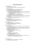
G2XPro with Display Dash and 620-KT-STBB Package
Dash Cable 36”
Vnet Terminator Cap
Vnet “T”
UDX Display Dash
Note: Mini dash equipped with
72” cable and “T’ connector.
Only need to install Terminator
cap
Vnet Cable 72”
Vnet Terminator Cap
Vnet “T” – 9”
G2X Pro
16
G2X Pro Installation Manual
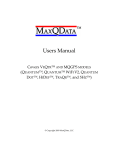
G2XPro with Display Dash and 620-KT-STBB Package
Steering, Throttle, Brake 1, Brake 2 Module
Vnet 4 Channel High Res Module
Dash Cable 36”
Vnet Terminator Cap
Vnet “T”
UDX Display Dash
Note: Mini dash equipped with
72” cable and “T’ connector.
Only need to install Terminator
cap
Vnet Cable 72”
Vnet Terminator Cap
Vnet “T” – 9”
G2X Pro
17
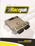
G2XPro with UDX Display Dash, 620-KT-STBB, 620-KT-4SHOCK and 620-KT-RIDEHT Packages
Steering, Throttle, Brake 1, Brake 2 Module
Front: Two Shock, Two Ride Height Module
Vnet 4 Channel High Res Module
Dash Cable 36”
Vnet Terminator Cap
Vnet “T”
IM Cable 72”
UDX Display Dash
Note: Mini dash equipped with
72” cable and “T’ connector.
Only need to install Terminator
cap
Vnet Cable 72”
Vnet Terminator Cap
Vnet “T” – 9”
IM Cable 48”
G2X Pro
Rear: Two Shock, Two Ride Height Module
18
G2X Pro Installation Manual
Adding Additional Vnet Sensors
When adding additional Vnet sensors to the previous sensor packages, Vnet Modules or
extension cable may simply connect to the 9” Vnet “T” connector located on the G2X Pro data
logger or at the firewall location of 4 Channel High Resolution Vnet module. The Vnet
Terminator caps are removed, the extension cables and modules connected and the terminator
caps reinstalled at the end of the new Vnet modules.
Add additional Vnet cables
and sensors starting here.
Vnet Cable 72”
Vnet Terminator Cap
Vnet “T” – 9”
Vnet Cable 84”
Vnet Terminator Cap
Vnet “T” – 9”
Add additional Vnet cables
and sensors starting here.
G2X Pro
Note: A Vnet Bulkhead connector PN: 280-CA-VMBHEAD should be utilized when passing
Vnet extension cables through any firewall location.
19
Engine RPM and Power Input
The G2X Pro acquires power, ground and engine RPM via the Power / Engine RPM cable. This
cable connects to the 1-4 RPM input of the data logger and provides a user terminated method of
acquiring this information.
Power / Engine RPM Cable
The three wire pigtail provides input for data logger power, ground and engine RPM.
The engine RPM input is a 5-18 Volt, 50% duty cycle square wave type. The three wire pigtail is
connected to the data logger by means of the Power-Engine RPM cable. This cable is unterminated, and supplied with a three pin Molex connector and protective shrink tubing.
To install the three pin Molex connector on the Power / Engine RPM cable:
1. Determine the distance from the data logger to the power/ground /engine RPM location.
2. Strip approximately 1” of the outer cable shield. Avoid cutting the wires contained inside
the cable.
3. Strip approximately .250 of wire shield from the red, black and clear wire
4. Trim the fourth wire (bare) out of the way
5. Place one of the female pins over one of the stripped wires. The exposed portion of the
wire should be positioned to allow the second set of crimp tabs to contain the exposed
wire, while a portion of the plastic wire shield should be placed to allow the first set of
crimp tabs to contain the plastic shield.
6. Crimp each set of tabs over the corresponding section of wire.
7. Repeat the process for all three wires.
8. Slide both pieces of shrink tube over the three crimped wires and allow each to slide
down the cable. Each female connector is designed to snap into the plastic Molex
housing
9. To snap each connector into place, simple locate the oval end of the plastic
Red
connector, gentle push each connector into the housing, until a snap is felt
Clear
and heard, according to the drawing shown to the right.
Black
10. Slide the small diameter shrink tube over the three exposed wires, apply
heat until appropriately shrunken. Slide the large diameter shrink tube
Molex
over the end of the plastic Molex housing and repeat the heat and shrink
process.
Following the above procedures, connect the three wire pigtail to the Power/Engine RPM cable
by means of the three pin Molex connectors. The three wire pigtail should be connected to the
power, ground and engine RPM of the vehicle, as shown below
Power (red)
RPM (yellow)
Ground (black)
20
G2X Pro Installation Manual
Mounting Location of Logger
The data logger is designed to be utilized in a race vehicle environment. However, there are
external conditions that can influence the operation and longevity of the system. Typically, the
logger should be mounted within the driver cockpit, as this provides the best protection along
with easy access. In addition:
Heat
Avoid excessive heat, such as generated from exhaust systems, transmissions, etc. If the exhaust
is routed under the floorboards, do not mount the logger on the floor pan. Best performance is
usually obtained when the logger is isolated from heat by mounting on a roll bar.
Electrical Interference
Avoid electrical interference. Race vehicle generate electrical interference from a variety of
locations such as ignitions, alternators, ECU, spark plugs, coils and radio/telemetry antennas.
This interference can affect the data generated by any or all of the sensors.
Moisture
Avoid excessive moisture. The logger is designed to be water resistant but not waterproof. Any
liquid on the logger will eventually find its way inside. Shield the logger from direct moisture.
If washing the vehicle, first cover before washing. Wipe any remaining moisture off of the
logger, when finished.
Easy Access
Do not mount the logger in a location that makes it difficult to access the memory card or any
connectors. Like any other racing related component, it will sometimes be necessary to access
the data logger, so try to avoid “hiding” the logger.
Movement
It is important to insure the data logger does not move during testing or can become dislodged
during an off track excursion.
21
Mounting Orientation of Logger
The logger contains inline and lateral accelerometers that perform two functions. First is for
graphical analysis of G data. The second is to work in conjunction with the GPS data to provide
trackmapping information. The logger must be mounted in the direction shown below.
Direction of travel
The logger should also be mounted as level as possible both left, right and front, rear.
Mounting Method
Four (4) rubber isolation feet are provided with the logger and should be used.
Billet mounting brackets are available from Racepak. These brackets are designed to clamp
around a section of roll cage tubing, providing a secure mounting platform.
Racepak Part Number
800-MB-V500-125
800-MB-V500-162
800-MB-V500-175
Outside Diameter of Attachment Tube
1.250”
1.625”
1.750”
If the logger is mounted in any other manner, insure:
1. The logger is securely mounted, using all four mounting holes
2. The logger is oriented correctly
3. The logger avoids heat, moisture and electrical interference
4. The logger can be easily accessed
22
G2X Pro Installation Manual
Power Supply and Grounding
The logger should be connected to a battery source that can supply a constant 10-16 volts. In
vehicles that utilize a master power switch, it recommended to connect the logger to the master
power switch. This not only insures the logger will be powered when the vehicle is in use, it also
insures power will be disconnected in the event of an emergency.
A good ground is very important to the function of the logger. Insure there is no type of paint,
rust or any other type of material that could prevent proper grounding. Boats often present
unique grounding problems. If necessary, provide an isolated power and ground for the G2XPro
as faulty grounds will create corrupt data.
Warning: Do not attempt to connect or disconnect any logger item, with the power
switched on. This action could result in damage to the data system.
Engine RPM Signal
Requirements: 5-18V, 50% duty cycle, square wave output. This signal is typically obtained
from the tach signal output of an aftermarket ignition box. Racepak also offers a GMR Inductive
RPM Pickup (Racepak PN: 680-SN-GMR) which is attached to the +12V coil power on coilpak,
coil on plug or points style ignition systems.
Warning: Do not connect the tach input wire directly to any part of the ignition coil. Doing
so will result in damage to the logger.
SD Memory Card Installation
The memory card is designed to utilize the molded card holder. This holder enables the user to
securely lock the memory card in place, along with providing a water resistant seal. The card
should be inserted into the data logger with the label up, facing the top of the logger. If
necessary, the card can be slid from the molded card holder, as it is held in place with double
side tape. This is sometimes necessary when placing the memory card in certain memory card
readers.
23
GPS Antenna Mounting
The GPS antenna is a moisture resistant, magnetic based type, designed to be mounted on the
exterior roof of the vehicle. If no roof exists or the vehicle is of a composite type, insure the
antenna is mounted in clear view of the sky, with no obstructions. The antenna must be mounted
at the highest point of the vehicle and level front / rear and left / right. Insure the GPS antenna
cable will reach the data logger, before final mounting of the antenna.
GPS antenna mounting for stock bodied vehicles
The GPS antenna is provided with a magnetic mounting base and should always be mounted on
the roof of the vehicle, centered within the roof area. Insure the antenna is as level as possible,
left to right and front to rear. In the event of a vehicle with a composite roof, Velcro can be
utilized. Place a strip of masking tape on the roof of the vehicle. A small piece of Velcro on the
antenna and the tape will be sufficient to hold the antenna in place. We understand the value of
high performance vehicles and the fact some users will be hesitant to place any type of tape on
the surface of their vehicle. In that is the situation, determine the mounting method you are most
comfortable with, but will locate the antenna on the roof area.
GPS antenna mounting for open wheel vehicles
By following the above instructions, simply insure the antenna is mounted as high as possible on
the vehicle. Various body panels can possible block satellite signals. Insure telemetry or two
way radio antennas will not provide interference to the antenna.
Again, the GPS antenna will function well, in a variety of roof mounted locations. The above
guidelines will insure the most efficient reception of signals. The antenna has been roof mounted
and tested at speeds over 190 mph, so feel free to go at least that fast.
Connection of the GPS antenna to the G2X
Upon completion of mounting of the antenna, simply route the cable to the data logger and
connect to the gps antenna port of the data logger. Insure the cable end is screwed tightly to the
GPS connector. A small wrench can be used to slightly SNUG the connector. Excessive force
can damage the connector, resulting in failure of GPS signal reception.
24
G2X Pro Installation Manual
GPS LED Display
While the number of located and locked GPS satellites is provided by the G2X Pro small display
dash, the data logger can also provide this information through a series of Red and Green LED
flashes. In order for the data logger to start logging (when GPS MPH is utilized for logging start)
and provide mapping data, it is necessary for the internal GPS board to locate and lock on the
position of at least three GPS satellites, orbiting overhead.
Upon initial power up, the user will
observe a sequence of RED and
GREEN LED flashes. The following
explains the sequence.
LED Indicators
SHORT RED:
Each short red flash indicates the end of one search cycle and the start of the next.
SHORT GREEN:
The green LED will short flash once for each located GPS satellite.
LONG GREEN:
The green LED will long flash once for each located GPS satellite.
Example:
One red flash followed by three long green flashes indicates three GPS satellites locked and in use.
Upon the first power-up of the day, the logger will take less than one minute to locate and lock
three satellites positions. If the power to the logger is removed or the vehicle is parked in a
covered area (garage) it will typically only take a matter of seconds for the logger to reacquire
satellites.
25
System Installation Order
As a general rule, the recommended order for a data system installation is as follows:
1.
2.
3.
4.
5.
6.
7.
8.
Mount the data logger
Mount the dash (if so equipped)
Mount all under-hood items (front shock sensors / steering / throttle / brake / etc)
Mount all rear end items (wheel rpm / rear shock sensors / etc)
Connect all under-hood items with appropriate cables (Vnet / Interface)
Connect all rear items with appropriate cables (Vnet / Interface / Digital Harness)
Connect all driver area items (engine rpm / power / dash /etc)
Route front / rear cables to the data logger and connect to appropriate ports on logger.
Maintaining a set procedure for the system installation will simplify the process, as each area of
the car is divided into sections (front / rear / drivers compartment) which should help reduce the
overall complexity of the system.
26
G2X Pro Installation Manual
Datalink II Software Installation
Data Download Path
The key to using the G2X Pro to improve performance is to understand the relationship between
the downloaded data, the G2X Pro Configuration file and the DatalinkII software.
Runfile
with lap data
Downloaded
Data
Configuration
File
Datalink II
Software
Downloaded Data: Stored G2X Pro data is downloaded to the users PC by means of the SD
memory card. Before the data can be opened into the Datalink II software, it must first pass
“through” the Configuration file.
Configuration File: The Configuration file contains all the information necessary to convert the
raw data saved on the memory card into a format that allows the file to be opened in the Datalink
II software. Channel names, scaling and calibrations values are assigned to each individual
sensor channel. In addition, the setup values for the data logger are saved in the Configuration
file. Each data logger arrives with a Configuration file created specifically for that system. The
Configuration file is a “template” for incoming data. All reports, vehicle information and etc that
is contained or entered in the Configuration file is transferred to the runfile during the download
process.
DatalinkII Software: The Datalink II software provides the ability to open and graph data
contained in a runfile. This software is generic in nature, in that it does not store information
related to the data logger setup. Instead, the software contains settings relevant to the graphing of
data and the users PC setup.
27
Computer Requirements
PC Hardware Requirements
· USB Port
· Serial Communications Port or USB Serial Port Adapter
· CD/DVD drive
· 3-1/2 inch Floppy Disk Drive
· 3 Button Mouse
Note: The use of a mouse with a center button is highly recommended
If your PC does not have a CD or floppy disk drive please contact RacePak and request the
optional DataLink II USB Flash Drive Installation Kit. This kit allows the DataLink II software
and license disk to be installed directly through the computers USB port. The DataLink II
software does not require a CD or Floppy Disk Drive for normal operation.
Screen Resolution
The DataLink II software requires a minimum screen resolution of 1024 x 768. We recommend
the use of the largest and highest resolution monitor that meets your installation and budget
requirements. The DataLink II program can present the user with large amounts of data; the
larger screen sizes and the higher resolution enhance the presentation capabilities. If your PC is
configured with dual monitor support, the DataLink II software has special features to take
advantage of the capabilities. An installation using dual flat panel (1280 x 1024 resolution)
narrow outline monitor such as those manufactured by Dell and Fujitsu is optimum for high-end
applications.
PC Software Requirements
The DataLink II software is compatible with Windows 98 Second Edition, ME, 2000, and XP
operating systems. If you have a Windows operating system other than those listed above please
contact RacePak for additional installation assistance. The DataLink II software is also
compatible with most PC’s designed for standalone operation currently being manufactured.
There are practical limits below which the software will not operate satisfactory. The minimum
PC requirements for the DataLink II software are as follows.
·
·
·
·
·
·
·
·
·
IBM PC or clone with 400 MHz Pentium Processor and 32 Mbytes Ram
Windows 98/ME/2000/XP Operating System
200 Mbytes free disk space
3.5 inch 1.4 Mbytes floppy disk drive
CD-ROM drive
Video card and monitor with a minimum resolution of 1024 x 768 pixels
Keyboard and 3 button mouse
Serial Communication Port or USB Serial Port Adapter
USB port if uploading data with a data cartridge and USB cartridge reader
28
G2X Pro Installation Manual
Software Installation
NOTE: Before installation, remove any DataLink or DataLink II software that was installed for
purposes of reviewing G2X Pro demo data. Removal should be performed utilizing the Uninstall
feature of Windows. We also recommend renaming or deleting the C:\RacePakData\ folder
installed by the original software. Some of these files cannot be deleted automatically and may
interfere with the operation of the G2X Pro.
To install the DataLink II software on your PC, perform the following.
1. Turn on the computer and start Windows.
2. Insert the CD labeled RacePak DataLink II Software into the CD drive.
3. The RacePak DataLink II Setup program will automatically start, and the setup
InstallShield Wizard will be displayed. Please note—If you have disabled auto run in
your computer the installation wizard will not automatically start.
4. To manually start the installation program; Select My Computer from the computer
desk top, select the CD drive by clicking on it and double click on Setup to start the
installation program.
5. Read the instructions on the dialog boxes and answer any questions required.
We recommend you install the software in the default directories as indicated during the
installation procedure. This will make it easier for our technicians to assist you at a later date
should you have an application problem. If you install the software in a directory other than the
default directory, please note the install directory, in order to assist our technicians should a
problem arise.
The Install Wizard will automatically create a shortcut on
RacePak DataLink II program.
29
the main desktop for the
License Disk Installation
Each data logger contains a serial number unique to that logger. Each G2X Pro data system is
shipped with a license disk created specifically for that system. The license disk contains a
Configuration (setup) file created specifically for the logger along with a unique set of security
numbers necessary to allow the user to open and review run data. These security numbers
prevents the transfer of data to another PC, unless the owner provides the security numbers.
To install the license disk information, open the RacePak DataLink II program by clicking on the
DatalinkII program icon. If this is the first time you have opened the DataLink II software, the
following dialog box will be displayed.
Next, following the below instructions:
1. Insert the license disk into the floppy drive or USB drive, type the correct drive letter in the
dialog box and select OK.
2. The program will install the contents of the license disk.
3. If you are installing the software from the optional USB Flash Drive, insert the USB
Flash Drive into the computers USB port and enter the drive letter for the USB Flash
Drive.
4. Next select OK. The DataLink II software will copy the information from the
license disk to your PC. This information copied includes the license keys required
to operate the DataLink II software, the base Configuration file created by RacePak
for your data logger, initial default settings for your application and updates to the
DataLink II software.
SD Flash Card Reader Installation
Data recorded by the data logger is stored on a standard SD memory card. In order to transfer
the data to the users PC, it is necessary to utilize a SD memory card reader. Many modern PC’s
have built-in readers. If your PC does not have a reader, you will need to purchase and install a
SD memory card reader, which are available at most electronics stores for a minimal cost.
Carefully follow the installation instructions provide by the card reader manufacturer.
30
G2X Pro Installation Manual
DataLink II Help Files
The DataLink II software includes extensive context sensitive help to guide the user through the
operation of the program. The help can be accessed by several methods. These are as follows:
1. To get help for any of the menu items simply highlight the menu item by placing the
mouse cursor over the menu item. Next press the F1 key to display the help.
2. To get help on the currently displayed dialog box press the F1 Key.
3. To get help on a tool bar item click on the
toolbar button located at the bottom of
the toolbar. The mouse cursor will change to a? Position the mouse cursor over toolbar
icon for which help is desired and click the left mouse cursor. Help on the icon will be
displayed.
4. To get help on the three sections of the DataLink II program screen click on the
toolbar button located at the bottom of the toolbar. The mouse cursor will change to a?
Position the mouse cursor over the section of the DataLink II screen for which help is
desired and click the mouse button. The help dialog box will be displayed. The three
help dialog boxes corresponding to the three data link screen are very useful as a quick
start into using the DataLink II program.
5. To get help on a run log page look for the blue icon with a question mark
click on the button to display the help for the run log page.
. Simply
6. Click on the Help main menu selection and select the Help Topics menu selection. The
Help Topics: DataLink II Applications Help will be displayed. Follow the instructions
included with the help box to navigate thru the online help
Demo Run Data File
The next step in getting familiar with the DataLink II program is to view and manipulate an
existing run data file. The demo run data file G2X_Demo.rpk was copied onto your PC during
the installation process. Appendix I include detailed instructions on opening the demo file while
providing a quick training session on using the DataLink II program to view run data files. We
strongly recommend that you go to Appendix I at this time and work your way through the demo
process before initial use of the data system. While this demo data was taken from a G2X data
logger, the procedures for graphing and reviewing data are the same for any of our systems.
It is much easier to learn how to graph and review data in the comfort of your home as opposed
to attempting to learn “on the fly” during a 110 degree day at the race track.
31
Serial Com Port Settings
In order for the users PC to communicate with the data logger for installation verification, it is
necessary to match the com port setting of the serial port to the com port setting of the Datalink
II software.
Open the DataLink II program. The connection to your PC is made through the 9 pin serial port,
located on the rear of the PC. Modern computers offer multiple connecting ports, which are
numbered COM 1, COM 2, etc. Most often, the serial port is considered COM 1. In order for
your PC to communicate with the data logger, we will now set COM 1 as the correct port
number.
To select COM 1 port for use, select the
Preferences menu item located in the
Settings main menu selection.
When selected the Edit Preferences dialog box will be
displayed as shown below. Locate the section on the
dialog box labeled Logger COM Port. Select COM 1
from the list to be used by clicking on the name of the
port.
If you are unable to determine the com port setting of
your serial port, refer to the following instructions or if
your PC does not have a serial communications port
and you are using a USB to serial port adapter you will
need to refer to following instructions.
32
G2X Pro Installation Manual
USB to Serial Adapter COM Port Number Setting
If you are utilizing a USB to serial port adapter, insure the adapter is correctly installed by
following the manufacturer’s instructions. Following the correct installation of the adapter, it will
then be necessary to determine the com port number of the USB port used by the adapter by
following these steps:
1. Minimize the Datalink II program and select the Start button located in the bottom left
area of your computer display
2. Select the Control Panel icon located in the small window.
3. Select System in the small window.
4. Select the Hardware tab located in the just opened Systems Properties window.
5. Select the Device Manager button located in the center/right of the Hardware page.
6. Locate the Ports (COM & LPT) in the currently opened list and double left click.
7. You will now see Communications Port (COM 1) or the appropriate com number for
your system
8. If you disconnect and re-connect the USB adapter, you will see the com port number
momentarily disappear, then re-appear thus verifying the com number.
Note the com port number, return to the Datalink II program and set the appropriate number in
the software, following the previous instructions.
The above instructions may be followed to verify any com port number, such as needed in the
previous Serial Com Port Setting.
33
Configuration File
The design of a Racepak data system is such that the DatalinkII software, in general, contains
little information or commands related to the programming of the data logger. This allows the
software to be generic to any form of motorsports. It is the Configuration file, however, that
contains all setup and programming features created specific to the data logger and the
motorsports in which it will be used.
The role of a config file is vitally important. When a system is ordered, Racepak personnel
design a config file specifically for that system. This file is linked to the data logger by means of
a serial number that is registered to the purchaser of the Racepak data system. The data loggers’
ability to both gather and download data is controlled by the config file.
Next, open the config file created for your system. To do so, select File
and Open Car Configuration from the Main menu screen.
This action will open a small dialog
window that lists all config files loaded with your system. By
default, generic config files are loaded by the software. The
config file will be identified by the serial number that
matches your data logger, for example, G2XPro_1234. The
left column lists all folders containing config files, while the
right column indicates the actual config file. Select the folder
from the left column that matches your data logger serial number. Following this action, the
system will display the config file contained within the folder, on the right. Select OK and the
config file will open within the DataLink II software.
A config file is identified by the Blue wrench icon. All sensors
shipped with the system should be represented by a Channel
Button. Each button provides access to all functions of that
channel. Typically, your data system will not require any update or
changes, as Racepak personnel have set up the Configuration file,
assembled and bench tested the system before shipping.
For example, to view all the logging parameters of Engine RPM
simply place the mouse cursor over the Engine RPM Channel Button
and right click. By doing so, the VNET Input Channel Parameters
dialog box will open and appear as shown at right.
Take time to review all the various items contained within this dialog box. All logging aspects
of this channel are accessed through this location. Scaling values, calibration values, channel ID,
smoothing and graphed result units, along with other parameters are available to the user. To
close the dialog box, simply select Cancel.
34
G2X Pro Installation Manual
Motorsports Specific Configuration Files
Racepak personnel have created a variety of Configuration files that are customized according to
the motorsports in which the data system will be utilized. Detailed information concerning each
Configuration file can be found in the Runlog and Configuration File Details section of this
manual.
Circletrack and Road Racing: This Configuration file contains a combination of Runlog pages
and math channels, created specifically for motorsports that require track mapping, lap and
segment information. In addition, math channels utilizing shock travel data are included
Boating: This Configuration file contains Runlog and math channel data specific to the needs of
boat motorsports that require track mapping, lap and segment information.
Pulling: This Configuration file contains Runlog pages specific to the sport of pulling, which
provides customers the ability to input pull specific information, within each run file.
Standard: Motorsports that can benefit from the use of GPS data, but do not fall under the above
categories can utilize our standard G2X Pro Configuration file.
35
Setting a Default Configuration
As you use your data system you may need to modify the setup of the data logger system or enter
new setup information for your vehicle. These changes are made via the Configuration file. To
simplify making these changes, the Configuration file is opened each time the Datalink II
program is run.
Multiple Configuration files may be created for single or multiple vehicles sharing the same data
logger. This allows the ability to add or remove sensors depending upon the testing or race
purpose, create and save individual Configuration files for each setup, then recall that particular
Configuration for use when needed. Each time data is downloaded, the system will prompt the
user to select the appropriate Configuration file. To shortcut this process, it is possible to set a
default Configuration that will automatically be chosen by the software, upon downloading of
data.
1. Open the DatalinkII software and Select File from the main menu area
2. Select Open Car Configuration from the pull down menu. A Select Configuration
dialog window will open. A list of folders containing Configuration files will appear
on the left side, while the actual Configuration files appear on the right side.
3. Select the G2X Pro folder on the left and the desired config file on the right.
4. Select File from the main menu area, and then click Default Configuration. A check
mark will appear before the Default Configuration menu.
At this point, the system should be installed in the vehicle, all sensors are connected and
calibrated and the software installed in the users PC. It is very important to become familiar with
the software, before performing the first test. The racetrack is not the best location to learn to
utilize the data system. While everyone will have software and hardware questions, the test
procedure will run more efficiently with a small amount of pre-test study procedures.
36
G2X Pro Installation Manual
Modifying the Data Logger Setup
As was discussed, the Configuration file contains the setup of your data logger, dash display and
data analysis screens as well as information entered by the user concerning track, weather and
car setup data. Each time new data is uploaded from your data logger the information contained
in the Configuration file is copied into the newly created run data file along with the data
recorded. The run data file then becomes a permanent record as to the setup of your data logger,
vehicle, and weather conditions at the time of the run as well as containing the actual run data.
The Configuration file is contained both in the users PC and the G2X Pro data logger. Any time
you make a change to either the Configuration file within your PC (for example a scaling change
to an individual channel) or a change to the data logger (add a new sensor) it is necessary to
update both the users PC and the data logger. The two situations in which it is necessary to
update the Configuration file are:
PC Configuration Changes
Write or Send to the data logger
Any changes made with the Configuration file in the users PC needs to be “sent” back to the data
logger, in order to update the logger memory.
Data Logger Configuration Changes
Read the data logger Configuration
Any change made to the data logger needs to be “read” by the users PC, in order to update the
Configuration file contained within the PC.
To get the most of your new system, you will want to keep the Configuration file up to date by
editing and saving the setup information in the Configuration file prior to loading new data from
the data logger. If you forget, the information can also be edited directly in the run data file.
You will also need to edit the information in the Configuration file if you wish it to be copied
into the next new run data file.
In most cases the factory default setup of the data logger system will meet your testing needs. In
certain applications for special testing you may need to modify the setup of the data logger In
these cases the DataLink II software and the Configuration file is used to perform the
modifications.
In order to make these modifications to the data logger you will need to perform the following
steps:
1. Read in the existing Configuration from your data logger system.
2. Modify and save the Configuration file to meet your new requirements
3. Write the Configuration to your data logger system.
4. Power the data logger off and back on to accept changes.
These steps are accomplished as follows:
37
Adding or Removing Sensors - Reading the Configuration
Following any modifications to the data logger (adding or removing sensors) it is necessary to
read the Configuration of the data logger back to the users PC. To perform this step you will
need to connect the Racepak serial communication cable between your PC and the Serial input
connector on the data logger, then power up the data logger. Next:
Select Edit, then Read VNet Config located in the main menu selection. When selected a
Message Log dialog box will be displayed and the read Configuration process will be started. As
the information is read in a log of the status will be displayed on the Message Log dialog box.
When completed the following Message Log dialog box will be appear as shown below.
The message Devices Read Successfully should appear at the bottom of the dialog box indicating
the read was successful. Select OK at this time.
38
G2X Pro Installation Manual
Modifying the Configuration File
After you have updated your Configuration file from the data logger, the next step is to edit the
Configuration file to meet your new requirements. You will notice a series of channel buttons at
the top of the data link screen when the Configuration file is open.
Each one of these channel buttons controls one of the aspects of the data logger system. For
instance the G2XPro_Module channel button is used to set the options such as record start
channel and record threshold used to control the main data logger system or the G2X_Dash
channel button is used to set the dash display parameters.
To select one of the features to be edited, position the mouse cursor over the desired channel
button and click the Right mouse button. An easy edit dialog box for that channel button will be
opened. As an example position the mouse cursor over the G2X_Dash channel button and click
the Right mouse button.
In the upper left corner of the dialog box is the instruction box “G2X Display Dash Setup
Instructions”. The box contains the instructions for setting the various parameters on the G2X
dash via the easy edit dialog box.
A similar dialog box will be displayed for each of the channel buttons contained in the
Configuration file. Although the boxes will be different each will contain the setup instructions
in the upper left hand corner. Follow the setup instructions and make the desired modification.
After you have made your modifications select the OK button to accept the changes.
Repeat the above process until all of the modifications have been made. Next select the “Save”
icon in the toolbar or select the Save option located in the File main menu selection to save your
changes to disk.
39
Writing or Send the Configuration
Following any changes, the final step is to write the Configuration file to your data logger. Be
sure the serial cable is still connected between the data logger and your PC and the power is
connected to the data logger.
Next select the Write VNet Config menu item located in the Edit main menu selection. The
Message Log dialog box will be displayed and status messages will scroll on the box as the
Configuration is updated. When the write operation is complete the message Devices
Programmed Successfully will be displayed on the bottom of the Message Log dialog box as
shown below.
Your data logger has now been programmed with the new changes. Before the data logger can be
used the serial cable must be removed from the data logger and power to the data logger must
turned off and back on.
40
G2X Pro Installation Manual
Configuration File Details
Circletrack and Road Racing Configuration File
At this time, the system installation should be complete. Next, we would like to review the
custom information contained in each Configuration file, specific to the type of motorsports.
Insure the Configuration file is open in the Datalink II software.
Factory Defined Shock and Ride Height Channels: This Configuration file arrives from the
factory with four shock and four ride height channels defined. However, they are not active until
enabled by the user. Instructions concerning these channels are provided with each sensor
package.
Factory Defined Math Channels: Racepak personnel have installed a set of math channels that
provide data specific to suspension and chassis analysis. These channels are dependant upon the
input of four shock sensors. If the system does not utilize a shock sensor package, data will not
be valid.
Shock Velocity
Channel name: LF Shk_Velocity / RF Shk_Velocity / LR Shk_Velocity / RR Shk_Velocity
The above channels provide shock velocity. The data is derived from the shock travel channel
multiplied by the derivative.
Ride
Channel name: Ride_Front / Ride_Rear
The above channels provide the front / rear attitude of the vehicle. Positive data indicates pitch
down and negative data indicates pitch up.
Pitch
Channel name: Pitch_Total
The above channel provides average pitch of the vehicle in inches, front to rear. Positive data
indicates a nose down attitude, while negative data indicates a tail down attitude.
Roll
Channel name: Roll_Front / Roll_Rear / Roll_Total
The above data represents the roll of the vehicle, in inches. Positive data indicates a roll to the
right, while negative data indicates a roll to the left.
41
Pre-Defined Difference Channel:
There are four delta or difference channels provided in this Configuration file. This provides the
ability to graphically compare the difference between two channel values. The resulting graph
provides a straight graph line for the Reference file, with the Main file showing the difference
between the two channels in graphical format.
LapT_Difference
Compares the difference between lap times from two selected Runfiles.
LatG_Difference
Compares the difference between lateral g data from two selected Runfiles.
AccG_Difference
Compares the difference between accel g data from two selected Runfiles.
MPH_Difference
Compares the difference between speeds from two selected Runfiles.
To activate the above channels:
1.
2.
3.
4.
Review the Main and Reference instructions in the following section, first
Select the desired Main and Reference file
Graph the desired difference channel in the Main and Reference file
Place the data in distance mode by select View, then Segment X Mode
At this time, the graphed data should be in view, ready for analysis. It is recommended to review
only one difference channel at a time, to simplify the review process.
The DataLink II software provides the user the ability to create a multitude of math channels,
utilizing the Edit / Channel Maintenance command, found in the main menu selection.
42
G2X Pro Installation Manual
Circletrack and Road Racing Runlog Pages
Racepak personnel have created a selection of pre-configured Runlog pages that are considered
standard, for circle track and road race motorsports. To select any Runlog page, simply left click
over the MENU Runlog tab. This will access the 8 categories of pre-configured Runlog pages.
Left click over any category, to access individual pages.
All Runlog pages are copied into each new run, providing the user an opportunity to insert data
relative to each run. Data inserted remains with each run for current or later data analysis
Session Info and Weather
1. Session
2. Weather
3. Run Comments
Provides an input area for run numbering data, weather conditions and comments. Data is
inserted by the user, as needed
Map Setup
1. Create GPS Map
2. Add Map Segments
3. Add Inside - Outside Track (optional)
Provides an input area to create and segment track data. Additional information can be found in
the following section.
Map Analysis
1. Map Report
2. Lap Zoom
3. Segment Report
4. Segment Compare
5. Speed Compare
6. Min Max Avg Report
7. GG Plot
Provides an input area to review and analyze data. Additional information can be found in the
following section.
43
Histograms
1. Steering Throttle Brake1 Brake2
2. Shock Travel
3. Shock Velocity
4. RPM and MPH
5. Ride
6. Roll
7. G’s
The above set of histograms represents the most commonly utilized. In order to activate the
histograms, the user must place average cursors within the Main Graph area. To place the
cursors:
1. Move the mouse cursor within the graph area, to the desire start of the averaging area.
2. Place a { (beside the P on the PC keyboard) in the graph area
3. Move the mouse cursor to the desired stop of the averaging area.
4. Place a } in the graph area.
The above action will activate the Minimum / Maximum / Average capabilities of the Datalink II
software. To view the histograms, simply select the appropriate page, and the histogram data will
be in view.
Real Time Displays
1. Dash
2. User Gauges
3. On Track Telemetry
Provides the ability to view data in an analog real-time format. Additional information can be
found in the following sections.
User Defined Runlog Pages
1. User Page 1
2. User Page 2
3. User Page 3
Provides the ability to create custom Runlog pages. Additional information can be found in the
following sections.
44
G2X Pro Installation Manual
Car Setup
1. Chassis Scaling
2. Tire Data
3. Setup Specs
Chassis Scaling Runlog
The function of chassis scales is contained within this Runlog page. By inputting the four corner
weights of a scaled vehicle, the Chassis Scaling page can calculate the following information:
1. Total Weight
2. Cross Weight
3. Cross Weight Percentage
4. Left Side Total Weight
5. Left Side Total Percentage
6. Right Side Total Weight
7. Right Side Total Percentage
8. Front Percentage
9. Rear Percentage
10. Total Left Side Lead
11. Total Right Side Lead
Again, this information may be entered into the Chassis Scaling Runlog page, prior to the start of
testing. This Runlog page can also be used to calculate the set up information, while at the shop.
Simply input the corner weights and the Runlog page automatically provides the above 11 items.
Tire Data
This Runlog page was designed to provide an area to input tire temperatures and pressure build
up, during track test events. However, the Tire Pressure Cold data should be entered before the
start of testing. Following a test run, if tire temp readings are obtained by means of a hand held
probe, the individual temperatures can be inserted into this Runlog page. By doing so, the
system can provide the following information:
1. Left Front Average 2. Right Front Average 3. Average Overall Front
4. Left Rear Average 5. Right Rear Average 6. Average Overall Rear
In addition, if the cold and hot tire pressure data is inserted, the system can provide the following
information: 1. Left Front / Right Front / Left Rear / Right Rear Pressure Gain
Setup Specs
This page provides a generic chassis setup input area. Any information entered will be saved
with each downloaded run, thus assuring relevant chassis data remains with each run. Again,
remember to enter this information the Configuration file and update accordingly throughout the
test or race session.
45
Exporting the Start / Finish Position Runlog Page
The G2X_Pro Config file used in Version 2.7b or higher of the DatalinkII software provides the
ability to export the start / finish location (as set in the GPS Trackmap) to the memory card.
When the card is re-inserted into the data logger, this start / finish location is automatically
installed in the data logger, thus eliminating the need to set the start / finish location with the
Display Dash.
To export the GPS Trackmap start / finish location to the data logger:
1. Insure a GPS trackmap has been created for the selected Runfile, following all four steps
found in the Create GPS Track Map Runlog page.
2. Remember to place the start / finish of the GPS trackmap in a location that will be both
familiar to the driver and in an area that laptime data will be easy to read when on the
track. Typically this will be on the front straight of most tracks, as that affords the driver
a bit of time to glance at the lap time and lap number.
3. Select the Runlog Menu tab found at the bottom of the DatalinkII software.
4. Locate the Write Start/Finish Position to Card button as found under the Favorite Log
Page Shortcuts area.
5. Connect the memory card to your PC via the method used when downloading data to the
users PC (typically a USB flash card reader).
6. Select the Write Start/Finish Position to Card button.
This action automatically places the GPS trackmap start / finish position on the memory card.
Following this action, simple insert the memory card into the data logger and apply power.
The start / finish is now set, which will allow the display dash to provide lap time and lap
number information. This start / finish location can be re-set by using the Display Dash method
or by exporting another start / finish location to the compact flash card (as taken from the GPS
trackmap).
WARNING: Do not make any changes to the start finish file that is saved to the memory card.
Editing the name or file type will result in failure to write the start / finish location to the data
logger.
IMPORTANT: This feature requires G2X Pro firmware version 36 or higher. Updated
firmware is available for free at www.g2xpro.com
46
G2X Pro Installation Manual
TrackVision Export Runlog Page
The G2X_Config file found in Version 2.7b or higher of the DatalinkII program allows the user
to quickly export data from the DatalinkII software for use in the TrackVision video software.
This is accomplished through the use of our TrackVision Export Runlog page. This page can be
accessed by selecting the Track Vision Export button found on the Runlog Menu page, under the
Favorite Log Page Shortcuts heading.
The TrackVision Export Runlog page enables the user to quickly export a list of standard
TrackVision related data channels. In addition, the user can also create a customized list of data
channels to be exported for use in the TrackVision software.
Exporting pre-defined TrackVision data channels:
1. Open a Runfile that was downloaded utilizing the updated G2X_Config file found in
Version 2.7b or higher of the DatalinkII software.
2. Select the Run Log Menu Runlog tab at the bottom of the DatalinkII software.
3. Select the Track Vision Export button found under the Favorite Log Page Shortcuts
heading as shown below.
The user is presented with two options:
1. Export Standard TrackVision Data
2. Export Custom TrackVision Data
Exporting Standard TrackVision Data:
1. Select the Export Standard Track Vision Data button.
2. Data is automatically exported to the following file folder location:
C:\RacePakData\TrackVision_Std.csv
3. Data is now saved and ready for use in the TrackVision software.
47
Boat Racing Configuration
Pre-Defined Math Channels: Racepak personnel have installed a set of math channels that
provide data specific to boat racing analysis.
Prop Speed
Channel name: Prop Speed
The Prop Speed channel is derived from the input of Engine RPM, Gear Ratio, Prop Pitch and
various internal mathematical functions. In order for this channel to provide accurate data, it is
necessary to manually insert all the information found in the Prop Data Runlog page.
Prop Slip
Channel name: Prop Slip
The Prop Slip channel is created from the input of GPS MPH and prop speed. Again, insure the
PROP DATA information is completed and the GPS data is functioning correctly.
48
G2X Pro Installation Manual
Pre-Defined Difference Channels
There are four delta or difference channels provided in this Configuration file. This provides the
ability to graphically compare the difference between two channel values. The resulting graph
provides a straight graph line for the Reference file, with the Main file showing the difference
between the two channels in graphical format.
LapT_Difference
Compares the difference between lap times from two selected Runfiles.
LatG_Difference
Compares the difference between lateral g data from two selected Runfiles.
AccG_Difference
Compares the difference between accel g data from two selected Runfiles.
MPH_Difference
Compares the difference between speeds from two selected Runfiles.
To activate the above channels:
5.
6.
7.
8.
Review the Main and Reference instructions in the following section, first
Select the desired Main and Reference file
Graph the desired difference channel in the Main and Reference file
Place the data in distance mode by select View, then Segment X Mode
At this time, the graphed data should be in view, ready for analysis. It is recommended to review
only one difference channel at a time, to simplify the review process.
The DataLink II software provides the user the ability to create a multitude of math channels,
utilizing the Edit / Channel Maintenance command, found in the main menu selection.
49
Boat Racing Runlog Pages
Racepak personnel have created a selection of pre-configured Runlog pages that are considered
standard for boat related motorsports. To select any Runlog page, simply left click over the
MENU Runlog tab. This will access the 6 categories of pre-configured Runlog pages. Left click
over any category, to access individual pages.
All Runlog page data is copied into each new run, providing the user an opportunity to insert
data relative to each run. Data inserted remains with each run for current or later data analysis.
Session Info and Weather
1. Session
2. Weather
3. Run Comments
Provides an input area for run numbering data, weather conditions and comments. Data is
inserted by the user, as needed
Map Setup
1. Create GPS Map
2. Add Map Segments
3. Add Inside - Outside Track (optional)
Provides an input area to create and segment track data. Additional information can be found in
the following section.
Map Analysis
1. Map Report
2. Lap Zoom
3. Segment Report
4. Segment Compare
5. Speed Compare
6. Min Max Avg Report
7. GG Plot
Provides an input area to review and analyze data. Additional information can be found in the
following section.
50
G2X Pro Installation Manual
Prop Data and Accel Reports
1. Prop Data
2. Accel Times
3. Accel Times Scroll
Prop Data
In order to activate the Prop Slip and Prop Speed data channels, it is necessary to complete the
gear and prop data information contained on the Prop Data Runlog page. This, in turn, activates
the mathematical functions of the Prop Slip and Prop Speed data channels, thus allowing
graphing of data. Insure this information is kept current in the Configuration file.
Accel Time and Accel Scroll Runlog Page
The Accel Time Runlog page provides acceleration time data, in report format. The Datalink II
software combines GPS MPH data with beginning and ending MPH points inserted by the user,
to calculate the time between two MPH points.
1. Open a Runfile and graph GPS_MPH
2. Open Accel Times Runlog page
3. Enter the desired speed to start the report and the desired display MPH increments, in the
input area located at the top of the Accel Times Runlog page. For example, if 50 MPH
is inserted as the Enter Speed and 10 is inserted in the Display Time Every area, the report
will start at 50 MPH and display data in 10 MPH increments.
4. Place the cursor in the Main Graph area, then locate the cursor at a starting point in the
acceleration data. Remember to locate the cursor at a point that is below the desire MPH for
the start of the report. For example, if the starting point of the report will be 50 MPH, the
marker placed in the data can not be located above 50 MPH. If the desired starting point for
the report will be 50 mph, locate the cursor at 40 MPH in the Main Graph area.
5. Locate the Add/Edit Segment Lap Markers icon, in the list of vertical icons
found on the left side of the Datalink II software.
6. Left click the icon, which will open the Edit / Add / Remove Section Markers dialog box.
7. Select the Insert New Lap Marker At Cursor Button
8. Left click the Lap Markers channel button, in order to display the
inserted lap marker within the Main Graph area.
8. Move the cursor to the desired ending point of the accel run, and repeat steps 6 and 7.
51
9. If multiple acceleration runs were made during the run, continue to place makers at desired
beginning and ending mph points.
10. Remember to only place markers within acceleration points within the graphed data. Do not
place the beginning marker at an acceleration point and a second maker at a slowing down
or deceleration point within the data.
11. The Datalink II software is designed to review acceleration data between two markers
and provide time data. If multiple markers are placed, the Datalink II software automatically
continues to create time data for each pair of markers, as seen in the example below.
To utilize the Accel Scroll Runlog page, simply place the mouse cursor over the slider
located at the top of the Accel Scroll Runlog page, right click and hold then drag the slider left or
right to move the accel data accordingly. This feature allows the user to view data that extends
out of view of the screen area.
52
G2X Pro Installation Manual
Real Time Displays
1. Dash
2. User Gauges
3. On Track Telemetry
Provides the ability to view data in an analog real-time format. Additional information can be
found in the following sections.
User Defined Runlog Pages
1. User Page 1
2. User Page 2
3. User Page 3
Provides the ability to create custom Runlog pages. Additional information can be found in the
following sections.
53
Exporting the Start / Finish Position Runlog Page
The G2X_Pro Config file used in Version 2.7b or higher of the DatalinkII software provides the
ability to export the start / finish location (as set in the GPS Trackmap) to the memory card.
When the card is re-inserted into the data logger, this start / finish location is automatically
installed in the data logger, thus eliminating the need to set the start / finish location with the
Display Dash.
To export the GPS Trackmap start / finish location to the data logger:
7. Insure a GPS trackmap has been created for the selected Runfile, following all four steps
found in the Create GPS Track Map Runlog page.
8. Remember to place the start / finish of the GPS trackmap in a location that will be both
familiar to the driver and in an area that laptime data will be easy to read when on the
track. Typically this will be on the front straight of most tracks, as that affords the driver
a bit of time to glance at the lap time and lap number.
9. Select the Runlog Menu tab found at the bottom of the DatalinkII software.
10. Locate the Write Start/Finish Position to Card button as found under the Favorite Log
Page Shortcuts area.
11. Connect the memory card to your PC via the method used when downloading data to the
users PC (typically a USB flash card reader).
12. Select the Write Start/Finish Position to Card button.
This action automatically places the GPS trackmap start / finish position on the memory card.
Following this action, simple insert the memory card into the data logger and apply power.
The start / finish is now set, which will allow the display dash to provide lap time and lap
number information. This start / finish location can be re-set by using the Display Dash method
or by exporting another start / finish location to the compact flash card (as taken from the GPS
trackmap).
WARNING: Do not make any changes to the start finish file that is saved to the memory card.
Editing the name or file type will result in failure to write the start / finish location to the data
logger.
IMPORTANT: This feature requires G2X Pro firmware version 36 or higher. Updated
firmware is available for free at www.g2xpro.com
54
G2X Pro Installation Manual
TrackVision Export Runlog Page
The G2X_Config file found in Version 2.7b or higher of the DatalinkII program allows the user
to quickly export data from the DatalinkII software for use in the TrackVision video software.
This is accomplished through the use of our TrackVision Export Runlog page. This page can be
accessed by selecting the Track Vision Export button found on the Runlog Menu page, under the
Favorite Log Page Shortcuts heading.
The TrackVision Export Runlog page enables the user to quickly export a list of standard
TrackVision related data channels. In addition, the user can also create a customized list of data
channels to be exported for use in the TrackVision software.
Exporting pre-defined TrackVision data channels:
4. Open a Runfile that was downloaded utilizing the updated G2X_Config file found in
Version 2.7b or higher of the DatalinkII software.
5. Select the Run Log Menu Runlog tab at the bottom of the DatalinkII software.
6. Select the Track Vision Export button found under the Favorite Log Page Shortcuts
heading as shown below.
The user is presented with two options:
3. Export Standard TrackVision Data
4. Export Custom TrackVision Data
Exporting Standard TrackVision Data:
4. Select the Export Standard Track Vision Data button.
5. Data is automatically exported to the following file folder location:
C:\RacePakData\TrackVision_Std.csv
6. Data is now saved and ready for use in the TrackVision software.
55
Puller Runlog Pages
Racepak personnel have created a selection of pre-configured Runlog pages that are considered
helpful for pullers. To select any Runlog page, simply left click over the Runlog tab.
All Runlog pages are copied into each new run, providing the user an opportunity to insert data
relative to each run. Data inserted remains with each run for current or later data analysis.
Session
Provides an input area for run numbering data, weather conditions and comments. Data is
inserted by the user, as needed.
Pull Info
Provides an area to input pulled related information.
Weather
Provides an area to input weather information.
Vehicle and Track Info
Provides an area to input vehicle setup and track condition information.
Dash Gauges
Allows the user to select the input channel to activate each gauge. Can be used during telemetry
or review of downloaded data.
User Defined Runlog Pages
1. User Page 1
2. User Page 2
Provides the ability to create custom Runlog pages. Additional information can be found in the
following sections.
56
G2X Pro Installation Manual
Making the Initial Run
Transferring Data
Following recording of data, drive the vehicle to a safe location in order to transfer and review
the data. The logger creates a new file and saves all data gathered from the start of logging
(speed greater than 25 MPH) to the end of logging (speed less than 25 MPH for 30 seconds).
Each file is saved in a .ddf format and is assigned a number based on date and time. Multiple
files can be saved to the memory card.
When a .ddf file is transferred to the DataLink II program, it is then assigned a file name based
on the track, date and run number. At that time, it becomes a Runfile. All of the lap data is
contained within the Runfile and is called a Lapfile. While it is not necessary to transfer your
data after each run, it is highly recommended, if at all possible.
Only one Run file can be transferred at a time, so you must perform the following procedure
once for each .ddf data file or recording.
1. If desired, dash lap time data can be reviewed before downloading.
2. Turn off power to the data logger.
3. Open the DataLink II program, and insert the memory card into the card reader.
4. Initiate the transfer sequence by selecting the New Upload icon.
5. The Select Configuration dialog window will open. Select the appropriate Configuration
file and OK.
6. The Open dialog window will open. The first time data is
uploaded you will need to select the drive letter
corresponding to the compact flash reader.
7. There will be one .ddf file for each recording. In this
example, there are multiple .ddf files. If multiple files are
listed, select the desired file to download and select Open.
8. The file will download and the Session dialog window will open.
57
Session Dialog Window
At this time, we will explain the purpose of the Session dialog window. When data is
downloaded to the users PC, a data path must be created. This provides a folder for the DataLink
II software to place each Runfile. At the same time, a number must be assigned to the Runfile
before the file can be placed into the designated folder. The Session page provides the ability to
assign both the run number and the location in which to save the Runfile.
The Year selection creates a folder according to the year entered. The Track selection creates a
folder according to the track name entered. For this reason, it is only necessary to enter the Year
one time, according to the year of testing. It is also only necessary to enter the Track name one
time, at each track.
An example data path: C\RacepakData\G2XPro\2005\Infineon
If 2005 was entered for the Year and Infineon for Track, the above set of folders (or directory)
would be created on the user’s C drive. The Runfile number is assigned according to the date,
location and run number.
1. Enter the appropriate information in the Session dialog box and select Next.
58
G2X Pro Installation Manual
Map Select Dialog Window
The Map Select Dialog Window is designed to assist the user in selecting previously created and
saved GPS Track Maps. After extended use of the data system, it is possible to have quite a
large collection of saved maps. However, the Racepak engineers have created a unique way to
provide a limited number of maps for selection. Upon download of a new run, the Datalink II
software reviews the location of the vehicle, relative to GPS data. Then, only previously saved
maps that are located within a five mile radius of the new uploaded run, will be displayed for
selection.
For a run at a new location that does not detect any previously saved track maps within that five
mile radius, the above Create New message will appear in the Map Select Dialog Window.
Since these instructions assume this is the first download for a new system:
1. Select Next
2. The Weather dialog box will be presented. If desired, enter the current weather
conditions. If not desired, this information can be entered at a later date, then select OK.
59
3. The final dialog window to be presented to the user is the Save window. This allows the
user to review the save location and Runfile number. If any changes are desired, they
made be performed at this time. If no changes are desired, select SAVE.
At this time, the Runfile is now open the DataLink II software. The next step is to create a GPS
track map. First, we will review the procedures that must be applied to a Runfile, when the G2X
Pro is utilized by pulling competitors. Creating trackmaps does not apply to our Pulling
customers.
60
G2X Pro Installation Manual
Puller Run - Setting the Zero Start Point - Very Important
In order for puller competitors to accurately review data, it is necessary to reset the start of
graphed data (Zero Point) for each run. When data is initially downloaded and graphed, the
starting point of the graphed data is when the data logger started saving data to the compact flash
card. For example, if the data logger is set to start logging when engine rpm exceeds 3000, that
point could occur while driving up to the sled, on the first pull. Suppose on the second pull, the
motor does not exceed 3000 rpm until the vehicle is starting the actual pull. When data is
downloaded and graphed, the zero time (or starting point) of the data will be at two totally
different locations. This makes it impossible to accurately overlay and graph data.
The solution to this situation is to manually move the zero time point to the same location, within
each run. This is accomplished by using the Set Start Time icon, located in the DatalinkII
software. To perform this procedure:
1. Open a Runfile
At this time, it will be necessary to determine what data channel will always be used to
determine the first movement of the vehicle. For pullers, the Accel G channel works well.
2. Graph the Accel G channel.
3. Select the Autoscale icon. This will display all data from beginning to end.
4. Place the cursor in the Main Graph area (the area with the colored graph line)
5. Press and hold down the left mouse button (starting at the very beginning of the run).
6. Drag the mouse to the right until the very first movement of the vehicle is noted.
7. The first movement of the vehicle will be obvious, with an upward spike in Accel G data.
Upward Spike
Determine the first movement of the vehicle by continuing to hold the left mouse button down
and watching the real time Accel G Channel Button data (at the top of the page). The Zero start
time will be when the Accel G Channel Button data begins to increase. When the start of the run
is located:
8. Select the Set Start Time icon
9. The Confirm Data Start Time Change
window will open. Select OK
At this time, the graphed data will now start at the new zero time as set by this action.
NOTE: It is vitally important to perform this procedure on every run, or accurate data overlay will not be possible.
Create Trackmap - Required for Closed Course / Oval & Road Race
61
G2X Pro Installation Manual
Create Trackmap (Closed Course) Oval and Road Racing
Upon download of the initial run, it is advisable to quickly check two channels, to verify system
operation. Two suggested channels are the GPS_MPH and GPS_Satellites. Typically, if those
two channels are correct, all the remaining GPS functions will be correct.
At this time, the initial run should be in view, in the DataLink II software. To graph the
GPS_MPH channel:
1. Place the mouse cursor over the GPS_MPH Channel Button and left click.
2. The GPS_MPH data should now be in view, in the Main Graph area.
3. Locate and left click the Autoscale icon,
located in the vertical icon list on the left
side of the screen. All graphed data, from the start of logging until the end of logging, will
be displayed.
4. Next, graph the GPS_Satellites channel by placing the mouse cursor over the GPS_Satellites
Channel Button and left clicking. This action will display the number of satellites utilized
during this particular run.
5. A minimum of three satellites are required at any given time in a run, in order to produce
valid data. Typically, the logger will utilize between three and seven satellites.
Your screen should appear as shown below:
G2X Pro Installation Manual
If no previously save trackmap exists for the newly downloaded data, the next action that must
be performed is the creation of a GPS track map. A GPS track map is the most important item
for data review, as the track map controls all of the timing functions of the logger and DataLink
II software. Without a GPS track map, no lap times, segment times or visual driving lines will be
available.
In essence, the creation of a GPS track map is the same as physically placing start / finish and
segment beacons at various points around the race course. The difference is we are re-creating
the track in the DataLink II software utilizing GPS information, then inserting (in the software)
the start / finish and segment timing points at various locations around the GPS track map.
Those timing points are also GPS plotted positions and provide timing information with the same
accuracy as trackside beacons.
GPS track map files are saved according to the name assigned by the user. Typically, the name
will reflect the name of the track or location in use. Saved GPS track map files can then be
recalled for use, according to the testing location and needs of the user. The procedures for
creating a GPS track map are quick, easy and listed in numerical order, Step 1 through Step 4.
At this time, our initial run data should still be in view. To create a GPS track map, select the
Map Setup Category button, then select the GPS Trackmap Runlog tab, located at the bottom of
the DataLink II screen. The instructions are presented in order from 1 through 4.
Step 1: Select / Create GPS Map
Left click over the Select / Create GPS Map. This opens a Select/Create GPS MAP dialog box.
The user is presented with three choices, which are self explanatory:
1. New (Clear) Lap File: This allows the creation of a new track map.
2. Open Different Lap File: This allows the user to load a
previously created track map.
3. Rename/Save Lap File: This allows the user to rename a
previously created track map or simply save an
existing track map.
For the initial run, we will select New Trackmap and then OK.
The Save As dialog box will now be opened for the user. Simply type
the desired track or location name (example: Road Atlanta)
then select the Save button.
Following this action, the user will be returned to the DataLink II software. The Create GPS
Trackmap Runlog page should now display all of the GPS driving data. Remember, at this point
the GPS data in view is all data logged from the start until the end of recording.
63
Step 2: Select Track Type
The next step is to assign the type of track in use for testing. Most all testing will be considered
the default setting of Closed Course. Open Course is typically used for events such as Autocross
and Hill Climbing, which is covered in the following section.
Step 3: SET LAP START
SET LAP END (Open Course Only
As discussed in the previous section, the current data in view represents the GPS position of the
vehicle from the start until the end of recording. If you were to place the mouse cursor in the
Main Graph area, (insure GPS_MPH is still graphed and the entire run is in view) then left click
and drag the mouse curser through the Main Graph area, you can follow the location of the
vehicle in the GPS driving line data. However, there will be no lap data, until a start / finish line
is assigned.
To Set Lap Start, place the mouse cursor in the Main Graph area,
left click and move the vehicle location (as noted by the small X) in
the GPS map data until the approximate start / finish is located.
Next, simply select the Set Lap Start button. Just consider this
action the same as physically placing a beacon transmitter on the
start / finish line of the race course, except this is much easier.
In order to generate a GPS track map, the final step will be to view a lap and create the map from
that actual lap.
Step 4: Create GPS Track Map
To view a lap, locate the LAP NUMBER widow shown under Step 4. By using the Up / Down
arrows, the user can toggle through all of the laps contained within the run. To select a lap,
simply choose a lap that represents a complete, high speed lap. This lap will also be utilized to
generate segment timing, so choosing a high speed lap with the greatest lateral g forces, will
assist in the segmentation.
Now, select the CREATE GPS TRACKMAP button. This action now completes the GPS
track mapping process.
As with many activities, the actual explanation of the track mapping procedure appears
extensive, while the actual process takes less than 30 seconds.
64
Vehicle
Location
G2X Pro Installation Manual
Track Map Creation (Open - Autocross, Solo & Hill Climb)
Through the use of GPS signals, it is possible to create a track map, even if the start and finish
line are located at two different locations. In the previous section, we located the vehicle at the
desired start / finish and selected the Set Lap Start button. For open course, we need to also
establish an end point of the lap, also. To create an open course track map, we will refer to the
previous section and follow the same instructions for Step 1. Resuming at Step 2:
Step 2: Select Track Type
For open course, select Open Course.
Step 3: Set Lap Start
Set Lap End (Open Course Only)
As discussed in the previous section, the current data in view represents the GPS position of the
vehicle from the start until the end of recording. If you were to place the mouse cursor in the
Main Graph area, (insure GPS_MPH is still graphed and the entire run is in view) then left click
and drag the mouse curser through the Main Graph area, you can follow the location of the
vehicle in the GPS driving line data.
To Set Lap Start, place the mouse cursor in the Main Graph area, left click and move the
vehicle location (as noted by the small X) in the GPS map data until the approximate start
area is located. Next, select the Set Lap Start button. Then, move the curser to the desire end of
the course and select the Set Lap End button.
Step 4: Create GPS Track Map
Finally, select the CREATE GPS TRACK MAP button. This action now completes the GPS
track mapping process.
65
Add Map Segments - Closed Course Tracks Only
Now that we have created a GPS track map, the next step is to create track segments. In order
for the DataLink II software to provide segment data, it is necessary to break the track into
corners. Each corner will represent the start and end of a timing segment. However, in this
instance, we will use Lateral G forces to create the segments for us. By doing so, it automates
the process and eliminates the necessity of manually assigning segments.
Open the Add Map Segments Runlog page. Next, graph the Lateral G channel. Review the data
and determine the approximate Lateral G value obtained upon entry to most of the corners.
Next, determine the approximate Lateral G value upon exiting most corners. At high speed, high
lateral g force tracks, it is recommended to attempt to maintain at least .5 G difference between
the maximum and minimum values. Following this:
Step 1: Open Lap
To generate segments, it is necessary to open a lap. Use the same lap as previously selected to
generate the track map.
Step 2: Generate Segments
1. Insert the desire maximum Lateral G value in the Corner Start input box
2. Insert the desired minimum Lateral G value in the Corner End input box
3. Select the Generate Segments button.
Following this action, the DataLink II software will segment the GPS track map, and assign
names to each corner. Often times, a road course will assign a variety of names, to the same
corner. For example, the DataLink II software will assign a Turn 7 and Turn 8 to the track map.
However, the “official” name for the turn could be shown as Turn 7a and Turn 7b and Turn 7c.
In this case, the user may insert a variety of Lateral G values to create the approximate correct
number of turns.
When creating circle track segments, the system will automatically create only two turns. In
order to divide the track into four corners, it will be necessary to manually edit the segments, as
reviewed in the following section
!!! IMPORTANT WARNING!!!
The default Corner Start and Corner End lateral g values that appear are obtained from settings in the
G2XPro Config file. Do not create track segments strictly from the default settings. Insure you determine
the lateral g forces that best suit your needs and manually change to reflect those needs.
66
G2X Pro Installation Manual
Step 3: Manually Edit Segments
It is also possible to manually name a particular turn, override the assigned name to a particular
area of the track or creating additional segments by using the Manual Segment Edit. To do so:
1. Position the location of the vehicle (as noted by the X on the track map) in the desired
change area. Select Divide. Move the cursor to the desired ending point of the change
select the Divide button again.
2. Place the location of the vehicle between the newly selected Diving markers and choose the
desired action: Corner / Straight / Merge / Extend / Divide and the DataLink II
software will perform the desired changes.
Road course: We have found it is helpful to obtain a top view of the race course (most are
available on the Internet) and duplicate their nomenclature for corners and straights. This
agreement between maps will greatly assist, when discussing particular track areas.
Circle Track: To create a four turn track, place the mouse cursor in the Main Graph area and
move the vehicle location to the center of turn 1, then select the Divide button. Next, place the
mouse cursor in the Main Graph area and place the vehicle location in the center of the opposite
turn and select the Divide button. This action will now provide a four turn track. Additional
segments may be created by placing the vehicle in the desired location and continuing to divide
the track map.
Remember, any segment added to the track map provides timing information, which aids in data
analysis.
To manually insert segment markers at desired locations on the track map, position the vehicle at
the desired location for the entrance segment marker and select the Divide button. Next, move
the vehicle to the desired exit segment marker and again select the Divide button. Then, place
the vehicle position between the two segments markers that are in view on the track map and
select the Corner button.
67
Add Inside / Outside Track - Optional
When utilizing GPS data, it is possible to create on-screen inside and outside track edges, to
assist in reviewing data. To obtain data for inside / outside driving lines, it is necessary to drive
at least two complete laps on the inside of the track and two complete laps on the outside of the
track. If the start / finish area is not passed at least two times during each procedure, a suitable
lap will not be obtained.
It is advisable to obtain inside and outside track information at some point during an on-track run
and utilize this same run for track mapping, segmentation and inside / outside track creation.
Then, by using the following instructions, the user simply toggles through the available laps,
selecting the desired inside and outside laps.
Following the creation and segmentation of a trackmap, open the Add Inside/Outside TrackOptional Runlog page:
Step 1:
Toggle through the available laps, until a suitable inside lap is obtained. Select the Create Inside
Track
button.
Step 2:
Toggle through the available laps, until a suitable outside lap is obtained. Select the
Create Outside Track button.
Following these procedures, the inside and outside track area should now be represented by red
and blue lines, on the GPS track map graphic area. To save the updated track, select the Create
GPS Track Map Runlog page, then the SELECT/CREATE GPS MAP button. This action will
open the Select/Create GPS MAP dialog window. Select the Rename/Save Lap File button. The
user can save with the existing track map name or rename as desired.
68
G2X Pro Installation Manual
Manually Loading GPS Track Maps
The DataLink II software enables the user to create any number of track maps. For example, it is
possible to take the data utilized to create the previous track map and create another map with
different segments, corner names, etc. Typically, only one map per track is necessary.
With users testing / racing at different facilities, the question arises of how and where to load a
previously created track map into the DataLink II software.
1. Open the desired Runfile in which the trackmap will be loaded
2. Select the Create GPS Trackmap Runlog page.
3. Select the Select / Create GPS Map button, found beside of Step 1.
4. When the Select/Create GPS MAP dialog window opens, select the Open Different Lap
File button.
5. This will present the Open dialog box. From this box, choose the desired track map and
select the OK button.
6. Select the Rename/Save Trackmap button, and select the Yes button, when prompted
from the Save dialog box.
Now, all that remains is to save the changes to the Runfile. To do so, simply select File,
and then Save in the Main Menu command. The Save action can also be accessed by
utilizing the Save icon, located in the vertical list of icons, on the left side of the DataLink II
screen.
69
Opening a Lap and Graphing Data
At this time, we have downloaded our first run, made a quick check of data and created and
saved a track map. We would now like to review the basic procedures for viewing and graphing
data. Before opening a lap for review, double click the Clear All Graphs icon, located in the
vertical list of icons on the left side of the DataLink II screen. This will clear all currently
graphed data.
The initial Runfile should still be open. The DataLink II
software saves individual lap data, with corresponding lap
times (called a Lapfile) within the Runfile. Simply worded, a
Runfile is a folder with all the laps placed inside.
Open a Lap
1. Place the mouse cursor over the Runfile tab and right
click. To open the fastest lap, select the
Open Fastest button, as shown below.
2. The fastest lap will now be displayed, as shown in the example below.
Lapfile
Tab
All of the data channels that were active during this test run are now in view in the Channel
Button area. However, no graphed data will appear, until the user selects any of the Channel
Buttons, as discussed in the next section.
Referring back to the above Select Lap dialog window, laps can be opened by three different
methods:
1. Open All: This will automatically open all laps contained within the Runfile
2. Open Fastest: This will open only the fastest lap.
3. Open Selected: This will open one lap, by placing cursor over the desired lap and left
clicking.
A Runfile is indicated by the
blue disk icon and a Lapfile is indicated by the
map icon, along with the corresponding lap number.
70
blue track
G2X Pro Installation Manual
Distance Mode Graphed Data
In order to produce a graph, a comparison must take place. When we previously graphed the
GPS_MPH channel, the data was compared to time, which began at logging start and ended at
power down of the logger. At this time, graph the GPS_MPH, GPS_LatG’s and GPS_Gs from
your currently open lap.
Since we now have a track map in place, the data will be graphed compared to time from the
start / finish line. The time into the lap, according to the position of the mouse cursor in the
Main Graph area, is provided by the Cursor Position Box
. In certain applications, it is
often more useful to compare the data to distance from the start / finish line.
To place the Main Graph area in distance mode:
1. Select View in the DataLink II main menu selection and then select the Segment X Mode
option.
You will note the numbers along the bottom of the graph now display distance (feet) around the
track and the top of the graph is now broken into track segments as defined by the track map.
Track map segments provide a quick view of vehicle location, as defined by the track map.
Your screen should appear as shown above.
In addition the Cursor Position Box
located in the upper left hand corner of the Main
Graph area now displays the cursor position in feet into the lap rather than time.
71
Speed and Segment Reports
Following creation and segmenting of the GPS track map, the segment times will be now be
available for review in the Runlog Page area. To view:
1. Insure a lap is open and in view
2. Select the Speed Summary Runlog Page tab, found at the bottom of the DataLink II screen.
3. Detailed information concerning segment times, entrance and exit speeds, along with
minimum, maximum and average speeds are now available for review.
The
Segment Report page provides detailed segment timing information for all laps contained within
the currently open Runfile.
The Segment Compare page provides the ability to compare segment timing information for two
selected laps. To do so requires the user to choose two laps, for comparison. This action, called
Main and Reference lap selection, which is covered in the Advanced Features of the Datalink II
Software section. The procedure is simple, and takes just a matter of seconds to perform.
72
G2X Pro Installation Manual
Overlay (Graphing) Multiple Files
At this point, we have reviewed the basics of how to open and graph a single file. We will now
review how to open, graph and compare two files. Multiple files can be viewed simultaneously
using the DataLink II software.
To open another lap for review:
1. Place the mouse cursor over the current Runfile tab and right click.
2. Select the desired lap.
3. Left click the Open Selected button.
When a new lap is opened, no additional graphed data will appear in the Main Graph area. The
user must “activate” the new lap. To do so:
1. Place the mouse cursor over the just opened Lapfile tab and left click.
2. Data can now be graphed.
In essence, that is all that is required to overlay graphed data. To graph data from multiple laps,
simply continue opening Lapfiles, and graphing data. To graph data from multiple test runs,
open the desire Runfile, open the desired Lapfile and graph the data. The only limit to the
number of files that can be opened and graphed depends on the memory capabilities of the users
PC.
Remember, to change the graph color of a particular channel, keep the mouse cursor over the
Channel Button and continue to left click, until a desired color is obtained.
73
Advanced features of the DataLink II Software
At this time, the user should now be familiar with the basic skills necessary to create, download
and review data. The following sections will review the advanced features of the DataLink II
software. This information is intended to provide details concerning steps that can be taken to
enhance the review of data, which in turn will assist in improving driver performance. None of
the information is difficult to learn, or requires an extensive amount of time.
Runlog Pages - Data Comparison in Report Format
The previous section concerning speed and segment time review provided view of Runlog pages.
When the DataLink II software was created, one of the goals was to provide the ability to
compare data in a report format. Users not familiar with studying data graphs will appreciate
data presented in a report format. To activate the data contained within a Runlog page, the user
must first open a lap. As soon as the lap is open, any lap specific data is displayed within the
Runlog page.
For example, to activate the data contained within the Segment Compare Runlog page:
1. Open a lap
2. The Segment Data will now be in view, at the bottom of the Runlog page.
This information reflects the minimum, maximum and average of the current “active” file.
Remember, a file is made “active” by placing the mouse cursor over that particular file tab and
left clicking.
Next, open a second lap. To activate the minimum / maximum / average data for the newly
opened lap, simply place the mouse cursor over the Lapfile tab and left click. Notice the data
change from the previous to the currently active lap.
Suppose we would like to compare the minimum, maximum and average data, or maybe view a
comparison of segment times between two laps. This is possible, by assigning Reference and
Main status for two files. Remembering that we can have many files open at one time, the
question of how to “tell” the software which two files we wish to compare is answered through
the use of Reference and Main files. This solution is extremely easy to use and take just seconds
to perform.
74
G2X Pro Installation Manual
Reference and Main Settings for Runlog Data Comparison
Insure at least two Lapfiles are open. To assign the Reference and Main status to two laps, in
order to provide comparison data with the Runlog pages:
1. Select any open lap as the Reference by placing the mouse cursor over the desired Lapfile
tab clicking the center button on the mouse.
If you are not using a three button mouse, it
will be necessary to go to the File Command in the Main
Menu and select the Set Reference File / File command.
This action will turn the Lapfile tab red
.
2. Select any second lap as the Main file by placing the cursor over any other desired Lapfile
Tab (other than the just selected Reference file) and left clicking.
Now, look again at the min, max and average data located below the track map on the Lap Zoom
Runlog page. The above action should activate the comparison between Lap 1 and Lap 3.
There is no set method for selecting Reference / Main files. It is at the users’ discretion to
determine which files will receive the Reference and Main settings. Either selection can be
assigned to any open file, by using the above instructions. The only item that must be
remembered is to always select the Reference file first, then the Main file second.
While it is not necessary to select Main and Reference settings to graph and view data, it is
necessary to perform the above actions in order to compare data in the Runlog pages.
75
Graph Scaling Explained
Racepak technicians assign each channel a default minimum and maximum graph scaling value.
As shown, GPS_MPH is set to graph data between 0 and 200 MPH.
When testing/racing at various locations, different values are obtained. For example, the MPH
obtained on a one mile track would be slower than the MPH obtained on a two mile track. If the
MPH scaling was set to graph between 0-100 MPH, but 150 MPH was obtained during the run,
the MPH trace would go off the top of the graph, thus the importance of graph scaling.
Let’s take a moment to discuss graph scaling. The visual rise and fall of graphed data is
determined by the scaling values. To provide a graphic example, look at the following two
graphs. Both are the same GPS_LatGs data, but with different scaling values.
Scaling:
-10 to 10
GRAPH A
Scaling:
-1.5 to 1.5
GRAPH B
Upon first glance, the data appears to be totally different channels. What appear to be small
changes in GPS_LatGs in Graph A suddenly become quite large and detailed changes in Graph
B. To improve performance using data acquisition, it is important to keep scaling values close to
the minimum and maximum values of the channel. It is very important to insure the same
scaling values, for the same channels are in place. If the above two channels with different
scaling values were overlaid, the user could easily interpret the data in an incorrect manner.
Remember, the above data is the same channel from the same lap, but with different scaling
values.
76
G2X Pro Installation Manual
Graph Scaling Values Changed per Channel
The DataLink II program provides two methods to change graph scaling. The first method will
change the scaling for one channel within one file.
To change individual channel scaling:
1. Place the mouse cursor over the desired Channel Button and right click the mouse
button. For this example, we selected GPS_MPH.
2. The Edit Dialog Box for that channel will be displayed.
The Minimum and Maximum result values correspond to the minimum and maximum values
displayed in the Main Graph area, for that channel.
3. To set the graph to display from 0 to 100 MPH, simply enter the minimum and maximum
values accordingly.
4. Select OK
77
Chart Scaling Sets - Universal Scaling Settings
The preferred method of graph scaling involves the creation of a Chart Scaling Set. A Chart
Scaling Set is universal, in that it has the ability to override all current scaling values and insert
user defined values. The Chart Scaling Set applies the values to all selected channels, for all
files, until removed by the user.
1. Select Settings, then Select Chart Scaling Set from the Main Menu selection.
The following dialog box will be displayed.
2. Enter the name you wish to call the new scaling set into the text entry box located
directly below the Select Name heading. For the purpose of our example, we will
use the name “New Scaling”.
3. Enter the name of the channel and the minimum and maximum graph values to be
displayed. For this example we will rescale the GPS_MPH data channel to graph
from 0 to 100 MPH. The data will be entered as shown below.
4. Select the Insert button to accept the rescaling values. The dialog box will appear as
shown below:
5. Enter the remaining data channels to be rescaled in
the same manner.
6. When you are finished, select the OK button.
To load a Graph Scaling set for use:
1. Select Settings, then Select Graph Scaling Set from the main menu selection.
2. Select the name of the desired scaling file to use by positioning the mouse cursor
over the name of the Scaling Set and click the left mouse button, the select the OK button.
NOTE: Channel names must be entered exactly as they appear on the Channel Button
78
G2X Pro Installation Manual
Creating Graph Sets for Display - Quick Graphs
Previously, we graphed data by placing the mouse cursor over the desired data channel and left
clicking. Often times, users will find the need to graph the same set of channels, each time data
is reviewed. It is possible to “build” graph sets that when selected, will automatically graph the
desired channels. These files are called Quick Graphs. To create a Quickgraph:
1. Erase all graphs by double clicking the Clear All Graphs icon
2. Graph the desired channels, in the desired colors.
At this time, we have pre-set the channels and colors we wish to save as a Quick Graph. To name
and save the Quick Graph:
1. Select the Quick Graph icon
toolbar.
in the DataLink
2. Enter a name for the Quick Graph. For this example,
we used GPS_MPH.
3. Next, click on the Save button to save for later use.
We have now created and saved a Quick Graph. To recall a graph set for use:
1. Double click the Clear all Graphs icon
from the Main Graph area.
2. Select the Quick Graph icon
in order to remove all graphed data
in the DataLink II toolbar.
3. Select the desired Quick Graph name.
4. Select the Load button.
The graphed data should automatically load, into the Main Graph area.
79
How to Determine the Currently Graphed and Active Channel
When graphing and reviewing multiple channels, the location of the
mouse cursor in the Main Graph area is indicated by an X. The X
represents the channel that the mouse cursor will follow, when moving
left and right in the Main Graph area. As previously discussed, the
Channel Buttons display the current values for each channel, according
to the cursor position in the Main Graph area.
To determine which channel the X is following, simple look at the Channel Grid Display, found
at the top, right corner of the Main Graph area. In addition to noting the current active channel,
the Channel Grid Display can also provide:
1. Val: The current channel value, according to cursor position in the Main Graph Area
2. Avg: The average value for the active channel. This is determined by averaging the values
for the channel as displayed in the entire Main Graph area.
3. Min: The minimum value obtain, over the entire Main Graph area
4. Max: The maximum value obtained, over the entire Main Graph area
5. Avg Time: The average time period for the entire Main Graph area or as determined by
placing average cursors in the Main Graph area.
To move (toggle) the mouse cursor to the next graphed channel:
1. Place the mouse cursor over the Channel Grid Display.
2. Left click the mouse button. This action will update the Main Graph scaling to
reflect the next graphed channel shown in the Channel Grid Display. Continue
left clicking to toggle through all graphed channels. The TAB key on the keyboard
will also perform the same function.
80
G2X Pro Installation Manual
Averaging Data Using the Averaging Cursor Action
The DataLink II software will automatically calculate average channel data, according to the
beginning and ending data displayed in the Main Graph area. There are times however, that a
detailed look at data in a particular area is desired. This can be accomplished by placing
Averaging Cursors within the Main Graph area.
With this action, the DataLink II software will provide minimum, maximum and average values
for data only between the Averaging Cursors. To perform this action:
1. Move the graph cursor to the desired starting point and press the [ key on the keyboard. A
vertical bar will be displayed on the graph.
2. Move the graph cursor to the desired ending point and press the ] key on the keyboard. A
second vertical bar will be displayed on the graph.
The Channel Grid Display will now be updated to show the current, average, minimum and
maximum values between the two Averaging cursors. To view the average values of other
graphed channels simply press the Tab key or move the mouse cursor over the Channel Grid
Button and click the left mouse button as described above.
To remove the averaging cursors from the display simply press the [ key and then the] key
without moving the graph cursor. The Averaging Cursors will be removed.
81
Graphing Data from an Entire Run
There are occasions when it is necessary to review all of the data created during one test outing
on the track (Runfile). Data from a Runfile may be graphed the same as data from a Lapfile.
Often times, changes that occur are often easier to detect when reviewing the entire Runfile, as
opposed to reviewing only one lap of information.
To graph Runfile data:
1. Double click the Clear all Graphs icon
from the Main Graph area.
in order to remove all graphed data
2. Left click over the desired Runfile tab.
3. Graphed the desired channel.
4. Left click the Autoscale icon, located in DataLink II icon list
5. The screen should appear as below.
As can be seen, the entire GPS_MPH, from start of logging until end of logging, can now be
reviewed.
82
G2X Pro Installation Manual
Zoom Command
The Main Graph area as previously described displays an entire lap on the display screen. In
many instances you may wish to zoom in on a particular area for a detailed analysis. Two
methods are available.
The first method is to create a zoom box using the right mouse button. To do so:
1. Determine the desired zoom area of the Main Graph.
2. Place the mouse cursor in the upper right corner of the desired zoom area.
3. Hold down the right mouse button and drag the zoom box over the desired zoom
area. Release the right mouse button.
4. Time / distance or data channel scaling is zoomed according to what portion of the
graph is included in the zoom box.
The second method is as follows:
1. Place the mouse cursor at the center of the graph region to be zoomed.
2. Left click the Zoom In
icon or the Zoom Out
icon in the
vertical toolbar. The graph region will zoom in or out accordingly.
Once you have zoomed in on a section of data, you may also want to shift either to the left or
right to view additional data without changing the current zoom settings.
1. Click on the Shift Left
or the Shift Right
icon in the RacePak Chart
data toolbar to move the displayed graph region left or right.
To reset the main Graph region back to displaying an entire lap, click on the User Scale
button in the Datalink II data toolbar.
At this time, we have covered the basic instructions concerning the installation, programming, on
track usage and downloading and graphing of data.
83
Viewing Real Time Data (Telemetry) on your PC
Data from your data logger can be displayed and recorded real time on your PC computer using
the DataLink II program. A telemetry session is regarded much the same as a data file from an
on-track run. The user will be presented with many of the same procedures that are utilized when
downloading on-track data from the Compact Flash memory card.
Telemetry is accomplished by connecting the Communication Serial cable to your PC, via a
serial port or USB / Serial port adapter and the opposite end to the logger. Before you can view
the data, however, you must first setup the real time parameters in your data logger. To setup
your data logger’s real time Configuration, open your Configuration file and right click on the
G2X Pro Module channel button. An edit dialog box will be displayed. In the center of the
dialog box will be a Real – Time Telemetry Section as shown below.
Setting up the Logger Real Time Telemetry Parameters
This section will contain two lists. The list on the left-hand side of the telemetry section will
include all of the data channels currently being monitored by your data logger. The list on the
right-hand side of the telemetry sections includes all those channels that will be displayed during
a real time telemetry session. To add a channel to the telemetry list:
1. Highlight the name of the channel in the left-hand list and click on the right arrow
button to add the selected channel to the real-time channel list.
2. To remove a channel from the real-time channel list highlight the name of the channel in
the right hand list and click on the left arrow button. Remember that only channels in
the right hand list will be displayed during a real time telemetry session.
3. Use the All button to select all of the channels for telemetry. Select All to remove
all of the channels from the telemetry list
4. Next select the Real Time Sample Rate from the options list in the lower left-hand corner
of the dialog box and select the desired real time sample rate as shown below;
Note: The V_Net Sample rate of each of the modules to be monitored should be equal to or
greater than the real time sample rate. If they are not, the last data points will be repeated during
the sample process.
84
G2X Pro Installation Manual
Next select the Real Time Communications Port option and type in the name of the serial
communications port on your PC you will be using to receive the real time data from the V_Net
system. Normally this is the same as the default Logger Com Port set in the initial software
installation. Typically, this is COM 1.
After you have edited the options use the Send Configuration button to transmit the setup data to
your data logger. Next select OK to exit the edit box. You will need to turn the power to your
data logger off and back on to allow the changes to take effect. When you have completed the
edit, save the Configuration file by clicking the Save icon in the toolbar or selecting the Save
menu item located in the File main menu selection
Entering the DataLink Telemetry Parameters
The final step in setting up the real time telemetry session is to set the DataLink II real time
recording parameters. These parameters are set by selecting the Recording Parameter menu item
found in the Telemetry main menu selection. The following dialog box will be displayed.
The first parameter Circular Buffer Length is used to set the amount of data to record in seconds.
The Recording Mode is used to determine whether the recording will stop when the maximum
record time is reached or whether the oldest data will be overwritten. For example if a Circular
Buffer Length of 1000 seconds is entered and stop after reaching end of buffer is selected, the
program will record data for 1000 seconds and stop. If continue until stopped manuallyoverwrite oldest data is selected the program will continuously record until stopped by the
operator. Only the last 1000 seconds of data will be stored.
85
Starting a Telemetry Session
The next step is to start a telemetry session. Select the Telemetry icon
or the New
Telem. Session menu item located in the File main menu election. A dialog box, as shown
below will be displayed and you will then be asked to select the Configuration file to use for this
session.
Select your configuration file. A dialog box will then be displayed to allow you to enter the
session information (the same as when uploading run data). Enter the appropriate year, track,
race type, and race sequence information as shown below. The system will enter the date and
time.
If you need help in completing the dialog box, select the Help icon located in the upper left-hand
corner of the dialog box.
Select Next. Additional dialog boxes may be displayed. These are part of the Runlog sections
that are user programmable to allow test information to be entered during the download process.
Complete the information as appropriate.
86
G2X Pro Installation Manual
The File Save dialog box will then be displayed. Select the Cancel button. Typically, there is no
need to save a telemetry file. A new file tab with the channel data will be opened. Your real
time data session is now ready.
Next, insure the serial communication cable is connected between the data logger and the serial
port on your PC selected above and power is supplied to the logger. The real time session is
controlled via two icons located above the context sensitive help icon in the left side tool bar.
Only one icon will be active at a time depending on the status of the telemetry session. The Start
Data Acquisition icon is shown active on the left. The Stop Data Acquisition icon is shown
active on the right.
Start Data Acquisition - Green Light
Stop Data Acquisition - Red Light
To start the real time data acquisition, left click on the Start Data Acquisition Icon at the bottom
of the tool bar. The data acquisition will start at time 0. Once the real time data acquisition has
been started the value of the data channels will be displayed next to the channel button in the top
portion of the display area. To display the data from a channel on the graphics screen simply
select the channel by left clicking on the channel button in the same manner you display data
from a recorded file.
To stop the data acquisition left click on the Stop Data Acquisition icon located at the bottom of
the tool bar. The real time data acquisition session will be suspended.
If you wish to continue the real time data acquisition simply click on the Start Data Acquisition
icon. The telemetry session will restart at the same point it was suspended. If you wish to restart
the session from the beginning select Erase from the Telemetry main menu. All previously
recorded data will be erased from the file.
If you wish to save the data, stop the data acquisition and click the Save icon located in the tool
bar or select Save located in the File main menu.
Important:
When a telemetry session is started, the G2X remains in the Telemetry mode
until power is removed from the unit. If you wish to change the Configuration of the G2X once
a telemetry session has been started, stop the telemetry session as described above and then cycle
the power to the G2X data logger.
87
Troubleshooting and FAQ
The G2X Pro is designed to provide trouble free performance. At times, problems could be
encountered that may affect data. We have attempted to provide answers for some of the most
common questions and problems.
No Data Obtained During Run
The G2XPro utilizes GPS MPH greater than 25 MPH to initiate logging. If there is no GPS data,
the data logger can not initiate logging. Insure the GPS cable is connected or has not been
damaged due to side window or door closing on the cable. Insure the GPS antenna is mounted
on the roof or top of the vehicle. Insure the Compact Flash card is not removed, until 30 seconds
following the stopping of the vehicle. Insure at least three satellites are acquired, before starting
the run. If a different channel has been selected to start logging, insure it is functioning correctly.
Download Error Received When Download is attempted
Insure the PC is not allowed to go into “Sleep” or power save mode. Often, this action will
cause the USB port to become unavailable, after the computer is brought back from sleep mode.
To prevent this action on the users PC:
1. With no programs open, place the mouse anywhere in the desktop area, right click the
mouse and select Properties / Screen Saver / Power commands.
2. Select Never for Turn Off Monitor / Turn Off Hard Disks / Systems Standby.
3. Save this setting as Trackside in the Power Scheme window. Each time the data system is
utilized, select this Power Scheme setting and the computer will not “Sleep”.
User’s PC will not communicate with the data logger, using the serial cable
Verify the correct COM port of the user’s PC is selected. To perform this procedure:
A. Minimize the DataLink II program and select the Start button located in the bottom left
area of your computer display.
B. Select the Control Panel icon located in the small window.
C. Select System in the small window.
D. Select the Hardware tab located in the just opened Systems Properties window.
E. Select the Device Manager button located in the center/right of the Hardware page.
F. Locate the Ports (COM & LPT) in the currently opened list and double left click.
G. You will now see Communications Port (COM 1) or the appropriate COM number for
your system.
88
G2X Pro Installation Manual
Does GPS Always Work?
While GPS produces excellent data, no system is perfect. If the data logger is unable to acquire
at least three satellites, data will not be useable. There are conditions that can affect signal
reception.
1. Driving through a tunnel or any location that will hide or shroud the GPS signals.
2. Driving through an extensive row of trees, or other natural or man made objects that might
shroud signal reception for an extensive period of time.
3. Natural or man made obstructions, such as walls, signs, etc.
Will Rain Affect the GPS Signal?
We have not encountered an affect from rain, in our on track testing and usage. Again, there
could be some type of severe conditions that could affect the GPS signals.
Can I Acquire Elevation?
If the G2X Pro has acquired 4 satellites, elevation is available.
Does the Loss and Gain of Satellites Affect the Data?
No, as long as the GPS satellites remain at 3 or above, the DataLink II software compensates for
signal change.
Speed Accuracy?
In typical usage, the speed accuracy is approximately .50 MPH / .1 KMH. This number
represents the upper end of the accuracy statistic and would have no effect on data review. In
reality, how many drivers can detect a change of ½ mph, in high performance driving situations?
Laptime Accuracy?
In multi-year testing of G2XPro vs. trackside beacon lap times, a maximum variance .05 has
been noted. GPS based lap times are dependant only upon vehicle location, and can not be
affected by sunlight, signal blockage from other vehicles, power loss to the transmitter, or other
problems associated with trackside transmitters.
GPS Data Does Not Start Until Later in the Run
If the vehicle is not outside and stationary before a run, the GPS system will have difficulty
locating the position of the vehicle. If the vehicle is moving before locking onto at least three
satellites, it will take a longer period of time into the run, before GPS data is gathered. Always
insure at least three satellites are located, before moving the vehicle.
89
Track Mapping Accuracy?
GPS created track maps are created from vehicle position. The characteristics of GPS signals are
such that the vehicle position accuracy is relative to the period of time the vehicle is in motion.
For example, during an on track period of 10-15 minutes, the true vehicle distance could vary a
distance of less than 12”. Over a period of hours, the worst case scenario for vehicle location to
vary is 9 feet. However, the Racepak software is capable of providing corrections to the data, in
order to bring the accuracy within acceptable limits. GPS track mapping is capable of producing
accurate track maps from courses that combine highly bank and extremely flat areas (such as the
road course at Daytona) without the typical problems associated with inertia based mapping.
Can I install a larger Memory Card?
Yes, it is OK. A 128MB card can store over 30 hours of GPS data.
How can I email a Runfile or Trackmap?
Runfiles are contained in the following directory:
C\RacepakData\G2XPro\Year\Track
Track maps are contained in the following directory:
C\RacepakData\GPSMaps
Runfiles and track maps may be emailed the same as any other email attachment, such as photos,
Word documents, etc. It is suggested to first ZIP either, before attaching to the outgoing email.
Emailed Runfiles and track maps should be placed in the same directory, by the recipient.
Should multiple users comparing data from the same track, use different
track maps?
No, if multiple G2X Pro users are at the same track and desire to compare data, it is best for one
user to create the map, and share between all users. This assures the ability to accurately
compare segment times.
Lap times displayed on the dash vs. lap times from the track map?
In terms of accuracy, nothing. The point to remember is the setting of start / finish using the
display dash is the same as passing a beacon transmitter, on the racetrack. However, when a
track map is created, it is still necessary to located the start / finish area in the Datalink II Create
GPS Map Runlog page. The main advantage of setting start / finish with the dash is the ability to
instantly receive laptime data from the display dash, along with viewing laptimes in the Datalink
II software. In addition, it makes it possible to graph the Lapmarker channel, in the Datalink II
software. The Lapmarker channel will display a vertical mark, each time the vehicle passes the
start / finish area, in graphed data.
90
G2X Pro Installation Manual
I can not set Start Finish with the dash?
After the Set SF message is brought up on the display, attempt to set the start finish point within
less than 1 minute. Best results are obtained by setting within 30 seconds.
I lose satellites when I start to accelerate on the track?
This is typically related to ignition interference. If the GPS data works at idle and driving slowly
but is lost when the car accelerates, review the routing of the antenna cable. Typically, when the
engine accelerates and the GPS antenna cable is routed near ignition components, the GPS data
can be knocked offline by the electrical interference. Reroute the cable to insure no interference.
My data appears incorrect after downloading?
Insure the data logger is given time to complete the writing process to the memory card, before
turning power off to the logger. This can affect data.
Vnet Sensor Channels “Flat Line” during portions of the run
If a Vnet channel is subjected to excessive electrical interference, the channel will shut down for
a period of time, then re-set and start logging again. Insure none of the Vnet modules or cables
are against or in the immediate area of ignition system components.
Vnet Sensor Channels disappear from Channel Button area
Insure no part of the Vnet system was disconnected while the data logger was powered on.
If this occurs, it will be necessary to connect the user PC to the data logger and “Read” the
system. If the system fails to see the modules, the channels are assumed to not exist and data
will not be gathered.
Graphed data drops to the bottom of the graph, during a run.
Check battery voltage. Low battery voltage can affect all channels. If the data logger is not
receiving at least 10 Volts, all data will be affected.
Excessive noise on graphed channels
Again, electronic interference can create spikes in graphed data. Refer to the above.
91
Spikes or drop out in Wheel RPM graphed data
The location of the sensor relative to the trigger point can create spikes or dropouts in data. If
the data displays spikes, the sensor is too close to the trigger point. If the data displays drop outs,
the sensor is too far away from the trigger point. Adjust according to the instructions included
with the wheel speed sensor.
Wheel RPM / Engine RPM graphed data appears high or low
Both Wheel RPM and Engine RPM rely on calibration values input by the user. If the incorrect
numbers of pulses are entered for either, the graphed data will appear incorrect.
Beacon lap times are not received
1. Insure the Beacon Transmitter is fully charged.
2. Insure the Beacon Transmitter is no further than 50’ from the vehicle, if possible. The
transmitter will work up to 75’, but best performance is achieved around 40’.
3. Insure the Beacon Transmitter is at the approximately same height as the on-board
Beacon Receiver, and facing the vehicle as it passes by.
4. Insure the Beacon Receiver is correctly positioned on the vehicle. Much the same as a
television remote must be aimed towards the receiver in the television, so must the Beacon
Receiver must be aimed towards the Beacon Transmitter. The receiver must be mounted
flat, at a 90 degree angle to the direction of travel. Insure there no items shielding
the view of the receiver.
5. Do not mount the receiver facing forwards or rearward.
6. Insure the Beacon Transmitter and Beacon Receiver are correctly programmed.
92
G2X Pro Installation Manual
Conclusion
We hope this manual has proved helpful to your entry into the usage of a Racepak data system.
While the knowledge gained from our data system will provide beneficial to any race team, it is
the desire to commit the time and effort to learning how to utilize the system that will prove most
beneficial.
As with any endeavor, the work invested in properly learning the usage of the system will pay
dividends in the data the system will return. There are a variety of books available, concerning
the data analysis. Take time to locate the books and spend time learning the art of data analysis.
Most teams have discovered that once a data system is installed, the ability to produce effective
test data without a system is nearly impossible. The gains in all forms of motorsports within the
previous fifteen years can be directly attributed to the growing usage of data acquisition.
As always, if there are any questions concerning any aspect of the system, please feel free to
contact the Racepak support personnel at 949-709-5555.
Thank you,
Racepak Data Systems
93
Appendix I – G2X Demo
94
G2X Pro Installation Manual
PC Screen Resolution Settings:
Before reviewing the demo data, it is helpful to verify the PC screen resolution is set to the
highest possible level. Doing so insures that all icons are visible. In addition, the greater the
resolution, the better the graphed data will appear. For some users, higher screen resolution can
create smaller Desktop Icons. This can also be adjusted, following the screen resolution change.
1. Close the Datalink II program
2. Place the mouse anywhere in the desktop area
and right click
3. Select Properties in
the dialog window
4. This action will open the Display Properties
dialog window.
5. Select the Settings tab.
6. Place the mouse cursor over the Screen Resolution
slider and move until a setting of 1024 x 768
or higher appears.
7. Select Apply
8. Select OK
If the above settings create small desktop icons, it is possible to adjust the size of the icons. To
do so:
1. Utilizing the above dialog window, select the
Appearance tab.
2. The Font Size may now be adjusted to user
Reference, from within this area.
95
Opening the G2X_Demo Runfile:
In typical usage, the G2X starts the recording process when a pre-set number is obtained, for a
given channel. For example, recording can start when the GPS MPH exceeds 25. All data
gathered from that start point until the vehicle returns to the pit area is referred to as a Runfile.
Upon downloading of the new data, a Runfile is created. Each Runfile is identified by a group of
letters and numbers that reflects the car number, track location, date and time of the data
download. Within the Runfile is contained all the laps (if lap type testing was conducted) from
that particular test outing. Remember, test data can consist of laps, acceleration tests, lateral g
and accel g tests, or any variety of information the user desires to obtain. Multiple files can be
opened, in order to overlay and compare graphed data.
For demo purposes, the Runfile we will use for review will be called G2X_Demo. To open this
Runfile:
1. Open the Datalink II program
2. Select File and then select Open, in the main menu area at the top of the Datalink II
page. It is also possible to open a file by utilizing the Open icon, located in the icon
toolbar on the left side of the Datalink II software.
3. Locate the G2X folder.
4. Open the G2X folder. Within
this folder will be located the
G2X_Demo Runfile.
5. Place the mouse cursor over the
G2X_Demo Runfile and left click.
6. This action will open the Runfile into
the Datalink II software
96
G2X Pro Installation Manual
Adjusting the Screen Sections:
Your PC screen should now display the following (less the callout boxes added for manual
clarity):
Channel
Buttons
Graph
Area
Runlog
Pages
Upon opening of the above Runfile, it will be necessary to adjust the horizontal size of the
Channel Button, Graph and Runlog page area. To do so:
1. Place the mouse cursor on the border between any of the three areas. The mouse
cursor will change to up and down arrows.
2. Next, hold down the left mouse button and drag the horizontal line separating each
area either up or down, according to the need. The size of each area can be pre-set,
according to the user’s preference. That subject will be reviewed at a later time.
The screen is divided into three sections:
1. Channel Buttons: A Channel Button is a visual representation of every data channel
with valid data and provides real time values for each data channel.
2. Main Graph: As data channels are selected, the graph will appear in the main Graph
region, with the graph color corresponding to the Channel Button color box.
3. Runlog: This section is a combination logbook, spreadsheet, database and graphical
analysis area. Each tab at the bottom of the screen represents a separate page.
Runlog pages are factory designed analysis pages, charts, graphs and screens that
eliminate the “paper trail” commonly found in all forms of motorsports
97
Adjusting On-Screen Font Size:
The on-screen font size of the Channel Button and Runlog areas may be enlarged or reduced, to
suit the users needs. To adjust the size:
1. Select Preferences, then Settings from the Main Menu. The following dialog box will be
displayed.
2. Adjust the Channel Button font and Runlog font through use of the slider bar located
below each heading, according to the user’s preference.
Now that the initial on screen appearance changes are complete, we can now proceed to opening
and reviewing data.
98
G2X Pro Installation Manual
Opening a Lap:
At this time, the G2X_Demo Runfile should be open. The Datalink II software saves individual
lap data, with corresponding laptimes (called a Lapfile) within the Runfile. Simply worded, a
Runfile is a folder with all the laps placed inside.
To open a lap:
1. Place the mouse cursor over the G2X_Demo tab
and Right click.
2. Left click the Open Channel
Fastest button. The fastest lap (2) will now be displayed, as shown
below.
Buttons
All of the data channels that
were active during this test run
are now in view in the Channel
Button area. However, no
graphed data will appear, until
the user selects any of the
Channel Buttons, as discussed in
the next section.
Referring back to the above Select Lap dialog window, laps can be opened by three different
methods:
1. Open All: This will automatically open all laps contained within the Runfile
2. Open Fastest: This will open only the fastest lap.
3. Open Selected: This will open one lap, as selected by placing the mouse cursor over
the desired lap and left clicking.
A Runfile is indicated by the
blue disk icon and a Lapfile is indicated by the
blue track
map icon, along with the corresponding lap number.
99
Graphing a Data Channel:
The next step is to graph data on the Datalink II screen. We will begin by graphing a single
channel, the GPS_MPH.
To graph a single channel:
1. Place the mouse cursor over the
GPS_MPH Channel Button.
2. Left click the mouse button. The
GPS_MPH Channel Button will
now have a color box displaying the
color of the data graph that is now in
view in the main Graph window.
3. To insure the entire lap is displayed,
select the User Scale button
in
the DataLink toolbar.
The data now in view represents the GPS_MPH as recorded for one lap. The numbers located at
the bottom of the graph represent time, from the start / finish line. When a data channel is
graphed, all of the values for the remaining data channels are now activated. To review the data:
1. Place the mouse cursor in the main Graph window and click the left mouse button.
2. With the mouse cursor in the main Graph window, click and hold the left mouse
button and drag the curser left and right. Observe the Channel Buttons while
dragging the cursor. Data is updated real time, relative to main Graph cursor
location. The Left and Right arrow keys can also be used to move the cursor in a
similar manner.
To graph additional channels:
1. Place the mouse cursor over the
GPS_LatG Channel Button
and click the left mouse button.
2. Add a third data channel by
repeating the same process for the
GPS_Gs Channel Button.
To remove a data channel from the
graph, simply left click over that
channel. To change the color of a
channel, continue to left click until a
desirable color is located.
100
G2X Pro Installation Manual
Viewing Data in Distance Mode:
In order to produce a graph, a comparison must take place. In the previous example, the
GPS_MPH was compared to time, which begins and ends at the start / finish line. The time into
the lap, according to the position of the mouse cursor in the Main Graph area is provided by the
Cursor Position Box
. In certain applications, it is often more useful to compare the
data to distance from the start / finish line.
To place the Main Graph area in distance mode:
1. Select View in the DatalinkII main menu selection and then select the
Segment X Mode option.
You will note the numbers along the bottom of the graph now display distance (feet) around the
track and the top of the graph is now broken into track segments as defined by the track map.
Track map segments provide a quick view of vehicle location, as defined by the track map. To
view the GPS track map created for this test session:
1. Locate and left click the Map Analysis
button located in the Run Log Menu
page
.
2. Select the Lap Zoom Runlog tab,
at the bottom of the screen.
3. Insure all data is in view. If necessary
drag the area between the Graph and
Runlog area upward, as reviewed
in the Adjusting Screen Settings
section.
In addition the Cursor Position Box
located in the upper left hand corner of the main
Graph region now displays the cursor position in feet into the lap rather than time.
101
Graphing Multiple Files (Overlay):
At this point, we have reviewed the basics of how to open and graph a single file. We will now
review how to open, graph and compare two files. Multiple files can be viewed simultaneously
using the DataLink II software.
The G2X_Demo Runfile should still be in view, with Lap 2 open. To open another lap for
review:
1. Place the mouse cursor over the G2X_Demo tab and right click.
2. Select Lap 1 by left clicking over Lap 1.
3. Left click the Open Selected button.
Since we previously had graphed GPS_MPH, GPS_LatG and GPS_GsAccel from Lap 2, that
data will remain graphed. However, no data from Lap 1 will appear in the Main Graph area,
until selected. In order to “activate” Lap 1 for graphing:
1. Place the mouse cursor over the Lap 1 tab and left click.
2. Now graph the GPS_MPH, GPS_LatG and GPS_Gs.
In essence, that is all that is required to overlay graphed data. To graph data from multiple laps,
simply continue opening Lapfiles, and graphing data. To graph data from multiple test runs,
open the desire Runfile, open the desired Lapfile and graph the data. The only limit to the
number of files that can be opened and graphed depends on the memory capabilities of the users
PC.
Remember, to change the graph color of a particular channel, keep the mouse cursor over the
Channel Button and continue to left click, until a desired color is obtained.
Remove a Data Channel from the Graph Area (Erase):
To remove all of the graphs currently displayed, double left click on the Clear All Graphs
icon (white eraser) in the Datalink II toolbar.
(Do not erase the currently graphed data, as we will use it in the following sections)
102
G2X Pro Installation Manual
Data Comparison in Report Format (Runlog Pages):
When the Datalink II software was created, one of the goals was to provide the ability to
compare data in a report format. Users not familiar with studying data graphs will appreciate
data presented in a report format.
We currently have the same three channels (GPS_MPH, GPS_LatG and GPS_Gs) graphed from
Lap 1 and Lap 2 and the LAP ZOOM page in view. By selecting the Min Max Avg Compare
Runlog tab, notice the Minimum, Maximum and Average data now in view.
This information reflects the minimum, maximum and average of the current “active” file.
Remember, a file is made “active” by placing the mouse cursor over that particular file tab and
left clicking
.
Place the mouse cursor over the Lap 1 file tab and left click. The min, max and average data is
displayed, for Lap 1. Now, place the mouse cursor over the Lap 2 file tab, and left click. The
min, max and average for Lap 2 is in view, replacing the data for Lap 1.
Suppose we would like to compare the minimum, maximum and average data, or maybe view a
comparison of segment times between two laps. This is possible, by assigning Reference and
Main status for two files. Runlog pages were designed to compare the data from two files and
present it to the user, for evaluation. Remembering that we can have many files open at one
time, the question of how to “tell” the software which two files we wish to compare is answered
through the use of Reference and Main files. This solution is extremely easy to use and take just
seconds to perform.
The following section provides details concerning the assigning of Reference and Main files.
103
Assigning Main / Reference File Setting:
At this time, we have Lap 1 and Lap 2 open, with GPS_MPH, GPS_LatGs and GPS_Gs from
both runs, graphed. To compare the min, max and average of Lap 1 and Lap 3, simply:
1. Select Lap 1 as the Reference by placing the mouse cursor
over the Lap 1 tab and clicking the center button on the
mouse. If you are not using a three button mouse, it will be
necessary to go to the File Command in the Main Menu and
select the Set Reference File / File command.
2. Select Lap 3 as the Main file by placing the cursor over the Lap 3 tab and
left clicking.
Notice the file tab for Lap 1 is now red
. This indicates a Reference file has been selected.
Now, look again at the min, max and average data located below the track map. The above
action should activate the comparison between Lap 1 and Lap 3.
There is no set method for selecting Reference / Main files. It is at the users’ discretion to
determine which files will receive the Reference and Main settings. Either selection can be
assigned to any open file, by using the above instructions. The only item that must be
remembered is to always make the Main file active, by left clicking on the file tab AFTER
selecting the Reference file.
While it is not necessary to select Main and Reference settings to graph and view data, it is
necessary to perform the above actions in order to compare data in the Runlog pages. Now that
we understand the above procedures, we can see the benefit of this procedure, by reviewing the
remaining Runlog pages.
104
G2X Pro Installation Manual
Segment Time Data Comparison:
The G2X_Demo file contains two Segment and one Speed related Runlog pages:
1. Segment Compare
2. Segment Report
3. Speed Compare
We previously assigned Reference and Main lap file settings to Lap 1 and Lap 2. Therefore, in
order to review the segment data from Lap 1 and Lap 2, simply place the mouse cursor over any
of the three Segment Runlog pages and left click.
Speed Compare provides a comparison of segment/speed data for two laps as determined by the
Main and Reference settings.
Segment Report provides a breakdown of segment times for all laps contained within the G2X
Demo Runfile.
Segment Compare provides segment comparison data between two laps. Any two laps
designated as Reference and Main will be compared.
Remember, all of this data was created strictly through the use of GPS signals. As can be seen,
the simplicity of the system installation compared to the data acquired is a tremendous value to
the user.
Closing a File:
In order to close a file, simply select the file, then select the Close icon
Datalink II toolbar.
, located in the
This concludes the basic introduction to the capabilities of the G2X data logger and Datalink II
software. The previous information was designed to provide the user with the capabilities of
opening and graphing data in the DatalinkII software.
There are many additional features of the DatalinkII software, available to the user. The
following section provides an advanced review of those features.
105
Advanced Features of the Datalink II Software
Channel Grid Display:
Multiple channels from multiple files may be graphed at the same time, in the Main Graph area.
However, the scaling of the Main Graph area can only reflect one channel. To change the Main
Graph scaling to reflect the values of other graphed channels:
1. Place the mouse cursor over the Channel Grid Display, located above the Main
Graph area.
2. Left click the mouse button. This action will change the Main Graph scaling to
reflect the values of the channel shown in the Channel Grid Display. Continue
left clicking to toggle through all graphed channels. The TAB key on the keyboard
will also perform the same function.
Average / Minimum / Maximum Channel Values:
The Channel Grid Display will automatically display the min / max / avg of a channel, over the
course of one lap.
To determine the average of a channel between two points other than start / finish:
1. Move the graph cursor to the desired starting point and press the [ key on the keyboard. A
vertical bar will be displayed on the graph.
2. Move the graph cursor to the desired ending point and press the ] key on the keyboard.
A second vertical bar will be displayed on the graph.
To view the average values of other graphed channels simply press the Tab key or move the
mouse cursor over the Channel Grid Button and click the left mouse button as described above.
If no additional channels are graphed, no additional values will be displayed.
To remove the averaging cursors from the display simply press the [ key and then the ] key
without moving the graph cursor. The Averaging cursors will be removed.
106
G2X Pro Installation Manual
Understanding Graph Scaling:
Each channel is assigned a default minimum and maximum graph
scaling value. As shown, GPS_MPH is set to graph data between 0
and 200 MPH.
As is often the case when testing at multiple race tracks, different
MPH values are obtained. For example, the MPH obtained on a ½
mile track would be much slower than the MPH obtained on a 1 mile
track. If the MPH scaling was set to graph between 0-100 MPH, but
150 MPH was obtained during the test session, the MPH graph would
go off scale.
The Datalink II program provides two methods to change scaling. The first method will change
the scaling within one file. The second (and preferred method) involves the creation of Scaling
Sets. A Scaling Set has the ability to override all current scaling values and insert a pre-defined
channel value. The Scaling Set applies the values to all files, until de-selected by the user.
Changing Scaling Per Channel:
To change individual channel scaling:
1. Place the mouse cursor over the desired Channel Button and right click the mouse
button. For this example, we selected GPS_MPH.
2. The Edit Dialog Box for that channel will be displayed.
The Minimum and Maximum result values correspond to the minimum and maximum values
displayed in the Main Graph area, for that channel.
3. To set the graph to display from 0 to 100 MPH, simply enter the minimum and
maximum values accordingly.
4. Select OK
107
Creating Chart Scaling Sets:
To create a Chart Scaling Set:
1. Select Settings, then Select Chart Scaling Set from the main menu selection.
The following dialog box will be displayed.
2. Enter the name you wish to call the new scaling set into the text entry box located
directly below the Select Name heading. For the purpose of our example, we will
use the name “New Scaling”.
3. Enter the name of the channel and the minimum and maximum graph values to be
displayed. For this example we will rescale the GPS_MPH data channel to graph
from 0 to 100 MPH. The data will be entered as shown below.
4. Select the Insert button to accept the rescaling values. The dialog box will appear as
shown below:
5. Enter the remaining data channels to be rescaled in the same manner.
6. When you are finished, select the OK button.
To select a Chart Scaling set for use:
1. Select Settings, then Select Chart Scaling Set from the main menu selection.
2. Select the name of the desired scaling file to use by positioning the mouse cursor
over the name of the scaling set and click the left mouse button.
3. Select OK.
As can be seen, this is an easy method to quickly change scaling values, with a few simple
mouse clicks.
NOTE: When entering channel names, remember you must enter the channel name exactly as it appears in the
Channel Button area.
108
G2X Pro Installation Manual
Predefining Graph Sets for Display:
Previously, we graphed data by placing the mouse cursor over the desired data channel and left
clicking. Often times, users will find the need to graph the same set of channels, each time data
is reviewed. It is possible to “build” graph files that, when selected, will automatically graph the
desired information. These files are called Quick Graphs.
To create a Quickgraph from the G2X_Demo:
1. Erase all graphs by double clicking the Clear All Graphs icon
2. Graph GPS_MPH for Lap 1 and Lap 2
At this time, we have pre-set the channels and colors we wish to save, as a Quick Graph. To
name and save the Quick Graph:
1. Select the Quick Graph icon
in the DataLink
toolbar.
2. Enter a name for the Quick Graph. For this example,
we used GPS_MPH.
3. Next, click on the Save button to save for later use.
We have now created and saved a Quick Graph. Any time we have a Main and Reference file
selected, we can recall this Quick Graph.
To recall a graph set for use:
1. Double click the Clear all Graphs icon
from the Main Graph area.
2. Select the Quick Graph icon
3. Select the GPSMPH name.
4. Select the Load button.
in order to remove all graphed data
in the DataLink II toolbar.
The graphed data should automatically load, into the Main Graph area.
To create a Quick Graph for one file only, without the use of Main and Reference files:
1. Double click the Clear all Graphs icon
to remove all graphed data
from the Main Graph area.
2. Graph the desired channels in the desired colors.
3. Next, simply repeat steps 1 and 2, from the first paragraph in this section.
109
Graphing Runfile vs. Lapfile Data:
There are occasions where it is necessary to review all of the data created during one test outing
on the track (Runfile). Data from a Runfile may be graphed the same as data from a Lapfile.
Often times, changes that occur are often easier to detect when reviewing the entire Runfile, as
opposed to looking at only one lap of information.
To graph Runfile data:
1. Double click the Clear all Graphs icon
in order to remove all graphed data
from the Main Graph area and return to distance mode.
2. Left click over the G2X_Demo Runfile tab.
3. Left click over the GPS_MPH channel, in order to graph the data.
4. Left click the Autoscale icon, located in Datalink II icon list
5. The screen should appear as below.
As can be seen, the entire GPS_MPH, from start of logging until end of logging, can now be
reviewed.
110
G2X Pro Installation Manual
Zoom Command:
The Main Graph area as previously described displays an entire lap on the display screen. In
many instances you may wish to zoom in on a particular area for a detailed analysis. Two
methods are available.
The first method is to create a zoom box using the right mouse button. To do so:
1. Determine the desired zoom area of the Main Graph.
2. Place the mouse cursor in the upper right corner of the desired zoom area
3. Hold down the right mouse button and drag the zoom box over the desired zoom
area. Release the right mouse button.
4. Time / distance or data channel scaling is zoomed according to what portion of the
graph is included in the zoom box.
The second method is as follows:
1. Place the mouse cursor at the center of the graph region to be zoomed.
2. Left click the Zoom In
icon or the Zoom Out
icon in the
vertical toolbar. The graph region will zoom in or out accordingly.
Once you have zoomed in on a section of data, you may also want to shift either to the left or
right to view additional data without changing the current zoom settings.
1. Click on the Shift Left
or the Shift Right
icon in the RacePak Chart
data toolbar to move the displayed graph region left or right.
To reset the main Graph region back to displaying an entire lap, click on the User Scale
button in the RacePak Chart data toolbar.
111
Runlog Pages
The Runlog pages at the bottom of the Datalink II screen are a general-purpose data analysis
section. These pages offer a combination of graphics display, logbook, database, spreadsheet,
and mathematical analysis capability.
The purpose of the pages is to provide real time data analysis of the run data. By doing so, this
reduces the technical expertise required for data analysis.
The G2X_Demo Runfile included with this demo includes a set of standard Runlog pages. The
following section provides detailed information concerning each Runlog page.
112
G2X Pro Installation Manual
Session Page:
The Session page is automatically opened when new data is uploaded into the PC, from the
onboard data logger. The purpose of the Session page is to generate the specifics of each run,
such as vehicle, track location, date, and test type / number.
Weather Page:
Weather data can be entered utilizing one of two methods. The first method is to manually enter
the weather conditions, either during or after the data is downloaded. The second method
requires the use of the appropriate Altalab weather station. The user simply left clicks the “Get
ALTACOM Weather on COM 1” (or COM 2, dependant upon the port utilized by the weather
station) button. If the Altalab weather station is connected to the user’s computer, weather data
will automatically download into the appropriate areas of this page.
113
Create GPS Track Map:
The Create GPS Map page is utilized to create a GPS based track map. Following the numbered
steps, a GPS track map can be created in a matter of seconds.
Add Map Segments:
The Add Map Segment page is used to divide a track map into timing segments for data analysis.
The track map can be broken into segments automatically utilizing lateral acceleration or can be
divided manually by the user. GPS based segment times are based on GPS plotted points, and
are therefore as accurate as trackside segment beacons.
114
G2X Pro Installation Manual
Lap Zoom:
The Lap Zoom page provides a both a GPS track map and GPS track map with zoom features.
The zoom feature allows the user to zoom into any area of the track map, for detailed data
analysis.
Map Report:
The Map Report page provides detailed speed analysis for each track segment. This information
is automatically produced, upon opening of a lap.
115
Segment Report / Segment Compare / Speed Compare:
Each page provides detailed segment timing information. Segment Report provides a review of
all segment times, for all laps contained within one Runfile. Speed Report provides an analysis
of segment / speed for two laps. Segment Compare provides the ability to compare segment
times from two selected laps.
116
G2X Pro Installation Manual
User Pages 1 through 3:
The User Pages 1, 2 and 3 provide the ability to create custom Runlog pages, which contain
input areas particular to each individual users needs. Each page can be pre-defined with a
question / answer
type of Configuration. Any type of text may be entered in the first area, with answers inserted in
the second area. In the below example, the Question Goes Here was inserted in the first area,
with an answer of Answer Goes Here in the second section. To set up the pages, simply insert
the desired text in the first area, within the G2X_Config file. Upon downloading of a new run,
simply insert the desired answer information in the second section of the downloaded run.
Min Max Average Compare:
Min Max Average Compare provides the user with data in report format. Information is by lap
and can be compared using the Main / Reference settings.
117
Gauges:
The Gauges page provides a “dash panel” view of graphed data. User Gauges page provides the
ability to select the input of each gauge as defined the user, according to the data under review.
The Dash page is pre-defined and provides RPM / Speed and G force data. As the mouse cursor
is moved through the graph area, the gauge movement corresponds to the data channel associated
with the gauge.
Tire Temperature / Pressure Calculator Page:
The Tire Temperature & PSI page provides the user a means of logging tire temperatures,
following each run. Upon insertion of all tire temperature data, the page will calculate average
per tire, along with front and rear average, thus eliminating the time consuming manual
calculation of data. In addition, this page provides the user a quick visual to assist in determining
chassis setup changes.
The Pressure area provides the means to monitor tire pressure gains, with each run. The user
simply inserts the Cold and Hot pressure readings for each tire, and the system will calculate
pressure gains per tire.
118
G2X Pro Installation Manual
G2X Pro Instruction Manual Update Section
The following section is for future updates to the G2X Pro Instruction Manual. Each update will
be accompanied by a cover sheet detailing the updated information. All updates will be available
online at www.g2xpro.com or may be obtained by contacting the Racepak office.
If desired, the G2X Pro Instruction Manual can be installed in a three ring binder in order to
allow insertion of future updates.
119