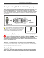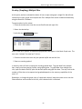
1
IQ3 Data Logger Dash Installation Manual
Disclaimer
Competition Systems, Inc/Racepak make no representations or warranties of any type with
respect to the contents in this manual. Competition Systems, Inc/Racepak disclaim any implied
warranties or fitness for any particular purpose. Competition Systems, Inc/Racepak is not liable
for any errors contained within or for incidental or consequential damages in connection with
the supply, performance or use of the hardware and software or this manual.
Competition Systems, Inc/Racepak reserve the right to revise this installation and user manual
at any time, without obligation to notify any person of revisions.
Warranty
Competition Systems, Inc/Racepak make every effort to insure our products and services are of
the highest quality and standards. It is our intention to maintain a mutually beneficial and
cordial relationship with each and every customer.
Competition Systems, Inc/Racepak warrants all merchandise manufactured by Competition
Systems, Inc/Racepak against defects in workmanship or material for a period of six months
after the data of purchase. This warranty applies to the first retail purchaser and covers only
those products exposed to normal use or service. It does not apply to those products used for a
purpose for which said products were not designed, or which has been altered in any way that
would be detrimental to the performance or life of the product, or misapplication, misuse,
negligence, or accident. Any part or product found to be defective after examination by
Competition Systems, Inc/Racepak will be repaired or replaced. Competition Systems,
Inc/Racepak assumes no responsibility for diagnosis, removal and/or installation labor, loss of
vehicle use, loss of time, inconvenience or any other consequential expenses.
This warranty is in lieu of any other expressed or implied warranties, including any implied
warranty or merchantability or fitness, and any other obligation on the part of Competition
Systems, Inc/Racepak, or selling dealer.
If you have any questions regarding warranty, please contact customer service at Competition
Systems, Inc/Racepak. 949-709-5555
IQ3 Data Logger Manual v2 – March 2008
Racepak, IQ3 Data Logger and Vnet are trademarks of Competition Systems, Inc. /Racepak
© Competition Systems, Inc. /Racepak
1
IQ3 Data Logger Dash Installation Manual
2
IQ3 Data Logger Dash Installation Manual
Disclaimer...........................................................................................................1
Warranty............................................................................................................1
Manual Summary................................................................................................6
Items Included With the IQ3 Data Logger Dash PN 250-DS-IQ3LD ....................................................................................6
IQ3 Features.......................................................................................................7
Display Dash.................................................................................................................................................................................7
Data Logger ...................................................................................................................................................................................7
Base IQ3 Downloaded Data.......................................................................................................................................................7
External Sensors...........................................................................................................................................................................8
Multiple Motorsports Usage .....................................................................................................................................................9
Technical Specifications............................................................................................................................................................10
IQ3 Logger Dash Functions ......................................................................................................................................................11
IQ3 Logger Dash Configuration File........................................................................................................................................11
Logging Start and Stop..............................................................................................................................................................11
Download Data ..........................................................................................................................................................................11
DataLink Software.....................................................................................................................................................................11
PC Minimum Requirements.....................................................................................................................................................11
Terminology................................................................................................................................................................................12
Hardware Features ...........................................................................................13
External Dimensions .................................................................................................................................................................13
External Features – Front.........................................................................................................................................................13
ExterExternal Features – Rear.........................................................................................................................................13
Mounting Template – Full Size................................................................................................................................................14
Mounting Template – Full Size................................................................................................................................................15
Installation .......................................................................................................17
Mounting Location....................................................................................................................................................................17
Mounting Orientation of IQ3 – When Used For Track Mapping Purposes.....................................................................18
Accelerometer Calibration.......................................................................................................................................................18
Mounting Orientation of IQ3 – For GPS Speed with No Track Mapping.........................................................................18
Mounting Method .....................................................................................................................................................................18
Power Supply and Grounding..................................................................................................................................................19
Engine RPM Signal.....................................................................................................................................................................19
MicroSD Memory Card.............................................................................................................................................................19
Power/RPM/Programming Button Connector and Wiring................................................................................................20
External Programming Button and Warning Light Wiring DiagramGPS Antenna Mounting.......................................20
GPS Antenna Mounting............................................................................................................................................................21
Programming the Display by External Buttons....................................................22
External Programming Buttons ...............................................................................................................................................22
Factory Default Display Settings .............................................................................................................................................22
Programming Utilizing the DataLink Software.....................................................................................................................22
3
IQ3 Data Logger Dash Installation Manual
Programming Modes ................................................................................................................................................................23
Setup Mode 1 (stationary programming) .............................................................................................................................24
Setup Mode 2 (moving programming) ..................................................................................................................................26
Setting the Start/Finish Location............................................................................................................................................27
Reviewing Lap Times (Lap Time Replay Mode) ....................................................................................................................27
DataLink II Software Installation........................................................................ 27
Data Download Path .................................................................................................................................................................27
PC Requirements .......................................................................................................................................................................28
Software Installation.................................................................................................................................................................29
DataLink II Help Files.................................................................................................................................................................30
Demo Run Data for Various Motorsports .............................................................................................................................30
Serial Com Port Settings...........................................................................................................................................................31
Data Logger and Dash Setup Using DataLink Software ....................................... 32
Motorsports Specific Configuration Files ........................................................... 32
Opening the Configuration File...............................................................................................................................................32
Programming Functions – Data Logger .................................................................................................................................33
Programming the Display Using the DataLink Software...................................... 34
Motorsports Specific Software.......................................................................... 42
Road Racing / Circle Track Configuration File.......................................................................................................................42
Map Setup ....................................................................................................... 42
Write Start / Finish Position to Card......................................................................................................................................45
TrackVision Export Runlog Page .............................................................................................................................................46
Boat Racing Configuration.......................................................................................................................................................47
Prop Speed ..................................................................................................................................................................................47
Prop Slip......................................................................................................................................................................................47
Map Setup ....................................................................................................... 47
Write Start / Finish Position to Card......................................................................................................................................50
TrackVision Export Runlog Page .............................................................................................................................................51
Puller Runlog Pages...................................................................................................................................................................52
Making the Initial Run....................................................................................... 53
Downloading Data.....................................................................................................................................................................53
Session Dialog Window ............................................................................................................................................................54
Map Select Dialog Window......................................................................................................................................................55
Pulling Data - Setting the Zero Start Point - Very Important.............................................................................................57
Create Trackmap (Closed Course) Oval and Road Racing..................................................................................................58
Track Map Creation (Open - Autocross, Solo & Hill Climb)................................................................................................61
Add Map Segments - Closed Course Tracks Only................................................................................................................62
Add Inside / Outside Track - Optional....................................................................................................................................64
Manually Loading GPS Track Maps ........................................................................................................................................65
4
IQ3 Data Logger Dash Installation Manual
Opening a Lap and Graphing Data: Road Racing/Circle Track/ Boats ...................66
Open a Lap..................................................................................................................................................................................66
Distance Mode Graphed Data .................................................................................................................................................67
Speed and Segment Reports ...................................................................................................................................................68
Overlay (Graphing) Multiple Files ...........................................................................................................................................69
Advanced features of the DataLink II Software...................................................70
Runlog Pages - Data Comparison in Report Format............................................................................................................70
Reference and Main Settings for Runlog Data Comparison..............................................................................................71
Graph Scaling Explained ...........................................................................................................................................................72
Graph Scaling Values Changed per Channel .........................................................................................................................73
Chart Scaling Sets - Universal Scaling Settings .....................................................................................................................74
Creating Graph Sets for Display - Quick Graphs...................................................................................................................75
How to Determine the Currently Graphed and Active Channel .......................................................................................76
Averaging Data Using the Averaging Cursor Action............................................................................................................77
Graphing Data from an Entire Run.........................................................................................................................................78
Zoom Command ........................................................................................................................................................................79
Viewing Real Time Data (Telemetry) on your PC.................................................................................................................80
Troubleshooting and FAQ..................................................................................84
No Data Obtained During Run.................................................................................................................................................84
The Word “CARD” Always Appears in the Center of the IQ3 Display..............................................................................84
DataLink will not communicate with the IQ3 when using the serial cable.....................................................................84
Does GPS Always Work?...........................................................................................................................................................85
Will Rain Affect the GPS Signal?..............................................................................................................................................85
Can I Acquire Elevation?...........................................................................................................................................................85
Does the Loss and Gain of Satellites Affect the Data?........................................................................................................85
Speed Accuracy?........................................................................................................................................................................85
Lap time Accuracy?...................................................................................................................................................................85
GPS Data Does Not Start Until Later in the Run...................................................................................................................85
Track Mapping Accuracy?........................................................................................................................................................86
Can I install a larger Memory Card?.......................................................................................................................................86
How can I email a Runfile or Trackmap?...............................................................................................................................86
Should multiple users comparing data from the same track, use different track maps?............................................86
Lap times displayed on the dash vs. lap times from the track map?...............................................................................86
I cannot set Start Finish with the dash?................................................................................................................................87
I lose satellites when I start to accelerate on the track?....................................................................................................87
My data appears incorrect after downloading? ..................................................................................................................87
Vnet Sensor Channels “Flat Line” during portions of the run ...........................................................................................87
Vnet Sensor Channels disappear from Channel Button area ............................................................................................87
Graphed data drops to the bottom of the graph, during a run........................................................................................87
Excessive noise on graphed channels....................................................................................................................................87
Conclusion...................................................................................................................................................................................88
5
IQ3 Data Logger Dash Installation Manual
Manual Summary
This manual makes the assumption that you have installed the most current version of the
DataLink PC software and IQ3 firmware. IQ3 firmware and DataLink updates can be found at
http://www.racepak.com/IQ3Dash/downloads.htm. As of this writing, the most current
DataLink version is 3.1.0.
To compliment the overall simplicity of the IQ3 Data Logger Dash, we have created a User
Manual that is equally simple in usage. The following provides a quick view of the manual
layout:
1. IQ3 Features
a. Dash
b. Data Logger
2. Installation
a. Dash
b. Software
3. Programming The Display
4. Adding Sensors
5. Initial Run Data and Software Usage
Given the variety of motorsports in which the IQ3 Logger Dash is utilized, we have also noted
features specific to a given motorsport within the above sections. This will allow our customers
to quickly reference features that are most relevant to their type of racing.
Items Included With the IQ3 Data Logger Dash PN 250-DS-IQ3LD
Item
IQ3 Data Logger Dash
512MB microSD Flash Card
SD Flash Card Reader
Serial Communication Cable
8 Position Wire Harness
GPS Antenna and Cable
DataLink Software
Installation Manual
Part Number
UNIT-DS-IQ3LD
CARD-MEM-M512
890-SD-RDR 8-1
280-CA-ST140SR
280-CA-HARNIQ3L
ANTG-ANN-05
N/A
MANL-IQ3LD
6
IQ3 Data Logger Dash Installation Manual
IQ3 Features
The IQ3 Logger Dash is a full programmable LCD digital display dash that is equipped with a 32
channel data logger, 3 axis G meter, 512MB microSD card and GPS board all contained inside
the dash housing. This design eliminates the necessity of an external data logger, G meters or
external GPS module.
The IQ3 is a multi-purpose product designed for use in road racing, circle track, driving schools,
pulling, boating, off road, hill climb or any other type of motorsports that can benefit from the
use of GPS data to obtain speed, timing and mapping functions, without the necessity of wheel
speed sensors, beacon receivers or transmitters.
Display Dash
28 programmable items on 4 pages
Programmable sequential shift lights
4 programmable warning lights with on-screen text warning
5 character programmable alpha/numeric text per display channel
Rear mounted Power/Ground/Engine RPM/Programming Button input
Rear mounted GPS antenna connector
Rear mounted Vnet sensor connector
Shielded, anti-glare coated display for sunlight viewing
Metric and English capable
Blue backlight
Gear indicator
Data Logger
512MB microSD memory card
32 Vnet (canbus) sensor inputs
3 axis G meter – Inline / Lateral / Vertical
4 HZ GPS Board
Base IQ3 Downloaded Data
Battery Voltage / Accel G / Lateral G / Vertical G / Engine RPM
Track Mapping / Speed / Lap Time / Lap Number
Full data analysis capabilities
7
IQ3 Data Logger Dash Installation Manual
External Sensors
The IQ3 Logger Dash utilizes Racepak’s Vnet (canbus) sensor input. This design provides the
ability to transmit all sensor data through a single cable. This cable is connected to the 5 pin
Vnet port on the rear of the dash. No sensor wiring harness is required.
To add sensors, the customer simply measures from the IQ3 dash to the mounting location of
the sensor or sensors, and orders the appropriate length pre-terminated Vnet extension cable.
Vnet cables are available in 12” increments and are equipped with a male connector on one
end and a female connector on the opposite end. In the event sensors are mounted in multiple
location throughout the vehicle, simple measure between each sensor location and order the
necessary Vnet extension cables to connect all items to the main Vnet cable routed to the rear
of the dash.
Sensor
Sensor
Vnet Cable
Sensor
Any Vnet sensor currently offered by Racepak may be utilized by the IQ3 Logger Dash. For a
complete listing of available sensors, visit our website located at www.racepak.com or contact
the Racepak customer service department at 949-709-5555 for a catalog. Customer supplied
sensors may also be utilized. Racepak’s USM module (PN: 230-VM-USM) is a four sensor input
module, providing the ability to define each sensor input dependant sensor type.
8
IQ3 Data Logger Dash Installation Manual
Multiple Motorsports Usage
Road Racing / Circle Track Features
Track Mapping with Segments
Lap Time and Lap Number
Predictive Lap Time
Accel G
Lateral G
Battery Voltage
Engine RPM
GPS Speed
When utilized in closed course racing (circle track, road racing, boating) the data logger obtains
GPS data to provide speed and lap time information to the driver. Track mapping with segment
(split) times are derived from GPS and accelerometer data and is available upon downloading to
the user’s PC, in addition to data provided by external sensors connected to the data logger.
Boat Racing Features (requiring lap time and mapping data)
While boat racing utilizes the same above features, Racepak has added additional features
specifically for the boat competitor:
1. Prop Slip: Allows display of Prop Slip on dash. Requires input of prop diameter, prop
pitch and final gear ration, along with a tachometer signal input.
2. User Defined Start / Finish Distance: Dash lap time data is available to the driver upon
marking of the start / finish location while on the course. By providing the ability to
define the distance this GPS point “looks” across the course, lap time data will be
available regardless of the varying width the boat takes as it passes the start finish
location.
Pulling Features
When utilized for motorsports that do not require timing and track mapping information ( such
as pulling) the IQ3 functions as a standard 32 channel data logger, but with the unique ability to
provide an accurate method of obtaining ground speed without the use of vehicle mounted
sensors.
9
IQ3 Data Logger Dash Installation Manual
Technical Specifications
Total Sensor Channels - Defined Below
38
Vnet Data Channels
Internal Channels as defined below
IQ3 Internal Temperature/IQ3 Logger Voltage / Engine RPM / Accel G /
Lateral G / Vertical G / GPS
32
7
Accelerometer Specifications
Sample Rate
Accuracy
Minimum / Maximum Values
100HZ - 3 Axis
1% (excluding vibration affect)
+5 / -5
GPS Information
GPS logging rate
Channels
Antenna
Accuracy
Cold start / Hot start satellite sync time
4 Hz with 100HZ inertial assistance
16
High Gain / Active
2.5 Meters
34 seconds cold / less than 3.5 seconds hot
Memory
Maximum micro SD Card Size
512MB microSD Flash - Included
2GB Maximum
Data Writing Rate
17Kb / sec
Resolution (ADC)
Data Logger
10 bit
Processor Speed
20MHz
Sample (Logging) Rates of Data Channels
IQ3 Internal Channels
Vnet Channels
100 Hz Maximum, user adjustable to 1 Hz
100 Hz Maximum, user adjustable to 1 Hz
Power & Current
Input Voltage
Current Draw
Reverse Voltage Protection
10-16V
350mA - Without warning and shift LED’s active
Yes
Operating Temperature
32 - 140F / 0-60C
Mounting Orientation
Level left & right / Level top & bottom
Rear of dash facing direction of travel
Engine RPM Input
50% duty cycle, 5-18V square wave signal
Start Logging Channel (factory default)
GPS Speed (25 MPH)
10
IQ3 Data Logger Dash Installation Manual
IQ3 Logger Dash Functions
The IQ3 Logger Dash is the main component of the data system, as it contains the data logger,
512MB memory card, GPS board and G meters.
IQ3 Logger Dash Configuration File
The Configuration File contains the programming settings for both the dash and any internal
and external sensors utilized by the IQ3 Logger Dash. Any additional sensors that were not
shipped with the IQ3 Logger Dash will require updating the Configuration file.
Logging Start and Stop
Any active channel may be used to start logging. From the factory, the IQ3 is programmed to
start logging at 25 GPS MPH (40 KPH) and stops logging when no speed is detected for at least
30 seconds. A data file is written each time the vehicle exceeds the start logging speed
following at least 30 seconds of no speed, and is numbered in subsequent order (1,2,3,etc). The
start logging channel may be changed to any valid sensor channel, by the user.
Download Data
Data is stored on a 5128MB microSD flash card supplied with the IQ3, and is downloaded via a
customer supplied microSD flash card reader to the user’s PC utilizing the DataLink software.
DataLink Software
The DataLink software is used to both set up (configure) the IQ3 data logger and provide the
ability to download and analyze data. Data stored on the microSD flash card is downloaded and
converted into a format (.rpk) that is recognized by the DataLink software. This .rpk file is then
saved to the user’s PC, for analysis.
PC Minimum Requirements
Windows® 98 / ME / 2000 / XP or Vista operating system / 200MHZ (Pentium II) processor
200MB of available hard drive / 16MB of RAM CD ROM drive
Serial port or USB to serial adapter / 1024 x 768 or higher monitor resolution
11
IQ3 Data Logger Dash Installation Manual
Terminology
In order to assist in the installation and usage of the IQ3, the following provides an outline of
the most commonly used words that will be encountered in this manual.
Analog: Data created by the reading of a voltage change sent from a sensor
Calibrate: The process of assigning values to sensor voltage output, in order to graph and
analyze the sensor data.
Canbus: The specific name of the technology utilized to create the Vnet sensor system
Channel: The input from one sensor, as defined by the data logger.
Data Logger: See Data Recorder
Data Recorder: The vehicle mounted hardware device that collects and stores data transmitted
from the sensors
Digital: A sensor or signal that has only two values, off or on such as the measuring of ignition
pulses to calculate Engine RPM
Download: The process of transferring data saved on the data logger memory card to the user’s
PC using the DataLink software, in order to graph and analyze data. Memory card data must be
downloaded through the DataLink software and cannot be open directly from the memory card.
Filter: The process of smoothing the visual appearance of a graphed data channel.
Graph: A visual representation of sensor data, compared to time or distance
HZ: Number of times per second. Used to define logging or sample rate. Example: 4Hz
represents data that is saved 4 times (every .250) per second.
KB: Abbreviation for kilobyte, which represents one thousand bytes of information.
Logger: See Data Recorder
Logging Rate: The number of times per second, which the data logger records incoming data
from a sensor and is defined as Hertz, or Hz. Each sensors logging rate may be define by the
user.
Math Channel: A data channel created from the input of an actual sensor which is then used in a
mathematical formula to create a channel available for graphical analysis
MB: Abbreviation for megabyte, which represents one million bytes of information.
Overlay: The ability to graph multiple data channels, all at the same time.
Runfile: The file created when a run is transferred from the data logger memory card to the
user’s PC. Configuration File
Sample Rate: See Logging Rate
microSD Memory Card: Micro Secure Digital compact flash memory card
Sensor: A device that converts a physical property, such as pressure into a voltage signal
Smooth: See Filter
Start Logging Channel: The channel that is used to start the logging process
Trace: This term is another method used to describe Graph
Transducer: See Sensor
Vnet Channel: Any sensor that is connected to the Vnet port of the data logger
Vnet: Racepak exclusive that allows multiple sensors ( analog or digital) to transmit their data
over a single cable, back to the data logger.
12
IQ3 Data Logger Dash Installation Manual
Hardware Features
External Dimensions
2.1” (5.3cm)
4.1” (10.5cm)
7.3” (18.6cm)
1” (2.54cm)
External Features – Front
microSD Memory Card Slot
Shift Lights
Shift Lights
Warning 2
Warning 3
Warning 1
microSD Memory Card Slot
Shift Lights
Warning Lights 1 &2
Warning Lights 3 & 4
Warning 4
Insertion location for microSD memory card
Fully programmable sequential shift lights
Fully programmable warning lights for Inputs 1 & 2
Fully programmable warning lights for Inputs 3 & 4
13
Exter
IQ3 Data Logger Dash Installation Manual
External Features – Rear
GPS Antenna Connector
Deutsch 8 Pin Connector
Serial Cable Connector
Mounting Studs / Nuts (3 total)
Vnet Connector
GPS Antenna Connector
Vnet Connector
Deustch 8 Pin Connector
Serial Cable Connector
Mounting Studs & Nuts
Provides connection for external GPS antenna
Provides input for external sensor(s) Vnet cable
Provides input for power / ground/ engine rpm /
programming buttons
Provides input for serial cable supplied with package
Three #10 studs and 10-32 nuts facilitate mounting
14
IQ3 Data Logger Dash Installation Manual
Mounting Template – Full Size
15
IQ3 Data Logger Dash Installation Manual
16
IQ3 Data Logger Dash Installation Manual
Installation
The design of the IQ3 greatly simplifies the installation process, as there is no external data
logger or related components necessary. However, there are basic guidelines that must be
followed, in order to insure correct operation of the product.
Mounting Location
The IQ3 is designed to be utilized in a race vehicle environment and as designed as such.
However, there are external conditions that can influence the operation and longevity of the
product.
Heat
Avoid excessive heat, such as generated from exhaust systems, transmissions, etc.
Electrical Interference
Avoid electrical interference. Race vehicles
generate electrical interference from a variety of locations such as ignitions, alternators, ECU,
spark plugs, coils and radio/telemetry antennas. This interference can affect the data generated
by any or all of the sensors.
Moisture
Avoid excessive moisture. The logger is designed to be water resistant but not waterproof. If
washing the vehicle, cover before washing. Wipe any remaining moisture off of the IQ3, when
finished. Protect the microSD card slot from moisture.
Easy Access
Do not mount the IQ3 in a location that makes it difficult to access the memory card or any
connectors.
Movement
It is important to insure the IQ3 cannot become dislodged during use. Three #10 studs are
provided in order to provide secure mounting.
17
IQ3 Data Logger Dash Installation Manual
Mounting Orientation of IQ3 – When Used For Track Mapping Purposes
The IQ3 contains inline, lateral and vertical accelerometers that perform two functions. First is
for graphical analysis of G data. The second is to work in conjunction with the GPS data to
provide track mapping information. The logger must be mounted in the direction shown below
as the orientation of the G meters cannot be re-defined in the software, if mounting in any
other direction.
Direction of travel
Perpendicular to travel
The IQ3 should be mounted as level as possible left
and right, top to bottom and perpendicular to travel.
The dash can be tilted top to bottom up to 45 degrees,
as the G meters can compensated and reset to zero.
No greater than 45°
Accelerometer Calibration
Upon mounting of the dash, it will be necessary to compensate and “zero” the G
meters, to correct for vertical dash tilt. Please refer to the section Setup Mode 2 of this
manual, for complete details. NOTE: Accelerometers cannot be re-oriented in the
software, only compensated to correct for top / bottom tilt. Do not mount the dash rotated in
relation to the travel of the vehicle.
Mounting Orientation of IQ3 – For GPS Speed with No Track Mapping
In certain motorsports, such as pulling, the IQ3 mounting orientation may vary as needed per
the vehicle. Be aware this will skew G meter data.
Mounting Method
Three #10 studs, washers and nuts are supplied with the IQ3, to be utilized for mounting. If
desired, the studs can be unscrewed from the threaded inserts located in the dash housing.
18
IQ3 Data Logger Dash Installation Manual
Power Supply and Grounding
The IQ3 should be connected to a battery source that can supply a constant 10-16 volts. In
vehicles that utilize a master power switch, it recommended to connect to the master power
switch. This not only insures the IQ3 will be powered when the vehicle is in use, it also insures
power will be disconnected in the event of an emergency.
A good ground is very important to the function of the IQ3. Insure there is no type of paint, rust
or any other type of material that could prevent proper grounding. Boats often present unique
grounding problems. If necessary, provide an isolated power and ground as faulty grounds will
create corrupt data.
Warning: Do not attempt to connect or disconnect any IQ3 item, with the power
switched on. This action could result in damage to the IQ3.
Engine RPM Signal
Requirements: 5-18V, 50% duty cycle, square wave output. This signal is typically obtained from
the tach signal output of an aftermarket ignition box. Racepak also offers a GMR Inductive RPM
Pickup (Racepak PN: 680-SN-GMR) which is attached to the +12V coil power on coilpak or coil
on plug ignition systems. For early model points/distributor ignition systems, MSD offers a tach
signal generator, PN 8913 that can be spliced into the 12V power to the coil.
Warning: Do not connect the tach input wire directly to any part of the ignition coil.
Doing so will result in damage to the logger.
MicroSD Memory Card
The IQ3 is equipped with a 512MB microSD memory card. This card is located in the face of the
IQ3, between the shift lights. The card may be removed by simply pressing on the card, which
will slightly eject the card from the dash face. When inserting the card, insure it firmly “clicks”
into place. The edge of the card should slightly protrude from the dash face, when seated. A
larger memory card, up to 2GB, may be utilized.
19
IQ3 Data Logger Dash Installation Manual
Power/RPM/Programming Button Connector and Wiring
The rear of the IQ3 contains an 8 position Deutsch connector. This connector provides the
power and ground inputs, in addition to engine RPM, optional external program button inputs
and external warning light output. The IQ3 is provided with the appropriate 8 position mating
connector and wiring.
Pin Number
1
2
3
4
5
6
7
8
Function
Button 1
IQ3 Power
Button 2
Button Ground
Do Not Use
Tach
IQ3 Ground
External Warning
Wire Color
BLUE
RED
WHITE
BLACK
NOT USED
YELLOW
BLACK
ORANGE
External Programming Button and Warning Light Wiring Diagram
BUTTON WIRING DIAGRAM
EXTERNAL WARNING WIRING DIAGRAM
WARNING LIGHT
PUSH BUTTON SWITCH
to IQ3 connector
chassis
ground or
IQ3 pin 4
to IQ3 connector pin 8
20
to 12v vehicle power
IQ3 Data Logger Dash Installation Manual
GPS Antenna Mounting
The GPS antenna is a moisture resistant, magnetic based type, designed to be mounted on the
exterior roof of the vehicle. If no roof exists or the vehicle is of a composite type, insure the
antenna is mounted in clear view of the sky, with no obstructions. The antenna must be
mounted at the highest point of the vehicle and level front / rear and left / right. Insure the
GPS antenna cable will reach the data logger, before final mounting of the antenna.
GPS antenna mounting for stock bodied vehicles
The GPS antenna is provided with a magnetic mounting base and should always be mounted on
the roof of the vehicle, centered within the roof area. Insure the antenna is as level as possible,
left to right and front to rear. In the event of a vehicle with a composite roof, Velcro can be
utilized. Place a strip of masking tape on the roof of the vehicle. A small piece of Velcro on the
antenna and the tape will be sufficient to hold the antenna in place. We understand the value
of high performance vehicles and the fact some users will be hesitant to place any type of tape
on the surface of their vehicle. In that is the situation, determine the mounting method you are
most comfortable with, but will locate the antenna on the roof area.
GPS antenna mounting for open wheel vehicles
By following the above instructions, simply insure the antenna is mounted as high as possible
on the vehicle. Various body panels can possible block satellite signals. Insure telemetry or two
way radio antennas will not provide interference to the antenna.
Again, the GPS antenna will function well, in a variety of roof mounted locations. The above
guidelines will insure the most efficient reception of signals. The antenna has been roof
mounted and tested at speeds over 190 mph, so feel free to go at least that fast.
Connection of the GPS antenna to the IQ3
Upon completion of mounting of the antenna, simply route the cable to the rear of the IQ3 and
connect to the GPS antenna port of the data logger. Insure the cable end is screwed tightly to
the GPS connector. A small wrench can be used to slightly SNUG the connector. Excessive
force can damage the connector, resulting in failure of GPS signal reception.
21
IQ3 Data Logger Dash Installation Manual
Programming the Display by External Buttons
External Programming Buttons
A variety of IQ3 display functions can be controlled, displayed or programmed through use of
two external programming buttons known as Button 1 and Button 2. This enables the driver to
make immediate changes, without the necessity of connecting a PC to the dash. Instead of
mounting the programming buttons in the dash, Racepak provided the ability to remote mount
the two programming buttons, for better driver access.
Racepak offers a Programming Button Package PN: 280-SW-IQ3 or the customer may provide
their own momentary contact button. If buttons other than Racepak are utilized, insure they
are normal open momentary switches and they are capable of withstanding the environment in
which they will be utilized. The buttons are connected to the 8 pin Deutsch connector located
on the rear of the IQ3. Refer to the Power/RPM Connector and Wiring section of this manual
for pin out instructions.
Many of the programming functions found in the following section may also be performed
through us of the DataLink software and users PC. Those instructions can be found in the
section Programming Utilizing the DataLink Software.
Factory Default Display Settings
From the factory, Page 1 of the IQ3 is programmed
to display the following items. The remaining three
display pages are not programmed from the factory,
which allows for customized programming by the
customer.
Note: The center position will display the number of
satellites locked in when the vehicle speed is below 5
MPH/KPH.
Programming Utilizing the DataLink Software
Many of the programming functions found in the following section may also be performed
through us of the DataLink software and users PC. Those instructions are explained in this
manual.
22
IQ3 Data Logger Dash Installation Manual
Programming Modes
Programming functions of the IQ3 are accessed by using Button 1 and Button 2. Button 1 is
considered Left Button and Button 2 is considered Right Button. It is recommended the two
programming buttons be mounted as Left and Right, in relation to the driver’s position viewing
the dash. There are two programming modes available.
Setup Mode 1 (Stationary): Utilized to program items such as screen brightness or pulses
per revolution (tach programming).
Setup Mode 2 (Moving): Utilized to program the system while the vehicle is moving and or
the engine is running. This is necessary as several settings utilize actual data taken from speed
or rpm, in order to program.
Button Functions
Button Type
Setup Mode 1
Setup Mode 2
Button 1 (left button)
Enters Programming
Adjusts Settings
Advances To Next Page
Saves Changes and Exits
Advances To Next Page
Saves Changes and Exits
Enters Programming
Adjusts Settings
Button 2 (right button)
As can be seen above, the buttons perform the opposite functions depending on the mode.
Since the IQ3 only utilizes two buttons, it was necessary to allow multiple uses for each button.
The length of time the button is held down determines the programming action taken. The shift
lights are used to indicate the action taken with each button.
The following instructions will refer to short, medium and long button press lengths. This is the
length of time the button is held down and the corresponding shift light blink.
Type of Button Press
Length of Time
Shift Light Flash
Short Press
Medium Press
Long Press
Auto Repeating Long Press
.2 Second
.5 Second
2 Seconds
3 Seconds
One Flash Of Shift Lights
Two Flash Of Shift Lights
Three Flash Of Shift Lights
Repeats Every .2 Seconds
The point at which the button is released determines the type press that is accepted. Releasing
after the second shift light flash is detected as a medium length press.
The programming functions are arranged in a pre-defined order. This allows the customer to
enter the programming mode, and then toggle through to the desired feature, by using the left
or right button, depending on the mode.
23
IQ3 Data Logger Dash Installation Manual
Setup Mode 1 (stationary programming)
Setup Mode 1 is used to program the unit without the need to operate the vehicle.
Entering Setup 1
1. Press and hold Button 1 (left button) for TWO shift light blinks – MEDIUM press
2. The Dash will display SETUP 1?
3. Confirm by pressing Button 1 for ONE shift light blink – SHORT press
The following are in the order in which the individual programming features will appear.
Setting as
Displayed on
Dash
BACKLIGHT
TACH PULSES
SHIFT STEP
Program
Setting Description
Programming
Command
Accept and
Advance
Accept and
Exit
0 = Off
9 = Max Brightness
Short Press
Button 2 to
increase value
Short Press
Button 1
Long Press
Button 1
Short Press
Button 1
Long Press
Button 1
Short Press
Button 1
Long Press
Button 1
Short Press
Button 1
Long Press
Button 1
Number of pulses ignition
fires per revolution
V8=4
4 Cyl=2
0=Min
20=Max
Programs RPM between
each shift light. Example:
If shift point is 5000 rpm
with a 100 step, first shi ft
light illuminates at 4600
RPM. Multiply your Step
setting by 4 and subtract
from Shift Point to
determine start of shift
light
Short Press
Button 2 to
increase value
Short Press
Button 2
Advances by 10
Medium Press
Button 2
Decreases by 10
Long Press
Button 2
Quickly advances
Short Press
Button 2
Advances by 10
SHIFT GEAR X
X=Gear number
Program shift point for
each gear.
Medium Press
Button 2
Decreases by 50
Long Press
Button 2
Quickly advances
24
IQ3 Data Logger Dash Installation Manual
Setting as
Displayed on
Dash
Program
Setting Description
Programming
Command
Medium Press
Button 2
Decreases by 5
Requires tach signal
Recommend
programming in Setup
Mode 2
TIME ZONE GMT
SPEED UNITS
S/F DETECT
10/20/40/80/160/320
DEFAULT DISPLAY
Accept and
Exit
Short Press
Button 1
Long Press
Button 1
Short Press
Button 1
Long Press
Button 1
Short Press
Button 1
Long Press
Button 1
Short Press
Button 1
Long Press
Button 1
Short Press
Button 2
Advances by .1
Ratio between engine
RPM and GPS speed
(not final drive ratio)
GEAR RATIO X
X=Gear Number
Accept and
Advance
Long Press
Button 2
Quickly advances
Short Press
Button 2
Increases by 1
Sets data and time
stamp on run file,
based on customer
location time zone in
relation to GMT.
East coast standard
time USA = -5 GMT
Defines Speed in MPH
or KMH for dash display
purposes
Distance in meters, in
which the start/finish
point is projected
perpendicular to
vehicle. Typical utilized
by boat racers.
Medium Press
Button 2
Decreases by 1
Short Press
Button 2
Toggles MPH and
KPH
Short Press
Button 2
Advances
Default page on power
up. If all positions are
disabled, that page will
not be displayed.
1 = Min
4 = Max
Short Press
Button 2
Advances
Short Press
Button 1
Long Press
Button 1
Short Press
Button 2
Advances by 10
ODOMETER
Medium Press
Button 2
Decreases by
1000
Odometer value
Long Press
Button 2
25
Short Press
Button 1
Save and exit
Setup Mode 1
Long Press
Button 2
Save and exit
Setup Mode 1
IQ3 Data Logger Dash Installation Manual
Setup Mode 2 (moving programming)
Setup Mode 2 allows the user to utilize inputs from the moving vehicle, in order to automate
the programming process.
The following are in the order in which the individual programming features will appear.
Entering Setup 2
1. Press and hold Button 2 (right button) for TWO shift light blinks – MEDIUM press
2. The Dash will display SETUP 2?
3. Confirm by pressing Button 2 for ONE shift light blink – SHORT press
Setting as
Displayed on
Dash
TACH CAL
GEAR RATIO X
X=Gear Number
Program
Setting Description
Calibrate tach input with engine
running.
1. With vehicle in parked position,
start engine and bring to 2000 RPM
and hold
2. Long Press Button 2
Calibrates gear ratio for Gear Indictor.
1. Insure tach input is functioning. The
value -0.1 will display if no tach or
speed.
2. Drive car in first gear
3. When speed and RPM are constant
Long press Button 2
4. Dash gear indicator will advance to
next gear
5. Repeat process for remaining gears.
Program any unused gears the
same as your highest gear.
Calibrate
Setting
Accept and
Advance
Accept and Exit
Long Press
Button 2
Short Press
Button 1
Long Press
Button 1
Long Press
Button 2
Short Press
Button 1
Long Press Button 1
Short Press
Button 1
Long Press Button 1
ACCEL CAL
Vehicle must
park on a flat
and level
surface.
Provides ability to compensate the
forward and vertical accelerometers
for top to bottom tilt.
Long Press
Button 2
NOTE: With the exception of the accelerometer calibration, SETUP Mode 2 programming
requires the vehicle to be running and/or in motion. Care should be taken when driving
the vehicle to insure safe operation. If possible, take a passenger along to operate the
IQ3 and perform the calibration procedures.
26
IQ3 Data Logger Dash Installation Manual
Setting the Start/Finish Location
There are two methods you can use to set the start/finish location. The first method is to use
the external programming buttons. The second method is to use the DataLink software to
write the start/finish location to the microSD card. The second method is explained later in the
manual. To set the set start/finish position using the external programming buttons perform
the following:
1) Press and hold Button 1 for 3 LED flashes or until the text SET START/FINISH appears on
the bottom of the display.
2) Drive the vehicle at a speed no less than 10 MPH towards the start/finish location.
3) Press and release Button 1 (1 LED flash) at the point you wish to set the start/finish.
4) The dash will respond YES if successful and NO if unsuccessful.
Reviewing Lap Times (Lap Time Replay Mode)
You can review your lap times from the previous session by entering in to Lap Time Replay
Mode. To enter Lap Time Replay Mode enter a long button press (3 flashes) on button 2. The
text “Lap Replay Mode” will display across the bottom of the display. While in Lap Time Replay
Mode buttons 1 and 2 will perform the following functions.
Type of Button Press
Button 1
Button 2
Short Press – 1 flash
Medium Press – 2 flashes
Long Press – 3 flashes
Decrement Lap Number
Jump to Best Lap
Jump to First Lap
Increment Lap Number
Exit Lap Time Replay Mode
Jump to Last Lap
DataLink II Software Installation
Data Download Path
The key to understanding the DataLink software utilized by the IQ3 is to understand the
relationship between the downloaded data, the IQ3 Configuration file and the DataLink
software.
Raw Data from IQ3
MicroSD memory card
Configuration File in
DataLink Software
27
Datalink II Software
IQ3 Data Logger Dash Installation Manual
Downloaded Data: Stored IQ3 data is downloaded to the user’s PC by means of the IQ3
microSD memory card. Before the data can be opened into the DataLink software, it must first
pass “through” the Configuration file.
Configuration File: The IQ3 Configuration file, contained within the DataLink program, is
automatically loaded with the installation of the DataLink software. The Configuration file
contains all the information necessary to convert the raw data saved on the memory card into a
format that allows the file to be opened in the DataLink software.
The configuration file is a “template” for all downloaded data, containing channel names,
calibration values and scaling values, along with programming features such as the start data
logging channel, etc.
DataLink Software: The Datalink II software provides the ability to open and graph data
contained in a runfile. The DataLink is software is generic in nature, in that it does not store
information related to the data logger setup. Instead, the software contains settings relevant to
the graphing of data and the user’s PC setup.
PC Requirements
PC Hardware Requirements
• USB Port
• Serial Communications Port or USB to Serial Port Adapter
• CD/DVD drive
• 3 Button Mouse
Note: The use of a mouse with a center button is highly recommended
If your PC does not have a CD drive please contact Racepak and request the optional DataLink II
USB Flash Drive Installation Kit. This kit allows the DataLink II software and license disk to be
installed directly through the computers USB port. The DataLink II software does not require a
CD or Floppy Disk Drive for normal operation.
Screen Resolution
The DataLink II software requires a minimum screen resolution of 1024 x 768. We recommend
the use of the largest and highest resolution monitor that meets your installation and budget
requirements. If your PC is configured with dual monitor support, the DataLink II software has
special features to take advantage of the capabilities. A flat panel (1280 x 1024 resolution)
narrow outline monitor such as those manufactured by Dell and Fujitsu is optimum for high-end
applications.
28
IQ3 Data Logger Dash Installation Manual
PC Software Requirements
The DataLink II software is compatible with Windows 98 Second Edition, ME, 2000, XP and Vista
32. If you have a Windows operating system other than those listed above please contact
Racepak for additional installation assistance. DataLink is not compatible with Apple.
Software Installation
To install the DataLink II software on your PC, perform the following.
1. Turn on the computer and start Windows.
2. Insert the CD labeled Racepak DataLink II Software into the CD drive.
3. The RacePak DataLink II Setup program will automatically start, and the setup
InstallShield Wizard will be displayed. Please note—If you have disabled auto run in your
computer the installation wizard will not automatically start.
4. To manually start the installation program; Select My Computer from the computer
desk top, select the CD drive by clicking on it and double click on Setup to start the
installation program.
5. Read the instructions on the dialog boxes and answer any questions required.
We recommend you install the software in the default directories as indicated during the
installation procedure. This will make it easier for our technicians to assist you at a later date
should you have an application problem. If you install the software in a directory other than
the default directory, please note the install directory, in order to assist our technicians should
a problem arise.
The Install Wizard will automatically create a shortcut on the main desktop for the
RacePak DataLink II program.
MicroSD Flash Card Reader Installation
Data recorded by the IQ3 is stored on a 512MB microSD memory card. In order to transfer the
data to the user’s PC, it is necessary to utilize a microSD memory card reader. A microSD card
reader is included in the IQ3 kit package. The reader requires you to use the provided microSD
adaptor and an available USB port on your PC.
The microSD memory card reader provided with the IQ3 does not support Windows 95 or
Windows 98 operating systems.
29
IQ3 Data Logger Dash Installation Manual
DataLink II Help Files
The DataLink II software includes a complete selection of help files, which can be accessed as
shown below:
Main Menu or any open Dialog Box: To get help for any of the menu items simply highlight the
menu item by placing the mouse cursor over the menu item. Next press the F1 key to display
the help.
Icon Tool Bar: Select the ? button located at the bottom of the icon toolbar. The mouse
cursor will change to a? Position the mouse cursor over toolbar icon for which help is desired
and click the left mouse cursor. Help will be displayed
DataLink Program Screens: Select the ? button located at the bottom of the icon
toolbar. The mouse cursor will change to a? Position the mouse cursor over the section of the
DataLink II screen for which help is desired and click the mouse button. Help will be displayed.
Runlog Pages : To get help on a run log page look for the blue icon with a question mark.
Simply click on the button to display the help for the run log page.
Help from Main Menu: Click on the Help main menu selection and select the Help Topics menu
selection. The Help Topics: DataLink II Applications Help will be displayed. Follow the
instructions included with the help box to navigate thru the online help
Demo Run Data for Various Motorsports
During the software installation, a series of demo runs and an IQ3 demo manual were
automatically installed for the following types of motorsports:
1. IQ3 DemoRC
2. Boat Demo
3. Puller Demo
The IQ3 demo manual can be found by clicking Start->Programs ->Racepak->Docs. Adobe
Acrobat Reader is required to view this file. We strongly recommend reviewing the data before
initial use of the IQ3. It is much easier to learn how to graph and review data in the comfort of
your home as opposed to attempting to learn “on the fly” during a hot day at the race track.
30
IQ3 Data Logger Dash Installation Manual
Serial Com Port Settings
When adding Vnet sensors or programming advanced display functions of the IQ3 dash, it is
necessary to connect the user’s PC to the IQ3 by means of the supplied Communication Cable.
The DataLink software is set from the factory to communicate through COM1 (standard serial
port com number). If your PC is using a different com port number, it will be necessary to match
the DataLink and PC com port settings.
1. Open the DataLink II program. The connection to your PC is made through the 9 pin
serial port, located at the back of the PC or via a USB to Serial Port adaptor.
2. Connect the supplied serial communication cable between your PC serial port or USB to
Serial adaptor and the IQ3. Turn on the power to the IQ3.
3. Click Settings on the main menu bar and select
Scan COM Ports.
4. The DataLink program will check COM ports 1-9
for the presence of an IQ3. If an IQ3 is found,
DataLink will automatically configure the
proper COM port setting for you. If your IQ3
was not found, and you are using a USB to
Serial Port adaptor, insure that you have properly installed the device adaptor driver on
your PC. A driver disk should have been provided on a disk by the adaptor manufacturer
at time of purchase. If you cannot find the device driver disk, the drivers are frequently
available on the manufactures website as a free download.
5. You can also manually configure the COM port
settings under Setting à Preferences.
31
IQ3 Data Logger Dash Installation Manual
Data Logger and Dash Setup Using DataLink Software
Access to data logger, sensor and dash programming functions are contained within the
configuration file. At the time of the DataLink software installation, a set of motorsport specific
configuration files were also installed.
Now that the display features of the dash have been programmed by means of the external
programming buttons and the DataLink software installed, we can now access the appropriate
IQ3 configuration file, in order to complete the initial setup of the data logger.
Motorsports Specific Configuration Files
Racepak personnel have created a variety of Configuration files that are customized according
to the motorsports in which the data system will be utilized. Detailed information concerning
each Configuration file can be found in the Runlog and Configuration File Details section of this
manual.
IQ3_Config: This Configuration file contains a combination of Runlog pages and math channels,
created specifically for motorsports that require track mapping, lap and segment information.
In addition, math channels utilizing shock travel data are included.
IQ3_ConfigM: This is the metric version of the above Config file.
IQ3_ConfigBT: This Configuration file contains Runlog and math channel data specific to the
needs of boat motorsports that require track mapping, lap and segment information.
IQ3_ConfigPL: This Configuration file contains Runlog pages specific to the sport of pulling,
which provides customers the ability to input pull specific information, within each run file.
Opening the Configuration File
1. Open the DataLink software and select File from the main menu area
2. Select Open Car Configuration from the pull down menu.
3. A Select Configuration dialog window will open. A list of folders containing Configuration
files will appear on the left side, while the actual Configuration files appear on the right
side.
4. Select the IQ3 configuration file that is appropriate for your type of motorsports
32
IQ3 Data Logger Dash Installation Manual
Programming Functions – Data Logger
The configuration file should now be open in the DataLink software, as shown below. A
configuration file is always noted by the blue “wrench” tab seen at the top of the file. Note the
Channel Buttons across the top of the configuration file. Any internal or external sensor, gauge
or dash programming functions is accessed through this file.
Programming Functions through Channel Buttons
Access to any programming function is through each rectangular Channel Button, as found at
the top of the configuration file. Channel Buttons represent all the current internal and
external sensors or Intelli-Gauges , along with the individual dash programming pages and data
logger functions.
For example, to review programming for the
Lateral g sensor, place the mouse cursor over the Lateral G
channel button and right click. Each channel button provides
access to:
1. Sensor Calibration Values
2. Sensor Scaling
3. Channel Name
4. Logging Rate
5. Graph Smoothing
Data Logger Programming Features through the Configuration File
Function
Channel Button Name
Action To Access
Start Logging Channel and Value
Start / Finish Line Detection Distance
Track Distance (for predictive lap time)
Channel Name
Calibration Values
Scaling Values (graphed data)
Smoothing (graphed data)
IQ3_Module
IQ3 Module
IQ3 Module
Any active channel
Any active channel
Any active channel
Any active channel
Right Click Over Channel Button
Right Click Over Channel Button
Right Click Over Channel Button
Right Click Over Channel Button
Right Click Over Channel Button
Right Click Over Channel Button
Right Click Over Channel Button
33
IQ3 Data Logger Dash Installation Manual
Programming the Display Using the DataLink Software
Many display functions of the IQ3 can be programmed utilizing the two external programming
buttons, as outlined in the Programming the Display By External Buttons section of this manual,
page 24. However, it is also possible to program many of these same functions along with
additional functions, utilizing the user’s PC and DataLink program.
First, it is necessary to connect the user’s PC to the IQ3 utilizing the Racepak serial cable.
Next, open the DataLink software and the IQ3_Config file and Right click over the IQ3 Logger
Channel Button. This action opens the following window:
Each programming function is accessed by tabs located across the top of the page, as outlined
in the following section.
All programming changes to the IQ3 must be finalized by selecting the Send
Configuration button found in the bottom left corner of each programming page.
34
IQ3 Data Logger Dash Installation Manual
Display Pages
A view representing the current programming of all four display pages is obtained by selecting
the Display Pages tab. Each input is programmed by selected the text box related to that input
area, as indicated by the red line extending down to the dash, from each text box.
Bar Graph (Sweep Tach)
Function
Description
KPH MPH RPM
Channel to Display
Averaging Filter
Minimum Value
Maximum Value
Tag Start Value
Tag Value per 10 Bars
Selection defines channel name on dash
Pull down arrow selects channel for bar graph data
Smooths displayed data. 10 is default
Determines starting point for bar graph
Determine ending point for bar graph
Determines start value for bar graph
Determines value for each 10 bar segment. There
are a total of 8, 10 bar segments for 80 total bars.
Closes window following programming changes
OK
Gear Indicator (center of dash)
Function
Description
Channel To Display Pull down arrow selects sensor channel
Averaging Filter
Smooths displayed data. 10 is default
OK
Closes window following programming changes
Remaining Inputs
Function
Description
Channel to Display
Decimals to Display
Averaging Filter
Channel Tag Text
Pull down arrow selects sensor channel
Number of digits to display after decimal
Smooths displayed data. 10 is default
Name displayed. 5 total characters
As shown above, to program an input area, simply locate the desired sensor channel by use of
the pull down arrow, select the sensor channel, then define the remaining values for Decimals
to Display, etc.
35
IQ3 Data Logger Dash Installation Manual
Warnings
The IQ3 provides the ability to program up to four individual warning channels. The face of the
dash contains four warning lights. Each warning light is associated with a single warning
channel. To program each individual warning channel.
1. Select the “Warnings” tab.
2. Next, left click on the warning light you would like to program. This action will open the
Warning Light text box.
Warning Parameter
Description
Warning Channel
Low Warning Limit
High Warning Limit
Channel Tag
Sensor input to be used to trigger warning.
Sensor value to trigger warning when below this value.
Sensor value to trigger warning when above this value.
Text to be displayed above warning channel value when warning is
activated. 5 chars max.
Triggers warning when sensor value is between Low and High
Warning limits.
Triggers warning when sensor value is below Low Warning Limit
and above High Warning Limit.
Requires that warning 1 and warning 2 conditions are met to
activate warning.
Requires that warning 1 or warning 2 conditions are met to
activate warning.
Text displayed to the left of warning channel value(s) when
warning is activated. 5 chars max.
Time is seconds to delay before warning is activated.
Turns on external warning when warning channel is activated.
Channel Value is Inside Warning Limit
Window
Channel Value is Outside Warning Limit
Window
Warning Input 1 AND Warning Input 2
Conditions Are Met
Warning Input 1 OR Warning Input 2
Conditions Are Met
Warning Tag
On Delay Time
Turn On External Warning
The following section provides an example warning setup.
36
IQ3 Data Logger Dash Installation Manual
Example Warning Setup
As noted in the previous section, the dash warning setup allows the user to trigger a warning
light based on one sensor channel or two sensor channels. In addition, a specific text warning
may be programmed to display, when the warning parameters are met.
In the example setup below, the dash warning was programmed as follows:
Warning Channel One: Oil Pressure below 30 PSI
Text Above Warning Channel One: OIL
Warning Channel Two: Engine RPM above 1000
Text Above Warning Channel Two: TACH
Text To Display When Warning Values Are Met: Oil P
Primary Channel Text
Secondary Channel Text
Warning Light
Warning Text
Primary Warning Channel
Secondary Warning Channel
When at least one programmed warning channel is activated, the warning text will alternate
between the warning channel data the normal display page data once a second.
To clear ALL active warning, enter a SHORT press on Programming Button 1. This will clear the
warnings until the warning channel goes out of warning and then back in to warning again.
37
IQ3 Data Logger Dash Installation Manual
Shift Lights
To program the shift lights, simple determine the RPM Channel to activate the shift lights
(typically Engine RPM) then select the shift point for each gear. Finally, select the RPM Interval
between each shift light.
Example: Shift point for each gear is 5000 RPM. Interval
is 100 RPM. With 5 shift lights in use (10 total lights that
are displayed two at a time), the software will calculate
back from the programmed shift point and start the
shift lights at 4600 RPM and increment to 4700, 4800,
4900 and with all lights on at 5000.
Shift Light Formula: Shift Light Interval x 4 minus Shift
Point = Starting Point of Shift Lights
100 x 4 = 400. 5000 – 400 = 4600 (start of shift lights)
Gear Calculation
The gear position is most easily configured using the IQ3
Setup Mode 2 programming. The IQ3 derives the gear
position by calculating the ratio between the engine rpm
and GPS speed at the time each gear is programmed.
It is also possible to manually enter the ratio values
utilizing the Gear Calculation page. However, the ratio
values are not the transmission or final drive ratios, but
instead is the ratio between engine rpm and GPS speed.
There are two methods to determine the ratio:
1. Driving: Place the vehicle in first gear and accelerate to a steady, slow speed. Note the
engine RPM and the GPS speed. Place the vehicle in second gear and note the engine
RPM and GPS speed. Repeat the process for all gears. Below is the formula utilized.
GPS Speed / Engine RPM (GPS Speed divided by Engine RPM) = Gear Ratio
2. Manual Calculation. This involves calculating the vehicle speed as determined by engine
RPM, gear ratios and tire circumference and applying the above formula to those
calculations. Engine RPM / 1st Gear Ratio / Rear Gear Ratio x Tire Circumference / 12 *
60 / 5280 = Speed (mph)
Calculate the ratio for each gear and insert the ratio in the appropriate input box.
38
IQ3 Data Logger Dash Installation Manual
Slip Calculation
The Slip Calculation provides the ability to display slip
data based on propeller vs. speed or tire vs. speed for
use with wheel driven vehicles. The slip calculation can
only be used for display purposes. It is not recorded on
microSD card. If you need to record a slip calculation,
you can create one via the DataLink software math
channel feature.
RPM Channel to Calculate Slip: Typically Engine RPM or
the rpm channel that provides final drive to the
propeller or wheels.
Speed Channel to Calculate Slip: The sensor channel that provides vehicle speed, which is GPS
MPH in most instances.
Distance of Travel per Revolution: The propeller pitch in inches or centimeter (or drive wheel
circumference).
Gear Ratio: The final drive ratio between the RPM input and the wheel or propeller. For
vehicles that have more than one set of gearing between the engine and wheel or propeller, it
will be necessary to calculate a final drive ratio.
Final gear drive formula for wheel driven vehicles:
Tire Circumference / Drive Ratio = Final Drive Ratio
This number can be entered in the Gear Ratio input area.
39
IQ3 Data Logger Dash Installation Manual
Dash Info
The Dash Info contains setup parameters, specific to the dash and data logger. Locate the
Custom Programming Options area. This is found on the left side of the page.
To change any of the following parameters, place the mouse cursor on the desired text line and
left click. This will activate the input box for the particular setting, to the right of the selected
text line. Changes are entered in the input box, and then sent to the dash via the SEND
Configuration button as found in the lower right corner of the open window.
In some instances, the following settings are also accessed by the external programming
buttons.
Product Version
Same as firmware version.
Record Enable Channel
The sensor channel that starts the process of saving data to the memory card. Any active
channel may be used, to start recording. When powered up, the IQ3 does not save data to the
memory card until the channel value is exceeded as shown below.
Start recording when channel exceeds value
This defines the value that must be exceeded before the IQ3 will start saving data to the
memory card.
Max Number of Seconds to Record
This is the total time (in seconds) that a single data file will record, before the data logger saves
the file and automatically starts a new recording. Do not change.
Start Finish Line Distance
This defines the distance that an “imaginary” start finish line (latitude and longitude) point is
projected left, right and perpendicular to vehicle travel, when the start finish is set utilizing the
external programming buttons. This can be visualized much the same as the distance a
trackside beacon transmitter will project across the racing surface. For land based vehicles, this
is typically not a problem, as the vehicle will consistently maintain a narrow driving line location
on the track.
For boating competitors, this setting is important, as boats can often vary in driving line
locations by large distances. If the Start Finish Line Distance setting is too small, the boat will
“miss” the start finish marker and thus not receive a lap time or numbers.
Minimum is 30 feet / 10 meters, while maximum is 960 feet / 320 meters.
40
IQ3 Data Logger Dash Installation Manual
Odometer Input Channel
If you would like to enable the odometer function, you must first define the speed channel used
to calculate the distance traveled. You must remember that if you select GPS speed, the
odometer will only be functional when the IQ3 has acquired three or more satellites.
Real Time Sample Rate
Defines the logging or sample rate when data is viewed in real time (live watch). Minimum is 1
and maximum is 100.
41
IQ3 Data Logger Dash Installation Manual
Motorsports Specific Software
Each type of motorsports places different demands on the software. As discussed on previously
in this manual, Racepak has created three configuration files, designed to cover a variety of
motorsports. The difference between the configuration files can be found in the Runlog page
area, which is screen area located below the main graph area. Here, the user will find a variety
of pages specific to their type of motorsports. To select any Runlog page, simply left click over
the MENU Runlog tab. This will access the 8 categories of pre-configured Runlog pages. Left
click over any category, to access individual pages.
All Runlog pages are copied into each new run, providing the user an opportunity to insert data
relative to each run. Data inserted remains with each run for current or later data analysis.
Road Racing / Circle Track Configuration File
Session Info and Weather
1. Session
2. Weather
3. Run Comments
Provides an input area for run numbering data, weather conditions and comments. Data is
inserted by the user, as needed
Map Setup
1. Create GPS Map
2. Add Map Segments
3. Add Inside - Outside Track (optional)
Provides an input area to create and segment track data. Additional information can be found
in the following section.
Map Analysis
1. Map Report
2. Lap Zoom
3. Segment Report
4. Segment Compare
5. Speed Compare
6. Min Max Avg Report
7. GG Plot
Provides an input area to review and analyze data. Additional information can be found in the
following section.
42
IQ3 Data Logger Dash Installation Manual
Real Time Displays
1. Dash
2. User Gauges
3. On Track Telemetry
Provides the ability to view data in an analog real-time format. Additional information can be
found in the following sections.
User Defined Runlog Pages
1. User Page 1
2. User Page 2
3. User Page 3
Provides the ability to create custom Runlog pages. Additional information can be found in the
following sections.
Car Setup
1. Chassis Scaling
2. Tire Data
Chassis Scaling Runlog
The function of chassis scales is contained within this Runlog page. By inputting the four corner
weights of a scaled vehicle, the Chassis Scaling page can calculate the following information:
1. Total Weight
2. Cross Weight
3. Cross Weight Percentage
4. Left Side Total Weight
5. Left Side Total Percentage
6. Right Side Total Weight
7. Right Side Total Percentage
8. Front Percentage
9. Rear Percentage
10. Total Left Side Lead
11. Total Right Side Lead
Again, this information may be entered into the Chassis Scaling Runlog page, prior to the start
of testing. This Runlog page can also be used to calculate the set up information, while at the
shop. Simply input the corner weights and the Runlog page automatically provides the above
11 items.
43
IQ3 Data Logger Dash Installation Manual
Tire Data
This Runlog page was designed to provide an area to input tire temperatures and pressure build
up, during track test events. However, the Tire Pressure Cold data should be entered before
the start of testing. Following a test run, if tire temp readings are obtained by means of a hand
held probe, the individual temperatures can be inserted into this Runlog page. By doing so, the
system can provide the following information:
1. Left Front Average 2. Right Front Average 3. Average Overall Front
4. Left Rear Average 5. Right Rear Average 6. Average Overall Rear
In addition, if the cold and hot tire pressure data is inserted, the system can provide the
following information: 1. Left Front / Right Front / Left Rear / Right Rear Pressure Gain
44
IQ3 Data Logger Dash Installation Manual
Write Start / Finish Position to Card
The ability to export the start / finish location (as set in the GPS Trackmap) to the memory card
eliminates the necessity of setting the start / finish from the external programming buttons.
When the card is re-inserted into the data logger, this start / finish location is automatically
installed in the data logger.
To export the GPS Trackmap start / finish location to the data logger:
1. Insure a GPS trackmap has been created for the selected Runfile, following all four steps
found in the Create GPS Track Map Runlog page.
2. Remember to place the start / finish of the GPS trackmap in a location that will be both
familiar to the driver and in an area that lap time data will be easy to read when on the
track. Typically this will be on the front straight of most tracks, as that affords the driver
a bit of time to glance at the lap time and lap number.
3. Select the Runlog Menu tab found at the bottom of the DataLink software.
4. Locate the Write Start/Finish Position to Card button as found under the Favorite Log
Page Shortcuts area.
5. Connect the memory card to your PC via the method used when downloading data to
the user’s PC (typically a USB flash card reader).
6. Select the Write Start/Finish Position to Card button.
This action automatically places the GPS trackmap start / finish position on the memory card.
Following this action, simple insert the memory card into the data logger and apply power.
The start / finish is now set, which will allow the display dash to provide lap time and lap
number information. This start / finish location can be re-set by using the dashes external
programming buttons or by exporting another start / finish location to the compact flash card
(as taken from the GPS trackmap).
WARNING: Do not make any changes to the start finish file that is saved to the memory card.
Editing the name or file type will result in failure to write the start / finish location to the data
logger.
45
IQ3 Data Logger Dash Installation Manual
TrackVision Export Runlog Page
This page allows the user to quickly export data from the DataLink software for use in the
TrackVision video software. This is accomplished through the use of our TrackVision Export
Runlog page. This page can be accessed by selecting the Track Vision Export button found on
the Runlog Menu page, under the Favorite Log Page Shortcuts heading.
The TrackVision Export Runlog page enables the user to quickly export a list of standard
TrackVision related data channels. In addition, the user can also create a customized list of data
channels to be exported for use in the TrackVision software.
Exporting pre-defined TrackVision data channels:
1. Open a Runfile.
2. Select the Run Log Menu Runlog tab at the bottom of the DataLink software.
3. Select the Track Vision Export button found under the Favorite Log Page Shortcuts
heading as shown below.
The user is presented with two options:
1. Export Standard TrackVision Data
2. Export Custom TrackVision Data
Exporting Standard TrackVision Data:
1. Select the Export Standard Track Vision Data button.
2. Data is automatically exported to the following file folder location:
C:\RacePakData\TrackVision_Std.csv
3. Data is now saved and ready for use in the TrackVision software.
46
IQ3 Data Logger Dash Installation Manual
Boat Racing Configuration
Prop Data Math Channels: Racepak personnel have installed a set of math channels that
provide data specific to boat racing analysis. This allows graphing and reviewing of prop data in
the main graph area, but has no affect on Prop Slip settings as programmed in the dash.
Prop Speed
Channel name: Prop Speed
The Prop Speed channel is derived from the input of Engine RPM, Gear Ratio, Prop Pitch and
internal mathematical functions. To activate channel, complete the Prop Data Runlog page.
Prop Slip
Channel name: Prop Slip
The Prop Slip channel is created from the input of GPS MPH and prop speed.
Session Info and Weather
1. Session
2. Weather
3. Run Comments
Provides an input area for run numbering data, weather conditions and comments. Data is
inserted by the user, as needed
Map Setup
1. Create GPS Map
2. Add Map Segments
3. Add Inside - Outside Track (optional)
Provides an input area to create and segment track data. Additional information can be found
in the following section.
Map Analysis
1. Map Report
2. Lap Zoom
3. Segment Report
4. Segment Compare
5. Speed Compare
6. Min Max Avg Report
7. GG Plot
Provides an input area to review and analyze data. Additional information can be found in the
following section.
47
IQ3 Data Logger Dash Installation Manual
Prop Data and Accel Reports
1. Prop Data
2. Accel Times
3. Accel Times Scroll
Prop Data
In order to activate the Prop Slip and Prop Speed data channels, it is necessary to complete the
gear and prop data information contained on the Prop Data Runlog page. le.
Accel Time and Accel Scroll Runlog Page
1. Open a Runfile and Graph GPS_MPH
2. Open the Accel Times Runlog Page
3. Enter the desired speed to start the report and the desired display MPH increments, in
the input area at the top of the page. For example, if 50 MPH is inserted as the Entered
Speed and 10 is inserted in the Display Every time input area, the report will start at 50
MPH and display data in 10 MPH increments.
4. Place the cursor in the Main Graph area, then located the cursor at a starting point in
the GPS_MPH data. Locate the cursor at a point that is below the Entered Speed.
5. Located the Add/Edit Segment Lap Markers icon, on the left side of
the DataLink screen and select it
6. Select the Insert New Lap Marker At Cursor Button
7. Select the Lap Markers channel button, in order to display the inserted marker within
the graph area
8. Move the cursor to the desired ending point of the Accel run and repeat steps 6 and 7
9. If multiple acceleration runs were made during the outing, continue to place markers at
the desired beginning and ending points
10. The DataLink software will review acceleration data between
each marker and provide report data based on those markers
48
IQ3 Data Logger Dash Installation Manual
To utilize the Accel Scroll Runlog page, simply place the mouse cursor over the slider
located at the top of the Accel Scroll Runlog page, right click and hold then drag the slider left
or right to move the accel data accordingly. This feature allows the user to view data that
extends out of view of the screen area.
Real Time Displays
1. Dash
2. User Gauges
3. On Track Telemetry
Provides the ability to view data in an analog real-time format. Additional information can be
found in the following sections.
User Defined Runlog Pages
1. User Page 1
2. User Page 2
3. User Page 3
Provides the ability to create custom Runlog pages. Additional information can be found in the
following sections.
49
IQ3 Data Logger Dash Installation Manual
Write Start / Finish Position to Card
The IQ3 config file provides the ability to export the start / finish location (as set in the GPS
Trackmap) to the memory card. When the card is re-inserted into the data logger, this start /
finish location is automatically installed in the data logger, thus eliminating the need to set the
start / finish location with the Display Dash.
To export the GPS Trackmap start / finish location to the data logger:
7. Insure a GPS trackmap has been created for the selected Runfile, following all four steps
found in the Create GPS Track Map Runlog page.
8. Remember to place the start / finish of the GPS trackmap in a location that will be both
familiar to the driver and in an area that lap time data will be easy to read when on the
track. Typically this will be on the front straight of most tracks, as that affords the driver
a bit of time to glance at the lap time and lap number.
9. Select the Runlog Menu tab found at the bottom of the DataLink software.
10. Locate the Write Start/Finish Position to Card button as found under the Favorite Log
Page Shortcuts area.
11. Connect the memory card to your PC via the method used when downloading data to
the users PC (typically a USB flash card reader).
12. Select the Write Start/Finish Position to Card button.
This action automatically places the GPS trackmap start / finish position on the memory card.
Following this action, simple insert the memory card into the data logger and apply power.
The start / finish is now set, which will allow the display dash to provide lap time and lap
number information. This start / finish location can be re-set by using the Display Dash method
or by exporting another start / finish location to the compact flash card (as taken from the GPS
trackmap).
WARNING: Do not make any changes to the start finish file that is saved to the memory card.
Editing the name or file type will result in failure to write the start / finish location to the data
logger.
50
IQ3 Data Logger Dash Installation Manual
TrackVision Export Runlog Page
This page allows the user to quickly export data from the DataLink software for use in the
TrackVision video software. This is accomplished through the use of our TrackVision Export
Runlog page. This page can be accessed by selecting the Track Vision Export button found on
the Runlog Menu page, under the Favorite Log Page Shortcuts heading.
The TrackVision Export Runlog page enables the user to quickly export a list of standard
TrackVision related data channels. In addition, the user can also create a customized list of data
channels to be exported for use in the TrackVision software.
Exporting pre-defined TrackVision data channels:
4. Open a Runfile that was downloaded utilizing the updated G2X_Config file found in
Version 2.7b or higher of the DataLink software.
5. Select the Run Log Menu Runlog tab at the bottom of the DataLink software.
6. Select the Track Vision Export button found under the Favorite Log Page Shortcuts
heading as shown below.
The user is presented with two options:
3. Export Standard TrackVision Data
4. Export Custom TrackVision Data
Exporting Standard TrackVision Data:
4. Select the Export Standard Track Vision Data button.
5. Data is automatically exported to the following file folder location:
C:\RacePakData\TrackVision_Std.csv
6. Data is now saved and ready for use in the TrackVision software.
51
IQ3 Data Logger Dash Installation Manual
Puller Runlog Pages
Session
Provides an input area for run numbering data, weather conditions and comments. Data is
inserted by the user, as needed.
Pull Info
Provides an area to input pulled related information.
Weather
Provides an area to input weather information.
Vehicle and Track Info
Provides an area to input vehicle setup and track condition information.
Dash Gauges
Allows the user to select the input channel to activate each gauge. Can be used during
telemetry or review of downloaded data.
User Defined Runlog Pages
1. User Page 1
2. User Page 2
Provides the ability to create custom Runlog pages. Additional information can be found in the
following sections.
52
IQ3 Data Logger Dash Installation Manual
Making the Initial Run
Downloading Data
The IQ3 creates a new file and saves all data gathered from the start of logging (speed greater
than 25 MPH) to the end of logging (speed less than 25 MPH for 30 seconds). Each file is saved
in a .ddf format and is assigned a number based on date and time. Multiple files can be saved
to the memory card.
When a .ddf file is transferred to the DataLink II program, it is then assigned a file name based
on the track, date and run number. At that time, it becomes a Runfile. All of the lap data is
contained within the Runfile and is called a Lapfile. While it is not necessary to transfer your
data after each run, it is highly recommended, if at all possible.
Only one Run file can be transferred at a time, so you must perform the following procedure
once for each .ddf data file or recording.
1. Turn off power to the IQ3
2. Open the DataLink II program, and insert the MicroSD memory card into the card
reader.
3. Initiate the download process by selecting the New Download
icon.
4. The Select Configuration dialog window will open. Select the appropriate Configuration
file and OK.
5. The Open dialog window will open. The first time data is
downloaded you will need to select the drive letter
corresponding to the MicroSD card reader.
6. There will be one .ddf file for each recording. In this
example, there are multiple .ddf files. If multiple files are
listed, select the desired file to download and select Open.
7. The file will download and the Session dialog window will open.
53
IQ3 Data Logger Dash Installation Manual
Session Dialog Window
When data is downloaded to the user’s PC, a
download “path” must be created. This process
automatically creates a series of folders for the
downloaded data.
The folders are named based on the number entered
into the Year input box and the location entered into
the Track input box.
It is only necessary to enter the Year one time,
according to the year of testing. It is also only
necessary to enter the Track name one time, at each track.
At the same time, a number must be assigned to the Runfile before the file can be placed into
the designated folder. The Session page provides the ability to assign both the run number and
the location in which to save the Runfile.
An example data path: C\RacepakData\IQ3\2008\Daytona
If 2008 was entered for the Year and Daytona for Track, the above set of folders (or directory)
would be created on the user’s C drive. The Runfile number is assigned according to the date,
location and run number.
1. Enter the appropriate information in the Session dialog box and select Next.
54
IQ3 Data Logger Dash Installation Manual
Map Select Dialog Window
The Map Select Dialog Window is designed to assist the user in selecting previously created and
saved GPS Track Maps. After extended use of the data system, it is possible to have quite a
large collection of saved maps. However, the Racepak engineers have created a unique way to
provide a limited number of maps for selection. Upon download of a new run, the Datalink II
software reviews the location of the vehicle, relative to GPS data. Then, only previously saved
maps that are located within a five mile radius of the newly downloaded run, will be displayed
for selection.
For a run at a new location that does not
detect any previously saved track maps
within that five mile radius, the above Create
New message will appear in the Map Select
Dialog Window. Since these instructions
assume this is the first download for a new
system:
1. Select Next
2. The Weather dialog box will be
presented. If desired, enter the current weather conditions. If not desired, this
information can be entered at a later date, then select OK.
55
IQ3 Data Logger Dash Installation Manual
3. The final dialog window to be presented to the user is the Save window. This allows the
user to review the save location and Runfile number. If any changes are desired, they
made be performed at this time. If no changes are desired, select Save.
At this time, the Runfile is now open the DataLink II software. The next step is to create a GPS
track map. First, we will review the procedures that must be applied to a Runfile, when the IQ3
is utilized by pulling competitors. Creating trackmaps does not apply to our Pulling customers.
56
IQ3 Data Logger Dash Installation Manual
Pulling Data - Setting the Zero Start Point - Very Important
In order for puller competitors to accurately review data, it is necessary to reset the start of
graphed data (Zero Point) for each run. When data is initially downloaded and graphed, the
starting point of the graphed data is when the data logger started saving data to the compact
flash card. For example, if the data logger is set to start logging when engine rpm exceeds 3000,
that point could occur while driving up to the sled, on the first pull. Suppose on the second pull,
the motor does not exceed 3000 rpm until the vehicle is starting the actual pull. When data is
downloaded and graphed, the zero time (or starting point) of the data will be at two totally
different locations. This makes it impossible to accurately overlay and graph data.
The solution to this situation is to manually move the zero time point to the same location,
within each run. This is accomplished by using the Set Start Time icon, located in the DataLink
software. To perform this procedure :
1. Open a Runfile
At this time, it will be necessary to determine what data channel will always be used to
determine the first movement of the vehicle. For pullers, the Accel G channel works well.
2. Graph the Accel G channel.
3. Select the Autoscale icon. This will display all data from beginning to end.
4. Place the cursor in the Main Graph area (the area with the colored graph line)
5. Press and hold down the left mouse button (starting at the very beginning of the run).
6. Drag the mouse to the right until the very first movement of the vehicle is noted.
7. The first movement of the vehicle will be obvious, with an upward spike in Accel G data.
Upward Spike
Determine the first movement of the vehicle by continuing to hold the left mouse button down
and watching the real time Accel G Channel Button data (at the top of the page). The Zero start
time will be when the Accel G Channel Button data begins to increase. When the start of the
run is located:
8. Select the Set Start Time icon
9. The Confirm Data Start Time Change
window will open. Select OK
At this time, the graphed data will now start at the new zero time as set by this action.
NOTE: It is vitally important to perform this procedure on every run, or accurate data overlay will not be possible.
Create Trackmap - Required for Closed Course / Oval & Road Race
57
G2X Pro Installation Manual
Create Trackmap (Closed Course) Oval and Road Racing
Upon download of the initial run, it is advisable to quickly check two channels, to verify system
operation. Two suggested channels are the GPS_MPH and GPS_Satellites. Typically, if those
two channels are correct, all the remaining GPS functions will be correct.
At this time, the initial run should be in view, in the DataLink II software. To graph the
GPS_MPH channel:
1. Place the mouse cursor over the GPS_MPH Channel Button and left click.
2. The GPS_MPH data should now be in view, in the Main Graph area.
3. Locate and left click the Autoscale icon,
located in the vertical icon list on the left
side of the screen. All graphed data, from the start of logging until the end of logging, will
be displayed.
4. Next, graph the GPS_Satellites channel by placing the mouse cursor over the GPS_Satellites
Channel Button and left clicking. This action will display the number of satellites utilized
during this particular run.
5. A minimum of three satellites are required at any given time in a run, in order to produce
valid data. Typically, the logger will utilize between three and seven satellites.
Your screen should appear as shown below:
IQ3 Data Logger Dash Installation Manual
If no previously save track map exists for the newly downloaded data, the next action that must
be performed is the creation of a GPS track map. A GPS track map is the most important item
for data review, as the track map controls all of the timing functions of the logger and DataLink
II software. Without a GPS track map, no lap times, segment times or visual driving lines will be
available.
In essence, the creation of a GPS track map is the same as physically placing start / finish and
segment beacons at various points around the race course. The difference is we are re-creating
the track in the DataLink II software utilizing GPS information, then inserting (in the software)
the start / finish and segment timing points at various locations around the GPS track map.
Those timing points are also GPS plotted positions and provide timing information with the
same accuracy as trackside beacons.
GPS track map files are saved according to the name assigned by the user. Typically, the name
will reflect the name of the track or location in use. Saved GPS track map files can then be
recalled for use, according to the testing location and needs of the user. The procedures for
creating a GPS track map are quick, easy and listed in numerical order, Step 1 through Step 4.
At this time, our initial run data should still be in view. To create a GPS track map, select the
Map Setup Category button, then select the GPS Trackmap Runlog tab, located at the bottom of
the DataLink II screen. The instructions are presented in order from 1 through 4.
Step 1: Select / Create GPS Map
Left click over the Select / Create GPS Map. This opens a Select/Create GPS MAP dialog box.
The user is presented with three choices, which are self explanatory:
1. New (Clear) Lap File: This allows the creation of a new track map.
2. Open Different Lap File: This allows the user to load a
previously created track map.
3. Rename/Save Lap File: This allows the user to rename a
previously created track map or simply save an
existing track map.
For the initial run, we will select New Trackmap and then OK.
The Save As dialog box will now be opened for the user. Simply type the desired track or
location name (example: Road Atlanta) then select the Save button. Following this action, the
user will be returned to the DataLink II software. The Create GPS Trackmap Runlog page will
now display all of the GPS driving data. Remember, at this point the GPS data in view is all data
logged from the start until the end of recording.
59
IQ3 Data Logger Dash Installation Manual
Step 2: Select Track Type
The next step is to assign the type of track in use for testing. Most all testing will be considered
the default setting of Closed Course. Open Course is typically used for events such as Autocross
and Hill Climbing, which is covered in the following section.
Step 3: Set Lap Start
As discussed in the previous section, the current data in view represents the GPS position of the
vehicle from the start until the end of recording. If you were to place the mouse cursor in the
Main Graph area, (insure GPS_MPH is still graphed and the entire run is in view) then left click
and drag the mouse curser through the Main Graph area, you can follow the location of the
vehicle in the GPS driving line data. However, there will be no lap data, until a start / finish line
is assigned.
To Set Lap Start, place the mouse cursor in the Main Graph area,
left click and move the vehicle location (as noted by the small X) in
the GPS map data until the approximate start / finish is located.
Next, simply select the Set Lap Start button. Just consider this
action the same as physically placing a beacon transmitter on the
start / finish line of the race course, except this is much easier.
In order to generate a GPS track map, the final step will be to view a lap and create the map
from that actual lap.
Step 4: Create GPS Map
To view a lap, locate the LAP NUMBER widow shown under Step 4. By using the Up / Down
arrows, the user can toggle through all of the laps contained within the run. To select a lap,
simply choose a lap that represents a complete, high speed lap. This lap will also be utilized to
generate segment timing, so choosing a high speed lap with the greatest lateral g forces, will
assist in the segmentation.
Now, select the Create GPS Trackmap button. This action now completes the GPS track
mapping process. As with many activities, the actual explanation of the track mapping
procedure appears extensive, while the actual process takes less than 30 seconds.
60
Vehicle
Location
IQ3 Data Logger Dash Installation Manual
Track Map Creation (Open - Autocross, Solo & Hill Climb)
Through the use of GPS signals, it is possible to create a track map, even if the start and finish
line are located at two different locations. In the previous section, we located the vehicle at the
desired start / finish and selected the Set Lap Start button. For open course, we need to also
establish an end point of the lap, also. To create an open course track map, we will refer to the
previous section and follow the same instructions for Step 1. Resuming at Step 2:
Step 2: Select Track Type
For open course, select Open Course.
Step 3: Set Lap Start
Set Lap End / Open Course Only
As discussed in the previous section, the current data in view represents the GPS position of the
vehicle from the start until the end of recording. If you were to place the mouse cursor in the
Main Graph area, (insure GPS_MPH is still graphed and the entire run is in view) then left click
and drag the mouse curser through the Main Graph area, you can follow the location of the
vehicle in the GPS driving line data.
To Set Lap Start, place the mouse
cursor in the Main Graph area, left click
and move the vehicle location (as noted
by the small X) in the GPS map data
until the approximate start area is
located. Next, select the Set Lap Start
button. Then, move the cursor to the
desire end of the course and select the
Set Lap End button.
Step 4: Create GPS Trackmap
Finally, select the Create GPS Trackmap button. This action now completes the GPS track
mapping process.
61
IQ3 Data Logger Dash Installation Manual
Add Map Segments - Closed Course Tracks Only
Now that we have created a GPS track map, the next step is to create track segments. In order
for the DataLink II software to provide segment data, it is necessary to break the track into
corners. Each corner will represent the start and end of a timing segment. However, in this
instance, we will use Lateral G forces to create the segments for us. By doing so, it automates
the process and eliminates the necessity of manually assigning segments.
Open the Add Map Segments Runlog page. Next, graph the Lateral G channel. Review the data
and determine the approximate Lateral G value obtained upon entry to most of the corners.
Next, determine the approximate Lateral G value upon exiting most corners. At high speed,
high lateral g force tracks, it is recommended to attempt to maintain at least .5 G difference
between the maximum and minimum values. Following this:
Step 1: Open Lap
To generate segments, it is necessary to open a lap. Use the same lap as previously selected to
generate the track map.
Step 2: Generate Segments
1. Insert the desire maximum Lateral G value in the Corner Start input box
2. Insert the desired minimum Lateral G value in the Corner End input box
3. Select the Generate Segments button.
Following this action, the DataLink II software will segment the GPS track map, and assign
names to each corner. Often times, a road course will assign a variety of names, to the same
corner. For example, the DataLink II software will assign a Turn 7 and Turn 8 to the track map.
However, the “official” name for the turn could be shown as Turn 7a and Turn 7b and Turn 7c.
In this case, the user may insert a variety of Lateral G values to create the approximate correct
number of turns. When creating circle track segments, the system will automatically create only
two turns. In order to divide the track into four corners, it will be necessary to manually edit the
segments, as reviewed in the following section.
Note: The factory default setting for Corner start is 1, while Corner End is .5. These
values are just a starting point and should be adjusted by the user, depending on the
cornering forces of the vehicle.
62
IQ3 Data Logger Dash Installation Manual
Step 3: Manually Edit Segments
It is also possible to manually name a particular turn, override the assigned name to a particular
area of the track or creating additional segments by using the Manual Segment Edit. To do so:
1. Position the location of the vehicle (as noted by the X on the track map) in the desired
change area. Select Divide. Move the cursor to the desired ending point of the change
select the Divide button again.
2. Place the location of the vehicle between the newly selected Diving markers and choose
the desired action: Corner / Straight / Merge / Extend / Divide and the DataLink II
software will perform the desired changes.
Road course: We have found it is helpful to obtain a top view of the race course (most are
available on the Internet) and duplicate their nomenclature for corners and straights. This
agreement between maps will greatly assist, when discussing particular track areas.
Circle Track: To create a four turn track, place the mouse cursor in the Main Graph area and
move the vehicle location to the center of turn 1, then select the Divide button. Next, place the
mouse cursor in the Main Graph area and place the vehicle location in the center of the
opposite turn and select the Divide button. This action will now provide a four turn track.
Additional segments may be created by placing the vehicle in the desired location and
continuing to divide the track map.
Remember, any segment added to the track map provides timing information, which aids in
data analysis.
To manually insert segment markers at desired locations on the track map, position the vehicle
at the desired location for the entrance segment marker and select the Divide button. Next,
move the vehicle to the desired exit segment marker and again select the Divide button. Then,
place the vehicle position between the two segments markers that are in view on the track map
and select the Corner button.
63
IQ3 Data Logger Dash Installation Manual
Add Inside / Outside Track - Optional
When utilizing GPS data, it is possible to create on-screen inside and outside track edges, to
assist in reviewing data. To obtain data for inside / outside driving lines, it is necessary to drive
at least two complete laps on the inside of the track and two complete laps on the outside of
the track. If the start / finish area is not passed at least two times during each procedure, a
suitable lap will not be obtained.
It is advisable to obtain inside and outside track information at some point during an on-track
run and utilize this same run for track mapping, segmentation and inside / outside track
creation. Then, by using the following instructions, the user simply toggles through the available
laps, selecting the desired inside and outside laps.
Following the creation and segmentation of a trackmap, open the Add Inside/Outside TrackOptional Runlog page:
Step 1:
Toggle through the available laps, until a suitable inside lap is obtained. Select the Create
Inside Track
button.
Step 2:
Toggle through the available laps, until a suitable outside lap is obtained. Select the
Create Outside Track button.
Following these procedures, the inside and outside track area should now be represented by
red and blue lines, on the GPS track map graphic area. To save the updated track, select the
Create GPS Track Map Runlog page, then the SELECT/CREATE GPS MAP button. This action will
open the Select/Create GPS MAP dialog window. Select the Rename/Save Lap File button. The
user can save with the existing track map name or rename as desired.
64
IQ3 Data Logger Dash Installation Manual
Manually Loading GPS Track Maps
The DataLink II software enables the user to create any number of track maps. For example, it
is possible to take the data utilized to create the previous track map and create another map
with different segments, corner names, etc. Typically, only one map per track is necessary.
With users testing / racing at different facilities, the question arises of how and where to load a
previously created track map into the DataLink II software.
1. Open the desired Runfile in which the trackmap will be loaded
2. Select the Create GPS Trackmap Runlog page.
3. Select the Select / Create GPS Map button, found beside of Step 1.
4. When the Select/Create GPS MAP dialog window opens, select the Open Different Lap
File button.
5. This will present the Open dialog box. From this box, choose the desired track map and
select the OK button.
6. Select the Rename/Save Trackmap button, and select the Yes button, when prompted
from the Save dialog box.
Now, all that remains is to save the changes to the Runfile. To do so, simply select File,
and then Save in the Main Menu command. The Save action can also be accessed by
utilizing the Save icon, located in the vertical list of icons, on the left side of the DataLink II
screen.
65
IQ3 Data Logger Dash Installation Manual
Opening a Lap and Graphing Data: Road Racing/Circle Track/ Boats
At this time, we have downloaded our first run, made a quick check of data and created and
saved a track map. We would now like to review the basic procedures for viewing and graphing
data. Before opening a lap for review, double click the Clear All Graphs icon, located in the
vertical list of icons on the left side of the DataLink II screen. This will clear all currently
graphed data.
The initial Runfile should still be open. The DataLink II
software saves individual lap data, with corresponding lap
times (called a Lapfile) within the Runfile. Simply worded, a
Runfile is a folder with all the laps placed inside.
Open a Lap
1. Place the mouse cursor over the Runfile tab and
right
click. To open the fastest lap, select the
Open Fastest button, as shown below.
2. The fastest lap will now be displayed, as shown in the example below.
Lapfile
Tab
All of the data channels that were active during this test run are now in view in the Channel
Button area. However, no graphed data will appear, until the user selects any of the Channel
Buttons, as discussed in the next section.
Referring back to the above Select Lap dialog window, laps can be opened by three different
methods:
1. Open All: This will automatically open all laps contained within the Runfile
2. Open Fastest: This will open only the fastest lap.
3. Open Selected: This will open one lap, by placing cursor over the desired lap and left
clicking.
A Runfile is indicated by the
blue disk icon and a Lapfile is indicated by the
map icon, along with the corresponding lap number.
66
blue track
IQ3 Data Logger Dash Installation Manual
Distance Mode Graphed Data
In order to produce a graph, a comparison must take place. When we previously graphed the
GPS_MPH channel, the data was compared to time, which began at logging start and ended at
power down of the logger. At this time, graph the GPS_MPH, GPS_LatG’s and GPS_Gs from
your currently open lap.
Since we now have a track map in place, the data will be graphed compared to time from the
start / finish line. The time into the lap, according to the position of the mouse cursor in the
Main Graph area, is provided by the Cursor Position Box
. In certain applications, it is
often more useful to compare the data to distance from the start / finish line.
To place the Main Graph area in distance mode:
1. Select View in the DataLink II main menu selection and then select the Segment X Mode
option.
You will note the numbers along the bottom of the graph now display distance (feet) around
the track and the top of the graph is now broken into track segments as defined by the track
map. Track map segments provide a quick view of vehicle location, as defined by the track
map.
Your screen should appear as shown above.
In addition the Cursor Position Box
located in the upper left hand corner of the Main
Graph area now displays the cursor position in feet into the lap rather than time.
67
IQ3 Data Logger Dash Installation Manual
Speed and Segment Reports
Following creation and segmenting of the GPS track map, the segment times will be now be
available for review in the Runlog Page area. To view:
1. Insure a lap is open and in view
2. Select the Speed Summary Runlog Page tab, found at the bottom of the DataLink II screen.
3. Detailed information concerning segment times, entrance and exit speeds, along with
minimum, maximum and average speeds are now available for review.
The Segment Report page provides detailed segment timing information for all laps contained
within the currently open Runfile.
The Segment Compare page provides the ability to compare segment timing information for
two selected laps. To do so requires the user to choose two laps, for comparison. This action,
called Main and Reference lap selection, which is covered in the Advanced Features of the
Datalink II Software section. The procedure is simple, and takes just a matter of seconds to
perform.
68
IQ3 Data Logger Dash Installation Manual
Overlay (Graphing) Multiple Files
At this point, we have reviewed the basics of how to open and graph a single file. We will now
review how to open, graph and compare two files. Multiple files can be viewed simultaneously
using the DataLink II software.
To open another lap for review:
1. Place the mouse cursor over the current Runfile tab and right click.
2. Select the desired lap.
3. Left click the Open Selected button.
When a new lap is opened, no additional graphed data will appear in the Main Graph area. The
user must “activate” the new lap. To do so:
1. Place the mouse cursor over the just opened Lapfile tab and left click.
2. Data can now be graphed.
In essence, that is all that is required to overlay graphed data. To graph data from multiple
laps, simply continue opening Lapfiles, and graphing data. To graph data from multiple test
runs, open the desire Runfile, open the desired Lapfile and graph the data. The only limit to the
number of files that can be opened and graphed depends on the memory capabilities of the
user’s PC.
Remember, to change the graph color of a particular channel, keep the mouse cursor over the
Channel Button and continue to left click, until a desired color is obtained.
69
IQ3 Data Logger Dash Installation Manual
Advanced features of the DataLink II Software
At this time, the user should now be familiar with the basic skills necessary to create, download
and review data. The following sections will review the advanced features of the DataLink II
software. This information is intended to provide details concerning steps that can be taken to
enhance the review of data, which in turn will assist in improving driver performance. None of
the information is difficult to learn, or requires an extensive amount of time.
Runlog Pages - Data Comparison in Report Format
The previous section concerning speed and segment time review provided view of Runlog
pages. When the DataLink II software was created, one of the goals was to provide the ability
to compare data in a report format. Users not familiar with studying data graphs will
appreciate data presented in a report format. To activate the data contained within a Runlog
page, the user must first open a lap. As soon as the lap is open, any lap specific data is
displayed within the Runlog page.
For example, to activate the data contained within the Segment Compare Runlog page:
1. Open a lap
2. The Segment Data will now be in view, at the bottom of the Runlog page.
This information reflects the minimum, maximum and average of the current “active” file.
Remember, a file is made “active” by placing the mouse cursor over that particular file tab and
left clicking.
Next, open a second lap. To activate the minimum / maximum / average data for the newly
opened lap, simply place the mouse cursor over the Lapfile tab and left click. Notice the data
change from the previous to the currently active lap.
Suppose we would like to compare the minimum, maximum and average data, or maybe view a
comparison of segment times between two laps. This is possible, by assigning Reference and
Main status for two files. Remembering that we can have many files open at one time, the
question of how to “tell” the software which two files we wish to compare is answered through
the use of Reference and Main files. This solution is extremely easy to use and take just
seconds to perform.
70
IQ3 Data Logger Dash Installation Manual
Reference and Main Settings for Runlog Data Comparison
Insure at least two Lapfiles are open. To assign the Reference and Main status to two laps, in
order to provide comparison data with the Runlog pages:
1. Select any open lap as the Reference by placing the mouse cursor over the desired Lapfile
tab clicking the center button on the mouse.
If you are not using a three button mouse, it
will be necessary to go to the File Command in the Main
Menu and select the Set Reference File / File command.
This action will turn the Lapfile tab red
.
2. Select any second lap as the Main file by placing the cursor over any other desired Lapfile
Tab (other than the just selected Reference file) and left clicking.
Now, look again at the min, max and average data located below the track map on the Lap
Zoom Runlog page. The above action should activate the comparison between Lap 1 and Lap 3.
There is no set method for selecting Reference / Main files. It is at the users’ discretion to
determine which files will receive the Reference and Main settings. Either selection can be
assigned to any open file, by using the above instructions. The only item that must be
remembered is to always select the Reference file first, then the Main file second.
While it is not necessary to select Main and Reference settings to graph and view data, it is
necessary to perform the above actions in order to compare data in the Runlog pages.
71
IQ3 Data Logger Dash Installation Manual
Graph Scaling Explained
Racepak technicians assign each channel a default minimum and maximum graph scaling value.
As shown, GPS_MPH is set to graph data between 0 and 200 MPH.
When testing/racing at various locations, different values are obtained. For example, the MPH
obtained on a one mile track would be slower than the MPH obtained on a two mile track. If
the MPH scaling was set to graph between 0-100 MPH, but 150 MPH was obtained during the
run, the MPH trace would go off the top of the graph, thus the importance of graph scaling.
Let’s take a moment to discuss graph scaling. The visual rise and fall of graphed data is
determined by the scaling values. To provide a graphic example, look at the following two
graphs. Both are the same GPS_LatGs data, but with different scaling values.
Scaling:
-10 to 10
GRAPH A
Scaling:
-1.5 to 1.5
GRAPH B
Upon first glance, the data appears to be totally different channels. What appear to be small
changes in GPS_LatGs in Graph A suddenly become quite large and detailed changes in Graph
B. To improve performance using data acquisition, it is important to keep scaling values close
to the minimum and maximum values of the channel. It is very important to insure the same
scaling values, for the same channels are in place. If the above two channels with different
scaling values were overlaid, the user could easily interpret the data in an incorrect manner.
Remember, the above data is the same channel from the same lap, but with different scaling
values.
72
IQ3 Data Logger Dash Installation Manual
Graph Scaling Values Changed per Channel
The DataLink II program provides two methods to change graph scaling. The first method will
change the scaling for one channel within one file.
To change individual channel scaling:
1. Place the mouse cursor over the desired Channel Button and right click the mouse
button. For this example, we selected GPS_MPH.
2. The Edit Dialog Box for that channel will be displayed.
The Minimum and Maximum result values correspond to the minimum and maximum values
displayed in the Main Graph area, for that channel.
3. To set the graph to display from 0 to 100 MPH, simply enter the minimum and maximum
values accordingly.
4. Select OK
73
IQ3 Data Logger Dash Installation Manual
Chart Scaling Sets - Universal Scaling Settings
The preferred method of graph scaling involves the creation of a Chart Scaling Set. A Chart
Scaling Set is universal, in that it has the ability to override all current scaling values . The Chart
Scaling Set applies the values to all selected channels, for all files, until removed by the user.
1. Select Settings, then Select Chart Scaling Set from the Main Menu selection.
The following dialog box will be displayed.
2. Enter the name you wish to call the new scaling set into the text entry box located
directly below the Select Name heading. For the purpose of our example, we will
use the name “New Scaling”.
3. Enter the name of the channel and the minimum and maximum graph values to be
displayed. For this example we will rescale the GPS_MPH data channel to graph
from 0 to 100 MPH. The data will be entered as shown below.
4. Select the Insert button to accept the rescaling values. The dialog box will appear as
shown below:
5. Enter the remaining data channels to be rescaled in
the same manner.
6. When you are finished, select the OK button.
To load a Graph Scaling set for use:
1. Select Settings, then Select Graph Scaling Set from the main menu selection.
2. Select the name of the desired scaling file to use by positioning the mouse cursor
over the name of the Scaling Set and click the left mouse button, the select the OK button.
NOTE: Channel names must be entered exactly as they appear on the Channel Button
74
IQ3 Data Logger Dash Installation Manual
Creating Graph Sets for Display - Quick Graphs
Previously, we graphed data by placing the mouse cursor over the desired data channel and left
clicking. Often times, users will find the need to graph the same set of channels, each time data
is reviewed. It is possible to “build” graph sets that when selected, will automatically graph the
desired channels. These files are called Quick Graphs. To create a Quickgraph:
1. Erase all graphs by double clicking the Clear All Graphs icon
2. Graph the desired channels, in the desired colors.
At this time, we have pre-set the channels and colors we wish to save as a Quick Graph. To
name and save the Quick Graph:
1. Select the Quick Graph icon
toolbar.
in the DataLink
2. Enter a name for the Quick Graph. For this example,
we used GPS_MPH.
3. Next, click on the Save button to save for later use.
We have now created and saved a Quick Graph. To recall a graph set for use:
1. Double click the Clear all Graphs icon
from the Main Graph area.
2. Select the Quick Graph icon
in order to remove all graphed data
in the DataLink II toolbar.
3. Select the desired Quick Graph name.
4. Select the Load button.
The graphed data should automatically load, into the Main Graph area.
75
IQ3 Data Logger Dash Installation Manual
How to Determine the Currently Graphed and Active Channel
When graphing and reviewing multiple channels, the location of the
mouse cursor in the Main Graph area is indicated by an X. The X
represents the channel that the mouse cursor will follow, when
moving left and right in the Main Graph area. As previously discussed,
the Channel Buttons display the current values for each channel,
according to the cursor position in the Main Graph area.
To determine which channel the X is following, simple look at the Channel Grid Display, found
at the top, right corner of the Main Graph area. In addition to noting the current active
channel, the Channel Grid Display can also provide:
1. Val: The current channel value, according to cursor position in the Main Graph Area
2. Avg: The average value for the active channel. This is determined by averaging the values
for the channel as displayed in the entire Main Graph area.
3. Min: The minimum value obtain, over the entire Main Graph area
4. Max: The maximum value obtained, over the entire Main Graph area
5. Avg Time: The average time period for the entire Main Graph area or as determined by
placing average cursors in the Main Graph area.
To move (toggle) the mouse cursor to the next graphed channel:
1. Place the mouse cursor over the Channel Grid Display.
2. Left click the mouse button. This action will update the Main Graph scaling to
reflect the next graphed channel shown in the Channel Grid Display. Continue
left clicking to toggle through all graphed channels. The TAB key on the keyboard
will also perform the same function.
76
IQ3 Data Logger Dash Installation Manual
Averaging Data Using the Averaging Cursor Action
The DataLink II software will automatically calculate average channel data, according to the
beginning and ending data displayed in the Main Graph area. There are times however, that a
detailed look at data in a particular area is desired. This can be accomplished by placing
Averaging Cursors within the Main Graph area.
With this action, the DataLink II software will provide minimum, maximum and average values
for data only between the Averaging Cursors. To perform this action:
1. Move the graph cursor to the desired starting point and press the [ key on the keyboard. A
vertical bar will be displayed on the graph.
2. Move the graph cursor to the desired ending point and press the ] key on the keyboard. A
second vertical bar will be displayed on the graph.
The Channel Grid Display will now be updated to show the current, average, minimum and
maximum values between the two Averaging cursors. To view the average values of other
graphed channels simply press the Tab key or move the mouse cursor over the Channel Grid
Button and click the left mouse button as described above.
To remove the averaging cursors from the display simply press the [ key and then the] key
without moving the graph cursor. The Averaging Cursors will be removed.
77
IQ3 Data Logger Dash Installation Manual
Graphing Data from an Entire Run
There are occasions when it is necessary to review all of the data created during one test outing
on the track (Runfile). Data from a Runfile may be graphed the same as data from a Lapfile.
Often times, changes that occur are often easier to detect when reviewing the entire Runfile, as
opposed to reviewing only one lap of information.
To graph Runfile data:
1. Double click the Clear all Graphs icon
from the Main Graph area.
in order to remove all graphed data
2. Left click over the desired Runfile tab.
3. Graphed the desired channel.
4. Left click the Autoscale icon, located in DataLink II icon list
5. The screen should appear as below.
As can be seen, the entire GPS_MPH, from start of logging until end of logging, can now be
reviewed.
78
IQ3 Data Logger Dash Installation Manual
Zoom Command
The Main Graph area as previously described displays an entire lap on the display screen. In
many instances you may wish to zoom in on a particular area for a detailed analysis. Two
methods are available.
The first method is to create a zoom box using the right mouse button. To do so:
1. Determine the desired zoom area of the Main Graph.
2. Place the mouse cursor in the upper right corner of the desired zoom area.
3. Hold down the right mouse button and drag the zoom box over the desired zoom
area. Release the right mouse button.
4. Time / distance or data channel scaling is zoomed according to what portion of the
graph is included in the zoom box.
The second method is as follows:
1. Place the mouse cursor at the center of the graph region to be zoomed.
2. Left click the Zoom In
icon or the Zoom Out
icon in the
vertical toolbar. The graph region will zoom in or out accordingly.
Once you have zoomed in on a section of data, you may also want to shift either to the left or
right to view additional data without changing the current zoom settings.
1. Click on the Shift Left
or the Shift Right
icon in the RacePak Chart
data toolbar to move the displayed graph region left or right.
To reset the main Graph region back to displaying an entire lap, click on the User Scale
button in the Datalink II data toolbar.
At this time, we have covered the basic instructions concerning the installation, programming,
on track usage and downloading and graphing of data.
79
IQ3 Data Logger Dash Installation Manual
Viewing Real Time Data (Telemetry) on your PC
Data from your data logger can be displayed and recorded real time on your PC computer using
the DataLink II program. A telemetry session is regarded much the same as a data file from an
on-track run. The user will be presented with many of the same procedures that are utilized
when downloading on-track data from the Compact Flash memory card.
Telemetry is accomplished by connecting the Communication Serial cable to your PC, via a
serial port or USB / Serial port adapter and the opposite end to the logger. Before you can view
the data, however, you must first setup the real time parameters in your data logger. To setup
your data logger’s real time Configuration, open your Configuration file and right click on the
IQ3 Logger channel button. Click on the Dash Info tab. At the top of the dialog box will be a
Real – Time Telemetry Section as shown below.
Setting up the Logger Real Time Telemetry Parameters
This section will contain two lists. The list on the left-hand side of the telemetry section will
include all of the data channels currently being monitored by your data logger. The list on the
right-hand side of the telemetry sections includes all those channels that will be displayed
during a real time telemetry session. To add a channel to the telemetry list:
1. Highlight the name of the channel in the left-hand list and click on the right arrow
èbutton to add the selected channel to the real-time channel list.
2. To remove a channel from the real-time channel list highlight the name of the channel
in the right hand list and click on the left arrow buttonç. Remember that only channels
in the right hand list will be displayed during a real time telemetry session.
3. Use the All à button to select all of the channels for telemetry. Select ß All to remove
all of the channels from the telemetry list
4. Next select the Real Time Sample Rate from the options list in the lower left-hand
corner of the dialog box and select the desired real time sample rate.
80
IQ3 Data Logger Dash Installation Manual
Note: The V_Net Sample rate of each of the modules to be monitored should be equal to or
greater than the real time sample rate. If they are not, the last data points will be repeated
during the sample process. Next select the Real Time Communications Port option and type in
the name of the serial communications port on your PC you will be using to receive the real
time data from the V_Net system. Normally this is the same as the default Logger Com Port set
in the initial software installation. Typically, this is COM 1.
After you have edited the options use the Send Configuration button to transmit the setup data
to your data logger. Next select OK to exit the edit box. When you have completed the edit,
save the Configuration file by clicking the Save icon in the toolbar or selecting the Save menu
item located in the File main menu selection
Entering the DataLink Telemetry Parameters
The final step in setting up the real time telemetry session is to set the DataLink II real time
recording parameters. These parameters are set by selecting the Recording Parameter menu
item found in the Telemetry main menu selection. The following dialog box will be displayed.
The first parameter Circular Buffer Length is used to set the amount of data to record in
seconds. The Recording Mode is used to determine whether the recording will stop when the
maximum record time is reached or whether the oldest data will be overwritten. For example if
a Circular Buffer Length of 1000 seconds is entered and stop after reaching end of buffer is
selected, the program will record data for 1000 seconds and stop. If continue until stopped
manually-overwrite oldest data is selected the program will continuously record until stopped
by the operator. Only the last 1000 seconds of data will be stored.
81
IQ3 Data Logger Dash Installation Manual
Starting a Telemetry Session
The next step is to start a telemetry session. Select the Telemetry icon or the New
Telem. Session menu item located in the File main menu election. A dialog box, as
shown below will be displayed and you will then be asked to select the Configuration file to use
for this session.
Select your configuration file. A dialog box will then be displayed to allow you to enter the
session information (the same as when downloading run data). Enter the appropriate year,
track, race type, and race sequence information as shown below. The system will enter the
date and time.
If you need help in completing the dialog box, select the Help icon located in the upper lefthand corner of the dialog box.
Select Next. Additional dialog boxes may be displayed. These are part of the Runlog sections
that are user programmable to allow test information to be entered during the download
process. Complete the information as appropriate.
82
IQ3 Data Logger Dash Installation Manual
The File Save dialog box will then be displayed. Select the Cancel button. Typically, there is no
need to save a telemetry file. A new file tab with the channel data will be opened. Your real
time data session is now ready.
Next, insure the serial communication cable is connected between the data logger and the
serial port on your PC selected above and power is supplied to the logger. The real time session
is controlled via two icons located above the context sensitive help icon in the left side tool bar.
Only one icon will be active at a time depending on the status of the telemetry session. The
Start Data Acquisition icon is shown active on the left. The Stop Data Acquisition icon is shown
active on the right.
Start Data Acquisition - Green Light
Stop Data Acquisition - Red Light
To start the real time data acquisition, left click on the Start Data Acquisition Icon at the bottom
of the tool bar. The data acquisition will start at time 0. Once the real time data acquisition has
been started the value of the data channels will be displayed next to the channel button in the
top portion of the display area. To display the data from a channel on the graphics screen
simply select the channel by left clicking on the channel button in the same manner you display
data from a recorded file.
To stop the data acquisition left click on the Stop Data Acquisition icon located at the bottom of
the tool bar. The real time data acquisition session will be suspended.
If you wish to continue the real time data acquisition simply click on the Start Data Acquisition
icon. The telemetry session will restart at the same point it was suspended. If you wish to
restart the session from the beginning select Erase from the Telemetry main menu. All
previously recorded data will be erased from the file.
If you wish to save the data, stop the data acquisition and click the Save icon located in the tool
bar or select Save located in the File main menu.
83
IQ3 Data Logger Dash Installation Manual
Troubleshooting and FAQ
The IQ3 is designed to provide trouble free performance. At times, problems could be
encountered that may affect data. We have attempted to provide answers for some of the
most common questions and problems.
No Data Obtained During Run
Data is written to the SD card when the start logging channel value is exceeded. The default
setting is GPS MPH greater than 25 MPH. If there is no GPS data or is a problem with the
channel used to start logging, no data is written to the card. Insure the GPS cable is connected
or has not been damaged due to side window or door closing on the cable. Insure the GPS
antenna is mounted on the roof or top of the vehicle. Insure the SD card is not removed, until
30 seconds following the stopping of the vehicle. Insure at least three satellites are acquired,
before starting the run. If a different channel has been selected to start logging, insure it is
functioning correctly.
The Word “CARD” Always Appears in the Center of the IQ3 Display.
This indicates that there is a problem with the microSD card. The most common causes are
that the card is missing or not inserted correctly, the card is full or the card is damaged.
DataLink will not communicate with the IQ3 when using the serial cable.
Verify the correct COM port of the user’s PC is selected. To perform this procedure:
A.
B.
C.
D.
Connect the serial cable between the IQ3 and your PC or USB to Serial Adaptor.
Turn on the power to the IQ3 and wait 5 seconds
From the menu bar, select Settings and Scan COM Ports.
If DataLink cannot find your IQ3 on any of the COM ports and you are using a
USB to Serial Adaptor, insure that you have properly installed the device driver
that was supplied with your USB to Serial Adaptor by the manufacturer.
84
IQ3 Data Logger Dash Installation Manual
Does GPS Always Work?
While GPS produces excellent data, no system is perfect. If the data logger is unable to acquire
at least three satellites, data will not be useable. There are conditions that can affect signal
reception.
1. Driving through a tunnel or any location that will hide or shroud the GPS signals.
2. Driving through an extensive row of trees, or other natural or manmade objects that
might shroud signal reception for an extensive period of time.
3. Natural or manmade obstructions, such as walls, signs, etc.
Will Rain Affect the GPS Signal?
We have not encountered an affect from rain, in our on track testing and usage. Again, there
could be some type of severe conditions that could affect the GPS signals.
Can I Acquire Elevation?
If the IQ3 has acquired 4 satellites, elevation is available.
Does the Loss and Gain of Satellites Affect the Data?
No, as long as the GPS satellites remain at 3 or above, the DataLink II software compensates for
signal change.
Speed Accuracy?
In typical usage, the speed accuracy is approximately .50 MPH / .1 KMH. This number
represents the upper end of the accuracy statistic and would have no effect on data review. In
reality, how many drivers can detect a change of ½ mph, in high performance driving
situations?
Lap time Accuracy?
In multi-year testing of IQ3 vs. trackside beacon lap times, a maximum variance .05 has been
noted. GPS based lap times are dependant only upon vehicle location, and can not be affected
by sunlight, signal blockage from other vehicles, power loss to the transmitter, or other
problems associated with trackside transmitters.
GPS Data Does Not Start Until Later in the Run
If the vehicle is not outside and stationary before a run, the GPS system will have difficulty
locating the position of the vehicle. If the vehicle is moving before locking onto at least three
satellites, it will take a longer period of time into the run, before GPS data is gathered. Always
insure at least three satellites are located, before moving the vehicle.
85
IQ3 Data Logger Dash Installation Manual
Track Mapping Accuracy?
GPS created track maps are created from vehicle position. The characteristics of GPS signals are
such that the vehicle position accuracy is relative to the period of time the vehicle is in motion.
For example, during an on track period of 10-15 minutes, the true vehicle distance could vary a
distance of less than 12”. Over a period of hours, the worst case scenario for vehicle location to
vary is 9 feet. However, the Racepak software is capable of providing corrections to the data, in
order to bring the accuracy within acceptable limits. GPS track mapping is capable of producing
accurate track maps from courses that combine highly bank and extremely flat areas (such as
the road course at Daytona) without the typical problems associated with inertia based
mapping.
Can I install a larger Memory Card?
Yes. Up to 2GB can be utilized.
How can I email a Runfile or Trackmap?
Runfiles are contained in the following directory:
C\RacepakData\IQ3\Year\Track
Track maps are contained in the following directory:
C\RacepakData\GPSMaps
Runfiles and track maps may be emailed the same as any other email attachment, such as
photos, Word documents, etc. It is suggested to first ZIP the files before attaching to the
outgoing email. Emailed Runfiles and track maps should be placed in the same directory from
which they were obtained by the recipient.
Should multiple users comparing data from the same track, use different
track maps?
No, if multiple IQ3 users are at the same track and desire to compare data, it is best for one
user to create the map, and share between all users. This assures the ability to accurately
compare segment times.
Lap times displayed on the dash vs. lap times from the track map?
In terms of accuracy, nothing. The point to remember is the setting of start / finish using the
display dash is the same as passing a beacon transmitter, on the racetrack. However, when a
track map is created, it is still necessary to located the start / finish area in the Datalink II Create
GPS Map Runlog page. The main advantage of setting start / finish with the dash is the ability
to instantly receive lap time data from the display dash, along with viewing lap times in the
Datalink II software. In addition, it makes it possible to graph the Lapmarker channel, in the
Datalink II software. The Lapmarker channel will display a vertical mark, each time the vehicle
passes the start / finish area, in graphed data.
86
IQ3 Data Logger Dash Installation Manual
I cannot set Start Finish with the dash?
After the Set SF message is brought up on the display, attempt to set the start finish point
within less than 1 minute. Best results are obtained by setting within 30 seconds.
I lose satellites when I start to accelerate on the track?
This is typically related to ignition interference. If the GPS data works at idle and driving slowly
but is lost when the car accelerates, review the routing of the antenna cable. Typically, when
the engine accelerates and the GPS antenna cable is routed near ignition components, the GPS
data can be knocked offline by the electrical interference. Reroute the cable to insure no
interference.
My data appears incorrect after downloading?
Insure the data logger is given time to complete the writing process to the memory card, before
turning power off to the logger. This can affect data.
Vnet Sensor Channels “Flat Line” during portions of the run
If a Vnet channel is subjected to excessive electrical interference, the channel will shut down
for a period of time, then re-set and start logging again. Insure none of the Vnet modules or
cables are against or in the immediate area of ignition system components.
Vnet Sensor Channels disappear from Channel Button area
Insure no part of the Vnet system was disconnected while the data logger was powered on.
If this occurs, it will be necessary to connect the user PC to the data logger and “Read” the
system. If the system fails to see the modules, the channels are assumed to not exist and data
will not be gathered.
Graphed data drops to the bottom of the graph, during a run.
Check battery voltage. Low battery voltage can affect all channels. If the data logger is not
receiving at least 10 Volts, all data will be affected.
Excessive noise on graphed channels
Again, electronic interference can create spikes in graphed data. Refer to the above.
87
IQ3 Data Logger Dash Installation Manual
Conclusion
We hope this manual has proved helpful to your entry into the usage of a Racepak data system.
While the knowledge gained from our data system will provide beneficial to any race team, it is
the desire to commit the time and effort to learning how to utilize the system that will prove
most beneficial.
As with any endeavor, the work invested in properly learning the usage of the system will pay
dividends in the data the system will return. There are a variety of books available, concerning
the data analysis. Take time to locate the books and spend time learning the art of data
analysis.
Two data books we recommend are:
Competition Car Data Systems by Simon McBeath
Data Power by Buddy Fey
Most teams have discovered that once a data system is installed, the ability to produce
effective test data without a system is nearly impossible. The gains in all forms of motorsports
within the previous fifteen years can be directly attributed to the growing usage of data
acquisition.
As always, if there are any questions concerning any aspect of the system, please feel free to
contact the Racepak support personnel at 949-709-5555.
Thank you,
Racepak Data Systems
88