1
Cheetah connector cable
To any Valentine displays
Power in
Detector
Valentine
Direct-wire
Power adapter
Valentine Remote
Audio Adapter
Valentine
Concealed Display
Cheetah connector cable must be
inserted the correct way round.
Jammer
over-ride
RADARnode
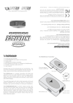
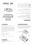
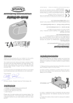
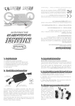
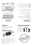
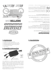
Instal the RADARnode according to the diagram above.
Please note that the RADARnode transmitter is not waterproof so should always be positioned in the seat cavity.
2.1
The Cheetah connector cable for the V1 must be
installed the correct way round. Each end of the cable is
labeled. If the cable is inserted the wrong way round it
will not work. Plug the end labelled “V1” into your Valentine
detector.
2.2 Safely route the Cheetah connector cable from your V1
to the cavity underneath the motorcycle seat. Secure the
cable to the bike wherever possible, avoiding contact with
any high temperature engine components or exhaust system.
2.3 Plug the RDI connector cable into the Cheetah V1
Remote Adapter, and then connect this to the DETECTOR
socket of the RADARnode transmitter.
2.4 Double check that the RDI software card and connector
cable are specific to your radar detector. The RDI software
card is pre-installed in the side of the RADARnode transmitter. Always ensure that the power is OFF before removing or inserting your RDI software card.
2.5 Connect the Cheetah V1 Remote Adapter to the Valentine direct wire power adapter. Then use the Accessory
socket of the direct wire adapter to connect up the Valentine
Concealed Display or the Valentine Remote Audio Adapter
(or both of them together.)
2.6 To power the system, connect the Valentine direct-wire
adapter to the POWERSENSEnode. The fuse pack can then
be connected directly to the battery terminals. RED is positive, BLACK is negative. There is no need to remove the
leads from the battery. Just loosen the nut on the clamp,
slide in the spade terminal, and re-tighten the nut.
2.7 OPTIONAL - laser jammer installations only. Connect
the small flying lead with the bullet connector to the similar
over-ride cable on the Cheetah LASERnode.
V1 menu items can be set according to personal preference.
POWERSENSEnode
In-line fuse with
battery connectors
4.1 Starting up your system
The radar detector and VizAlert display work independently.
The POWERnode attached to the battery will automatically
turn on the power to the RADARnode transmitter and radar
detector when you start your motorcycle’s engine. It will
remain on for as long as the engine is running.
The VizAlert’s battery pack has a sliding ON/OFF switch. All
6 LEDs will flash once, at the same time, to confirm it is
switched on. When you power up your detector, the transmitter will begin to transmit to the VizAlert helmet receiver. The
VizAlert LED's will flash in a circular sequence when the
wireless link has been established.
4.2 Testing your system
Press and release the test button on the side of the RADARnode. The VizAlert will flash each LED in sequence. Remember, your engine must be running for the transmitter and
detector to be powered up.
4.3 Alerts
Please refer to the VizAlert manual for interpreting alerts.
Ku band users in Europe - If Ku band is enabled, please
note the V1 uses the same audio tone for K and Ku bands.
The RADARnode will copy this and transmit a K band warning for both K and Ku alerts so the VizAlert will flash white for
both K and Ku bands.
4.4 Switching off your system.
When you switch off your engine, power to the RADARnode
transmitter and radar detector is automatically switched off.
The VizAlert is motion sensitive and switches off after 10
minutes of no movement.
The VizAlert V2’s battery pack has a sliding ON/OFF switch
and an automatic shut off, if you leave it on by accident.
Constant KU Band radar alert
RDI software card is not correctly installed. It must be fully
inserted into the slot on the side of the RADARnode. Switch
off power, then remove the card and re-insert flush. Always
ensure that the power is OFF before removing or inserting your RDI software card.