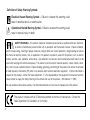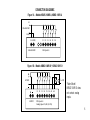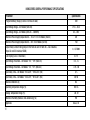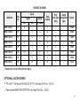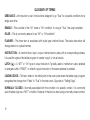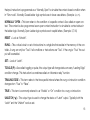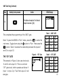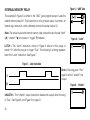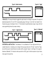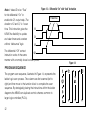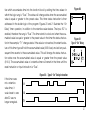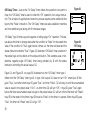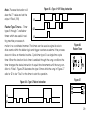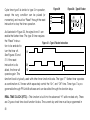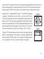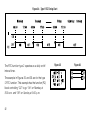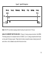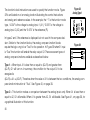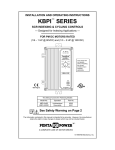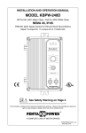
1
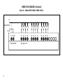
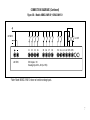
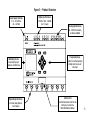
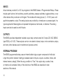
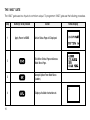
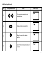
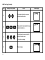
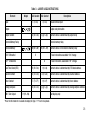
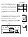
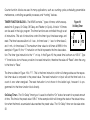
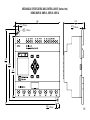
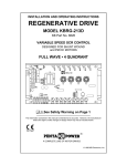
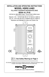
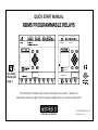
QUICK START MANUAL
KBMS PROGRAMMABLE RELAYS
L1 L2(N)
85~265 VAC
!
I1 I2 I3 I4 I5 I6
AC Input x 6
KBMS-10MR-A
P/N 16020
See Safety
Warning on
page 4
Relay Output x 4
The information contained in this manual is intended to be accurate. However, the
manufacturer retains the right to make changes in design which may not be included herein.
Automation and Control
© 2003 KB Electronics, Inc.
(See back cover)
Table of Contents
page
Introduction to the KBMS Programmable Relay . . . . . . . . . . . . . . . . . . . . . . . . . . . . . . . . . . . . . . . . . . . . . 8
Specifications . . . . . . . . . . . . . . . . . . . . . . . . . . . . . . . . . . . . . . . . . . . . . . . . . . . . . . . . . . . . . . . . . . . . . 10
Features by Model . . . . . . . . . . . . . . . . . . . . . . . . . . . . . . . . . . . . . . . . . . . . . . . . . . . . . . . . . . . . . . . . . . 11
Glossary of Terms . . . . . . . . . . . . . . . . . . . . . . . . . . . . . . . . . . . . . . . . . . . . . . . . . . . . . . . . . . . . . . . 12, 13
Inputs . . . . . . . . . . . . . . . . . . . . . . . . . . . . . . . . . . . . . . . . . . . . . . . . . . . . . . . . . . . . . . . . . . . . . . . . . . . 14
Outputs . . . . . . . . . . . . . . . . . . . . . . . . . . . . . . . . . . . . . . . . . . . . . . . . . . . . . . . . . . . . . . . . . . . . . . . . . . 14
Internal Program . . . . . . . . . . . . . . . . . . . . . . . . . . . . . . . . . . . . . . . . . . . . . . . . . . . . . . . . . . . . . . . . . . . 14
The “AND” Gate . . . . . . . . . . . . . . . . . . . . . . . . . . . . . . . . . . . . . . . . . . . . . . . . . . . . . . . . . . . . . . . . 16 - 19
The “OR” Gate . . . . . . . . . . . . . . . . . . . . . . . . . . . . . . . . . . . . . . . . . . . . . . . . . . . . . . . . . . . . . . . . . . . . . 19
Internal Memory Relay . . . . . . . . . . . . . . . . . . . . . . . . . . . . . . . . . . . . . . . . . . . . . . . . . . . . . . . . . . . . . . . 20
Latch Type . . . . . . . . . . . . . . . . . . . . . . . . . . . . . . . . . . . . . . . . . . . . . . . . . . . . . . . . . . . . . . . . . . . 20
Unlatch Type . . . . . . . . . . . . . . . . . . . . . . . . . . . . . . . . . . . . . . . . . . . . . . . . . . . . . . . . . . . . . . . . . 20
Toggling Type . . . . . . . . . . . . . . . . . . . . . . . . . . . . . . . . . . . . . . . . . . . . . . . . . . . . . . . . . . . . . . . . . 21
Differential Instruction . . . . . . . . . . . . . . . . . . . . . . . . . . . . . . . . . . . . . . . . . . . . . . . . . . . . . . . . . . . . . . . . 21
Program Sequence . . . . . . . . . . . . . . . . . . . . . . . . . . . . . . . . . . . . . . . . . . . . . . . . . . . . . . . . . . . . . . . . . 22
Ladder Logic Instruction Table . . . . . . . . . . . . . . . . . . . . . . . . . . . . . . . . . . . . . . . . . . . . . . . . . . . . . . . . . 23
ii
Function Blocks . . . . . . . . . . . . . . . . . . . . . . . . . . . . . . . . . . . . . . . . . . . . . . . . . . . . . . . . . . . . . . . . . . . . 24
Counters . . . . . . . . . . . . . . . . . . . . . . . . . . . . . . . . . . . . . . . . . . . . . . . . . . . . . . . . . . . . . . . . . . . . 24
Timer Function Blocks . . . . . . . . . . . . . . . . . . . . . . . . . . . . . . . . . . . . . . . . . . . . . . . . . . . . . . . . . . 26
On Delay Timers . . . . . . . . . . . . . . . . . . . . . . . . . . . . . . . . . . . . . . . . . . . . . . . . . . . . . . . . . . 26
Off Delay Timers . . . . . . . . . . . . . . . . . . . . . . . . . . . . . . . . . . . . . . . . . . . . . . . . . . . . . . . . . . 28
Flasher Type Timers . . . . . . . . . . . . . . . . . . . . . . . . . . . . . . . . . . . . . . . . . . . . . . . . . . . . . . . 29
Real Time Clocks . . . . . . . . . . . . . . . . . . . . . . . . . . . . . . . . . . . . . . . . . . . . . . . . . . . . . . . . . . . . . . 30
Analog Compare Blocks . . . . . . . . . . . . . . . . . . . . . . . . . . . . . . . . . . . . . . . . . . . . . . . . . . . . . . . . . 33
Text/HMI Relay . . . . . . . . . . . . . . . . . . . . . . . . . . . . . . . . . . . . . . . . . . . . . . . . . . . . . . . . . . . . . . . . 37
Tables
1. “AND” Gate . . . . . . . . . . . . . . . . . . . . . . . . . . . . . . . . . . . . . . . . . . . . . . . . . . . . . . . . . . . . . . . . . . . . . 19
2. “OR” Gate . . . . . . . . . . . . . . . . . . . . . . . . . . . . . . . . . . . . . . . . . . . . . . . . . . . . . . . . . . . . . . . . . . . . . . 19
3. Ladder Logic Instructions . . . . . . . . . . . . . . . . . . . . . . . . . . . . . . . . . . . . . . . . . . . . . . . . . . . . . . . . . . 23
4. Counter Types . . . . . . . . . . . . . . . . . . . . . . . . . . . . . . . . . . . . . . . . . . . . . . . . . . . . . . . . . . . . . . . . . . . 25
iii
Definition of Safety Warning Symbols:
Electrical Hazard Warning Symbol – Failure to observe this warning could
result in electrical shock or electrocution.
!
Operational Hazard Warning Symbol – Failure to observe this warning could
result in serious injury or death.
SAFETY WARNING – This product should be installed and serviced by a qualified technician, electrician,
or electrical maintenance person familiar with its operation and the hazards involved. Proper installation,
which includes wiring, mounting in proper enclosure, fusing or other over current protection, and grounding can reduce
the chance of electrical shocks, fires, or explosion in this product or products used with this product, such as electric
motors, switches, coils, solenoids, and/or relays. Eye protection must be worn and insulated adjustment tools must be
used when working with control under power. This product is constructed of materials (plastics, metals, carbon, silicon,
etc.) which may be a potential hazard. Proper shielding, grounding, and filtering of this product can reduce the emission
of radio frequency interference (RFI) which may adversely affect sensitive electronic equipment. If further information is
required on this product, contact the Sales Department. It is the responsibility of the equipment manufacturer and individual installer to supply this Safety Warning to the ultimate end user of this product. (SW effective 11/1992).
!
Be sure to follow all instructions carefully. Fire and/or electrocution can result due to improper use of this product.
This product complies with all CE directives pertinent at the time of manufacture. Contact the
Sales Department for Declaration of Conformity.
4
CONNECTION DIAGRAMS
Figure 1A – Models KBMS-10MR-A, KBMS-10HR-A
L1
85~265 VAC
L2(N)
L1 L2(N)
85~265 VAC
I1 I2 I3 I4 I5 I6
AC Input x 6
Figure 1B – Models KBMS-10MR-D*, KBMS-12HR-D
24 VDC
0~10V
I1 I2 I3 I4 I5 I6 A1 A2
24 VDC
*Note: Model
KBMS-10MR-D does
not contain analog
inputs.
DC Input x 6
Analog Input: A1, A2 (0~10V)
5
CONNECTION DIAGRAMS (Continued)
Figure 2A – Models KBMS-20MR-A, KBMS-20HR-A
L1
85~265 VAC
L2(N)
6
L1 L2(N)
I1 I2 I3 I4
85~265 VAC
AC Input x 12
I5 I6 I7 I8
I9 IA IB IC
CONNECTION DIAGRAMS (Continued)
Figure 2B – Models KBMS-20MR-D*, KBMS-20HR-D
24 VDC
0~10V
I1 I2 I3 I4
24 VDC
I5 I6 I7 I8
I9 IA A1 A2 OV1 OV2
DC Input x 10
Analog Input: A1, A2 (0~10V)
*Note: Model KBMS-20MR-D does not contain analog inputs.
7
INTRODUCTION TO THE KBMS PROGRAMMABLE RELAYS
The KBMS Series of Programmable Relays are designed for machine automation and process control applications. Several models are offered which provide a choice of input power (AC or DC), number of input/outputs (10, 12, and 20), and input type (digital DC or AC and 0 - 10 VDC analog). All
models contain high current independent output relays. In addition, “H” suffix models offer Real Time
Clock (RTC) operation and models KBMS-12HR-D and KBMS-20HR-D contain two analog inputs.
Simplified Ladder Logic Programming is accomplished with the front panel digital LCD keypad or
PR-Link™ Windows® 95/98/2K/XP PC software. Additional programming flexibility is achieved with
the optional EEPROM cartridge, which is used to download and upload programs from one KBMS to
another.
Although simpler in design, and low cost, the compact KBMS Series, with their expanded features,
can replace PLCs in many applications. Contains built-in DIN rail and slid-out tab panel mounting
systems. Barrier terminal blocks facilitate wiring.
8
Figure 3 – Product Overview
Power Supply Terminals
21.6 ~ 26.4 VDC or
85 ~ 264 VAC
Monitoring Screen
Screen Display Logic
Diagrams and I/O Status
Digital Output Terminals
8 A Power Relay Outputs
4 or 8 Outputs
Digital Input Terminals
24 VDC or 100 ~ 240 VAC
6 or 12 Inputs
Analog Input Terminals
0 ~ 10 VDC (2 Channels)
on Advanced Model
Programming Keys
Used for Local Programming,
Editing, Data Access and
Data Input
Interface Port
Used for Connection to the PR-Link
Software or to Insert the
MEM-PAK Memory Module
9
KBMS SERIES GENERAL PERFORMANCE SPECIFICATIONS
Parameter
Program Memory (Steps) (4 items x 80 lines of code)
Input Voltage Range – DC Models (Volts DC)
Input Voltage Range – AC Models (Volts AC – 50/60 Hz)
Specification
320
21.6 – 26.4
85 – 264
Maximum Power Supply Requirements – 10 & 12 I / O DC Models (mA DC)
80
Maximum Power Supply Requirements – 20 I / O DC Models (mA DC)
150
Output Relay Contact Rating (Amps @ 250 Volts AC and 24 Volts DC – non-inductive,
Amps AC and DC Inductive, NEMA)
LCD Display (Lines x Characters)
8,1.5, B300
4 x 12
Input Voltage Threshold – DC Models: “On”, “Off” (Volts DC)
>15, <5
Input Voltage Threshold – AC Models: “On”, “Off” (Volts AC)
>79, <40
Input Delay Time – DC Models: “On-to-Off”, “Off-to-On” (mS)
3, 5
Input Delay Time – AC Models: “On-to-Off”, “Off-to-On” (mS)
50, 50
Maximum Vibration (G)
0.5
Operating Temperature Range (ºC)
0 to 55
Storage Temperature Range (ºC)
-40, 70
Maximum Humidity (Relative, Non-condensing) (%)
Approvals
10
90
cULus, CE
FEATURES BY MODEL
Inputs
Model No.
Total
I/O
Digital
Analog
DC
AC
0 - 10 DC
Relay
Outputs
Real
Time Clock
(RTC)
Analog
Comparator
Types
Part No.
KBMS-10MR-D
10
6
—
—
4
—
—
16000
KBMS-10MR-A
10
—
6
—
4
—
—
16020
KBMS-10HR-D
10
—
6
—
4
2
—
16030
KBMS-12HR-D
12
6
—
2*
4
2
7
16035
KBMS-20MR-D
20
12
—
—
8
—
—
16040
KBMS-20HR-D
20
10
—
2*
8
2
7
16050
KBMS-20MR-A
20
—
12
—
8
—
—
16060
KBMS-20HR-A
20
—
12
—
8
2
—
16070
* Analog inputs can be used as discrete inputs.
OPTIONAL ACCESSORIES
• PR-Link™ Windows® 95/98/2K/XP PC Software (Part No. 16510)
• Removable MEM-PAK EEPROM Cartridge (Part No. 16500)
11
GLOSSARY OF TERMS
DEBOUNCE – An instruction or set of instructions designed to go “True” for a specific condition and a
single scan time.
ENABLE – This is similar to the “On” state or “On” condition. If a rung is “True”, the rung is enabled.
FALSE – This is commonly referred to as “Off” or “Off condition”.
FLASHER – This timer term is associated with cycle type function blocks. The status instruction will
change state in a cyclical manner.
INSTRUCTION – A function block, input, output, internal memory relay with a corresponding address.
It is used throughout the ladder program to create “rungs” or virtual circuits.
LATCH ( ) – A “SET” or “On” type of output instruction. Typically used to maintain an output enabled
or energized until a “RESET” or unlatch output instruction of the same address is enabled.
LEADING EDGE – This term refers to the initial point in the scan cycle where the ladder logic program
recognizes the change from “False” to “True” in the instruction. Opposite to “Trailing Edge”.
NORMALLY CLOSED – Normally associated with the condition of a specific contact. It is commonly
used in ladder logic as a “NOT” condition. Example, if the input is wired using a normally closed contact,
12
the input instruction is programmed as a “Normally Open” to simulate the contact closed condition when
in “Run mode”. Normally Closed ladder logic symbols are in lower case letters. (Example: i,c, m).
NORMALLY OPEN – This term refers to the condition of a specific contact. Also called an open contact. This contact is also programmed as an open contact instruction to simulate its contact status in
the ladder logic. Normally Open Ladder logic symbols are in capital letters. (Example: I,T, M).
RESET – Look at “Unlatch”.
RUNG – This a virtual circuit or set of instructions in a single line that resides in the memory of the controller. A rung can only be “True” if all conditions or instructions are “True”. If the rung is “True” the output will be enabled.
SET – Look at “Latch”.
TOGGLE (P) – Also called toggling or pulse, this output type will change status on every “Leading Edge”
condition change. This instruction is sometimes called an “alternator relay” function.
TRAILING EDGE – This term refers to the time specific interval where the rung or instruction condition
changes from “True” to “False”.
TRUE – This term is commonly referred to as “Enable” or “On” condition for a rung or instruction.
UNLATCH ( ) – This output type is used to change the status of “Latch” output. Typically both the
“Latch” and the “Unlatch” work as set.
13
INPUTS
Actual devices provide AC or DC input signals to the KBMS Series of Programmable Relays. These
include push buttons, limit switches, proximity switches, pressure switches, toggle switches, or any
other devices that provide an on/off signal. The models with analog inputs (0 ~10 VDC) use a voltage that represents a value. The analog inputs are provided by a transducer or process signal. In a
typical application these signals can represent temperature, fluid levels, or distance. The analog
inputs can also be used as on/off inputs.
OUTPUTS
The KBMS provides independent isolated output relay contacts rated for 8 amps 250 VAC (NEMA
type B300) or 24 VDC. These outputs can turn on solenoid valves, lamps, motor contactors, relays,
and many other devices used in machine and process control.
INTERNAL PROGRAM
The KBMS programmable relay uses an internal ladder logic program composed of individual
rungs that perform decision making processes based on inputs, outputs, counters, timers, and
internal memory relay(s). When the rung condition is “True”, the output relay, counter, timer,
or internal coil is enabled. Many of the functions of the KBMS are described in later
sections of this manual.
14
The KBMS Programmable Relays are easily programmed using the 8 buttons on the unit.
Select: Used to show the selection of available instructions types. Holding this button
for 3 seconds in the “Stop” mode will display all “H” Text/HMI displays. This feature is
only programmable with PR-Link Windows” based software.
OK: Use this button to accept the displayed selection of instruction and is also used
with the Main Menu Option.
Note: Press the “SEL” and “OK” simultaneously to insert a rung above the cursor position.
Escape: Used to exit the displayed screen. When in the ladder screen press the ESC
to display the main menu. If in a function block, the ladder screen will be displayed.
Delete: Used to delete an instruction or rung from the ladder program.
The 4 navigational buttons are used to move the cursor within the functions or
ladder program. Note: Toggle down to the RUN option on the main menu screen to
place the KBMS in the “Run” mode.
15
THE “AND” GATE
The “AND” gate uses two inputs to control an output. To program an “AND” gate use the following procedure.
Step
Button(s) to be pressed
1
Apply Power to KBMS
16
Action
Active Status Page will Displayed.
2
Exit Active Status Page and Access
Main Menu Page.
3
Accepts Option From Main Menu
(Ladder).
4
Displays Available Instruction set.
KBMS Display
“AND” Gate Rung (Continued)
Step
Button(s) to be pressed
Action
5
This moves the cursor to the next
Instruction Area.
6
Displays Available Instruction Set.
7
Moves the cursor to the address
position.
8
Use UP Arrow to change the address of
I1 to I2.
KBMS Display
17
“AND” Gate Rung (Continued)
Step
Button(s) to be pressed
Action
9
This action will place the cursor on
the Next Instruction Area.
10
Press select 3 times to obtain the rung
connect instruction (--).
11
This will place the cursor on the 4th
and last instruction area.
This must be an output.
12
18
Press to display.
KBMS Display
“AND” Gate Rung (Continued)
Step
Button(s) to be pressed
13
Action
KBMS Display
This Button Accepts the First Default
Output Instruction ( [Q1)
Table 1 – “AND” GATE
This completes the programming of the “AND” gate.
I1
Note: To place the KBMS in “Run” mode, press the
to enter the
main menu. Toggle down using the
button to “Run.” Then press the
button. Table 1 illustrates the relationship between the inputs I1
and I2 to output Q1.
THE “OR” GATE
This example, in Figure 4, also uses two inputs,
I1 and I2 and output Q1. This is a common
“OR” gate circuit, which operates as follows: If
(input 1 or input 2) is “True” then output Q1 will
energize.
Figure 4 – “OR” Gate
Off
On
Off
On
I2
Off
Off
On
On
Q1
Off
Off
Off
On
Table 2 – “OR” GATE
I1
Off
On
Off
On
I2
Off
Off
On
On
Q1
Off
On
On
On
19
Figure 5 – “AND” Gate
INTERNAL MEMORY RELAY
This example in Figure 5 is similar to the ”AND” gate program except it uses the
internal memory relay M1. This instruction is not a physical output, but rather an
internal logic instruction, which ultimately controls the actual output Q1.
Note: The actual output and internal memory relay instruction also include “latch”
( ), “unlatch” ( ) and pulse or “toggle” (P) features.
Figure 6 – “Latch”
LATCH – The “Latch” instruction, shown in Figure 6, allows for the output to
remain “On” after the rung is no longer “True”. The following is a timing representation the “Latch” instruction. See Figure 7.
Figure 7 – Latch Instruction
I1
Note: If the rung goes “True”
again it will not “unlatch” the
output.
_Q1
UNLATCH – The “Unlatch” output instruction disables the output when the rung
is “True”. See Figure 8, and Figure 9 on page 21.
20
Figure 8 – “Unlatch”
Figure 9 – Unlatch Instruction
Figure 10 – “Toggle”
I2
_Q1
TOGGLE (P) – This output instruction toggles the output based on a change of input state. The output will
alternate between the “On” and “Off” for every leading edge of the input. It can “latch” and “unlatch” from
the same rung logic. See Figures 10 and 11. This instruction may eliminate many rungs of logic; which will
save programming time and processor memory.
Figure 11 – Toggle Instruction
Figure 12 – “Differential”
I2
PQ1
DIFFERENTIAL INSTRUCTION – The differential “On” and differential “Off” are “single scan time” executable instructions. It activates upon a change in the rung logic and turns “Off” after 1 scan time. These
are commonly used to reset timers and counters within a program. Figure 12, and Figure 13 on page 22,
illustrate a differential “On” instruction when used with an “AND” gate. It limits the duration of input instructions equal to the scan time.
21
Note: It takes I2 to be “True”
for the differential “On” to
enable the Q1 output relay. The
duration of D and Q1 is 1 scan
time. This instruction gives the
KBMS the flexibility to update
and clear timers and counters
without “debounce” logic.
Figure 13 – Differential “On” with “And” Instruction
1 Scan Time
I1
D
I2
The differential “Off” contact
Q1
instruction works in the same
manner with a normally closed contact profile.
Figure 14
PROGRAM SEQUENCE
The program scan sequence, illustrated in Figure 14, represents the
ladder logic scan process. The columns are first scanned (left to
right) and then move to the function block to complete the scan
sequence. By strategically placing the instructions within the ladder
diagrams the KBMS can duplicate control schemes common to
larger logic controllers (PLC’s).
22
Table 3 – LADDER LOGIC INSTRUCTIONS
Element
Output
N.O. Contact N.C. Contact
I (I1~IC)
Input
i (i1~iC)
Output
Description
Actual terminal input
Output relay instruction
Output Contact
Q (Q1~Q8)
q (q1~q8)
Internal Memory Relay
Contact status is determined by output relay
Internal memory relay
Internal Memory
M (M1~MF)
“ON” Differential
D
“OFF” Differential
m (m1~mF)
Contact status is from internal memory relay
1 Scan instruction executable “On” change
d
1 Scan instruction, executable “Off” change
Real Time Clock (RTC)
R (R1~R8)
r (r1~r8)
Contact status is determined by RTC block address
Counter Contact
C (C1~C8)
c (c1~c8)
Contact status is determined by counter address
Contact status is determined by timer address
Timer Contact
T (T1~TF)
t (t1~tF)
Analog Compare
G (G1~G4)
g (g1~g4)
HMI / Text Output
H (H1~H8)
Contact status is determined by analog compare address
Text display only.
*Press the SEL button for 3 seconds to display the Type 1 “H” text in stop mode.
23
FUNCTION BLOCKS
The function blocks are programmed in the 4th area. They use an address instruction, which is then
used in the ladder program to control the status of the rungs. The function blocks can be accessed
directly from the Main Menu or when programmed into the ladder rung. After selecting the instruction, a function block will appear, which is to be configured as required.
COUNTERS – A total of 8 counters with 4 counter types can be used in the logic program. The counter functions as both an “Up” and a “Down” counter based on the status of the control instruction, or
input instruction (“I2” in Figure 15). The various counter types are shown in table 4, on page 25.
COUNTER FUNCTION BLOCK – In the example in Fig 15, the “1” on top of
Figure 15 – “Counter”
the function block represents the counter type. The accumulated value is
shown as “0002” and the preset as “0003”. The counter has a count resolution of 1 and a maximum count of 9999. Cascading is possible for higher
counts if required. In this example, “I3” is the reset instruction and it will set
the accumulated value to zero. “C1” is the counter number. The “C1” instruction changes status as the accumulated value is compared to the preset value. Counter types 3 and
4 are retentive, therefore will retain the count during a power loss condition. Counter types 2 and 4
are capable of count overflow, therefore the accumulated value can exceed the preset value.
24
Figure 16 illustrates an example of a typical non-retentive, no
overflow “Count up Instruction” set for a preset value of 3. The
Counter status instruction C1 then triggers the actual output Q1
when input I1 goes “True” and “False” 3 times (see Figure 18).
Note 1: The counter reset instruction I3 and direction instruction
I2, which are entered in the function block, are not shown in
Figure 18.
Table 4 – Counter Types
Counter
Number Type
Count
Overflow
Memory
Type
Counter 1
No
Non-Retentive
Counter 2
Yes
Non-Retentive
Counter 3
No
Retentive
Counter 4
Yes
Retentive
Figure 16
Note: In the initial main menu screen the user can enter the function block separately, however, changing the values in the counter are done through the ladder
programming menu selection by selecting the function block.
As illustrated in Figure 17, the reset input of I3 sets the counter’s accumulated
value back to zero. If I2 is enabled the counter will count down.
Figure 18
Figure 17 – Type 1 Counter Instruction
I1
C1
Count Value 3
Reset
I3
25
Counter function blocks are used in many applications, such as counting cycles, scheduling preventative
maintenance, controlling sequential processes, and “homing” devices.
TIMER FUNCTION BLOCK – The KBMS contains 7 types of timers, which are sepFigure 19
On Delay Timer
arated into 3 groups, On Delay, Off Delay, and Flasher (or Cycle). A total of 15 timers
can be used in the logic program. The timer functions are controlled through a set
of instructions. This set of instructions control the timer type, time base range, and
reset. The timer base resolution is 0.1 sec., for timer base 1, 1 sec. for timer base 2,
and 1 min., for timer base 3. The maximum timer value for all timers is 9999. In the
example in Figure 19, the “1” instruction on the left represents the time base selection. The timer type instruction is the “1” on top. In the Figure 19, the preset time is shown as “008.0”. Type
“1” timer blocks do not have a provision for a reset instruction, therefore the value will “Reset” when the rung
to the timer is “False”.
The timer address in Figure 19 is “T1”. This is the timer instruction, which will change status as the respective timer value is compared to the preset value. The reset instruction or input will set the timer back to a
count of zero when energized. The reset instruction is not shown in the ladder logic, however it is programmed into the timer function block directly.
On Delay Timer – The “On Delay” timer type 1 is used to offset the “On” state of an event for a preset amount
of time. This time is the preset value “008.0” in the example which will change the state of the status instruction when the timer’s accumulated value reaches the preset value. The “On Delay” timer can be value reten26
tive which accumulates time into the function block by adding the time values for
which the logic rung is “True”. The status will change state when the accumulated
value is equal or greater to the preset value. This timer status instruction is then
addressed in the ladder logic of the program. Figures 20 and 21 illustrate the “On
Delay” timer operation, in addition to the retentive value feature. The input “I2” is
enabled, therefore the rung is “True”. The timer starts its clock and when the accumulated value is equal or greater to the preset value in the timer the status instruction in the example, “T1” changes state. If the value is not reached, the retentive feature of this timer type will hold the accumulated value (005.6 sec) and add any subsequent time events to the accumulated value. This will change the status instruction state once the accumulated value is equal or greater than the preset value
(010.0). The accumulated value of a retentive timer will remain in the timer until the
reset instruction or input instruction is “True”.
Figure 20
Figure 21
Type 2 “On” Delay
Figure 22 – Type 2 “On” Delay Instruction
If the timer were
not a retentive
value timer, it
would reset to zero
after I2 was no
longer energized.
I1
I3
T1
27
Off Delay Timer – Just as the “On Delay” timer offsets the operation of an event or
input, the “Off Delay” timer is used to offset the “Off” operation of an output instruction. This is helpful in applications where the process requires some additional time
beyond the “False” instruction. The “Off Delay” timers are also available in retentive
and non-retentive types along with 3 time base ranges.
“Off Delay” type 3 timer supports negative or trailing edge “On” operation. This feature allows the timer to change state after the condition is “False” for the preset time
value. If the condition is “True” again before it times out, the timer will reset and the
status instruction remains “True”. Figure 23, illustrates “Off Delay” timer operation in
the ladder logic and its effects on the status instruction. This example uses a nonretentive, negative edge “Off Delay” timer being activated by I2 with the status
instruction controlling the actual output Q2.
Figure 23
Figure 24
“Off” Delay
Figure 24, and Figure 25, on page 29, illustrates how the “Off Delay” timer type 4
differs from the “Off Delay” timer type 3. In type 4 the output Q2 does not turn “On” when input I2 first
goes “True”, but rather when input I2 goes “True”, and then “False”. Q2 will stay on until the accumulated
value is equal to the preset value “010.0”, at which time Q2 will turn “Off”. If input I2 goes “True” again
before the timer accumulated value is equal to the preset value, Q2 will turn off and the timer will “Reset”.
Input I3 is the reset for the timer. Input I3 must be “False” for the timer to operate. When input I3 goes
“True”, the timer will “Reset” and Q2 will go “Off”.
28
Note: The reset instruction will
clear the T1 value and set the
output “False” (Off).
Figure 25 – Type 4 “Off” Delay Instruction
I2
Flasher Type Timers – Timer
Q2
types 5 through 7 are flasher
timers which are useful in setI3
ting machine processes in
motion in a coordinated manner. The timers can be used as signal clocks to
drive events within the ladder logic and trigger counters as alarms if the process
does not follow an intended routine. Cycle timer type 5 is a single time cycle
timer. When the function block timer is enabled through the rung conditions the
timer changes the status instruction in equal time increments until the rung condition is “False”. Figure 28 illustrates the type 5 timer while the rung in Figure 27
calls for I2 to be “True” for the timer to start its operation.
Figure 28 – Type 5 Flasher Instruction
Figure 26
Flasher Timer
Figure 27
I2
Q1
29
Cycle timer type 6 is similar to type 5 in operation,
except the rung condition can be pulsed (or
momentary) and must be “Reset” through the reset
instruction to stop the timer operation.
Figure 29
Figure 30 – Type 6 Flasher
As illustrated in Figure 29, the signal from I1 can
enable the flasher timer. The type 6 timer requires
the “Reset” instrucFigure 31 – Type 6 Flasher Instruction
tion to be enabled to
turn the timer off.
I1
See Figures 30 and
31. If the reset
Q1
instruction is disabled, the timer will
I3
operate again. This
function block is typically used with other timer function blocks. The type “7” flasher timer operates
as combination of 2 timers which separately control the “On”, and “Off” time. Timer type 7 is programmable through PR-Link® software and can be edited through the function keys.
REAL TIME CLOCK (RTC) – This function is built into the advanced “H” suffix models only. There
are 2 types of real time clock function blocks. The current day and time must be programmed in
30
order for the RTC to operate. The control time is programmed using the Real Time Clock option on
the main menu (press ESC to access the main menu). A total of 8 RTC functions can be used in
the logic program. The RTC can be used to control external outputs or internal memory relays.
In Figure 32, the “1” specifies the RTC as type “1”. The “MO-FR” are the days
of operation. The timers will turn on at 8:00 a.m. and turn off at 5:00 p.m.
(17:00) each day Monday thru Friday. In the example the current time is indicated as “15:59”. The rung must be programmed to enable the RTC function
block for the output instruction (R1~R8) to change state (see Figure 33). The
data entry uses for the days of the week, “Su, Mo, Tu, We, Th, Fr, Sa and Su”.
The hours and minutes are in the 24 hour format (eg. 15:59 = 3:59 p.m.).
Figure 32
Figure 33
The type 1 RTC timer functions as a time of day timer with a single “day skip”
feature. A typical application of this function is for energy management and
time driven events. The RTC needs a “True” condition in the ladder program
to run. An example or RTC type 1 is shown in Figure 34 on page 32.
31
Figure 34 – Type 1 RTC Timing Chart
ON
OFF
The RTC function type 2 operates as a daily on/off
interval timer.
The example in Figures 35 and 36 are for the type
2 RTC function. This example has the function (R2)
block controlling “Q2” to go “On” on Monday at
8:00 a.m. and “Off” on Sunday at 5:00 p.m.
32
Figure 35
Figure 36
Figure 37 – Type 2 RTC Timing Chart
ON
OFF
Note: The RTC has memory backup protection during AC power loss for 72 hours.
ANALOG COMPARE FUNCTION BLOCKS – There are 7 analog compare functions in the KBMS.
The analog input(s) to be compared must be 0-9.99VDC. Up to 4 analog compare function blocks
can be used in the logic program. These function blocks compare the values of analog inputs with
each other or with a reference value within the function block.
33
The function block instructions are used to specify the function mode. Figure
38 is an illustration of an analog function illustrating the control instructions
and analog and reference values. In the example, the “1” is the function mode
type, “4.00V” is the voltage to analog input 1 (A1), “3.00V” is the voltage to
analog input 2 (A2) and the “0.00V” is the reference (R).
In types 2 and 3 the reference is displayed but not used in the compare decision. Similar to the function blocks, the analog compare function blocks
require the logic rung to be “True” for its operation. In Figure 39 when I1 input
is “True” the function will enable the relay output Q1.There are seven types of
analog compare functions available as described below:
Figure 38
Analog Type 1
Figure 39
Type 1 – When input A1 is less than or equal to (A2+R) and greater than
(A2–R), G1 will turn on. In summary, the condition for the output G1 to be
energized is
(A2+R) ≥ A1 ≥ (A2–R). Therefore when the value of A1 is between the two conditions, the analog compare function instruction is “True”. See Figure 40, on page 35.
Type 2 – This function makes a comparison between the analog inputs only. When A1 is less than or
equal to A2, G1 will enable. When A1 is greater than A2, G1 will disable. See Figure 41, on page 35, for
a graphical illustration of this function.
34
Figure 40 – Type 1 Analog Compare Function
Figure 41 – Type 2 Analog Compare Function
35
Type 3 – This function is similar to type 2 except the inputs are reversed. When A2 is less than or
equal to A1, G1 will turn “On”. When A2 is greater than A1, G1 will turn “Off”. This function may be
used in conjunction with type 2 analog compare functions which can be used to signal out of range
conditions.
Type 4 – In this function when A1 is less than or equal to R, G1 will be “True”. When A1 is greater
than R, G1 will go “False”. The value of A2 is not referenced when using the type 4 analog compare
function block. The following illustration shows how this function block reacts to the variations in the
analog input. (See Figure 42).
Figure 42 – Type 4 Analog Compare Function
R
A1
G1 Output
36
Type 5 – This function is similar to the type 4 analog compare function except the output is enabled
when the signal is equal or above the reference level. When A1 is greater than or equal to R, G1 will
be “True”. When A1 less than R, G1will turn “False”.
Note: The next 2 analog compare function blocks behave similar to type 4 and 5 except they utilize
the A2 input channel as opposed to the A1. (A1 is not referenced in this function.)
Type 6 – In this function when A2 is less than or equal to R, G(X) will turn “True”. When A2 is greater
than R, G1 will turn “False”. (A1 is not referenced in this function.)
Type 7 – In this function when A2 is greater than or equal to R, G(X) will turn “True”. When A2 is less
than R, G1 will turn “False”. (A1 is not referenced in this function.)
TEXT/HMI “H” RELAYS – This feature of the KBMS can only be programmed with the optional PRLink software package. For information contact your local Genesis distributor or call 1-800-221-6570.
37
MECHANICAL SPECIFICATIONS AND CONTROL LAYOUT (Inches / mm)
KBMS-10MR-D, 10MR-A, 10HR-A, 12HR-D
2.83
72
0.27
(2 Places)
6.9
0.17
(2 Places)
∅
4.3
L1 L2(N)
85~265 VAC
I1 I2 I3 I4 I5 I6
AC Input x 6
4.33
110
3.89
99
3.54
90
KBMS-10MR-A
P/N 16020
Relay Output x 4
38
0.35
(2 Places)
9
2.24
57
0.19
(2 Places)
5.0
MECHANICAL SPECIFICATIONS AND CONTROL LAYOUT (Inches / mm)
KBMS-20MR-D, 20MR-A, 20HR-D, 20HR-A
0.27
(2 Places)
6.9
0.17
∅
(2 Places)
4.3
4.96
126
2.24
57
0.19
(2 Places)
5.0
4.33
110
3.89
99
3.54
90
0.35
(2 Places)
9
39
LIMITED WARRANTY
For a period of 18 months from the date of original purchase, KB Electronics, Inc. will repair or replace, without
charge, devices which our examination proves to be defective in material or workmanship. This warranty is valid
if the unit has not been tampered with by unauthorized persons, misused, abused, or improperly installed and
has been used in accordance with the instructions and/or ratings supplied. The foregoing is in lieu of any other
warranty or guarantee, expressed or implied. KB Electronics, Inc. is not responsible for any expense, including
installation and removal, inconvenience, or consequential damage, including injury to any person, caused by
items of our manufacture or sale. Some states do not allow certain exclusions or limitations found in this warranty and therefore they may not apply to you. In any event, the total liability of KB Electronics, Inc., under any
circumstance, shall not exceed the full purchase price of this product. (rev 2/2000)
COPYRIGHT © 2003 by KB ELECTRONICS, INC.
All rights reserved. In accordance with the United States Copyright Act of 1976, no part of this publication may
be reproduced in any form or by any means without permission in writing from KB Electronics, Inc. (8/22/02)
“KB” and “GENESIS” are registered trademarks of KB Electronics, Inc.
KB Electronics, Inc.
12095 NW 39th Street, Coral Springs, FL 33065-2516 • (954) 346-4900 • Fax (954) 346-3377
Outside Florida Call TOLL FREE (800) 221-6570 • E-mail – [email protected]
www.kbelectronics.com
(A98028) – Rev. A1 – 8/2003