1
CARNEGIE MELLON UNIVERSITY
Resource Management for CAD Frameworks
A DISSERTATION
SUBMITTED TO THE GRADUATE SCHOOL
IN PARTIAL FULFILLMENT OF THE REQUIREMENTS
for the degree of
DOCTOR OF PHILOSOPHY
in
Electrical Engineering
by
Thomas F. Cobourn
Carnegie Mellon University
Pittsburgh, Pennsylvania
May, 1992
Copyright (c) 1992 by Thomas F. Cobourn. All rights reserved.
ii
To my parents
iii
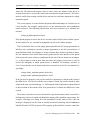
Abstract
We have devised an improved methodology for managing CAD resources -the tool and data abstractions that form the basis of tool integration efforts.
The methodology permits many different abstracted views to coexist within
the same CAD framework. This makes it easier to customize a CAD
framework for a view that captures the needs of local designers, yet populate
the same framework with CAD tools that have been encapsulated for other
views. A client/server based tool communication strategy and a novel user
interface management system, both operating in terms of abstracted tool and
data entities, further increase CAD tool portability and framework openness
in modern, distributed computing environments. The methodology also
provides the primitives to support advanced task management and design
process management systems.
iv
Acknowledgements
I am deeply indebted to my advisor, Professor Stephen Director, for his
support, guidance, and patience during this work. The most important things I
learned at CMU were from observing Professor Director in his roles as an
engineer, educator, businessman, and leader. I could not have chosen a better
mentor.
I would also like to thank the members of my thesis committee: Professor
Steven Fenves, Professor Wojtek Maly, and Dr. D.M.H. (Hank) Walker. Their
careful reading of the manuscript significantly improved this document, and
their feedback will be invaluable as I build on this work and present it to a
wider audience. Their efforts were greatly appreciated.
Two other individuals, Jay Brockman and Margarida Jacome, contributed
significantly to the development of the resource management concept. Their
technical and emotional support was crucial to my success.
Unfortunately I have been at CMU for so many years that generating a list
of all the people to whom I am grateful might keep me here for another year.
I hesitate to list even one name, for fear that it would diminish my appreciation
for the advice and friendship of the others. So to all I say, thanks!
Finally, I thank my parents for their love and encouragement, without
which this endeavor would not have been possible.
v
vi
Contents
1
2
3
4
Introduction................................................................................................................. 1
1.1 Tool Integration at the Resource Level................................................................ 2
1.2 Dissertation Outline ............................................................................................. 4
Resource Management: Issues and Techniques....................................................... 5
2.1 Issues.................................................................................................................... 5
2.1.1 Hosts, Tools, and Processes..................................................................... 6
2.1.2 Data Models and Data Schemata ............................................................. 8
2.1.3 Designers ................................................................................................. 9
2.2 Techniques ......................................................................................................... 10
2.2.1 System Level Software .......................................................................... 10
2.2.2 Data Representation............................................................................... 11
2.2.3 Tool Communication and Control ......................................................... 19
2.2.4 User Interface Management................................................................... 22
2.2.5 Standards Development ......................................................................... 25
A New Approach to Resource Management .......................................................... 31
3.1 Multi-Schema Design Environment .................................................................. 32
3.1.1 Centralized Communication, Not Storage, of Data ............................... 32
3.1.2 Single Data Model, Multiple Data Schemata ........................................ 34
3.1.3 Simple, Semantic Data Model ............................................................... 36
3.2 Data Model Based UI Management................................................................... 39
3.3 Client/Server Architecture ................................................................................. 42
3.3.1 Description............................................................................................. 43
3.3.2 Comparisons .......................................................................................... 49
3.4 Task Level Support............................................................................................ 51
3.4.1 Separation from the Task Level............................................................. 51
3.4.2 Task Visualization ................................................................................. 52
The Cyclops Resource Management System.......................................................... 55
4.1 Software Overview ............................................................................................ 55
4.2 Data Model ........................................................................................................ 57
4.2.1 Definition ............................................................................................... 57
4.2.2 Data Definition Language...................................................................... 61
4.3 Data Server ........................................................................................................ 61
4.3.1 Manipulating Frames ............................................................................. 62
4.3.2 Querying Frames and Classes................................................................ 64
4.3.3 Sending and Receiving Requests........................................................... 64
4.3.4 Schema Integration Tools ...................................................................... 68
4.4 User Interface Server ......................................................................................... 69
4.4.1 User Interface Operations ...................................................................... 69
4.4.2 User Interface Toolkit............................................................................ 70
4.4.3 User Interface Language ........................................................................ 73
4.4.4 Limitations ............................................................................................. 79
vii
4.5 Encapsulation Classes........................................................................................ 81
Examples.................................................................................................................... 83
5.1 Tool Encapsulation ............................................................................................ 83
5.1.1 Device Model Editor.............................................................................. 83
5.1.2 Circuit Simulator.................................................................................... 85
5.2 Schema Translation............................................................................................ 87
5.3 User Interface Generation .................................................................................. 88
5.3.1 A Circuit Simulator Front End............................................................... 88
5.3.2 A Primitive Task Manager..................................................................... 89
5.4 A Circuit/Fabrication Process Design Framework ............................................ 90
6 Conclusions................................................................................................................ 91
6.1 Summary ............................................................................................................ 91
6.2 Contributions ..................................................................................................... 92
6.2.1 Data Representation for Open Design Frameworks .............................. 93
6.2.2 Tool Communication for Distributed Systems ...................................... 95
6.2.3 User Interface Management for CAD.................................................... 95
6.2.4 Task Level and Design Process Level Support ..................................... 96
6.2.5 Software for a Resource Management System ...................................... 96
6.3 Future Work ....................................................................................................... 96
6.3.1 Data Representation ............................................................................... 97
6.3.2 Tool Communication ............................................................................. 98
6.3.3 User Interface Management................................................................... 99
A Cyclops Client Interface .........................................................................................101
B Cyclops Data Definition Language ........................................................................129
C device schema Description .....................................................................................132
D hspice schema Description .....................................................................................135
E cmu schema Description .........................................................................................149
F Cyclops User Interface Language .........................................................................155
Bibliography ...................................................................................................................169
5
viii
List of Figures
Figure 1.1
Figure 2.1
Figure 2.2
Figure 2.3
Figure 2.4
Figure 2.5
Figure 2.6
Figure 2.7
Figure 2.8
Figure 3.1
Figure 3.2
Figure 3.3
Figure 3.4
Figure 3.5
Figure 3.6
Figure 3.7
Figure 3.8
Figure 3.9
Figure 3.10
Figure 3.11
Figure 3.12
Figure 3.13
Figure 4.1
Figure 4.2
Figure 4.3
Figure 4.4
Figure 4.5
Figure 4.6
Figure 4.7
Figure 5.1
Figure 5.2
Figure 5.3
Figure 5.4
Figure 6.1
Odyssey CAD Framework Model ............................................................. 2
The Integrated Circuit CAD Environment................................................. 5
Data Model and Data Schema Example - Device Parameter Data............ 8
Levels and Views in Digital IC Design ................................................... 12
Approaches to the Data Representation Problem .................................... 12
Procedural Interface (PI).......................................................................... 15
ANSI/X3/SPARC Three-Schema Database Architecture ....................... 16
Seeheim User Interface Management System Model.............................. 23
CFI Framework Architecture................................................................... 26
Distributed Data Storage.......................................................................... 33
Single-Schema System Example ............................................................. 34
Multi-Schema System Example............................................................... 35
Multi-Schema System using Procedural Interfaces ................................. 36
Simple, Frame Based Data Model and Example Schema ....................... 37
Using Frames to Represent Relationships ............................................... 38
Example Schema Translation Operations................................................ 38
UIMS Example ........................................................................................ 40
Tools Communicating with the Data Server............................................ 43
Tools on Other Hosts ............................................................................... 45
Multi-Schema Architecture Example ...................................................... 46
User Interface Server Usage Modes ........................................................ 49
OCT/VEM/RPC Architecture.................................................................. 50
Cyclops Software Modules...................................................................... 55
Frame Classes and Instances.................................................................... 58
Derived Frame Classes ............................................................................ 59
Referencing by Superclass....................................................................... 59
Proposed FABRICS User Interface for Model Building .......................... 75
FABRICS Results Selector Created by User Interface Server ................. 79
Class Hierarchy for Encapsulation .......................................................... 82
Lott-Sutton CMOS Device Model Editor................................................ 84
HSPICE Device Model Selector.............................................................. 88
Primitive Task Manager........................................................................... 89
Circuit/Fabrication Process Design Framework ...................................... 90
A New Operating System for CAD Tools ............................................... 93
ix
x
List of Tables
Table 4.1
Cyclops Software Statistics ..................................................................... 57
xi
xii
Chapter 1
Introduction
Integrated circuit (IC) design has in the past been performed using CAD systems that can
be characterized as design environments [36]. These tightly integrated tool suites contain
CAD tools that were either developed to work with each other or patched together using
custom translators and glue software. Design environments perform well but tend to be
very fragile when modifications, such as the insertion of a new CAD tool, are necessary.
Recently, however, the quickening pace of advances in IC technology combined with
ever-shortening design cycles has caused designers to demand open systems in which they
can mix and match the best available CAD tools in a short amount of time. Development
of these new design systems, called design frameworks, has focused on the creation of
industry standards in software support [16][18][19] and information modeling
[22][20][50]. This approach has been, and remains, the most desirable means of easing the
tool integration burden. For example, if all CAD tool user interfaces are X Window System
based, it will be much easier to port tools between different host machines. Similarly if all
CAD tools use the same information model for circuit descriptions, it becomes much
simpler to share circuit design data between tools.
Unfortunately there is a large base of existing, independently developed tools that would
require much programming effort to modify for new standards. Furthermore, in the case of
information modeling, standards are especially difficult to develop since they must meet the
design data requirements of a large community of designers. Many such information
models are needed to span the breadth of IC design activity, and each is constantly in danger
of being made obsolete by changing technology. For these reasons, truly open frameworks
remain a dream rather than a reality.
We have devised an improved methodology for CAD framework tool integration that
relies less on standards by providing more support for managing the abstraction of data and
tools in a loosely coupled, heterogeneous design system. Observing that all tool integration
efforts use an abstracted view of data and tools as the common language for communicating
Resource Management for CAD Frameworks.... 1
Chapter 1: Introduction
Tool Integration at the Resource Level
designs and requests, our approach structures this communication and allows many
different abstracted views to coexist within the same design system. This promotes the
independent encapsulation of CAD tools, and allows tools to be more easily shared between
frameworks that are customized for the needs of local designers. Problems associated with
differences in software support in heterogeneous computing environments are resolved by
applying the client/server model of distributed computing [91]. The result is a framework
for design environments in addition to being a framework for design tools. This subtle
difference means that each CAD tool is permitted to view its portion of the design world as
it sees fit rather than according to an industry standard view.
1.1 Tool Integration at the Resource Level
CAD frameworks have traditionally been viewed as a collection of underlying facilities
needed to support tool developers, system integrators, and designers [29]. But this useroriented division of framework functionality often requires that aspects of tool, task, and
methodology level issues be addressed simultaneously, a condition that makes a design
system less flexible and harder to modify.
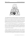
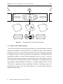
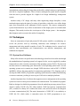
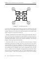
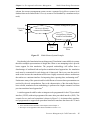
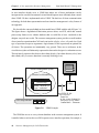
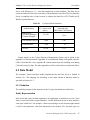
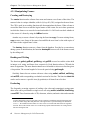
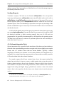
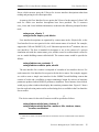
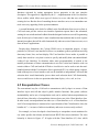
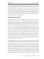
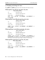
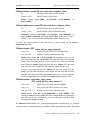
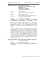
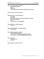
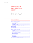
To deal more effectively with tool integration and other important issues such as task and
methodology management, the Odyssey CAD Framework project [48] has developed a
new framework model, shown in Figure 1.1, that consists of four levels of abstraction. Raw
tools and data reside at the component level, the level at which designers invoke tools
manually. Integrated design systems create a second layer, which we call the resource
level, for managing the components. Typically the resource level holds meta data, i.e.,
markers for tracking important design artifacts that physically reside at the component
level. The resource level can be thought of as containing the vocabulary of tool integration.
A CAD tool is considered integrated by virtue of its ability to communicate with the
framework in terms of resource level abstractions.
We propose a resource level that can semantically represent all component level
information of interest. A subset of entities at the resource level are made persistent and
used as meta data. Each CAD tool is responsible for creating meta data that advertises the
CAD functionality and locally stored (component level) data that the tool offers to make
available to other tools in the framework. For example, an encapsulated circuit simulator
might create time domain analysis and frequency domain analysis meta data items to
advertise its functionality; and netlist, device model, input stimulus, and analysis result
meta data items to advertise the contents of component level data files.
2 .... Resource Management for CAD Frameworks
Chapter 1: Introduction
Tool Integration at the Resource Level
specs
plans problems
alternatives
decisions
issues
Design Process Level
transient
analysis
netlist
ckt simulator
device model
Task Level
device model ckt simulator
name:
netlist
param1:
elements: param2:
Resource Level
CMU
FABRICS
Fab-level
Simulator
MetaSoftware
HSPICE
Component Level
Figure 1.1
Odyssey CAD Framework Model
The remaining resource level entities are not persistent. They are created on demand
when a request is received for the associated meta data entity. For example, when the circuit
simulator above receives a request for a persistent netlist entity, it will create non-persistent
resource level entities representing circuit elements and connections. These entities are
guaranteed to exist for as long as the requester is executing, but they are not stored
permanently at the resource level. Thus the resource level is used for the communication of
both tool control and design data between a heterogeneous collection of data sources.
We also advocate support for multiple abstractions, or views, of the design domain at the
resource level. This allows CAD tools, independently encapsulated for different resource
level views, to be more easily inserted into a new framework. A framework must still
choose one view definition as the common representation for communicating data between
tools, but that common view can be different for each framework installation -- customized
to suit the needs of the local designers.
Finally, we require that the resource management system be able to perform all
semantically meaningful operations requested on resource level entities regardless of
incompatibilities between the associated component level entities. This restriction permits
the creation of a task level that tracks dependency relationships between resources without
concern for how those resources physically exist in the framework. The task management
Resource Management for CAD Frameworks.... 3
Chapter 1: Introduction
Dissertation Outline
system used in Odyssey [42] unifies many of the features of CAD data, process, and
methodology management into a single, concise representation that significantly improves
designer productivity. As shown in Figure 1.1, the task level can in turn be used to support
a design process level that manages design methodology and planning activities [59]. At
this level, designers can concentrate exclusively on issues that concern the creative and
exploratory aspects of design, resulting in even greater gains in productivity.
1.2 Dissertation Outline
The remainder of this dissertation is organized as follows. Chapter 2 reviews the techniques
commonly used to organize integrated design systems, both design environments and
design frameworks. Chapter 3 introduces our new tool integration methodology, which
explicitly describes the resource level and structures it to serve as the foundation for higher
levels of design management and assistance. Chapter 4 describes the Cyclops Resource
Management System, an implementation of our ideas that provides resource level
management in a distributed design environment. In Chapter 5 we present several examples
of tool encapsulation and the use of Cyclops, including performance statistics. We conclude
in Chapter 6 by summarizing our contributions and outlining possible future work.
4 .... Resource Management for CAD Frameworks
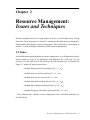
Chapter 2
Resource Management:
Issues and Techniques
Resource management involves a large number of diverse, yet intertwined, issues. To help
place these issues in perspective, Section 2.1 summarizes the characteristics of modern IC
design systems that pertain to resource management. This is followed by a description, in
Section 2.2, of the techniques commonly used for resource management.
2.1 Issues
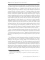
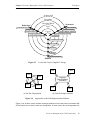
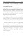
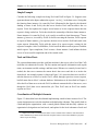
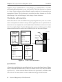
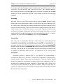
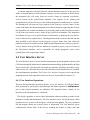
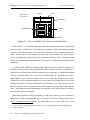
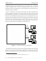
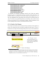
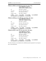
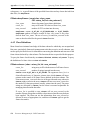
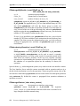
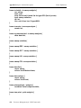
As an aid in discussing the problems of resource management, we will characterize today’s
design systems in terms of six dimensions: host platforms (H), CAD tools (T), tool
processes (P), data models (M), data schemata (S), and designers (D). As illustrated in
Figure 2.1, modern IC design systems have:
• multiple heterogeneous host platforms (Hi, i=1,...,nH)
• multiple tools on each host platform (Ti, i=1,...,nT)
• multiple processes for each tool (Pi, i=1,...,nP)
• multiple data models used by the tools (Mi, i=1,...,nM)
• multiple data schemata used by the tools (Si, i=1,...,nS)
• multiple designers with widely varying goals (Di, i=1,...,nD)
These characteristics, and the resource management issues associated with them, are
described below.
Resource Management for CAD Frameworks.... 5
Chapter 2: Resource Management: Issues and Techniques
Issues
Di
Hi
...
Ti
...
Mi
...
...
Figure 2.1
...
. . . Pi . . .
Si
...
...
...
The Integrated Circuit CAD Environment
2.1.1 Hosts, Tools, and Processes
Due to the decreasing cost and increasing performance of computer hardware, especially
engineering workstations, most design sites have switched from using a single mainframe
computer to relying on a network of personal machines. Typically a design group purchases
its equipment from one vendor, and possibly one product line, to minimize hardware
compatibility problems. An entire design organization, however, may use a variety of
hardware if design groups make their own purchasing decisions. One might also desire a
mix of hardware to satisfy performance needs; for example, some design groups need
supercomputers, high performance workstations, or parallel multiprocessors to execute
CPU-intensive engineering analysis applications. Hardware technology improves so
quickly that it is hard to stay with old technology for very long without suffering a
competitive disadvantage.
6 .... Resource Management for CAD Frameworks
Chapter 2: Resource Management: Issues and Techniques
Issues
Software environments exacerbate the problem.1 Two identical hardware units can have
very different support software installed: different operating systems, different compilers,
different graphics libraries, etc. It might also be the case that certain CAD tools are
available only on specific types of hardware. We refer to this combination of hardware and
software differences as platform heterogeneity. To minimize problems with software
portability, communication, and maintenance, one tries to populate a design system with a
collection of homogeneous platforms. But as design complexity has grown, so has the
number of design groups that are involved in each design project, making it more difficult
to enforce platform homogeneity in a large design organization. Furthermore increasing
design complexity requires more powerful CAD tools, which are often too difficult for a
design organization to develop themselves, so the tools must be acquired externally.
Established commercial tools are usually available for a variety of platforms, but early
versions of commercial tools and most research tools will only run reliably on their
development platforms. Add to this the sometimes staggered porting of generic software
such as word processing, project management, and CASE tools, and one can see why
design systems tend to be composed of multiple, heterogeneous platforms. Otherwise,
design organizations suffer the consequences of not having the best tools to do the job.
Figure 2.1 represents platform heterogeneity using the series of boxes labeled Hi. Most
platforms can execute several CAD tools simultaneously, represented by the ovals labeled
Ti. Each tool executes in its own process space2, though it may actually need more than one
process if it forks additional processes to accomplish its function, as shown by the circles
labeled Pi.
This combination of multiple heterogeneous platforms and multiple tools running in
separate process spaces on each platform has important implications for resource
management. The old practice of directly linking all of an environment’s tools into a
monolithic program will no longer work. The resource management system must provide
a way for tools to communicate data and requests across process and machine boundaries.
A formal methodology for communication and control must be developed to replace the
application-specific control mechanisms of monolithic tool suites. A strategy is needed to
manage the user interfaces of multiple, independently executing tools and redirect them to
the designer’s location in the network. And finally, the resource management system must
1. Ignoring, of course, recent efforts to standardize the operating system level and other critical
components of software environments.
2. A process space is a memory image of an application’s code and data, executable by the host
platform’s CPU.
Resource Management for CAD Frameworks.... 7
Chapter 2: Resource Management: Issues and Techniques
Issues
be implemented using as little platform-dependent code as possible to increase its chances
of being successfully used on a variety of platforms.
2.1.2 Data Models and Data Schemata
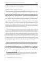
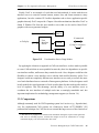
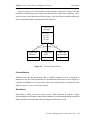
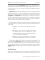
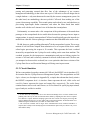
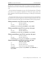
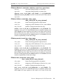
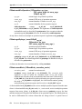
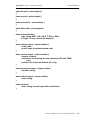
Before proceeding we must distinguish between a data model and a data schema. A data
model provides a set of concepts that can be used to structure a database, whereas a data
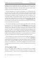
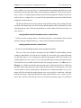
schema3 uses those concepts to describe a specific structure. For example, Figure 2.2a
shows the collection of concepts provided by a simplified entity-relationship data model
[75]. This data model describes information in terms of entity objects connected by relation
links. The entity can have any number of string-valued attributes. The relations can be 1to-1, 1-to-many, or many-to-many. Figure 2.2b shows a data schema designed to store
transistor device parameter information for a circuit designer. Figure 2.2c has a different
schema, designed for use by a process engineer who is interested in many more device
parameters. This example demonstrates how one data model can support many different
data schemata to describe the same body of information. We will refer to the combination
of a data model and a data schema as a data representation.
CAD tool developers can rarely choose any data model and any data schema for the tools
they create. The configuration of the local design system often dictates those choices. For
example, if the local design system is centered around a common database the developer is
forced to use the data model and data schema of that database. File-oriented design systems
allow more flexibility, but for reasons of software development and performance, a new
tool usually conforms to the data model and data schema of the tools it is used with.
Exceptions do occur, most often in research projects where the design domain is so new
that an appropriate model and/or schema does not exist. In most of these situations an
existing data model suffices, and a new schema or schema extension is developed.
Resource management problems stem from the fact that today’s design systems are
beginning to require CAD tools from a variety of outside sources. These sources each have
their own view of the design environment, one that captures the details of the data that they
find important in accomplishing their goals. This is depicted in Figure 2.1 by the clouds
labeled Mi, representing data models; and the ellipses labeled Si, representing the large
number of different schemata that can be created in a single data model. The challenge for
3. Note that the words model and schema are used very loosely in the literature, especially in fields
outside of database theory. Since the distinction is critical to our work, we consistently use the
terminology described above, taken from [77].
8 .... Resource Management for CAD Frameworks
Chapter 2: Resource Management: Issues and Techniques
entity
m
entity
relation
1
1
Issues
attribute-name: string-value
attribute-name: string-value
attribute-name: string-value
1
n
entity
relation
relation
n
entity
(a) Simplified Entity-Relationship Data Model
device
device
name: ----
name: ---type: ----
1
1
is-a
bjt-device
Is: ---Bf: ---Br: ----
1
1 is-a
mos-device
Vto: ---Kp: ---Gamma: ----
(b) Circuit Designer’s Data Schema
Figure 2.2
1
n
has-parameters
parameter
name: ---value: ----
(c) Process Engineer’s Data Schema
Data Model and Data Schema Example - Device Parameter Data
modern resource management systems is to find a way to coordinate the use of a large
number of diverse data representations in a single design environment.
2.1.3 Designers
The final dimension of modern design systems is that of the designer, represented by the
triangles labeled Di in Figure 2.1.4 Older design systems typically overlook this dimension
as it is assumed that designers manually invoke CAD tools and require no further
assistance. But today’s IC designers are faced with an overwhelming number of CAD tools,
each requiring some amount of arcane knowledge to operate. Organizing sequences of tools
to perform a complex task can involve even more arcane operating system level
4. The figure shows only one designer per host platform since most engineering workstations have
one display terminal. Note, however, that designers may invoke tools on any number of host
platforms.
Resource Management for CAD Frameworks.... 9
Chapter 2: Resource Management: Issues and Techniques
Techniques
manipulations, and tracking the design data produced by multiple attempts at performing a
task can be a logistical nightmare. Thus a resource management system must be designed
from the start to provide support for a higher level design methodology management
system.
Another reality of IC design, and many other engineering design disciplines, is that
modern designs require the input of a variety of specialists, each with a view of the design
space that corresponds to the subdomain of their expertise. The resource management
system should therefore try to allow customization of the design system to suit individual
designers. This mainly involves the visual aspects of the design system -- the metaphors
that designers need to reason in the midst of complexity.
2.2 Techniques
Since an enumeration of past and present ECAD systems would be overwhelming, we
review the previous work by describing commonly used techniques for resource
management and citing notable examples of each. The techniques involve system level
software, data representation, tool communication, user interface management, and
standards development.
2.2.1 System Level Software
Many of the advances in open framework technology to date have been achieved through
the standardization of operating system level support. In fact, services supplied by modern
frameworks are often viewed as extensions of the operating system [67][29]. The first such
tool that assists in constructing open frameworks is the operating system itself. Several
operating systems are in common use, though UNIX derivatives such as DEC’s ULTRIX
and IBM’s AIX are the most popular for engineering applications [76]. Ongoing work to
develop the IEEE POSIX [38] portable operating system interface standard should bring
even more consistency, making it easier to port CAD tools to multiple platforms.
Another important class of software that supports resource management at the operating
system level involves inter-process and network communication. Two methods are popular.
Both are designed to shield the programmer from the underlying message protocol layer,
which is usually TCP/IP [55]. The oldest method, UNIX inter-process communication
(IPC), consists of a library of C routines that create, read, and write sockets for datagram
or stream communication [88]. The main characteristic of UNIX IPC is its similarity to
UNIX file I/O, which makes it somewhat easier for UNIX programmers to use.
10 .... Resource Management for CAD Frameworks
Chapter 2: Resource Management: Issues and Techniques
Techniques
Unfortunately the library of routines is very primitive -- programming with IPC can be
time-consuming and requires expertise to do it correctly. The second method is the remote
procedure call (RPC) [55]. RPC allows a program to directly call procedures declared in
other programs, as if the other programs were directly linked to the caller. This approach is
at a higher level than IPC, and most implementations include mechanisms that
automatically convert data (e.g., byte swapping) between different machine architectures.
Many hardware vendors now provide RPC facilities for their machines, making RPC the
method of choice for creating networked applications.
Graphical user interfaces for open frameworks have benefited tremendously by the
computing community’s broad acceptance of the X Window System [85] and the Motif
User Interface Environment [70]. X, which provides a window based library of graphics
primitives, has become a de facto standard. Motif, which contains a set of interaction
devices called widgets, is quickly becoming just as popular as X, though it still faces
competition from other widget sets such as Open Look [74] from AT&T and SUN, Athena
[14] from MIT, and the object-oriented InterViews toolkit [58] from Stanford. Widget sets
are a critical support tool for user interface development because implementing an entire
user interface using only the X primitives requires a substantial amount of programming.
Widget sets speed the process by providing a pre-programmed set of commonly used visual
devices such as labels, buttons, menus, and text editors. If the widget set is constructed to
enforce a particular set of policies with regard to user interaction, two CAD tools can be
given a common look and feel merely by using the same widget set. This makes it easier for
a designer to switch from tool to tool when performing design, and speeds the learning
process when a new tool is introduced. Motif provides further conveniences, most notably,
a window manager for providing a uniform set of operations (e.g., moving and resizing) for
all windows on a designer’s display, and a user interface language and compiler that allows
a tool developer to write a textual description of a user interface that can be converted
automatically into C code.
2.2.2 Data Representation
Data representation techniques are essential to any resource management system. CAD
tools cannot be integrated unless they agree, at some level, on both the structure and
meaning of design data. As the authors of [29] note:
Resource Management for CAD Frameworks.... 11
Chapter 2: Resource Management: Issues and Techniques
Techniques
One of the most important issues in framework design is choosing a data
model and corresponding implementation that is adequate for describing all
of the information used by the design system and can be updated easily to
new design styles and technologies, while remaining efficient and robust
enough to meet the performance needs of engineering design.
Unfortunately data representation is also one of the most difficult issues in framework
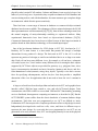
design. Much of the problem is due to the broad nature of IC design activities. To deal with
increasing complexity, designers use levels of design abstraction to hierarchically represent
IC designs. For digital IC design, the commonly used levels are architecture, algorithmic,
functional block, logic, circuit, and IC fabrication process. It is also generally recognized
that there are three distinct views of each level: behavioral, structural, and physical [68].
Figure 2.3, taken from [62], compactly displays these relationships (fabrication process
level excluded) and provides examples of the intersection of each level and view. As a
result the domain of digital IC design has been separated into many subdomains, each
having its own set of representations that best express the particular data of interest in that
subdomain while ignoring or summarizing the useful information in surrounding
subdomains.
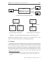
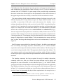
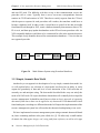
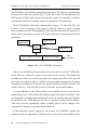
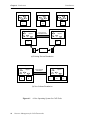
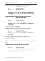
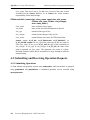
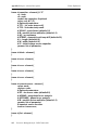
The earliest approach to solving the data representation problem involved writing
translators to and from the CAD tools to be integrated. This is depicted in Figure 2.4a (from
[29]), where each arrow symbolizes a unidirectional translator program. But as the number
of tools grew and representations evolved multiple versions to accommodate changes in
technology, the organization of Figure 2.4a became unmanageable. This spurred the
development of data exchange standards to transform an O(n2) proliferation of translators
to O(n), as shown in Figure 2.4b. Examples of such standards -- both officially sanctioned
and de facto -- include EDIF [6], VHDL [35], and Verilog [25] for hardware description;
CIF [13] and Magic [40] for layout; and PIF [90] for IC fabrication processes.
Most early CAD tools adopted the file based input/output behavior of C programs in a
UNIX environment [11]: executed programs read one or more input files and write one or
more output files. Eventually system integrators adopted conventional database technology
to store design data. This was a significant development not only because there was a large
quantity of information that needed to be reliably stored and accessed, but also because
engineering design is characterized by an abundance of relationships between design
entities [15]. Keeping all of this information in one place simplifies data management.
Use of a common storage facility for the data produced by all CAD tools in a design
environment thus became a popular technique for implementing the organization shown in
12 .... Resource Management for CAD Frameworks
Chapter 2: Resource Management: Issues and Techniques
Techniques
Architectural
Algorithmic
Functional Block
Structural
Behavioral
performance specs
algorithms
register transfers
boolean equations
electrical characteristics
Logic
CPU’s, memory
hardware modules
ALU’s, MUX’s, registers
gates, flip-flops, latches
transistors
Circuit
cell estimates, details
cell estimates
floorplans
clusters
physical partitions
Physical
Figure 2.3
Levels and Views in Digital IC Design
Tool
Tool
Tool
Tool
Tool
(a) Ad Hoc Organization
Figure 2.4
Tool
Common
Data Exchange
Standard
Tool
Tool
(b) Data Exchange Standard
Approaches to the Data Representation Problem
Figure 2.4b. In other words, the data exchange standard exists in the form of a database that
all tools must use to retrieve and store design data. In some sense, the most important role
Resource Management for CAD Frameworks.... 13
Chapter 2: Resource Management: Issues and Techniques
Techniques
played by today’s major ECAD vendors, Cadence and Mentor, is not as tool developers, but
rather, as system integrators. In particular, they are paid to maintain an ECAD database and
convert existing tools to work with that database. In return customers get a complete design
environment in which all tools operate seamlessly.
There has been a recent surge of interest in databases as commercial object-oriented
databases have become available. The advantages of object-oriented techniques for ECAD
data representation are well documented [96][27][56], most of these advantages stem from
the natural mapping of entity-relationship modeling to engineered artifacts. Many
experimental frameworks have been based on object-oriented databases [39][78].
Commercial frameworks have been slower to follow because of their large investment in
products based on older database technology or file-oriented input/output.
One of the best known databases for VLSI design is OCT [81], developed at U. C.
Berkeley. OCT’s main feature is a data model that permits the storage of multiple
abstractions for any portion of a design. The basic unit in OCT is the cell. A cell can
represent any portion of a design, as small as an individual device or as large as an entire
chip. Each cell can have many different views; for example, a cell can have a schematic
view and a layout view. Views can have many different facets for storing the basic objects
supported by OCT. Basic objects are provided for geometry (e.g., polygons, lines, wires,
layers), interconnection (terminals and nets), hierarchy (instances and facets), and freeform annotation of values (numeric, string, array, object). Typically a view has a contents
facet for specifying subcomponents, and an interface facet that provides a simplified
abstraction of the view for applications that do not need to know the view’s contents in
detail.
A large set of tools have been developed that read and write in OCT, and a graphical user
interface called VEM has been created to view and edit OCT-stored designs. Tools
communicate with VEM via RPC5 to access both VEM and OCT functionality, permitting
use in a distributed, heterogeneous computing environment, as described in [28]. But the
OCT/VEM/RPC system suffers from the classic drawbacks of common database design
environments. Tools that were not programmed to use OCT are difficult to insert.
Furthermore OCT does not provide a complete specification of how a chip design is stored.
Independently developed tools could use cells, views, and facets in different ways to
represent the same design. So even tools that were programmed to use OCT are not
guaranteed to be easily inserted. Also, OCT was designed primarily for use in the physical
5. Remote Procedure Call (see Section 2.2.1).
14 .... Resource Management for CAD Frameworks
Chapter 2: Resource Management: Issues and Techniques
Techniques
CAD subdomain. (Note the emphasis on storing geometry and connection information.) In
other subdomains, the restructuring of data necessary to use OCT may be unnatural or
awkward. Still, OCT/VEM/RPC is a good example of the powerful design environments
that can be created when all tools agree on the representation of data; and is indicative of
the approach upon which most of today’s commercial ECAD environments are based.
The major problem with the common database technique for design frameworks is the
difficulty in getting the IC design industry to agree on a single database standard. No one
can afford to convert their CAD tools to work with someone else’s database. A new
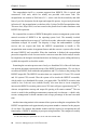
technique that addresses this issue is the procedural interface [2][8]. A procedural interface
consists of a set of operations for creating, manipulating, querying, and destroying design
objects. For example, the CAD Framework Initiative (CFI)6 demonstrated a procedural
interface that contained procedures such as cfiGetCellName and cfiPutPortNet [22][9].
Tools are categorized as object producers or consumers (or both). Producers service the Get
operations while consumers service the Put operations. Each operation is implemented as
a remote procedure call. The advantage of the procedural interface is that it does not require
storage of design data in a central database. Tools can maintain private storage of design
data, yet share that design data through direct tool-to-tool communication, as shown in
Figure 2.5.
But IC designers are not satisfied. As discussed in Chapter 1, the ability to mix and match
tools is becoming increasingly important. Unfortunately use of a common database
requires that tool developers be intimately familiar with the database. This discourages the
use of tools developed outside of the CAD organization that developed the database. The
same argument applies to the procedural interface technique, which will only work if all
tool developers agree to support the data representation on which the interface procedures
are based.
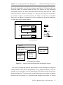
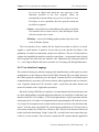
The database community has long recognized the need for multiple abstractions,
commonly called views, that give various user groups different ways to display and
manipulate the same information. In their influential report [7], the ANSI/X3/SPARC
group proposed a three-schema database architecture designed to separate user applications
from the physical database. One of the main characteristics of the architecture, illustrated
in Figure 2.6, is its support for multiple user views.The three-schema architecture shows an
internal schema for representing the physical data organization in the storage devices, a
6. The CFI is a consortium established in 1988 to develop guidelines for ECAD tools and
frameworks that will remove barriers to integration. See Section 2.2.5 for more details.
Resource Management for CAD Frameworks.... 15
Chapter 2: Resource Management: Issues and Techniques
Techniques
private
data
storage
private
data
storage
Tool
Tool
PI
PI
PI
PI
Tool
Tool
private
data
storage
private
data
storage
Figure 2.5
Procedural Interface (PI)
conceptual schema describing the entire enterprise of interest to a community of users, and
many external schemata that describe the conceptual data as seen by various application
programs. Typically a low level data model is used at the internal level and a high level data
model is used at the conceptual and external levels.
Eastman [15] identifies the need for multiple schemata in engineering design, where it is
typical for diverse groups of specialists with varying information needs to be involved in
the design of a single product. In [29] the same observation is made for ECAD using as an
example the mask designer’s focus on layout geometry relationships versus the logic
designer’s interest in gate types and connections.
As described earlier, OCT uses a data model that permits the storage of multiple
abstractions for any portion of a design. Note, however, that views in OCT are used as
organizational aids in managing the subdomains of ECAD depicted earlier in Figure 2.3.
They are typically not used to give tools different views of the same subdomain. For a tool
to be inserted in the OCT/VEM/RPC system, it must be programmed to make OCT RPC
calls (i.e., coded to use the OCT data model) and programmed to be in agreement with all
other tools in the system concerning how cells, views, facets, and attachments are used to
represent a design (i.e., coded to use a specific data schema). Of course tools can maintain
16 .... Resource Management for CAD Frameworks
Chapter 2: Resource Management: Issues and Techniques
Techniques
end users
External Level
Conceptual Level
External
Schema 1
...
External
Schema N
Conceptual Schema
Internal Schema
Internal Level
storage
Figure 2.6
ANSI/X3/SPARC Three-Schema Database Architecture
their own views of design by creating additional view objects, but there is no system
support for integrating views.
Unfortunately multi-schema database technology is not yet widely available. For
example, the commercial database Objectivity/DB [69] supports the distribution of data
across multiple databases residing on different host platforms; but all of the databases must
use a common data schema. Objectivity, Inc., has announced plans to introduce a multischema version by late 1992 [72], but it appears that the release will contain no special
support for coordinating the use of multiple schemata.
The bottleneck in implementing multi-schema databases is the problem of schema
integration -- the activity of creating a global, unified schema and the mechanisms for
mapping back and forth between it and the local schemata. The difficulties of schema
integration are well known [87][97][89]. To the best of our knowledge, the only existing
systems that attempt schema integration are research prototypes. (See [12] for a good
survey and review.)
An early project that developed a schema integration architecture was Multibase [46], a
system for integrating access to pre-existing, heterogeneous, distributed databases. The
main thrust of this work was to develop a single high level query language for all databases
Resource Management for CAD Frameworks.... 17
Chapter 2: Resource Management: Issues and Techniques
Techniques
in the system. The language was designed such that a query can be automatically split into
subqueries, each expressed in the local retrieval language of a particular database. The
results of the subqueries are then collected and integrated into an answer to the original
query. KADBASE [26], a CAD environment for structural engineering, incorporated
Multibase concepts to integrate expert systems with design databases. The problem with
the Multibase approach is that the global schema must be carefully constructed from the
local schemata. This would cause difficulties in an open design framework in which new
tools, bringing with them new local schemata, are inserted during the system’s lifetime.
Furthermore the Multibase and KADBASE prototypes were demonstrated using examples
in which the global schema is the concatenation of the local schemata. This may not always
be the case when dealing with independently developed tools, whose local data schemata
typically overlap.
In ECAD, Cadlab has proposed an adaptation of the ANSI/X3/SPARC architecture
called HIDE (High Level Database Language System) [33]. The conceptual level uses a
structural object-oriented data model, i.e., the objects lack methods, while application
views at the external level use a full object-oriented model. Support is provided for
automatically translating queries and updates between external schemata and the
conceptual schema. But as with Multibase, the permitted types of schema differences are
limited. In HIDE, an external view’s derivation from the global schema must involve only
subset, generalization, specialization, categorization, or extension relationships. It appears
that the tradeoff between multi-schema support and restrictions on inter-schema differences
is unavoidable.
In practice most of today’s ECAD design systems use a combination of common data
storage and ad hoc file/translator based approaches. Although several ongoing efforts are
aimed at leveraging object-oriented technology and practices as a CAD data panacea, it
remains to be seen whether one data representation can satisfy the needs of all IC designers.
In our opinion IC design will be best served by a heterogeneous collection of data storage
mechanisms combined with new integration techniques that manage the differences
between them. The authors of [84] also support this position:
While object-oriented systems and an extensible data model may provide
unifying structures for design data, we do not believe that the concept of a
single integrated design database supporting all design tasks or tools is
likely to come to fruition in the near future. A more appropriate goal may be
the realization of a well-integrated network of design databases developed
under standards evolving from efforts such as CFI and EIS.
18 .... Resource Management for CAD Frameworks
Chapter 2: Resource Management: Issues and Techniques
Techniques
2.2.3 Tool Communication and Control
Resource management systems must provide mechanisms for communicating both
design data and requests for data between CAD tools, and for controlling the execution of
tools. Much progress has been achieved in the area of tool communication and control, but
there remains room for improvement as commercial systems have been slow to adapt the
latest techniques in distributed computing,7 most notably interprocess communication and
client/server architectures.
A nearly universal technique that assists in tool communication and control is tool
encapsulation. The idea is to give each CAD tool a software wrapper that presents a
common programming interface to the framework at large such that all tools can be
controlled in a similar manner. Additionally encapsulation preserves the large investment a
design site has made in its existing tools, many of which are not available in source code
form if purchased commercially. For such tools, the encapsulation is a separate program
that acts as a watchdog process and translates control information from the framework into
a form that the tool is programmed to accept.
Another advantage of encapsulation is that it can be used to link a CAD tool to objects
in a graphical user interface for tool control8. This technique was first used in CMU’s
Cadweld [36] and EDA System’s Design Manager Server [32]. Typically each
encapsulated tool is represented visually by an icon. Through popup menus, buttons, or
other user interface components, the designer can set the command-line arguments of a tool
and initiate tool execution. Input and output files are also represented by icons, thus
providing the designer with a complete direct manipulation interface for controlling tools.
CAD system vendors have used encapsulation to allow the integration of so-called
foreign tools. Native tools, supplied by the system vendor, directly access framework
services (e.g., database and/or file management facilities), while foreign tools do so through
a special programming interface. Often, however, foreign tools do not have equal access to
the framework services available to native tools.
Unfortunately current encapsulation strategies are limited in scope. Typically an
encapsulation encodes a tool’s UNIX command-line arguments as well as the type of files
7. This hesitancy may be due in part to the intermingling of resource level tool control issues with
task level ones -- a situation avoided by the Odyssey framework model described in Chapter 1.
8. We describe user interfaces for tool control here instead of in Section 2.2.4 because they employ
well-established user interface practices. Their contribution is as a control mechanism rather than as
a new user interface technique for ECAD.
Resource Management for CAD Frameworks.... 19
Chapter 2: Resource Management: Issues and Techniques
Techniques
required for input and produced as output. In Cadweld, additional information was included
to characterize a tool in terms of factors such as speed and accuracy. In this form of
encapsulation, the surrounding framework performs well at controlling CAD tool
execution, but exhibits shortcomings in dealing with the communication of data since the
framework can only track data in terms of syntactically-correct files. The framework has
no knowledge of the semantic content of those files. For example, an encapsulated circuit
performance extractor that consumes time-domain analysis data in file format F1 will only
work in conjunction with circuit simulators that produce their analyses in F1 format, unless
special purpose translators are written and installed. This is why systems such as Cadweld
and DEC’s Powerframe [101] framework are solely meta data management systems. They
are not complete framework solutions.
The procedural interface described in Section 2.2.2 is a type of encapsulation that does
overcome these data communication problems, but at the expense of introducing unrealistic
demands on data representation services, as previously discussed. Yet its implementation
begins to answer a recently recognized need: communication between tools that exist in
their own processes, possibly across workstation boundaries. This is a prerequisite to
constructing the mixed-vendor environments that designers have been pleading for.
A procedural interface alone does not satisfy a framework’s inter-tool communication
needs. Operating systems provide communication primitives, but higher level facilities are
needed to support distributed engineering design environments. Several CAD
organizations, including ones at HP [60], Valid [99], Cadlab [100], the DoD’s DICE
concurrent engineering program [79], and most notably the CFI’s Inter-Tool
Communication (ITC) technical subcommittee [18], have proposed the use of a new
framework software module, called a message server, for coordinating the transfer of
control information between CAD tools.
The ITC-proposed message server uses an event handling paradigm closely modeled
after the X Window System. In X, programs contact a common window server and register
to be notified when events such as mouse movements, keyboard presses, and exposures
occur within windows they have created. The X server collects all events that occur on a
workstation and routes them to the appropriate client program depending on the current
context (i.e., which window the event has occurred in) and whether the window owner has
registered a handler routine for the event. Similarly, the ITC message server allows CAD
tools to register for framework events such as highlight net or simulate circuit. The message
20 .... Resource Management for CAD Frameworks
Chapter 2: Resource Management: Issues and Techniques
Techniques
context, however, is based on the designer name, the design project, the design object, and
the tool type.
Unfortunately framework message servers are still in the research stage. The CFI
continues to formulate specifications for a message server that will support all of the
communication scenarios that might be needed by CAD tools. But the idea of a message
brokering agent shows great promise as the core of a communication and control strategy
that permits CAD tools to be plugged in and out of a framework at will.
Another framework communication facility, one that must interface with the message
server, is the framework extension language. An extension language is an interpreted
computer language that both tools and designers can use to access framework functionality.
The most important characteristic of an extension language is that it be extensible. The
language must be able to incorporate new functions that are registered by the tools that
provide those functions.
Extension languages have been used in commercial frameworks for several years;
examples include Cadence’s Skill [95] and AutoCAD’s AutoLisp [66]. Most extension
languages are built on top of a standard computing language. For example, all of the above
examples are based on dialects of LISP. The CFI is proposing the use of Scheme as a base
language [23]. An extension language that is quickly gaining widespread attention is Tcl
[64]. Tcl provides a simple command language whose only data type is a string, a parser for
that language that is embedded in every tool as its argument handler, a collection of useful
utility functions, and a library of Tcl-wrapped user interface widgets called Tk [65] that can
be invoked just as any other tool in the system. Tcl has won many converts in the computing
community because of its simplicity and ease of use, but has yet to prove itself in the CAD
domain beyond its use as a tool control mechanism.9
The power of an extension language is that it gives users a measure of flexibility in
tailoring a design system for a site’s design methodology and culture as well as the work
routines and preferences of individual designers. Extension languages are thus relied upon
to help increase the lifetime of a design system. One disadvantage of extension language
availability is that the design system quickly becomes populated with a large number of
extension language shell scripts or macros for performing design tasks. When the system
9. The problem with Tcl for CAD concerns its use as a communicator of design data. For example,
SKILL supports eight different primitive types, including a database object type; whereas Tcl
supports only strings. But due to the flexibility of Tcl/Tk and the enthusiasm of its proponents, it
remains to be seen whether this shortcoming might eventually be resolved.
Resource Management for CAD Frameworks.... 21
Chapter 2: Resource Management: Issues and Techniques
Techniques
needs to be reconfigured in some way, it is usually difficult to find and update the shell
scripts that are affected by the change. Yet, one cannot deny the popularity of approaches
that put framework programmability into the hands of designers and system integrators.
2.2.4 User Interface Management
Since the introduction of high resolution, bit-mapped display hardware, graphical user
interfaces (GUI’s) have become a cornerstone of today’s ECAD systems. There is no
question that a good GUI improves designer productivity in highly interactive tasks such
as layout, routing, and schematic drawing [92]. Unfortunately, due to historical
circumstances similar to those faced in the data representation area, user interfaces for CAD
were initially an impediment to the development of open frameworks because the graphics
software of most tools were incompatible. A tool created for one design environment could
often not be run in another environment solely because the second environment used a
different window system or graphics library than the first.
GUI incompatibility is a problem that affects the entire software industry, not just the
computer-aided engineering sector. Generic software vendors sell primarily stand-alone
products, so shareable data representation is not as critical an issue as it is for CAD software
vendors. The user interface, on the other hand, is a major issue for everyone because
software products are more profitable if they can run on multiple hardware platforms.
Without GUI standards, a different version of the user interface portion of a software
product must be written for the native graphics environment of each platform.
This motivated the formation of several groups that set out to devise hardware
independent user interface standards. (These groups will be discussed in Section 2.2.5.)
Two of the results from their efforts have had a significant impact on ECAD. The first is the
X Window System [85], a server that manages a computer display’s graphics output and
mouse/keyboard input in terms of rectangular windows in which client applications
perform drawing operations (e.g., line/text drawing, and color/pattern filling) and sense
user events. The second is the OSF/Motif user interface environment [5]. Motif provides,
among other things, a collection of user interface components such as menus, buttons, and
scrollbars. Wide acceptance of the X Window System and Motif among ECAD tool and
system developers has resulted in greater software portability and user interface
consistency in recent CAD tools.
Thus user interfaces for open frameworks is seemingly a closed issue. Some advocate
that further improvement in consistency is needed, as evidenced by the fact that Motif also
22 .... Resource Management for CAD Frameworks
Chapter 2: Resource Management: Issues and Techniques
Techniques
supplies programmers with a style guide that specifies the preferred behavior for the
widgets in their toolkit. But for the most part designers can now switch between the CAD
tools produced by different vendors and experience a consistent look and feel.
In our opinion, however, consistent look and feel solves only part of the problem.
Certainly the use of common interaction styles among tools increases designer productivity
and shortens learning curves. But equally important goals concern new software
architectures for user interface implementation. Specifically, greater separation of CAD
tools from their user interfaces would make CAD software easier to develop, modify, and
port. This has been recognized by the computer science community, and is the main
objective of user interface management system (UIMS) research [98].
A UIMS is a tool that helps programmers create and manage the user interfaces for their
application programs. A UIMS makes user interfaces easier to develop and modify by
enforcing a separation of the user interface portion of a piece of software from its core
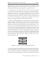
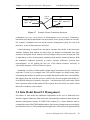
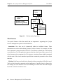
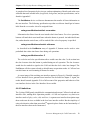
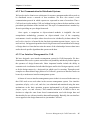
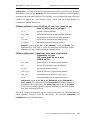
functionality. A popular UIMS model is the Seeheim model [53], shown in Figure 2.7. The
application layer is where presentation-independent code resides. The presentation layer
is typically a toolkit of widgets that control interaction with the end user. Finally, the dialog
layer expresses the presentation-dependent part of an application, usually via a user
interface definition language, in terms of how application layer requests are mapped into
user interface component behavior. UIMS’s are classified by their handling of the dialog
layer [10], that is, how the programmer specifies what the user interface should look like.
Successful approaches include event-driven, declarative, interactive layout, objectoriented, and data-driven [83].
Application Layer
Dialog Layer
Presentation Layer
Figure 2.7
Seeheim User Interface Management System Model
Most of the advantages that a UIMS holds for generic software applies to CAD software
as well. Since application code can express its user interface needs in very high level terms,
CAD tool developers can concentrate on CAD algorithms rather than manipulating buttons
and scrollbars. The increased separation also makes it easier to employ time-saving user
Resource Management for CAD Frameworks.... 23
Chapter 2: Resource Management: Issues and Techniques
Techniques
interface construction facilities to create the user interface portion of a tool since there are
fewer linkages from the user interface code back into the algorithm code. Portability is
improved because an application is not tied to a specific user interface technology. Note that
although most ECAD vendors have agreed to support OSF/Motif, popular versions of
advanced non-CAD applications useful to designers (e.g., symbolic computation,
information services, etc.) use Open Look [74]. Separation of a tool from its user interface
makes it easier to develop tools that will function under any GUI facility. Furthermore,
designers would be free to choose a UI technology that suits their personal preferences; a
design site would not have to choose between Motif and Open Look -- they could have
both. Eventually a UIMS may also support adaptable user interfaces, as described in [30],
that permit a user to switch dialog modes in the middle of a command. This directly
addresses the difficulty in creating a CAD tool user interface that is appropriate for both the
novice designer and the experienced designer. One can imagine expert designers changing
dialog modes to switch from a hierarchical menu system to a terse command line input, or
to access advanced CAD tool functionality that is beyond the comprehension of novices.
There is an additional problem unique to ECAD applications that maps well into a UIMS
solution. Due to the broadness of the domain, ECAD tools are beginning to be used to serve
more than one design function. For example a circuit simulator may be used directly by a
designer to produce circuit analyses, or it may used by an automated program that creates
regression models [71]. A partitioning tool can be used to place cells on a chip to minimize
the amount of wiring between cells, or it can be applied to clustering design variables based
on their statistical correlation [49]. It would therefore be very advantageous to have a
software architecture that allows you to easily switch a CAD tool’s user interface
depending on the task being performed. In the circuit simulator example, the highly
interactive session with the designer could be visualized using a large control panel for
setting observation points and invoking post-processing algorithms; while use of the
simulator by the regression modeler could appear merely as a message in a diagnostic
window like “simulation #37 completed”.
Unfortunately there are very few UIMS systems for CAD reported in the literature. The
only one we are aware of is ROSE/CHIDE [54], a research prototype developed at
Rensselaer Polytechnic Institute. ROSE is a database system for interactive engineering
applications that attempts to combine the best features of object-oriented and relational
databases. CHIDE lets programmers create user interfaces by editing forms and picking
menus on a graphics display, and then uses ROSE to store objects that describe those user
interfaces. The advantage of implementing the UIMS as an application of the database
24 .... Resource Management for CAD Frameworks
Chapter 2: Resource Management: Issues and Techniques
Techniques
system is that data collected from users or intended for display to users is stored in the same
repository as normal tool data. This makes it easier to share data between the active entities
in today’s complex engineering design environments. Note that this is an example of the
data-driven dialog layer approach, which has been used in generic UIMS’s such as Serpent
[51] and the George Washington UIMS [45].
The sparsity of UIMS’s for CAD is not without cause. There are doubts as to whether
current UIMS technology can support direct manipulation interfaces that are rich in
feedback [41], which is the case for key ECAD tools like layout editors and schematic
capture software. For example, the developer of a layout editor needs direct access to the
underlying window system to create an efficient CAD tool. But a UIMS imposes an extra
software layer that restricts communication between the editor’s layout database and layout
visualization. The UIMS inevitably decreases the layout editor’s user response time, and
most likely makes programming more difficult. We believe that more work in ECAD”smart” user interface components at the UIMS presentation layer is needed to help
alleviate problems associated with highly interactive tools.
Another drawback of current UIMS technology is that there is no standard dialog layer
language. The UIMS community continues to debate the merits of various dialog
techniques, and has yet to agree on exactly where the boundary between application and
user interface should lie. The portability benefits of the UIMS paradigm cannot be realized
until there is a dialog layer standard that all user interface technology developers are willing
to support. Also, most UIMS packages require that data communicated between an
application and its user interface be translated from the tool’s data structures into data
structures acceptable to the UIMS. This introduces additional overhead that tool developers
are reluctant to accept, especially with regard to existing tools. In our opinion, new UIMS
techniques that provide flexible boundaries between application and user interface, such as
the Slinky UIMS model proposed in [24], are needed to provide better support for ECAD
applications.
2.2.5 Standards Development
The importance of industry standards in each of the previous categories of resource level
techniques is unquestionable. Accordingly standardization in and of itself is perhaps the
most useful resource management technique of all. Indeed, in many circles the word
framework is synonymous with standards development. This section briefly examines the
major standardization efforts that are influencing CAD resource management.
Resource Management for CAD Frameworks.... 25
Chapter 2: Resource Management: Issues and Techniques
Techniques
The premier organization for ECAD framework activity is the CAD Framework
Initiative (CFI). The CFI was formed in 1988 as an independent industry effort to promote
standardization of CAD tool interfaces and their software environments [4]. The CFI
charter is to gain a consensus from industry users, the academic community, and vendors,
to develop guidelines for an industry-acceptable CAD framework implementation. The CFI
contains seven technical subcommittees (TSC’s):10 Architecture, Systems Environment,
Design Data Management, Design Methodology Management, Design Representation,
Inter-Tool Communication, and User Interface [17]. Each subcommittee is responsible for
generating proposals for standards in their area of expertise. These proposals go through a
series of reviews and modifications until they are finally distributed to the CFI membership
for comments and a corporate vote. Rather than creating entirely new standards, the CFI
has to date encouraged the adoption of existing standards in electronic CAD, engineering
CAD, and computing, as well as links to other standards bodies.
The CFI framework model currently proposed by the Architecture TSC [16] is shown in
Figure 2.8. Since the CFI model does not distinguish resource and task issues in the same
manner as the Odyssey framework model does, it comes as no surprise that several CFI
subcommittees are dealing with resource level issues. The Design Representation TSC is
working to develop a procedural interface for ECAD data [22]. As their goal concerns
solely the communication of design data, this group is firmly seated in the resource level.
Other groups, however, straddle the resource and task levels. The Design Data
Management TSC is chartered to develop procedural interfaces for meta data
representation and storage management [20]. This subcommittee deals with the resource
level issue of storing meta data, but also covers task level issues such as versioning,
aggregation (i.e., collections), and concurrent access to data. Likewise the Design
Methodology Management TSC is targeting the task level issue of controlling sequences of
tools, either for an individual designer or an entire design project. But their responsibilities
also include the resource level issue of tool invocation, which is why the Design
Methodology Management TSC is working on the CFI’s tool encapsulation specification
[21].
10. During the final preparation of this document, we received news that the CFI had restructured
the organization of its technical groups. There are now three Technical Committees (TC’s):
Computing Environment Services, Domain Independent Services, and Design Information. Each TC
contains from seven to ten Working Groups (WG’s), each of which is tackling an issue that was
formerly the responsibility of one of the original seven TSC’s. The issues are the same -- they have
just been re-organized to better distinguish platform-independent system-level issues, generic
application service issues, and domain-specific application service issues. See [86] for details.
26 .... Resource Management for CAD Frameworks
Chapter 2: Resource Management: Issues and Techniques
Techniques
User-Built Methodologies
Tool
Tool
...
Tool
Framework
Methodology Management
Design
Representation
Data Storage
Management
UIMS
UI
Toolkit
Meta-Kernel
Extension Language
Portability Services
(network and system level)
Figure 2.8
Kernel
(messages, events,
tool registration)
CFI Framework Architecture
Two of the three remaining CFI TSC’s are concerned with software environment issues.
The User Interface TSC must choose a graphical window system and a user interface
toolkit. Its recommendation [19] of the X Window System and OSF Motif toolkit and style
guide are close to receiving approval. Although Figure 2.8 shows a UIMS module, the User
Interface TSC has not yet published any documents describing it other than recommending
a base widget set. Given similar responsibility for choosing O/S level components, the
Systems Environment TSC has formulated recommended POSIX compliant operating
systems and use of an ANSI-C compiler. The final TSC, Inter-Tool Communication, is
responsible for the arrows in Figure 2.8; that is, this TSC is specifying a message
procedural interface, message dictionary, and message server that will enable the various
CFI modules to talk with each other.
Resource Management for CAD Frameworks.... 27
Chapter 2: Resource Management: Issues and Techniques
Techniques
Another organization that is beginning to have an impact on resource level issues for
open frameworks is the DARPA Initiative in Concurrent Engineering (DICE) [3]. DICE’s
mission is to develop, integrate, and disseminate technologies for concurrent engineering.
The goal of DICE is different from that of CAD. Rather than concentrating on techniques
for automating design, DICE is more concerned with giving people who work in large,
scattered organizations more freedom of interaction and information exchange. To improve
concurrent engineering, however, one first needs a good CAD framework. DICE’s
framework-related efforts have occurred primarily at West Virginia University’s
Concurrent Engineering Research Center (CERC), which has been leading industrial
laboratories and universities in developing generic services for concurrent engineering; and
General Electric’s Corporate R&D Center, which has been developing techniques for
integrating engineering tools with DICE services. Resource level topics being investigated
include transparent collocation of programs,11 shared access to data, and tool
encapsulation.
The program of broadest scope is the Department of Defense’s Engineering Information
System (EIS) project [34]. The goal is to develop standards for and prototypes of a generic
engineering information management system. The EIS program is divided into eight parts,
many of which provide resource level framework support. The Modeling Method and
Language defines the basic concepts of object, function, and type; and defines a language,
OODL (Object-Oriented Data Language), to describe information models in terms of these
concepts. The Engineering Information Model, expressed in OODL, gives structure and
semantics to EIS-managed information. Initial prototypes of the Engineering Information
Model will emphasize electronic engineering, though it will eventually be extended into
other domains such as mechanical and software engineering. The Object Management
System registers and tracks the vast number of objects in the system, and has the difficult
job of decomposing user requests into steps that can be distributed across multiple
databases and machines. This job is made easier, however, by the Database and File System
Adapters that translate object-oriented expressions into the query, update, and data
definition languages accepted by the diverse database management and file systems that
may reside in the EIS. Similarly, the Tool and Data Exchange Adapters are encapsulations
that allow EIS users to attach their existing tools to an EIS. The final parts of the program
are the User Interface Management System, for encouraging consistent user interfaces that
are separated from their tools; the Service Lattice, for tailoring EIS services to support local
11. That is, making resources available over a distributed design environment. With collocation, a
user on any workstation can easily run programs residing on any other workstation.
28 .... Resource Management for CAD Frameworks
Chapter 2: Resource Management: Issues and Techniques
Techniques
task and design process level policies concerning configuration management, version
control, audit trails, etc.; and Portability Services, essentially a virtual interface between an
EIS and its operating system that promotes portability of EIS’s between different operating
systems. EIS has many of the same goals and approaches as the CFI, but has to our
knowledge demonstrated no working prototypes.
The standardization groups described above enjoy substantial corporate involvement in
their activities. With designers demanding to be freed from design systems that lock them
into specific suites of tools, even the system integration vendors have something to gain
from establishing standards that can make open frameworks a reality. Academic
involvement in framework standardization is somewhat less, probably because the
standards groups place greater emphasis on achieving compromises that will keep all
participants satisfied rather than on striking out to discover new approaches. This is
understandable given industry’s shorter term outlook on new technologies. Standards will
certainly contribute significantly to achieving the open framework vision, especially when
the standardization concerns operating system functions and software support tools. But a
completely standards-based solution makes the unrealistic assumption that the design
community can be made homogeneous for an extended period of time. Realistically,
standards that concern design data will always have the same weakness -- obsolescence.
Recent work has the potential, however, to get off the standardization treadmill. Many
CAD framework projects, including those sponsored by all the standardization groups
described above, have been using or developing data modeling languages. This is a key
difference from past efforts because standardization is occurring at a meta level; that is, the
language for describing the data exchange standard is itself being standardized. This insight
has important significance in the ideas presented in Chapter 3. We will argue that the best
approach to creating open frameworks is to standardize the data modeling language only,
and to provide better mechanisms for supporting multiple descriptions of the data (i.e.,
multiple data schemata).
Resource Management for CAD Frameworks.... 29
Chapter 2: Resource Management: Issues and Techniques
30 .... Resource Management for CAD Frameworks
Techniques
Chapter 3
A New Approach to
Resource Management
A recurring theme of Chapter 2 is the trade-off between homogeneity and heterogeneity in
CAD frameworks. Homogeneity, achieved via standardization, continues to be the method
of choice for creating open frameworks. But this approach ignores the reality that standards
are slow to develop and quick to become obsolete in a domain as broad and rapidly
changing as integrated circuit design. On the other hand, heterogeneous environments are
notoriously difficult to manage.
In this chapter we present a new approach to resource management for CAD frameworks
that attempts to strike a balance between the homogeneous and heterogeneous approaches
of the past. The inadequacy of standardization in the area of design data representation was
the primary motivation in our effort to develop a resource management methodology that
allows many different data representations to coexist within the same framework. The new
methodology, explained in Section 3.1, standardizes only the mechanism for describing a
representation; making it possible to describe and link multiple, dissimilar representations.
A second motivation was to do more in the area of user interfaces for open frameworks
than can be accomplished by agreeing on a standard user interface toolkit. Specifically we
wanted to make it easier for tools to adopt different user interfaces depending on the current
task or designer. The resource management methodology that we have developed is very
amenable to the application of modern user interface management techniques that allow a
tool to be separated from its user interface. This facet of the methodology, which improves
tool portability as well, is presented in Section 3.2.
Another motivating factor was to create a resource management methodology that can be
implemented in a realistic design environment; that is, one in which designers, tools, and
data reside on multiple, heterogeneous platforms connected by a local area network. Use of
Resource Management for CAD Frameworks.... 31
Chapter 3: A New Approach to Resource Management
Multi-Schema Design Environment
the client/server distributed computing paradigm, as described in Section 3.3, made this
possible.
Our final motivation in developing a new resource management methodology was to
support the innovative separation of resource level issues from task level issues advocated
by the Odyssey CAD framework model. Given a resource level in which all semantically
compatible entities are guaranteed to be syntactically compatible, the task level can present
the designer with a more consistent, conceptual view of the design environment. This and
other features of our task level support are described in Section 3.4.
3.1 Multi-Schema Design Environment
Our approach to data representation is based on three main principles:
1) CAD tools must use the resource level for data sharing, but are
not forced to use it as their main data repository. We advocate
centralized communication rather than centralized storage of
data.
2) To ease tool integration we recommend the development of an
industry-standard data model, but insist that open frameworks
provide support for multiple data schemata.
3) We suggest the use of a simple, semantic data model. This makes
it easier to integrate tools with widely varying data schemata.
We elaborate on each principle in the sections below.
3.1.1 Centralized Communication, Not Storage, of Data
With regard to data representation issues, our approach is most closely aligned with that of
the CFI procedural interface because we allow distributed storage of design data. A tool, or
a group of tightly integrated tools, maintains independent, local data storage, as depicted in
Figure 3.1. This organization accommodates existing tools more easily than approaches
based on a single, common database because the tool code that handles data input, output,
and internal storage does not have to be modified. More importantly, it allows data to be
stored in different ways depending on the nature of the data and how it is used. For example,
layout geometry can be stored in a corner-stitched representation [43] designed to be
efficient for the operations performed by a layout editor, whereas device parameter
32 .... Resource Management for CAD Frameworks
Chapter 3: A New Approach to Resource Management
Multi-Schema Design Environment
measurements can be stored in tables designed for efficient calculation of statistical
information. (For instance, using S [82].)
Tool
Tool
integration
local
storage
Tool
Tool
local
storage
Tool
Tool
local
storage
Figure 3.1
Distributed Data Storage
Note that the heterogeneous sources of data in Figure 3.1 must eventually be mapped into
some common representation if information is to be communicated among the tools. (This
is the meaning of the integration cloud in the figure.) So the amount of work required to
integrate a tool into a framework that allows distributed data storage will be roughly
equivalent to that required to convert the same tool to use a common database for its data
storage. In practice, however, tools that are customized to use a common database are
harder to integrate into an arbitrary design system than tools that handle their own data
storage.
Commercial frameworks, as described in Section 2.2.2, use a mix of approaches. Foreign
tools are encapsulated to use a common database. The design data is stored twice: once in
a tool’s local storage and again in the common database. Usually the tool’s local storage is
assumed to be discarded. When the data is needed again it is brought out of the common
database and a copy is recreated for foreign tool consumption. So at this point we have yet
to suggest anything that will alleviate the basic problems of supporting multiple data
representations.
Resource Management for CAD Frameworks.... 33
Chapter 3: A New Approach to Resource Management
Multi-Schema Design Environment
3.1.2 Single Data Model, Multiple Data Schemata
We must now fill in the integration cloud of Figure 3.1. The CFI approach calls for the
development of an industry-standard data model and industry-standard data schema, bound
together in the form of a procedural interface. Although this approach was successfully
demonstrated for transmitting circuit netlist information, it may ultimately be impractical
for representing the entire domain of IC design (see Section 2.2.2). In contrast, our new
approach only enforces a standard data model. This means that CAD tools must all use the
same rules and primitives for structuring communicated design data, but can maintain
different structures for representing that data.
This approach gives a design organization the flexibility to create a resource level schema
that is tailored to its needs. All tools developed in-house can be encapsulated to work with
the local schema standard, as illustrated in Figure 3.2 for the fictitious DesignHouse
company. The mechanisms provided by the resource management system shown in the
figure will be described later in Section 3.3.1. Basically, the system can read a textual
description of a data schema and create a database for it in the standard data model. Tools
create, modify, and destroy information in this resource level communications database,
which acts as a central post office for transmitting data between tools.
Tool
resource management system
Tool
DesignHouse Schema
resource level database
Tool
Tool
Tool
Tool
Figure 3.2
Single-Schema System Example
A major advantage of our single-model/multi-schema methodology is that
encapsulations can be used as is in frameworks centered around different resource level
schemata. Figure 3.3 depicts the scenario for DesignHouse tools inserted into University’s
framework. The DesignHouse tool encapsulations are able to communicate with the
resource management system in terms of the data model primitives, which are the same for
all design organizations. But since the DesignHouse schema is different from the University
34 .... Resource Management for CAD Frameworks
Chapter 3: A New Approach to Resource Management
Multi-Schema Design Environment
schema, the resource management system creates a separate DesignHouse resource level
database that can be linked to the University resource level database by a translator tool (or
tools).
resource management system
University
Tools
University Schema
resource level database
DesignHouse Schema
resource level database
Translation
Tool
Figure 3.3
DesignHouse
Tools
Multi-Schema System Example
Note that the job of translation has not disappeared. Translation is unavoidable in systems
that allow multiple representations of design data. What we are attempting to do is provide
better support for that translation. The proposed methodology still suffers from a
disadvantage of traditional hub-and-spokes translation based approaches: the translation
tools must be customized for each design site’s framework. But in our case that work is
made easier because the translation tools fit into a highly structured software architecture
that enforces a consistent interface for importing data, exporting data, and running tools.1
Furthermore many of the syntactic and lexical differences between data representations are
resolved by the tool encapsulations. Due to the characteristics of the data model that we
have selected, translation in our methodology is performed at a higher semantic level than
previous translator based approaches.2
A similar approach could be taken to integrate tools programmed for the CFI procedural
interface (CFI-PI) with tools programmed for some other procedural interface (X-PI). The
scenario for two tools and a translator is shown in Figure 3.4. An intermediary translator
tool programmed to support both procedural interfaces translates data between CFI tools
1. To be described in the remainder of this chapter, and in Chapter 4.
2. This aspect of our approach will be discussed further in Section 3.1.3.
Resource Management for CAD Frameworks.... 35
Chapter 3: A New Approach to Resource Management
Multi-Schema Design Environment
and non-CFI tools. The difficulty with this set up is that communication occurs one
procedure call at a time. Typically there is not a one-to-one correspondence between
routines in CFI-PI and routines in X-PI. Therefore to satisfy requests from the CFI tool,
which expects a response for each procedure call it makes, the translator would have to
become a database itself. In other words, it would have to read all of the data accessible
from Brand X tool through its X-PI, create a database internally that structures data as CFIPI views it, and then query/update that database as the CFI tool issues procedure calls. An
X-PI compatible database would have to be constructed for calls in the opposite direction.
This example clearly identifies the need for communication databases -- a service that our
new approach provides.
nonCFI
Tool
X-PI
Figure 3.4
X-PI
Translator CFI-PI
CFI-PI
CFI
Tool
Multi-Schema System using Procedural Interfaces
3.1.3 Simple, Semantic Data Model
Another key to our approach is the adoption of a very simple, semantic data model. As
we will explain below, our selection of a data model was based on its ability to easily
capture the granularity of data and level of tool interaction of the CAD tools that we
currently use and anticipate using. The data model described below may not satisfy the
needs of all CAD tools. We expect that better data models will eventually be developed for
resource management. It should be noted, however, that our basic approach of separating
data model from data schema can be applied to any data model. If our data model is later
found inadequate, switching to a different data model will impact the implementation of the
resource management system but will not alter the theoretical underpinning or our work.
We have implemented a resource management system using a semantic data model based
on frames containing attribute-value pairs called slots [1]. We allow only a small number
of atomic slot value types: integer, real, string, and frame reference; as well as a list type
36 .... Resource Management for CAD Frameworks
Chapter 3: A New Approach to Resource Management
Multi-Schema Design Environment
that can be subtyped for any of the above atomic types. Figure 3.5a illustrates the frame
based data model. The example schema in Figure 3.5b describes the same information
represented in Figure 2.2b. Notice that frame classes can inherit slots from one or more
parent frame classes. Frames are essentially C++ objects [57] that only have data members
(no function members). An additional feature, the ability to mark frames or individual
frame slots, was added as a convenience for tools to communicate the special significance
of certain slots or entire frame instances.
frame name : [ parent frame, . . . , parent frame ]
value
slot
attribute name :
value
slot
attribute name :
value
slot
attribute name :
value
int
real
string
frame name
list-of int
list-of real
list-of string
list-of frame name
(a) Data Model
device
name: string
other-params: list-of parameter
bjt : device
mos : device
vto: real
kp: real
gamma: real
Figure 3.5
parameter
name: string
value: real
Is: real
Bf: real
Br: real
(b) Example Data Schema
Simple, Frame Based Data Model and Example Schema
Our decision to adopt this particular data model has several advantages with regard to
writing translation tools and tool encapsulations. First, a simple data model is as good a
guarantee as we can get that every tool encapsulation will be able to perform the necessary
data model translation.3 The raw tools in our open framework may use widely varying data
models in their local storage; so a good data model standard is one with as few built-in
Resource Management for CAD Frameworks.... 37
Chapter 3: A New Approach to Resource Management
Multi-Schema Design Environment
structures and relationships as possible, such that no tool is given an unfair advantage in
data model translation at the expense of another tool. What we are looking for is a lowest
common denominator of data models. For example, our data model does not have a special
relationship structure, which is an inconvenience to tools that store data under an entityrelationship model. But this can be overcome, as shown in Figure 3.6, by creating
relationship frame classes containing slot value references that point to the related entity
frames. Since most CAD tools that we have examined use record based data models that
employ data references rather than pre-defined relationships, adding a relationship structure
would make data model translation harder for many tools. In our opinion a simple, frame
based data model is the most appropriate for our domain.
1-to-1 relation
1-to-n relation
some-frame:
some-other-frame:
Figure 3.6
some-frame:
many-other-frames:
Using Frames to Represent Relationships
A second advantage of a simple, frame based data model is that schema translation is
straightforward. The atomic data values are easily accessible, and translation typically
involves plucking values out of one schema -- possibly converting them for scale, units, or
naming convention differences -- and then plugging them into another schema. The other
two common operations are converting frames to slot values, and vice versa. The example
in Figure 3.7 demonstrates slot value conversion and slot-to-frame translation.
The frame based data model also has advantages associated with maintaining a class
hierarchy. Schema design is easier and cleaner when frames can inherit some of their slots
from parent frames. As we have seen in previous examples, a transistor frame class can
contain slots holding general information that pertains to all transistors, and frame
subclasses for BJT’s and MOSFET’s can inherit those slots and then add their own to
describe parameters specific to their subclass. Slots listing references to transistors can be
3. Remember that a CAD tool’s local storage may very well use a data model that differs from the
one used by the resource management system. In our approach, encapsulated tools must resolve
differences in data models, leaving only differences in data schemata to be dealt with by the system
integrator.
38 .... Resource Management for CAD Frameworks
Chapter 3: A New Approach to Resource Management
device
name: “mydevice”
type: “bjt”
Data Model Based UI Management
slot-toframe
bjt
name: “BJT_mydevice”
value conversion
Figure 3.7
Example Schema Translation Operations
constrained (list-of bjt, list-of mosfet), or unconstrained (list-of transistor). Furthermore,
translation tools and encapsulations can conveniently access groups of frames at one time.
For example, a translation tool can ask the resource management system for a list of all
transistors, or just all bjt transistors, as desired.
A final advantage is gained from selecting a semantic data model as the framework
standard. Semantic data models are much easier for humans to understand since their
structures correspond closely with the real world subjects they are used to represent. This
is important to us since at the moment, translation tools must be written by humans. With
the translation conducted primarily to resolve semantic differences between data
representations, we are making the best use of the human resources necessary to
successfully integrate a CAD tool into our system.
Admittedly, our choice of data model is based largely on intuition and our own limited
experience. It may be, for example, that CAD tool developers are already using entityrelationship data models, in which case our simple data model would cause some hardship.
But judging from the tools that we have worked with, the most popular data model is a
record-based collection of primitive data types -- one that maps easily into frames. Much
more experience with our data model will be required, however, before we can be certain
that we have made the correct choice.
3.2 Data Model Based UI Management
Our choice of data model has additional implications in the area of framework user
interface support. Frames are often used as the communication medium in data-driven user
interface management systems. In UIMS’s like Serpent [51], a frame database must be
constructed as part of the UIMS implementation. Our resource management system already
provides frame services. The mechanisms through which a CAD tool can be separated from
Resource Management for CAD Frameworks.... 39
Chapter 3: A New Approach to Resource Management
Data Model Based UI Management
its user interface already exist. A UIMS that makes use of these mechanisms can be
incorporated at a smaller incremental cost and should operate more efficiently than a standalone UIMS. We have implemented such a UIMS. The dual use of frame communication
technology for both data representation and user interface management is a key feature of
our approach.
We describe the concepts behind our data model based UIMS with the aid of Figure 3.8.
The figure shows a hypothetical fabrication process editor, newPED, which has created
process-step frames in its schema database that it would like to have visualized so the
designer can pick one to edit. The resource management system provides a small number
of user interface operations that CAD tools can invoke: display, select, edit, and clear. Each
type of operation accepts as arguments a logical name for the request and an optional list
of frames. The operations are intentionally very general. There are no references to the
visual device(s) that will ultimately represent the data on the designer’s workstation screen.
The tool merely expresses the desire to show data (display), have data chosen (select), have
data edited (edit), or remove data that is currently showing (clear).
resource management system
increase vt
............
...........
resource level database
newPED
process-step
process-step
process-step
name: “increase vt”
name:
“increase vt”
type:
“oxidation”
name:
“increase vt”
type:
“oxidation”
type: “oxidation”
UIMS
newPED UIL file
step-selection
create list.
in list, create a button for
each process-step where
button.label = slotname
select step-selection
Figure 3.8
UIMS Example
The UIMS has access to every schema database in the resource management system. It
is notified when a tool such as newPED requests a user interface operation; for example, a
40 .... Resource Management for CAD Frameworks
Chapter 3: A New Approach to Resource Management
Data Model Based UI Management
select having the logical name step-selection with the set of process-step frames as
arguments. On receiving the operation, the UIMS consults a description of the newPED
user interface. The description in Figure 3.8 calls for a list window containing buttons, one
for each process-step frame in the step-selection operation. The UIMS creates the specified
visual devices, and awaits feedback from the user. At any time newPED can resubmit the
operation to add or delete process-step frames. The UIMS automatically adds or deletes
buttons accordingly.
The visual devices in the UIMS toolkit can be set up to deal with designer feedback in
several ways. For example, a pushed button device could use the operation status to signal
back to newPED that the operation has completed successfully. (The details of requesting,
monitoring, and destroying operations will be presented in Chapter 4.) Or the button could
be set up to mark the associated process-step frame in the schema database, and toggle that
mark each time it is pushed. In response to the change in operation status and/or frame
markings, newPED could issue an edit operation that allows the designer to modify the
information in the process-step frame that was just selected.
It is important to emphasize the uniqueness of this level of separation of tool from user
interface in the CAD domain. Previous approaches have achieved code separation, notably
the Tk user interface toolkit [65]. Yet the tool must still have knowledge of the widget that
it is controlling. In our approach, the tool has no such knowledge. This makes it possible to
port tools without modification between platforms with differing GUI support. Of course
standardization of all GUI software would make this a moot point, but even with the
popularity enjoyed by OSF/Motif, there is still a large base of users running Open Look.
And in an all-Motif world, platforms can still exhibit differences due to multiple versions
of the software (e.g., X11R4 and X11R5, Motif 1.0.1 and Motif 1.1.3, etc.).
An obvious disadvantage is that the CAD tool loses detailed control over the user
interface. This is not a problem for applications that just need basic forms, lists, menus, and
buttons to get the job done. But graphics intensive CAD tools such as layout editors and
plotting programs need access to the underlying window system. The implementation of
our UIMS approach allows for these exceptions by providing window devices that tools can
draw in via direct contact with the X Window System server. Also, use of the UIMS is not
mandatory. CAD tool developers can continue to support their own user interfaces if they
desire.
There is another disadvantage of our approach that affects runtime performance. The
feedback from a visual device in response to a user action returns more slowly to a tool in
Resource Management for CAD Frameworks.... 41
Chapter 3: A New Approach to Resource Management
Client/Server Architecture
our resource management system than in systems where CAD tools are directly linked to
their user interface toolkit libraries. The tradeoff is a common one in any facet of open
systems design. System modules must be teased apart to achieve greater flexibility, but at
the expense of communication overhead. One must decide whether the difficulty of
constructing an integrated design system, especially systems composed of CAD tools from
many different sources, warrants the use of techniques that slow down system response
time. Fortunately our UIMS also includes features that support distributed computing
environments and methodology management (to be discussed in Section 3.3 and Section
3.4, respectively) that make the sacrifice of runtime efficiency easier to rationalize.
3.3 Client/Server Architecture
A key contribution of our work is the development of a software architecture for resource
management that is based on the client/server paradigm for distributed applications.
Multiple client CAD tools access resource management functionality such as schema
database creation and user interface management by communicating with resource
management server processes that coordinate these activities. This organization has the
following advantages for CAD resource management:
• Tools and resource management software are not directly linked,
so tools can be added or deleted without having to recompile the
entire design system.
• Tools and resource management software can be distributed across
a network of host machines.
• Multiple designers are supported since the servers multiplex
requests from any number of concurrently running tools.
• Servers form natural hubs through which tools can communicate
data and requests, and through which the actions of multiple
collaborating tools can be coordinated.
The details of our client/server implementation will be presented in Chapter 4. This
subsection gives a general overview of the resource management software architecture, its
operation, and how it compares to other client/server based framework architectures.
42 .... Resource Management for CAD Frameworks
Chapter 3: A New Approach to Resource Management
Client/Server Architecture
3.3.1 Description
Our architecture requires two servers: a data server and a user interface server. The data
server is the core of the resource management system. As described earlier in Section 3.1.1,
one of its major functions is to create and maintain multiple schema databases. For
simplicity we will first consider the case where all tools use the same data schema. Figure
3.9 is an idealized sketch of a typical scenario involving two CAD tools, ToolA and ToolB.
The schema database in the data server contains bold ovals that represent the frame classes
defined in the schema description file. (The frame slot definitions are not shown.) The
pattern-filled ovals rising above the frame classes represent instances of those classes.
Data Server
c
h
b
a
function 2
function 3
l
g
k
d
f
j
data 1
e
i
data 2
data 3
function 1
resource level database
Tool A
Figure 3.9
Tool B
Tools Communicating with the Data Server
When the resource management system is booted, it asks each CAD tool for its contents;
that is, each tool is asked to create frame instances that represent functionality that the tool
can perform and data that the tool can produce on request. These frame instances are
actually meta data, used to advertise functions and data that the tool wishes to make
available to other tools in the system. Not shown in Figure 3.9 are the many peripheral
Resource Management for CAD Frameworks.... 43
Chapter 3: A New Approach to Resource Management
Client/Server Architecture
frame classes needed to fully represent each of the top-level data objects data1, data2, and
data3. Instances of the peripheral frame classes are created when a tool is asked to supply
the data it has advertised. Tools will make the meta data instances persistent, which means
that the data server will permanently store them. The peripheral instances are not made
persistent because they already have permanence in private local storage (data files or
databases).
Besides contents, a CAD tool in our resource management system is required to respond
to only three other requests: import, export, and run. The import request asks a tool to read
data from the schema database and permanently save it in local storage. The tool then
becomes the owner of the data, responsible for re-creating it on the schema database
whenever it is needed. Such a need is expressed in the form of an export request. If a tool
needs data that does not exist in its own local storage, it asks the data server to export that
data. The data server, which maintains information identifying the owner of each frame
instance on the schema database, invokes the owner of the desired data and sends it an
export request for that data. In response the tool writes the data in its entirety into the
schema database.
The final request type, run, is used to ask a tool to perform some service that it has
advertised. Arguments for the run request are supplied in a specific order. The frame
instance that represents the function is the first argument, followed by zero or more data
frame instances.4 If the act of executing the requested function produces output, the tool
will create meta data frame instances to represent the new results. If an error occurred, the
tool would instead create frame instances of error classes (if they happen to be defined on
the schema).
The data server maintains a record for every request. This record contains status
information that the requester tool can query and the executor tool can set. The same record
is used to register any result frames that were created by the executor in fulfilling the
request. A requester tool submits a run request and then polls the request status until the
executor sets the status to done or failed. If successful, the requester tool will typically
follow with several export requests for the results returned by the executor via the request
record.
4. Note the frame classes are not inherently functions or data. A frame instance can be used as a
function in one run request and as data in another. The interpretation of the run arguments is left to
the tool. This has important significance for supporting the task level of Odyssey, which also views
the function/data distinction as a dynamic characteristic rather than a static one.
44 .... Resource Management for CAD Frameworks
Chapter 3: A New Approach to Resource Management
Client/Server Architecture
Simple Example
Consider the following example involving ToolA and ToolB in Figure 3.9. Suppose some
agent not shown in the figure submits the request “run b d g” to the data server. Seeing that
the function frame instance b is owned by ToolA (illustrated in the figure by the identical
shading of frame b and ToolA), the data server invokes ToolA and forwards it the run
request. ToolA first updates the request record status to let the requester know that the
request is being worked on. ToolA then checks the ownership of the data frame instances.
Frame instance d is owned by ToolA, so it is easily accessible in local data storage.5 Frame
instance g, however, is owned by ToolB. So before executing the function, ToolA requests
an export of frame instance g. In response, the data server invokes ToolB and sends it the
export request. Meanwhile ToolA polls the status of its export request, waiting for the
request to complete. After ToolB finishes, ToolA has all the data it needs to proceed with the
initial request. Upon completion, ToolA creates a frame instance l and informs the data
server of its successful completion and of the created result.
Tools on Other Hosts
The system administrator provides each host machine’s data server with a list of the CAD
tools that it is authorized to invoke. The list contains tool-specific information such as path
name, environment variable settings, and host name. Whenever a remotely located tool is
needed, the data server contacts the remote host’s data server and asks it to invoke the
desired tool. An example scenario is shown in Figure 3.10, where the data server on Host1
asks the data server on Host2 to invoke ToolC; which, through a previous contents request,
had left meta data in Host1’s schema database. Mechanisms to be described in Chapter 4
allow the Host2 data server to invoke ToolC such that it contacts the Host1 data server, even
though the Host2 data server initiated the job. Thus ToolC runs on Host2 but satisfies
requests on Host1.
Coordination of Multiple Schemata
Figure 3.3 showed the basic idea behind implementing a multi-schema resource level. The
system integrator must write the translator tools that bridge schemata. This usually leads to
a hub-and-spokes organization, with a central global schema hub that fully captures an
organization’s design data and tool needs, and spokes for the local schemata of tools and
5. Chapter 4 describes a mechanism that allows tools to annotate frame instances with information
such as database keys and file names that link conceptual entities in the schema database to physical
entities in private storage.
Resource Management for CAD Frameworks.... 45
Chapter 3: A New Approach to Resource Management
Client/Server Architecture
Data Server
please run ToolC
HOST 2
Tool C
Data Server
resource level database
HOST 1
Tool A
Figure 3.10
Tool B
Tools on Other Hosts
data obtained from outside sources. As depicted in Figure 3.11, these spokes can extend to
remote machines since there is no restriction on how many different data servers a
translator tool, or any tool for that matter, can contact.
As far as the data servers are concerned, one schema is no different from any other. Data
servers have no knowledge of what is local and what is global. The same principles of
operation apply on all schema databases. This is a key feature of our software architecture
because it allows the system integrator to create arbitrary configurations. For example,
suppose a design site is organized as a string of groups that serially pass off designs to each
other. Each group could be given its own global schema, and the schemata can be linked
serially since it is not the case that every group must be able to communicate data with
every other group. Using our resource management architecture, a system integrator can
minimize the number of translators that must be written by configuring global and local
schemata to best suit site-specific design practices.
Typically, however, design practices are not so straightforward. It is usually the case that
a central hub server is needed to maintain the global schema for a design organization’s
46 .... Resource Management for CAD Frameworks
Chapter 3: A New Approach to Resource Management
Data Server
local
schema
database
global
schema
database
Tool
Translator
Tool
local
schema
database
local
schema
database
Tool
Tool
Translator
Tool
Translator
Tool
Data
Server
Client/Server Architecture
Translator
Tool
Translator
Tool
Data
Server
local
schema
database
Tool
Tool
HOST A
Tool
Tool
local
schema
database
Tool
HOST D
Figure 3.11
HOST C
Multi-Schema Architecture Example
entire enterprise. This is necessary if all designers are to have an up-to-date view of and
immediate access to all data and tools in the organization. The problem is that this places a
large computing load on the host machine that holds the global schema, and can result in
slow response times for every machine in the network as they wait for the global schema
server to satisfy their requests.
One solution is to place the global schema on the most powerful machine available, and
dedicate that machine to running a data server. For small design organizations, this solution
should suffice. But it will not do for large organizations that are geographically scattered
over a wide area. One can imagine the delays that might result if a designer working for
DesignHouse, Inc. in Boston, MA, desires access to DesignHouse’s global schema at the
home office in Santa Clara, CA, which is also busy servicing the requests of hundreds of
Resource Management for CAD Frameworks.... 47
Chapter 3: A New Approach to Resource Management
Client/Server Architecture
other DesignHouse employees. A hierarchy of data servers might be used to buffer
requests, but would probably cause more delays. In our opinion, there is a limit to the size
of design organization that our architecture can support. More research in fundamental
areas such as distributed database systems [61] is needed to solve this class of problem.
Perhaps ongoing work in shared information systems for large organizations, such as the
ndim project [31] at Carnegie Mellon’s Engineering Design Research Center, could be
interfaced to our architecture to provide support for the large-scale needs of companies that
perform design.
User Interface Server
The user interface server does not play as critical a role as the data server in our resource
management system. Its use by encapsulated CAD tools is optional, as we did not wish to
force tools into a user interface methodology that has not yet proven itself effective in
engineering design applications. Specifically we were concerned that the move from toolkit
programming to visualization-independent GUI specification would be too great a
paradigm shift for tool developers to accept. Furthermore there are doubts, previously
expressed in Section 2.2.4 and Section 3.2, as to whether the approach is practically useful
for graphics-intensive CAD applications. Nevertheless the user interface server
implements innovative ideas that we believe foreshadow future trends in the development
of user interface services for open frameworks and user interface programming in general.
In our resource management architecture each host machine in a networked design
environment is given a user interface server. Just as the X Window server manages all
primitive graphics operations for a workstation’s display, our user interface server is
intended to manage all widgets on a workstation’s display. Because we have not made use
of the user interface server mandatory, there are three ways that a CAD tool can interact
with the server as illustrated in Figure 3.12. ToolA contains code to create its own GUI using
local graphics libraries. If ToolA is running on a remote host, the resource management
system automatically sets up the X display variable so that all window system commands
are sent to the X server on the host that submitted the initial request.
In contrast, ToolB relies on the user interface server for all of its visualization needs.
Interaction with the user interface is conducted through frame instance arguments applied
to the basic user interface requests of display, select, edit, and clear. Again the resource
management system remembers where requests originated so ToolB requests can be
forwarded to the appropriate host’s user interface server if ToolB is executing remotely.6
48 .... Resource Management for CAD Frameworks
Chapter 3: A New Approach to Resource Management
Client/Server Architecture
Finally, ToolC is an example of a tool that uses both methods. It works with the user
interface server to create the routine buttons, menus, lists, and forms common to many
applications, but also contains GUI toolkit dependent code to draw application-specific
graphics that only ToolC can provide. Chapter 4 describes mechanisms that allow ToolC to
obtain X Window IDs from the user interface server that can be used to blend ToolC
graphics with server-generated widgets.
Tool A
User
Interface
Server
to X display
X commands
Tool B
Cyclops UI requests
Tool C
Figure 3.12
User Interface Server Usage Modes
By applying the client/server approach to CAD user interfaces, we have made it possible
to create CAD tools that are more portable because they have less dependence on specific
user interface toolkits, and because they contain less code. Also, designers would have the
flexibility to choose a user interface server with the look-and-feel that they prefer. Two
designers could run completely different user interface servers, and yet execute the same
set of tools distributed across a network of heterogenous platforms. In fact, designers could
locally modify the visual appearance of tools to tailor them for their task-specific needs or
level of expertise. This last advantage, and the ability of a user interface server to
coordinate the user interfaces of multiple tools into a seemingly monolithic tool, has
important implications for methodology management support (see Section 3.4).
3.3.2 Comparisons
Although commonly used for UNIX operating system level services (e.g., ftp and telnet),
very few implemented CAD systems are client/server based. OCT/VEM/RPC [28]
pioneered the technique for CAD, but it was not until the huge success of the client/server
6. The data server propagates user interface host information among the request records generated
from series of cascading requests, such that the designer receives all visualization on a single
workstation display even when tools invoke other tools.
Resource Management for CAD Frameworks.... 49
Chapter 3: A New Approach to Resource Management
Client/Server Architecture
based X Window System that the approach became popular. The client/server paradigm has
been used in several recent systems [100] [73] [60]; and various CFI subcommittees [18],
DICE projects [79][47], and commercial framework vendors are reportedly working on
exploiting the client/server paradigm in their next generation CAD frameworks.
The OCT/VEM/RPC architecture is diagrammed in Figure 3.13, taken from [28]. (See
Section 2.2.2 for a description of the system.) CAD tools, which may reside on remote
hosts, communicate with VEM through RPC. RPC procedures that mimic the normal OCT
library calls are provided to access an OCT database that stores design information for all
applications.
Application 2
Application 1
VEM
OCT
RPC
Local UNIX File System
Figure 3.13
Application 3
Remote File System
other
machines
OCT/VEM/RPC Architecture
There are several differences between this work and our own. First, the OCT/VEM/RPC
system relies on a remote file system to access files across a network. This decision has
stood the test of time as in recent years remote file systems such as RFS, NFS, and AFS
have gained in popularity and are quickly becoming standard components of modern
computing environments [55]. But not every design environment has these facilities, and
in some cases (e.g., AFS) only disk servers are accessible, not personal machines.
A second difference is that VEM provides a user interface, but not a user interface
management system. VEM visualizes the database using a hard-coded user interface. Tools
are responsible for creating and maintaining their own user interfaces through X Window
System library calls. VEM appears to the user as a separate viewport into the database.
VEM does, however, automatically update its display when it notices changes in the
associated OCT database, just as data-driven UIMS’s do.
A third difference involves support for tool control. OCT/VEM/RPC assumes that
designers invoke the applications. VEM provides a menu of the tools available on the
50 .... Resource Management for CAD Frameworks
Chapter 3: A New Approach to Resource Management
Task Level Support
network, and uses the UNIX rsh command to start remotely located tools. But there is no
explicit support for tools to invoke other tools. There are also no standard mechanisms for
a tool to report its status or results to the agent that requested its invocation.
Recent systems bear greater resemblance to our own, due mostly to the generally
recognized need for a framework message server, such as the one proposed by the CFI
Inter-Tool Communication TSC [18]. The Nelsis framework [73] uses a client/server
approach, but only for sharing meta data. Other systems that exploit the client/server
paradigm do so in the same context as OCT/VEM/RPC -- to access a common design
database. We could find no published accounts of implemented client/server systems that
provide multi-schema and/or user interface management support.
3.4 Task Level Support
Although our approach to resource management is designed to directly address the
troublesome issues of data representation, tool communication, and user interface
management that spring from primarily component level characteristics of modern design
systems, the initial ideas for our work have their roots elsewhere. We began by imagining
a new design environment in which the designer sees only conceptually interesting
information.7 We then set about finding a way to realize this vision in the context of an open
framework. What resulted was a strategy for tool integration that consciously avoids taking
on design methodology issues.
3.4.1 Separation from the Task Level
Our resource management system merely provides conceptual entities, in the form of meta
data, and a handful of simple operations on those entities that are guaranteed to work
despite differences in data representation, tool location, user interface software, etc. As
advocated in the Odyssey CAD Framework model, a separate task management system
maintains the relationships between conceptual entities necessary to organize design
activities and supply design history information in ways that increase designer productivity.
This separation made the job of providing an open framework easier to accomplish since
information concerning the tools you have and what they do is not hard-wired to how you
use them; that is, tools can be encapsulated without considering where and how they might
ultimately be used.
7. The vision was developed and refined by the Odyssey CAD Framework group at Carnegie Mellon
University.
Resource Management for CAD Frameworks.... 51
Chapter 3: A New Approach to Resource Management
Task Level Support
Previous systems such as Cadweld and Powerframe also achieve this separation, often
referred to as the tool-independent task concept. But they achieve it using a top-down
approach to meta data. A special module imposes meta data on the components using a
priori information that characterizes a tool’s input and output behavior. This module also
maintains the relationships between meta data and is responsible for using this information
to provide the designer with a high level view of the design environment. The problem is
that these systems are forced to use component level meta data; e.g., markers for a tool’s
data file components, since they have no knowledge of the semantic content of those
components. A key difference in our system is that relationships are imposed from the top
down on meta data that propagates from the bottom up from tool encapsulations. This is
what permits Odyssey to use conceptually-oriented resource level meta data in the view it
provides to the designer.
3.4.2 Task Visualization
Some final advantages of our approach in providing task level support, involving user
interface issues, were previously discussed in Section 3.2; but we repeat them here to
emphasize their task level significance. As the IC design domain continues to increase in
complexity, spawning even more subdomains to better manage that complexity; we find
growing numbers of tools finding use in more than one application. For example,
optimization tools can be applied to circuit synthesis, mathematical model fitting, design
centering, automatic layout and routing, and just about anything else involving design
space exploration.
One stumbling block that prevents or hinders the use of CAD tools in multiple tasks is
that most CAD tool user interfaces are designed for use in only one place. What we need
are context-sensitive user interfaces that can change depending on the task in which a tool
is being used. The separation of tools from their user interfaces made possible by our
resource management system provides a mechanism for accomplishing this. Since tools are
bound to user interfaces at the last moment, the exact user interface that is selected for the
tool can be task dependent.
Additionally, the functions in a conceptual level view of design do not necessarily map
one-to-one with component level tools. A conceptual function might be performed by part
of a tool (i.e., by calling the tool with arguments to invoke one facet of its functionality), or
it might be performed by several tools invoked in a sequence or in parallel. In the multiple
tool case, there is a need to coordinate the user interfaces of the individual tools to make
52 .... Resource Management for CAD Frameworks
Chapter 3: A New Approach to Resource Management
Task Level Support
them appear as a single conceptual tool. Again our resource management system can
answer this need by virtue of a user interface server that has control over all widgets created
for tools executing in behalf of a conceptual function.8
8. Assuming, of course, that all the tools involved let our user interface server manage their
visualization.
Resource Management for CAD Frameworks.... 53
Chapter 3: A New Approach to Resource Management
54 .... Resource Management for CAD Frameworks
Task Level Support
Chapter 4
The Cyclops Resource
Management System
The ideas presented in Chapter 3 have been implemented in the Cyclops Resource
Management System, a set of software modules designed to provide resource level services
for the Odyssey CAD Framework. This chapter describes Cyclops, beginning in Section
4.1 with a brief overview of the software. Section 4.2 gives a more formal description of
our data model than Chapter 3 provided. Section 4.3 and Section 4.4 explain in detail how
CAD tools interact with the data and user interface servers, respectively. Finally, Section
4.5 discusses how C++ classes are used in Cyclops to support tool encapsulation.
4.1 Software Overview
The major components of Cyclops are the Cyclops Data Server, the Cyclops User Interface
Server, and the Cyclops Client Interface. One Data Server and one User Interface Server
are installed on each host machine in a design organization. As shown in Figure 4.1, a CAD
tool uses the Client Interface to communicate with the servers. The Client Interface,
currently available as a C++ class, can be placed within a tool’s source code1 as in CAD
Tool 1A, or in an independent tool encapsulation module as in CAD Tool 1B. We will refer
to both methods, regardless of whether or not tool source code has been modified, as
encapsulation.
To simplify the software, the User Interface Server and other support programs also use
the Client Interface to communicate with the Data Server. CAD tools interact directly with
only the Data Server, which then manages use of the remaining Cyclops modules. User
1. Because the Client Interface is written in C++, only CAD tools also written in C++ can
incorporate the Client Interface into their source code. This limitation did not impede our
development efforts since we have avoided modifying the source code of existing tools and instead
used independent encapsulation modules. Given time, versions of the Client Interface in other
languages such as C could easily be created. C++ was chosen as the initial development language
because of advantages in software re-use for encapsulation, as described in Section 4.5.
Resource Management for CAD Frameworks.... 55
Chapter 4: The Cyclops Resource Management System
Task Manager
CI
CAD
Tool
1A
Cyclops Data Server
CI
Execmgr
schema
database
CI
Cyclops
Contents
Manager
UI
schema
database
CI
CI
Cyclops
Execution
Manager
schema
database
CAD Tool 1
CAD
Tool
1B
Software Overview
CI
CI
Cyclops User Interface Server
user
CI = Cyclops Client Interface
Figure 4.1
Cyclops Software Modules
interface requests from CAD tools are forwarded to the User Interface server by the same
mechanisms used for inter-tool communication. (These will be described in Section 4.3.3
and Section 4.4.1.) The User Interface Server also interacts with CAD tools by accessing
their schema databases. As illustrated in Figure 4.1, the User Interface Server creates
multiple Client Interfaces to accomplish this.
Two other independent modules assist the Data Server in performing its duties. The
Cyclops Execution Manager is responsible for executing tools as requested by the Data
Server. Since we use the UNIX fork command to execute CAD tools in separate processes,
it is important to have an Execution Manager that performs the time-consuming fork
operation while leaving the Data Server free to interact with other CAD tools. Similarly the
Cyclops Contents Manager assumes responsibility for submitting and monitoring contents
operations on new CAD tools when they are installed, leaving the Data Server free to
handle the many tool requests that such queries evoke.
All Cyclops modules were written in C++. Table 4.1 lists module sizes in terms of lines
of source code and kilobytes of compiled code. Approximately 18,000 lines of the Data
56 .... Resource Management for CAD Frameworks
Chapter 4: The Cyclops Resource Management System
Data Model
Server code belong to a C++ class that implements a frame database. The Data Server
creates an instance of this class each time a schema database is needed. The User Interface
Server’s compiled code is large because it contains the InterViews GUI Toolkit and X
Window System libraries.
Table 4.1
module names
Cyclops Software Statistics
C++ source code
(lines)
compiled code
(DECstation 3100 kbytes)
Data Server,
Execution Manager,
Contents Manager
25, 820
1,314
User Interface Server
8340
1,307
Client Interface
7620
91
41,780
2,712
TOTAL
Further details of the Cyclops Resource Management System can be found in the
appendices of this dissertation. Appendix A is an annotated listing of the public interface
of the Client Interface class. Appendix B contains instructions for installing and running
CAD tools using Cyclops. The other appendices will be referenced in sections that follow.
4.2 Data Model
The semantic, frame based data model implemented by the Data Server is defined in
Section 4.2.1. The language for describing a tool’s data schema in that data model is
specified in Section 4.2.2.
4.2.1 Definition
The modeling constructs that characterize the Cyclops data model are listed below.
Entity Representation
Each real-world entity deemed important to an application is modeled as a frame. Each
frame is associated with a unique identifier. A frame holds data in one or more attributevalue pairs called slots. For example, a frame representing a circuit element might contain
a slot for each parameter value that characterizes the element. Five slot data types are
Resource Management for CAD Frameworks.... 57
Chapter 4: The Cyclops Resource Management System
Data Model
supported: integer (implemented as a long integer), real (implemented as a doubleprecision floating point number), string, frame, and list. The frame data type is a reference
to a frame. Frame references allow arbitrarily complex entities to be represented as an
aggregation of frames. The list data type is an ordered set whose elements are all of the
same data type. Lists can hold integers, reals, strings, or frame references.
Classification and Instantiation
Frames that share the same slot definitions are grouped together into a frame class. Frame
classes correspond to the abstract concepts that an application uses to represent data. A
frame class acts as a template for a set of similar frames. Each frame is an instance of some
class. For example, Figure 4.2 shows the frame class geometry and three geometry frame
instances that describe the small section of NMOS layout also shown in the figure.
frame class
geometry
x1: real
y1: real
x2: real
y2: real
type: string
frame
geometry
x1: 0
y1: 10
x2: 15
y2: 15
type: “diffusion”
metal
d-m-contact
diffusion
(15,15)
(0,10)
frame
geometry
(15,25)
(10,10)
frame
geometry
x1: 10
y1: 10
x2: 15
y2: 15
type: “d-m-contact”
Figure 4.2
x1: 10
y1: 0
x2: 15
y2: 25
type: “metal”
(10,0)
Frame Classes and Instances
Specialization
A frame class can be defined as a specialization of one or more other frame classes. If frame
class f1 is derived from frame class f2, then f1 is called a subclass of f2 and f2 is called a
superclass of f1. A frame subclass inherits the slots of its superclasses, and adds to them
slots of its own. A frame subclass can also redefine the data type of inherited slots.
58 .... Resource Management for CAD Frameworks
Chapter 4: The Cyclops Resource Management System
Data Model
Figure 4.3 shows a new class structure for the example in Figure 4.2. The type slot has
been removed from the geometry frame class and three new frame classes, diffusion, metal,
and d-m-contact, have been derived from geometry. Also, the diffusion subclass adds a new
slot to record the impurity concentration of the diffusion.
frame class
geometry
x1: real
y1: real
x2: real
y2: real
derived from
frame class
diffusion
frame class
metal
frame class
d-m-contact
nconc: real
Figure 4.3
Derived Frame Classes
Generalization
Subclasses can also be generalized; that is, subclass instances can be referenced as
instances of any one of their superclasses. For example the frame class layout in Figure 4.4
contains a slot defined as a list of geometry, which can contain references to instances of the
diffusion, metal, or d-m-contact frame classes.
Persistence
Each frame is either persistent or non-persistent. This distinction is used by Cyclops
schema databases to determine which frames should be given permanent storage and which
frames should be discarded after all tools using the schema have exited.
Resource Management for CAD Frameworks.... 59
Chapter 4: The Cyclops Resource Management System
Data Model
frame
layout
data:
frame class
layout
designer: string
data: list-of geometry
frame
metal
x1: frame
x2: diffusionframe
x1: d-m-contact
x2:
x1:
x2:
...
Figure 4.4
Referencing by Superclass
Miscellaneous
Two special features of the data model that are important in supporting the Cyclops
resource management system are described below.
Annotation. New slots can be dynamically added to individual frames. These
annotations are used to attach arbitrary property values to frames. For example, the Data
Server annotates a string slot called CDIowner to each frame to identify the CAD tool that
created the frame. Tool encapsulations annotate slots that relate frames at the resource level
to local storage at the component level. For instance, a transistor frame might be annotated
with the name of the circuit simulator input file that contains the parameter values of that
transistor.
Marking. Each frame and each slot in a frame has a binary semaphore [44] called a mark.
Tools can use the mark to communicate the significance of specific frames or frame slots.
For example, the User Interface Server uses marking to let tools know when the designer
has made a selection or edited a value.
60 .... Resource Management for CAD Frameworks
Chapter 4: The Cyclops Resource Management System
Data Server
4.2.2 Data Definition Language
A tool encapsulation developer must create a text file that describes the data schema
assumed by the encapsulation. The information in this file is used by the Data Server to
create a schema database appropriate for the tool.
The Data Server will only accept schema specifications written in the Cyclops Data
Definition Language. Appendix B contains a syntax summary of the language. Below we
provide an example that describes the frame classes of Figure 4.3 and Figure 4.4. Reserved
keywords of the Cyclops Data Definition Language appear in boldface.
frame geometry {
x1: real;
y1: real;
x2: real;
y2: real;
}
frame diffusion : geometry {
nconc: real;
}
frame metal : geometry { }
frame d-m-contact : geometry { }
frame layout {
designer: string;
data: list-of geometry;
}
4.3 Data Server
The Data Server, as the core of the Cyclops Resource Management System, plays a variety
of roles. Its foremost role is to provide frame databases in which CAD tools communicate
design data. Section 4.3.1 describes Client Interface functions that tools use to create,
destroy, read, and write frames in the Data Server. Section 4.3.2 describes additional
functions for querying frames and frame classes. Finally Section 4.3.3 describes Client
Interface functions that tools use to receive jobs to perform and to invoke jobs for other
tools to perform. A formal declaration of all Client Interface functions can be found in
Appendix A.
Resource Management for CAD Frameworks.... 61
Chapter 4: The Cyclops Resource Management System
Data Server
4.3.1 Manipulating Frames
Creating and Destroying
The create function takes a frame class name and returns a new frame of that class. The
returned value is a unique identifier, called a Cyclops ID (CID), assigned to the new frame.
The CID is used in succeeding function calls that manipulate the frame. When a frame is
created the Data Server records the logical name2 of the creator for use in later operations
in which the frame owner must be located and notified. A CAD tool can check whether it
is the owner of a frame by using the isMine function.
Another way to create a frame is by using the function copy. Given an existing frame,
copy creates a new frame of the same class and fills the new frame’s slots with copies of
the values in the original frame’s slots.
The destroy function removes a frame from the database. Provided as a convenience
during system re-initialization, the function destroyAll removes all of the frames owned
by the calling tool.
Reading and Writing
The functions getInt, getReal, getString, and getCID are used to read the values held
in integer, real, string, and frame slots, respectively. Each function takes a CID and slot
name as arguments. The same function names are overloaded3 to also access list slots given
a list position. The current length of a list can be queried using getLength.
Similarly frame slots are written with new values using setInt, setReal, setString,
and setCID; with corresponding overloaded versions for list slots. The function clearList
can be used to remove a specific item (by position) or all items from a list slot.
Evaluating
The frequently occurring sequence of reading a slot value and comparing it against some
other value can be performed in a single server call using evalInt, evalReal, evalString,
or evalCID. These functions take a CID, slot name, relation, and static value and return the
2. Each CAD tool has a logical name that is used as a pointer to installation specific information such
as the executable image name and path name. The logical name is specified during tool installation.
3. In C++, the member function names of a class can be overloaded with more than one argument
structure. We use this feature in the CI to avoid having separate function names for writing normal
slots and writing list slots.
62 .... Resource Management for CAD Frameworks
Chapter 4: The Cyclops Resource Management System
Data Server
true or false result of evaluating the relation. Valid relations are equal, not-equal, less-than,
greater-than, less-than-or-equal, and greater-than-or-equal. The evaluation functions
make client code cleaner by reducing a get function call and an if-statement into one eval
function call. It also eliminates the need for a client variable to hold the slot value being
evaluated.
Interning
Individual frames can be made persistent using the function intern. Persistent frames
remain in the resource management system even after the tool that created them has exited.
A CAD tool interns frames that represent functions the tool can perform or data the tool can
retrieve from its local storage. These meta data frames are made persistent so that they are
visible to other tools even when their owner is not executing. Typically a tool interns the
root frames of a complex design artifact that it has in local storage. Other frames associated
with the artifact are produced on demand, as will be described in Section 4.3.3. A frame’s
persistence can be revoked using unintern, or queried using isInterned.
Annotating
New slots can be dynamically added to a frame using the annotation functions:
annotateInt, annotateReal, annotateString, annotateCID, and annotateList. All
annotation functions take a CID and slot name as arguments. Additionally annotateCID
requires a frame class name and annotateList requires a data type specification or a frame
class name. Note that the new slot is not added to the frame class definition. Annotated slots
are attached to individual frame instances. An annotation can be removed using
deannotate.
Annotation provides a flexibility that is very important for accommodating a
heterogeneous collection of CAD tools. A common use of annotation is to attach arbitrary
property values to frames. These values are assigned by a CAD tool to aid in relating
resource level entities to component level entities. In other words, annotation is used as a
mechanism for capturing tool-specific information. When dealing with a diverse set of
CAD tools, there will inevitably be the need to customize frames in unique ways for
specific tools. Annotation allows this without interfering with the needs of other CAD tools
that share the same data schema.
Resource Management for CAD Frameworks.... 63
Chapter 4: The Cyclops Resource Management System
Data Server
4.3.2 Querying Frames and Classes
Frames by Class
The function frames can be used to retrieve all the frames in a schema database or just the
frames belonging to a particular frame class. The latter use will only retrieve the surface
instances of a class, that is, only the frames explicitly created as instances of the class but
no frames from derived classes. The function deepFrames is provided for retrieving the
frames belonging to a class and all of its derived classes.
A CAD tool can get the class name of a frame using className. Alternatively the tool
can check whether a frame is a surface or deep instance of a particular frame class using
isClass or isSubclass, respectively. Both functions return a true or false value.
Class Hierarchy
The class hierarchy of a data schema can be queried by a CAD tool. This information is not
about frames, but rather, concerns the frame class derivation structure. classes returns an
array containing the names of all the frame classes defined in the schema. parents returns
an array of the names of all superclasses of a frame class, while children returns the names
of all subclasses. Both parents and children search only one level deep in the class
hierarchy, thus multiple calls must be made to query the entire class hierarchy. The boolean
function isDerived is used to check whether a frame class is the same as or derived from
another frame class.
Class Definitions
The slot structure of a frame class can also be queried. The function slots returns an array
of the names of all slots defined for a particular frame class. Given a slot name, slotInfo
returns the data type of a slot. If the slot is a list, slotInfo will also return the data type of
the list items and, if a CID list, the name of the frame class.
4.3.3 Sending and Receiving Requests
Receiving Requests
As described in Section 3.3.1, a CAD tool is executed by Cyclops when one of its frames
is the subject of a request submitted by another tool. The first thing a tool is interested in
after being executed is to find out why it has been executed. Specifically it needs to know
the type of request that has been submitted and the argument frames that have been sent
64 .... Resource Management for CAD Frameworks
Chapter 4: The Cyclops Resource Management System
Data Server
with the request. The function getOperation returns the type and arguments of the
operation for which a tool has been invoked. Valid operation types are import, export, run,
contents, display, select, edit, clear, exit, and noop. The operation’s arguments are returned
as an array of CID’s.
getOperation also returns a unique identifier, the operation ID (opID), associated with
the operation. The opID refers to a Data Server data structure used to communicate status
and results between the executor and submitter of the operation. The functions
setOpStatus and setOpResults are used to update the status and results, respectively.
The Data Server only permits the tool invoked to execute an operation to update the
operation’s status or results. Valid status codes are pending, running, done, and failed. The
Data Server initializes new operations with the pending status.
The description above assumes that a CAD tool is invoked for each operation request
received by the Data Server. Actually Cyclops allows tools to be installed to execute in one
of three modes:
• one-request -- a new tool process is forked for each operation
request.
• many-requests -- a new tool process is forked for each submitter
of operation requests. That is, the submitter tool can send
multiple requests to the executor tool, which has been invoked to
service only requests from the submitter.
• all-requests -- a single tool process is forked to receive all requests
from all submitters. In this mode the tool acts as a server process.
The Data Server maintains a FIFO queue of operations for each executing tool. The
action performed by getOperation is to get the next operation targeted for the tool. If
there is no operation pending, the Data Server returns the noop operation type. A tool that
does not wish to poll the Data Server periodically for operations can use the function
waitForOperation, which blocks (pauses tool execution) until an operation request is
received.
Handling Requests
For the resource management system to function properly, the installed CAD tools must
handle requests in a uniform way. Here we describe the expected behavior of tools
Resource Management for CAD Frameworks.... 65
Chapter 4: The Cyclops Resource Management System
Data Server
executing import, export, run, and contents requests. The user interface requests display,
select, edit, and clear will be discussed later in Section 4.4.1.
Upon receiving any request, a CAD tool should first set the status of the operation to
running. This tells the Data Server and the request submitter that the request executor has
successfully received the operation and has begun performing it. Next the tool should check
the frame arguments sent with the request. If there is anything wrong with the arguments
or errors occur while processing the request, the tool should set the operation status to failed
using setOpStatus. If the tool’s data schema contains frame classes for error messages,
the tool can also create error frames and return them as operation results using
setOpResults to provide the request submitter with information explaining why the
request failed. If a fatal error occurs, that is, one which causes the tool’s UNIX process to
unexpectedly exit, the Execution Manager will sense the malfunction and automatically
change the status of all operations being handled by the crashed tool from running to failed.
If the operation is successfully completed, the CAD tool should set the status of the
operation to done and return any results. For example, a circuit simulator executing a run
operation will produce one or more circuit analyses. The circuit simulator must create
frames in its Data Server schema database that advertise the existence of those analyses to
other tools. The CID’s of those new frames are what the circuit simulator is expected to
return using the setOpResults function. After finishing an operation, a tool can call
getOperation for another request to perform (or waitForOperation to block for the
next request), repeating this process until an exit operation is received. Tools can also exit
immediately after performing an operation if desired.4
An export operation is a request for data saved in a CAD tool’s local storage. The frame
arguments of an export identify which data should be extracted. The tool must create all the
frames necessary to completely describe the requested data. For example, a netlist synthesis
tool may advertise its data by creating persistent frames of class netlist in its schema
database. When exporting a netlist the tool will create non-persistent instances of other
frame classes such as cell, port, and net. These frames are linked to the persistent netlist
frame, and all are returned as results of the operation.
4. The system manager examines tool documentation to determine whether a tool is programmed to
accept multiple operation requests and/or requests from multiple tools. The tool’s execution mode,
set to one-request, many-requests, or all-requests during installation into Cyclops, is selected
accordingly.
66 .... Resource Management for CAD Frameworks
Chapter 4: The Cyclops Resource Management System
Data Server
CAD tools should never edit the slot values of frames that have been exported from
another tool. By convention,5 frames returned as export results are considered to be readonly. They must not be edited because other tools may need to read the original slot values.
If a CAD tool wants to modify frames it does not own, it should use the copy function to
create its own version of the desired data.
An import request sends data in the opposite direction. An import asks the receiver to
save a frame representation of data in a CAD tool’s local storage. The tool performing the
import becomes the new owner of the data, and is responsible for carrying out future
export’s of that data. The import request is most often used when new data frames are
created by a schema integration tool (see Section 4.3.4). Typically the data is a translation
of design information drawn from heterogeneous sources. Instead of having to recreate the
data from scratch each time it is needed, the CAD tool that uses the data as input for a run
request is often asked by the schema integration tool to accept ownership of the data and
place it in local storage. CAD tools that do not maintain local storage respond to an import
request by setting the request status to failed.
In a run request, the first frame argument will represent one of the functions advertised
by the CAD tool asked to service the request. The remaining arguments should be checked
for their appropriateness, and a failure signaled if any are invalid. The tool must also check
the ownership of the arguments. Frames that the tool itself owns are fully represented in
local storage. But other frames must first be exported from other tools before the run can
be performed. When a run operation is finished, frames representing the output produced
in local storage are returned as results.
The contents request is used when a CAD tool is first installed, when new data is
introduced to a tool’s local storage by external means (e.g., a simulator input file is copied
from an unencapsulated source), or when the entire resource management system is being
re-initialized. In response a tool must check that its schema database is synchronized with
its local storage. The tool should update the schema database where necessary.
Note that CAD tools do not have to implement local data storage. New CAD tools are
welcome to use the Data Server as a private database. Because Cyclops supports the use of
multiple schemata (essentially, multiple databases), tools that use the Data Server for local
storage are easier to migrate between frameworks than their counterparts in common
5. The Data Server could automatically enforce this convention, but does not to allow for tools that
wish to implement their own data locking and access privilege mechanisms.
Resource Management for CAD Frameworks.... 67
Chapter 4: The Cyclops Resource Management System
Data Server
database systems. Most importantly, use of the Data Server for local data storage improves
the runtime performance of tools.
Sending Requests
To initiate a request, CAD tools use the function setOperation. Given an operation
request type and arguments, setOperation returns an opID which can be used in calls to
getOpStatus and getOpResults to monitor the progress of the request. The owner of
the first argument frame given to setOperation determines which tool will receive the
operation request. Thus a tool submitting a request does not require any knowledge of the
tool that will fulfill the request. It must only concern itself with the resource level functions
and data that it needs.
A CAD tool that submits an operation request is permitted to destroy that request at any
time using destroyOperation. Currently the Data Server permits tools invoked to fulfill
the destroyed operation to finish executing normally since not all CAD tools are
programmed to exit gracefully when interrupted by a kill signal from the operating system.
The Data Server will, however, send an exit operation request to the tools executing in a
mode other than all-requests.6
4.3.4 Schema Integration Tools
Schema integration tools, responsible for the translation of data between schema databases,
follow the same request handling procedures as regular tools, but are slightly more complex
because each is a resident of more than one schema database. Typically a schema
integration tool handles two schemata. In each schema database, the integration tool is
responsible for creating frames that represent entities of interest that are actually owned by
CAD tools resident in the other schema’s database.
For example, suppose filterSchema contains frame classes that support analog filter
design. One such class is frequency-response, which contains slots to store the results of
frequency domain analyses, the only type of analysis of interest in filterSchema’s domain.
We would like to link filterSchema with globalSchema, which contains frame classes to
support both analog and digital design. globalSchema contains a frame class named
analysis that is the superclass for the classes time-domain-analysis and freq-domainanalysis.
6. Note that the User Interface Server will respond immediately to destroyOperation. Any
visualization associated with a display, select, or edit operation will be destroyed.
68 .... Resource Management for CAD Frameworks
Chapter 4: The Cyclops Resource Management System
User Interface Server
A schema integration tool that links two schema databases must act as the proxy for
frames of mutual interest to both schemata. During a contents operation on filterSchema,
the integration tool will create frequency-response frames to represent freq-domainanalysis frames in the globalSchema database. Now suppose an AC plotting tool
encapsulated for filterSchema is given one of these integration-created frames to visualize.
The plotting tool will issue an export request for the frequency-response frame. As the
owner of the frame, the schema integration tool will be activated to supply the data. In turn,
the integration tool consults an annotation it previously made on the frame that associates
it with some freq-domain-analysis frame in the globalSchema database. The integration
tool submits an export via its globalSchema Client Interface to bring up the freq-domainanalysis data from its original source. The integration tool then converts that data into the
form specified by filterSchema for the frequency-response frame class, after which the
plotter tool can proceed with execution. Similarly the integration tool creates freq-domainanalysis frames in the globalSchema database to represent frequency-response frames in
the filterSchema database, and is responsible for taking appropriate action when
globalSchema tools request those frames.
4.4 User Interface Server
The User Interface Server is a user interface management system designed to interact with
CAD tools through the frame based communication methodology implemented by the Data
Server. Section 4.4.1 discusses the client-side user interface operations provided to tools,
while Section 4.4.2 describes the server-side collection of user interface devices available
for visualizing those operations. The Cyclops User Interface Language, used to specify the
mapping between client operations and server devices, is presented in Section 4.4.3.
4.4.1 User Interface Operations
There are four user interface operations: display, select, edit, and clear. A CAD tool submits
these operations by specifying an operation type and frame arguments to setOperation,
just as data related operations are submitted. The argument frames contain, or are
themselves, the information to be visualized.
The display operation is used to show information without providing a means for the
designer to modify that information. The User Interface Server will set the status of this
operation to done as soon as the designer’s screen has been updated. The select operation
lets the designer choose one or more pieces of information. The User Interface Server
communicates choices back to the tool by marking the frames or frame slots that
Resource Management for CAD Frameworks.... 69
Chapter 4: The Cyclops Resource Management System
User Interface Server
correspond to the selected information, and/or by returning the selected frames as results of
the operation request. Similarly the edit operation allows information to be updated by the
designer, and uses the marking feature of the schema database and/or the operation request
results to let the tool know which frame slots have been modified.
The status-setting behavior of visual devices performing a select or edit operation can be
set on a per-device basis. Thus a CAD tool can determine, based on its interaction with the
designer, when these operations are done. For example, selections that are always available
to the designer such as those provided in a main menu are left running continuously. A tool
can poll the markings of frames until the designer makes a selection, and then reset the
markings so that another selection can be detected. When the tool decides to no longer
make the selection available, it can issue a clear operation or call destroyOperation. The
former method is used most often since it does not destroy the request record, which may
contain useful results from the operation.
The scenario for submitting user interface requests does differ in one way from data
related operations. The CAD tool must also provide setOperation with a character string
called the action name. The action name serves as a link between the tool-submitted
operation and an independent user interface description of the visualization for that
operation. For example, a fabrication process simulator may submit an operation with the
action name show-cross-section. A separate user interface description file will contain the
instructions that specify how frames submitted with the show-cross-section operation
should be visualized. Without the action name or some other identifier, there would be no
way for the User Interface Server to match visualizations with operation requests.
The User Interface Server makes it possible to maintain multiple visualizations for a
CAD tool by supporting the notion of a user interface context. The function setContext
is provided for the task level manager of a framework to influence which tool visualization
will be used by activating an arbitrary context name. At runtime the User Interface Server
constructs a user interface for a CAD tool by consulting the user interface description
associated with the currently active context. Section 4.4.3 describes how these associations
are made.
4.4.2 User Interface Toolkit
The C++ user interface toolkit developed for the User Interface Server uses multiple
inheritance to combine various classes in the InterViews Graphical User Interface Toolkit
[58] with a special C++ class, CUIDevice, that adds the ability to communicate with
70 .... Resource Management for CAD Frameworks
Chapter 4: The Cyclops Resource Management System
User Interface Server
Cyclops services. For example, the User Interface Server’s CUIPushButton class inherits
from both CUIDevice and the InterViews PushButton class.
The interaction devices that currently populate the User Interface Server’s toolkit are
briefly described below. All devices determine aspects of their appearance and behavior
from properties that are customizable through the Cyclops User Interface Language,
described in Section 4.4.3. Several of these properties are common to all devices. For
example, the action property identifies the CAD tool user interface operation that the device
is intended to serve. The parent property tells the User Interface Server how to organize
devices in terms of parent-child X window relationships. Other properties are provided for
device-specific characteristics, such as alignment and text source for text-oriented devices.
Finally, common X window properties such as color and font can also be declared. A full
listing of devices and their properties can be found in Appendix F.
• Message -- a rectangular box containing text. The text can be a
static string or a string value from a frame slot.
• PushButton -- a rounded-corner rectangle containing text. The
text can be a static string or a string value from a frame slot. For
display operations, buttons are grayed out to appear disabled,
and will not respond to presses. For select operations, buttons
highlight when pressed and mark frames or frame slots. For edit
operations, buttons highlight when pressed and write new values
into frame slots.
• CheckBox -- same as PushButton, except that when pressed a
check is drawn in a small box that appears to the left of the text.
• BmPushButton -- same as PushButton, except that it also contains
a bitmap image. Useful as an immoveable icon.
• HBox -- a container that tiles its children in a single row from left
to right.
• VBox -- a container that tiles its children in a single column from
top to bottom.
• HBox2d -- a two-dimensional container with a fixed number of
rows but a variable number of columns. Children are inserted in
Resource Management for CAD Frameworks.... 71
Chapter 4: The Cyclops Resource Management System
User Interface Server
column-major order.
• VBox2d -- a two-dimensional container with a fixed number of
columns but a variable number of rows. Children are inserted in
row-major order.
• HGlue -- an invisible device that maintains space between devices
in a HBox.
• VGlue -- an invisible device that maintains space between devices
in a VBox.
• MarginFrame -- surrounds a single child device with fixed-size
margins and encloses it all in a rectangle.
• BorderFrame -- surrounds a single child device with a fixed-size
border that highlights and unhighlights as the designer’s mouse
movements enter and leave the bordered area.
• Menubar -- an Hbox designed to hold menus like PulldownMenu.
• PulldownMenu -- a Vbox designed to hold menu items. It appears
as a button in a Menubar, which when pressed pops up a box
containing menu items.
• MenuItem -- a button used as the leaf device of a menu hierarchy.
Its interaction with frames is the same as that implemented by
the PushButton device.
• HScroller -- a horizontal scrollbar that can be used to manipulate
the perspective of another device. Currently only Viewport can
be manipulated.
• VScroller -- same as HScroller, except vertical.
• Viewport -- clips a single child device’s visual image to a fixed
size. When manipulated by scroller devices, Viewport’s clipping
window can be moved to show different portions of the child
device’s image.
• StringEditor -- a mouse based text editor for strings. Frame slots
72 .... Resource Management for CAD Frameworks
Chapter 4: The Cyclops Resource Management System
User Interface Server
are set to an edited value when the user types one of the
characters specified in the done property. Values are
automatically converted from string to int or real and vice versa.
For display or select operations, the text is grayed out and user
keyclicks are ignored.
• Virtual -- an invisible device that influences the order in which the
User Interface Server creates devices, thus affecting the layout
of devices on the user’s screen.
• XWindow -- a device for holding graphics produced by direct calls
to the X Window System.
The User Interface Server toolkit, like the InterViews toolkit on which it is based,
supplies a small number of primitive devices that give the interface developer a fine
granularity of control in constructing complex user interfaces. The use of fairly primitive
widgets also simplified the interface needed to control them -- an important factor in being
able to separate tool code from user interface code. Furthermore by writing the toolkit in
C++, new widgets added in the future can make use of existing code through inheritance.
4.4.3 User Interface Language
We examined existing user interface languages but found that they would require too much
modification to work within our frame based UIMS. Research UIL’s are tightly bound to
the UIMS systems for which they were developed. Commercial UIL’s are oriented toward
communication by procedure call between directly linked application and user interface
code. Typically commercial UIL’s describe a static, visual front end whose buttons and
menus are bound to calls of application procedures.
But in the Cyclops UIMS the user interface is created dynamically based on frames sent
to it from independently-compiled applications that have no knowledge of what their user
interface looks like. For example, a CAD tool might submit a display operation with the
action name show-cells and a set of argument frames representing the cells used in a circuit.
A Cyclops UIL description can be written which creates an icon device for each frame that
arrives. To do the same using Motif UIL would require modification of CAD tool code to
call creation routines for icon devices. Moreover the CAD tool code becomes hard-wired
to this icon based visualization. Using Cyclops UIL, a switch from icons to some other type
of device is easier to make. This is because commercial UIL’s assume that the application
Resource Management for CAD Frameworks.... 73
Chapter 4: The Cyclops Resource Management System
User Interface Server
has knowledge of the composition of its user interface. In the Cyclops UIMS, such
information is forbidden for the sake of tool portability and user interface customization.
With the idea that simplicity is the key to creating a usable UIMS, we decided against
creating a new UIL language and instead incorporated Cyclops UIL into the X Window
System resource specification [37]. Not to be confused with the word resource as used in
Cyclops/Odyssey, X resources are properties that modify the size, color, font, and other
basic characteristics of the windows in X applications. X resources are read by the X Server
from a user’s .Xdefaults file. Most workstation users have at one time or another modified
their X resources file to change the font of their xterm windows or the color of their mailbox
icon. While the X resource file was previously used for changing an application’s surface
appearance only, the Cyclops UIL adds resources which determine both the surface
attributes and the structure of user interfaces.
An X resource specification consists of an application name followed by a series of
widget names, resource names, and wildcard characters,7 and ended with a resource value.
For example:
xterm*background: red
states that all windows in the application xterm should have a red background. If followed
by this specification:
xterm.scrollbar.background: green
then all backgrounds will be red except for the backgrounds of top-level scrollbar widgets,
which will be green. Finally:
*command.font:
8x13
states that all command widgets in all applications should use an 8x13 sized font. The X
Server reads specifications like these from the .Xdefaults file and compiles them into a
special resource database for quick access when needed.
Cyclops UIL statements, which share the same syntax as X resource specifications, are
placed in the .Xdefaults file and compiled into the X Server’s resource database as
properties of an application named cuimgr. This application is actually the User Interface
7. Names of widget and resource classes are also allowed, but we ignore this complication since they
are not relevant to our discussion.
74 .... Resource Management for CAD Frameworks
Chapter 4: The Cyclops Resource Management System
User Interface Server
Server, which can now query the X Server for its user interface descriptions rather than
reading and parsing its own description files.
At start-up, the User Interface Server queries the X Server for the names of client CAD
tools for which user interface descriptions have been provided. The X resources
num_clients and clients hold this information, as shown in the following example for three
tools:
cuimgr.num_clients: 3
cuimgr.clients: hspice, ped, fabrics
User interface descriptions are organized by context name in the .Xdefaults file, so the
User Interface Server next queries for the valid context names of each tool. For example,
suppose the CAD tool FABRICS [93], an IC fabrication process/device8 simulator, has two
user interfaces. The first is intended for designers to use in the context of a process
simulation task with the context name psim, and the second is an abbreviated version for
use in a model-building context called mbuild. The context names would be specified as
follows:
cuimgr.fabrics.num_contexts: 2
cuimgr.fabrics.contexts: psim, mbuild
The user interface for a context is composed of a number of user interface devices. For
each context, the User Interface Server queries for the device names. For example, suppose
we wish to create a simple user interface for the FABRICS model building context that
consists of a title and a scrollable viewport containing a button for each set of transistor
parameters produced when FABRICS performs a simulation. These buttons, when clicked,
would pop up other windows that display the transistor parameter data. Figure 4.5 shows
how the result selection portion can be realized using devices available in the User Interface
Server toolkit.
i
il
The device names for the mbuild context would be specified as follows:
cuimgr.fabrics.mbuild.num_devices: 6
cuimgr.fabrics.mbuild.devices: mainbox, title, viewbox, viewer,
scroller, resultbutton
8. Here device means a circuit element such as a transistor, not to be confused with a user interface
device!
Resource Management for CAD Frameworks.... 75
Chapter 4: The Cyclops Resource Management System
glue devices
not shown
viewer
User Interface Server
title
mainbox
resultbutton
viewbox
scroller
Figure 4.5
Proposed FABRICS User Interface for Model Building
Each device in a user interface description must be assigned to an action. As discussed
in Section 4.4.1, a CAD tool gives an arbitrary action name to each user interface operation
it submits. When the operation is received, the User Interface Server constructs the devices
whose action property value matches the operation’s action name. The User Interface
Server remembers the actions that it has encountered during a tool’s execution so that
devices are not constructed more than once if an action is re-submitted to change the frame
arguments.
A CAD tool like FABRICS will have many different actions it wishes to perform. For
example, if it is not given process disturbance values when it receives a run operation, it
might issue an edit operation with the action name get-disturbances. It might also attempt
a display operation named show-errors if the simulation fails. If a simulation succeeds, it
might submit a select operation called choose-result to have the designer pick a result,
followed by a display operation called show-result to show the selected data. If a CAD tool
submits an operation using an action name for which there are no user interface devices,
the User Interface Server will set the status of the operation to failed. When this happens,
that is, when interaction with the designer is not possible, the CAD tool must be prepared
to use default values or strategies.
Other basic properties of devices include type, the class of device; parent, the name of
another device that will manage this device’s position;9 and mode, which specifies how a
device is assigned a frame argument. The valid modes are one, many, and inherit. If the
9. If no parent is specified, the device is made a top-level widget whose position is managed by the
window manager.
76 .... Resource Management for CAD Frameworks
Chapter 4: The Cyclops Resource Management System
User Interface Server
device mode is one, just one device is constructed for the operation and the device is not
associated with any particular frame in the operation’s arguments. If the device mode is
many, a device is created and associated with each frame argument. Finally if the device
mode is inherit, a single device is created for the operation but associated with the frame
assigned to its parent device.
The full specification of a device property starts with the string cuimgr followed by the
tool name, the context name, the device name, and the property name, separated by a colon
from the property value. Thus the specification to set the action of the mainbox device to
someAction is:
cuimgr.fabrics.mbuild.mainbox.action: someAction
If a device name is unique, that is, if no other tools have a user interface device named
mainbox, then the wildcard character * can be used to shorten the specification:
cuimgr*mainbox.action: someAction
We will use this shorthand notation in the examples that follow.
The core of the user interface description for the FABRICS model building context
example is listed below. For each device in Figure 4.5, the action, type, parent, and mode
are specified. Since we are creating the result selection portion of the user interface, all
action properties are set to choose-result. Type specifications use the type names from the
User Interface Server toolkit described earlier. For example, mainbox is a VBox, title is a
Message, etc. The device mainbox has no parent since it is the top-level device of the user
interface. On the other hand, title and viewBox declare mainbox as their parent, viewer and
scroller declare viewBox as their parent, and the device resultbutton declares viewer as its
parent. All devices have their mode property set to one except for resultbutton, which has
its mode set to many. This means that just one copy each of mainbox, title, viewbox, viewer,
and scroller will be created for the choose-result action, but many copies of resultbutton
Resource Management for CAD Frameworks.... 77
Chapter 4: The Cyclops Resource Management System
User Interface Server
will be created. Specifically, one resultbutton will be created for each frame in the argument
list of the select operation.
cuimgr*mainbox.action: choose-result
cuimgr*mainbox.type: VBox
cuimgr*mainbox.mode: one
cuimgr*title.action: choose-result
cuimgr*title.type: Message
cuimgr*title.parent: mainbox
cuimgr*title.mode: one
cuimgr*viewbox.action: choose-result
cuimgr*viewbox.type: HBox
cuimgr*viewbox.parent: mainbox
cuimgr*viewbox.mode: one
cuimgr*viewer.action: choose-result
cuimgr*viewer.type: Viewport
cuimgr*viewer.parent: viewbox
cuimgr*viewer.mode: one
cuimgr*scroller.action: choose-result
cuimgr*scroller.type: VScroller
cuimgr*scroller.parent: viewbox
cuimgr*scroller.mode: one
cuimgr*resultbutton.action: choose-result
cuimgr*resultbutton.type: PushButton
cuimgr*resultbutton.parent: viewer
cuimgr*resultbutton.mode: many
The values assigned to the basic properties of visual devices determines the layout of the
user interface. An additional set of type-specific properties are available for customizing
the devices above. For example, the specifications below set the character string, color,
font, and alignment of the Message device title:
cuimgr*title.text: fabrics process simulator
cuimgr*title*foreground: red
cuimgr*title*background: yellow
cuimgr*title*font: 9x15
cuimgr*title.alignment: Center
78 .... Resource Management for CAD Frameworks
Chapter 4: The Cyclops Resource Management System
User Interface Server
A complete list of properties by device type, and an explanation of details such as the extra
wildcard characters needed in the foreground, background, and font specifications, can be
found in Appendix F.
The PushButton device resultbutton demonstrates the transfer of frame information to
the user interface. The following specification says that resultbutton should get its button
label from the run-number slot of its assigned frame:
cuimgr*resultbutton.textslot: run-number
Information also flows from the user interface back into frames. For select operations,
buttons will mark their associated frame when the button is pressed. An individual frame
slot, rather than the entire frame, will be marked if the valueslot property is specified:
cuimgr*resultbutton.valueslot: slotname
As described in the PushButton entry of Appendix F, buttons can be used to write
predefined data values into frame slots during edit operations:
cuimgr*resultbutton.value: 5
The valueslot and value specifications above would cause the value 5 to be written into
the slot slotname when the button is pushed during an edit operation. The slot slotname
would also be marked to signal to the CAD tool that the slot’s value has changed. The
PushButton will also return selected or edited frames as operation results. A CAD tool can
use this feature to avoid scanning all frames for marks.
A screen image of the resulting user interface appears in Figure 4.6. Detailed examples
of User Interface Server generated user interfaces can be found in Chapter 5. Again, the
reader should consult Appendix F for a full account of the properties and behavior of the
user interface devices in the User Interface Server toolkit.
4.4.4 Limitations
The Cyclops UIMS greatly simplifies the communication between CAD tool code and user
interface code, making their separation possible. A CAD tool expresses very basic user
interface needs: display, select, edit, and clear. A separate user interface description maps
these needs onto devices available in the local user interface toolkit. But the simplicity of
using a declarative rather than procedural10 approach places limits on the functionality of
the user interfaces that can be constructed.
Resource Management for CAD Frameworks.... 79
Chapter 4: The Cyclops Resource Management System
Figure 4.6
User Interface Server
FABRICS Results Selector Created by User Interface Server
Certainly the User Interface Server exhibits dynamic, procedural-like behavior in its
ability to adapt to arbitrary numbers of frames sent as operation arguments. But there are
deficiencies with respect to the handling of frame slot values. In the FABRICS example
above, it was shown that the device resultbutton could get its button label from a frame slot.
Sometimes, however, the values used by a CAD tool in its frame slots are not meant for
human consumption. For instance, FABRICS uses the name thsio2 gate for a physical
parameter that most designers would more easily recognize as thickness of gate silicon
dioxide. It would be possible to add a translation table property to the PushButton device,
that is, a list of tool-recognized strings paired with their human-readable counterparts. But
this would not address all problems of translation; for example, to convert to another unit
of measurement or scale that would best serve the intended audience of designers.
The basic problem is that we are replacing formerly hand-written user interface code
residing in CAD tools with pre-coded user interface devices in the User Interface Server
toolkit. If the given set of toolkit devices and frame based communication protocols do not
capture the desired dynamic behavior of a user interface, there is no mechanism for
programmatically changing that behavior.
One solution is to add more complex user interface devices to the toolkit. In the last
example, a special string-editor could be provided that has built-in units or scale conversion
10. A procedural user interface description provides a programming language for customizing how
visual devices handle operations sent from a CAD tool.
80 .... Resource Management for CAD Frameworks
Chapter 4: The Cyclops Resource Management System
Encapsulation Classes
functions activated by setting appropriate device properties in the user interface
description. This approach is supported by the C++ implementation of the User Interface
Server toolkit, which allows new types of devices to re-use code that was written for
existing devices. But the idea of extending the user interface server to accommodate new
tools is not very appealing for the system maintainer.
A second limitation is the lack of a callback style of notification from server to client. A
CAD tool must poll the various user interface operation requests that it has submitted,
waiting for one to indicate that feedback from the designer has been received. Programming
tools for this style of interaction is more cumbersome than methods that let tools register
internal procedures that will be called automatically when an event of interest occurs, as is
done in most X applications.
Despite these limitations, the Cyclops UIMS serves an important purpose. A large
portion of a CAD tool’s user interface involves very mundane, generic operations involving
data entry forms, lists, and text display. The User Interface Server makes it possible to
satisfy these needs in a way that is easier to specify and modify than conventional handcoding of user interfaces. In situations where more programmability is needed, or the
runtime performance of frame communication is too slow, critical user interface code can
remain within a CAD tool and the XWindow visual device can be used to mix that toolhandled portion with the User Interface Server generated GUI. As a final option, complex,
hand-written pieces of user interface code can be installed as independent CAD tools that
advertise their visual functionality just as other tools advertise their CAD functionality.
Access would occur via the run operation rather than display, select, edit, or clear.
4.5 Encapsulation Classes
The conventional way for a CAD tool to communicate with Cyclops is to create a Client
Interface object and call that object’s public member functions. But greater software
maintainability and re-use of encapsulation code can be realized when encapsulations are
derived from a hierarchy of encapsulation classes whose root is the Client Interface class.
In other words, an encapsulation can either use a Client Interface or be a Client Interface
itself. If an encapsulation is constructed as a specialization of the Client Interface class, the
benefits of C++ in terms of software modularity and reuse are more easily realized.
For example, we have developed a class hierarchy to encapsulate circuit simulators for
use with a specific data schema oriented toward SPICE-like circuit simulators. The class
hierarchy is shown in Figure 4.7. It begins with the Client Interface (CI) class, which
Resource Management for CAD Frameworks.... 81
Chapter 4: The Cyclops Resource Management System
Encapsulation Classes
provides the server communication functions described in Section 4.3. The ToolShell class
adds convenience functions for accessing the Client Interface. SimpleToolShell is a class for
CAD tools that perform one function. HSpiceShell is an encapsulation of the HSPICE
circuit simulator [63]. It adds code for handling operation requests in terms of the frame
classes defined in the hspice data schema; for example, preprocessing of the netlist, devicemodel, and stimulus argument frames received with a run operation. It also contains code
to read and write HSPICE-compatible data files. Two other circuit simulators, AWEsim and
Adapts, were encapsulated using the HSpiceShell as a starting point.
CI
is-a
ToolShell
is-a
is-a
HSpiceShell
SimpleToolShell
is-a
is-a
AWEsimShell
Figure 4.7
AdaptsShell
Class Hierarchy for Encapsulation
Class derivation does not require that all the members of a superclass be used as is. A
subclass can redefine members where appropriate. For example, the AWEsimShell and
AdaptsShell classes in Figure 4.7 redefine the output file handling method of their
HSpiceShell superclass because each tool has its own output file format.
82 .... Resource Management for CAD Frameworks
Chapter 5
Examples
This chapter describes several examples of the Cyclops Resource Management System. We
focus on the areas of tool encapsulation, schema translation, and user interface generation.
Wherever possible, performance comparisons are made in an effort to establish the tradeoff between framework openness and runtime performance. We conclude with a brief
account of an operational framework for circuit and fabrication process design.
5.1 Tool Encapsulation
We examine two very different types of tool encapsulation. In the first, a CAD tool is
developed from scratch specifically for insertion into Cyclops. In the second, a commercial
CAD tool is encapsulated using a separate encapsulation module that controls the tool.
5.1.1 Device Model Editor
When assembling the design system to be described in Section 5.4, we recognized the need
for a device model editor that would allow the designer to graphically modify the values of
transistor parameters. The Lott-Sutton CMOS Device Model Editor [80] was written for
this purpose, and provides a simple example of a CAD tool that was designed with our
resource management methodology in mind.
Since the Cyclops User Interface Server was not yet available, the InterViews toolkit was
chosen to provide the X window graphics. A stand-alone, prototype editor was developed
first to debug the graphics code. The prototype was written with 500 lines of C++ source
code in approximately 4 person-days.
Once the core code of the editor was working, encapsulation was begun. Since the source
code was available, the editor was directly modified to make calls to Cyclops Client
Interface functions. The encapsulation required 300 more lines of code and was completed
in less than 1 person-day. The encapsulation was performed by an individual who had no
previous experience with Cyclops, though a knowledgeable advisor was available for
Resource Management for CAD Frameworks.... 83
Chapter 5: Examples
Tool Encapsulation
consultation during the entire encapsulation process. Also, the editor used C++ subclassing
to inherit functionality from a 150-line encapsulation superclass1 that decreases the
complexity of the new code that must be written by hiding low level details involved in
using the Cyclops Client Interface.
Figure 5.1 illustrates the device model editor example. The editor, represented in the
figure by its graphical user interface, accepts only run and export requests. The run request
is accompanied by one argument: the cmos_model frame to be edited. (See Appendix C for
the editor’s schema definition.) Transistor parameter values are read from the cmos_model
argument frame and are displayed visually so the designer can modify them using mouse
and keyboard input. When the designer pushes the Exit button, the device model editor
creates a new cmos_model frame and fills it with the edited values. The new frame is
returned as a result of the request, and the device model editor exits.
Read
existing
frame
cmos_model
nmos:
pmos:
mos_model
mos_model
Write
new
frame
cmos_model
nmos:
pmos:
mos_model
mos_model
Figure 5.1
Lott-Sutton CMOS Device Model Editor
Note that this CAD tool does not create private data storage. Instead, it uses the Cyclops
Data Server as its repository of design data by making the created frames persistent. This
technique is convenient because no code development time or execution time is wasted on
1. The topic of encapsulation classes will be introduced in Section 5.1.2.
84 .... Resource Management for CAD Frameworks
Chapter 5: Examples
Tool Encapsulation
parsing and generating external data files. One of the advantages of our resource
management methodology is that it does not require CAD tools to store all design data in
a single database -- only meta data must be stored by the resource management system. On
the other hand, our methodology does not prohibit CAD tools from making use of the
system’s data storage capability. This second option can be taken by new tools that have no
pre-existing input/output format constraints, and where the frame based data model
matches well with the tool’s internal view of the data that it manipulates.
Unfortunately we cannot make a fair comparison of the performance of the stand-alone
prototype to the encapsulated device model editor because the prototype has no input or
output routines. A normal, unencapsulated CAD tool would typically parse the input device
model from a data file. But our prototype contains test data embedded in the source code.
We did, however, gather profiling information2 for the encapsulated version. The average
amount of wall clock time elapsed from submission of a run request till the device model
editor begins processing the request is 20 seconds. This represents the basic overhead
incurred by encapsulation into Cyclops for tools residing on the same host machine. The
overhead accounts for the interprocess communication and process forking required to
execute a CAD tool, and is relatively constant for all tools in the framework.3 We have not
yet attempted to decrease this overhead, but we are optimistic that future revisions of the
Cyclops Data Server and Execution Manager will bring some improvement.
5.1.2 Circuit Simulator
We have encapsulated a popular commercial CAD tool, the HSPICE circuit simulator [63],
for insertion into the Cyclops Resource Management System. The encapsulation uses the
hspice schema (see description in Appendix D), a simple data schema that closely mimics
the HSPICE component level. A simulator frame represents the tool, while netlist and
result-list frames represent the input and output files, respectively. The netlist frame
contains frames such as node and element, as well as frames for specifying input stimuli,
type of analysis, and device models.
2. At this time, the Cyclops Data Server and Execution Manager have not been outfitted with
profiling code. We rely on wall clock measurements taken by sampling the time when a requester
tool submits a request and then sampling again when the executor tool begins processing that
request. Within tools, however, we also gather CPU second measurements. All measurements were
obtained using the ULTRIX times(3) routine on a DECstation 3100.
3. The execution overhead will be larger when communication across machine boundaries is
required, due to delays in the underlying network transmission protocol layers. We have as yet not
measured this delay.
Resource Management for CAD Frameworks.... 85
Chapter 5: Examples
Tool Encapsulation
The encapsulation itself is a separate program from HSPICE. This is typical with
commercial CAD tools, which are usually not provided with source code. The
encapsulation was written in 2500 lines of C++ source code for the main body and 4600
lines of yacc/lex description for the input and output file parsers. As previously discussed
in Section 4.5, the encapsulation is a subclass of the Cyclops ToolShell encapsulation class.
This new class, HSpiceShell, was later reused as the parent class for other simulators with
HSPICE-like operation.
We compared the execution of HSPICE through the resource management system to the
manual execution of HSPICE at the operating system level. The manually invoked
simulation completed in an average of 5 wall clock seconds, whereas the resource managed
simulation averaged 40 seconds. The disparity is large, but understandable. Cyclops
receives the run request and forks the HSPICE encapsulation to handle it. The
encapsulation must examine its argument frames and then execute a system call to invoke
the actual HSPICE tool executable. When the simulation is finished, the encapsulation
parses the output file to look for errors and to create new meta data for the analysis results.
In comparison, the designer in manual mode does no forking or system calling and merely
eyeballs the output file to check the results.
Examining the execution process more closely, we found that 38% of the wall clock time
was spent in the initial request and start-up of the HSPICE encapsulation, 35% was due to
execution of HSPICE from within the encapsulation, and 27% was due to the parsing of the
HSPICE output file. The HSPICE execution time was composed of 115 user CPU seconds
and 199 system CPU seconds. Thus the system call to invoke the HSPICE executable,
which resides on a distributed file system, was appreciable. The HSPICE execution time
would be less if the tool were installed locally. Also note that as circuit complexity
increases the HSPICE execution portion (user CPU time) will grow approximately O(n1.4),
whereas encapsulation start-up and output file parsing will remain constant.4 The test
circuit we used for the profiling measurements contains only six elements -- which is why
resource management overhead consumes such a large percentage of the total execution
time.
Another interesting statistic is the amount of time spent on coding the encapsulation. The
HSPICE encapsulation took approximately one person-month to construct for the purpose
of our demo. We estimate that another month would be required to encapsulate the full
functionality of HSPICE, including its post-processing functions. This compares favorably
4. If the same analysis is performed on a circuit with more internal nodes.
86 .... Resource Management for CAD Frameworks
Chapter 5: Examples
Schema Translation
to other encapsulation techniques. For example, a commercial framework vendor estimates
that their integration product for SPICE-like circuit simulators requires a 1-3 person-month
encapsulation effort [94]. The experience of one of their customers [52] confirmed this
figure. Use of this integration product, however, encapsulates a CAD tool for a specific
vendor framework. The encapsulation cannot be reused as is in other frameworks as can be
done with Cyclops encapsulated tools. Furthermore we were able to encapsulate two other
circuit simulators in less than a week each by using the C++ HSPICE encapsulation as a
parent class for the two new encapsulations.
5.2 Schema Translation
Another schema, the cmu schema, was developed to suit our in-house needs for circuit and
fabrication process level design -- a much broader domain than covered by the hspice
schema. The schema (see description in Appendix E) is also much more conceptual as it is
designed to capture tasks important to local designers rather than mimic component level
entities. Two types of circuit simulator frames are present: transient-simulator and acsimulator. A netlist is represented using a CFI standard representation made up of cell, cellinstance, port, port-instance, and net frames. In the cmu schema, device model frames are
top-level meta data since they are produced by fabrication process simulators or device
model editors, unlike the hspice schema, which buries device models as real data within
netlist meta data. Finally, analysis frames are comparable to the result-list frames in the
hspice schema. A run request on the cmu schema involving a transient-simulator frame
placed there by the hspice/cmu schema translator causes the translator to submit a run
request on the hspice schema. This is handled by the HSPICE encapsulation, which places
result-list meta data in the hspice schema that the translator tool transforms into new
analysis meta data on the cmu schema.
Schema translation slows the execution of CAD tasks considerably. The total time to
complete an HSPICE run requested from the cmu schema and to export the results for a
plotter program also on the cmu schema averages 160 wall clock seconds. The reader
should keep in mind that this example involves combining device models and netlists from
various files -- all of which is done automatically with no intervention from the designer.
Again, the parsing and generation of files along with the expense of forking the HSPICE
encapsulation and schema translator for the run and then again for the export consumes
much of the time. Some speedup could be achieved by installing the HSPICE encapsulation
and schema translator in the many-request execution mode. For example, a single
invocation of the HSPICE encapsulation in many-request mode would handle the netlist
Resource Management for CAD Frameworks.... 87
Chapter 5: Examples
User Interface Generation
import, simulator run, and result-list export submitted by the schema translator, thus
eliminating 40 wall clock seconds of start-up time.
5.3 User Interface Generation
5.3.1 A Circuit Simulator Front End
One problem with the HSPICE encapsulation is that the assignment of device models to
transistors in the netlist is not always clear from the run request. If the selected device
models are from an earlier simulation of the same netlist, the device model names will
match the transistor element names. But if some of the device models were exported from
a different netlist, the chances are good that the device model and transistor element names
will not match. In this situation, the HSPICE encapsulation can employ user interface
requests to have the designer resolve any ambiguity.
Figure 5.2 shows a UI Server-generated device model selector that is part of a user
interface for letting the designer match device models to transistors. To initiate the dialog,
the HSPICE encapsulation merely submits a select request with the device model frames
as arguments and the action name choose-model. The UI Server does the rest -- constructing
a user interface that will return, as request results, the selected frame. The Cyclops UIL
specification for the buttons in the scrollable list window is given below. With a mode of
many, one modelbutton is created for each device model frame in the choose-model request.
The textslot property says that modelbutton should get its button label from the name slot
of its assigned frame.
Figure 5.2
HSPICE Device Model Selector
88 .... Resource Management for CAD Frameworks
Chapter 5: Examples
User Interface Generation
cuimgr*modelbutton.action: choose-result
cuimgr*modelbutton.type: PushButton
cuimgr*modelbutton.parent: viewer
cuimgr*modelbutton.mode: many
cuimgr*modelbutton.foreground: red
cuimgr*modelbutton.background: yellow
cuimgr*modelbutton.font: 9x15
cuimgr*modelbutton.alignment: Center
cuimgr*modelbutton.textslot: name
To determine the performance degradation caused by the Cyclops user interface
management system, we implemented a similar user interface directly in InterViews. We
noticed no difference in performance for this small example. Larger examples, however, do
show some sluggishness when a large number of the visual devices are linked to frame slot
values. The devices must periodically poll their associated frame values, which accounts
for the perceived slowness. We are considering developing a callback mechanism to avoid
excessive polling of frame values by CAD tools and UI Server devices.
5.3.2 A Primitive Task Manager
The Cyclops User Interface Server is being used more extensively in the creation of a
primitive task manager that allows the designer to graphically submit requests.5 Figure 5.3
contains the screen image of the task manager being used to set up a circuit simulation run.
Entity
newtask
task
new
Task
Choose one of each type:
Run
Quit
Note: this figure contains
manual embellishments since
sections of the screen dumped
image would not transfer onto
the printed page.
Cancel
Figure 5.3
Primitive Task Manager
5. The previous examples were all controlled through a client tool developed to provide a commandline interface to the Cyclops Client Interface functions. The primitive task manager, currently under
development, will be used to demonstrate how Cyclops can permit advanced methodology
management systems to be written without user interface code.
Resource Management for CAD Frameworks.... 89
Chapter 5: Examples
A Circuit/Fabrication Process Design Framework
5.4 A Circuit/Fabrication Process Design Framework
We have constructed a small system for circuit and fabrication process level design that
encompasses the hspice and cmu schemata of Section 5.1 and Section 5.2. Encapsulated
tools include three circuit simulators, a fabrication process simulator, a graphical device
model editor, a netlist editor, and a plotting tool. The design framework is illustrated in
Figure 5.4. The designer controls the resource level through the Hercules Task
Management System. We have demonstrated6 the framework’s ability to coordinate the
activities of multiple designers and multiple CAD tools residing on multiple host machines
in a networked computing environment, while making design tasks easier to perform.
Lott-Sutton
Device Model Editor
Xgraph
graphical plotter
(encapsulated as
a circuit simulator
analysis plotter)
cmu schema
hspiceInterface
schema translator
FABRICS
fabrication
process
simulator
EMACS
text editor
(encapsulated as
a netlist editor)
hspice schema
HSPICE
circuit simulator
Figure 5.4
ADAPTS
circuit simulator
AWEsim
circuit simulator
Circuit/Fabrication Process Design Framework
6. The first public demonstration of the combination of Cyclops and Hercules, formally the
Executive Subsystem of the Odyssey CAD Framework, was given in October, 1991.
90 .... Resource Management for CAD Frameworks
Chapter 6
Conclusions
This research has produced a systematic approach to supporting the CAD framework
resource level, a level of abstraction that forms the cornerstone of CAD tool integration
efforts. In the sections below we summarize the contents of previous chapters and state the
contributions of our work. We end with comments on the direction of future work.
6.1 Summary
Chapter 1 introduced the general concept of a resource level and explained the Odyssey
CAD Framework model’s restriction that all semantically compatible entities at the
resource level must be guaranteed to be syntactically compatible. This restriction is the key
to separating resource level issues from task and design process level issues, resulting in a
CAD framework that provides more powerful abstractions for increasing designer
productivity.
Chapter 2 described the characteristics of modern IC design systems and reviewed the
techniques commonly used for resource management. The development of industry
standards continues to be the most popular technique in all areas of resource management.
Standardization of operating system level services has greatly enhanced tool portability and
will continue to do so. But for other areas of resource management such as data
representation, standardization is a slow process that tends to close a design system rather
than open it.
Chapter 3 presented a new approach to resource management that attempts to strike a
balance between homogeneous, closed design environments and heterogeneous, but
difficult to manage, open design frameworks. The approach has several facets, but the
theme of separation occurs repeatedly:
Resource Management for CAD Frameworks.... 91
Chapter 6: Conclusions
Contributions
• separation of data model from data schema permits tools to be
developed and encapsulated independently. Tools are later
integrated into arbitrary design frameworks using translators
that are more structured and easier to build than in the past.
• separation of tools from each other using a communication
protocol based on the request of meta data that advertises tool
functionality and locally-stored data. Tools need to know less
about each other than in previous approaches.
• separation of a tool from its user interface code, resulting in greater
tool portability as well as the customization of tool visualization
for individual designers or design contexts.
• separation of resource level issues from issues involving the
organization of design activities. This supports advanced work
in task and design process management.
Chapter 4 described the Cyclops Resource Management System, an implementation of
our new approach. The core of Cyclops is the Data Server, used by tools to communicate
data and requests. The Data Server implements a frame based semantic data model, but
allows arbitrary data schemata. Cyclops also provides a user interface server for creating
tool visualization from a declarative user interface description, a client interface used to
construct tool encapsulations, and facilities for remotely executing tools over a network of
host machines.
Chapter 5 contained examples of tools encapsulated for the Cyclops Resource
Management System. Both simple encapsulation and schema translation examples were
described. The Cyclops user interface management system was demonstrated using a
circuit simulator control panel and a primitive task management system. Finally, a
framework for circuit and process level design was examined.
6.2 Contributions
The significant contributions of this research are discussed in the sections that follow.
92 .... Resource Management for CAD Frameworks
Chapter 6: Conclusions
Contributions
6.2.1 Data Representation for Open Design Frameworks
Before performing tool integration there must exist an integrated data representation.
Existing design systems require that tools be encapsulated for this single representation.
Our work has recognized that a data representation is composed of a data model and a data
schema, and has exploited this distinction to permit CAD tools to be encapsulated
independently to work with arbitrary schemata described in a standard data model.
Encapsulated CAD tools from various sources are combined into a single system by linking
them to an integrated data schema that meets the needs of the local design organization. The
linking is performed by inter-schema translation tools that are easier to write than previous
ad hoc translators because they translate in terms of semantically modeled objects, and
because they fit into a highly structured tool communication protocol.
This approach effectively creates an object-oriented operating system1 for CAD tools.
Figure 6.1 compares this new scenario for CAD tool execution with the situation faced by
tools that rely solely on the operating system level support provided in today’s computing
environments. Figure 6.1a illustrates how CAD tools in existing systems are locked within
their individual process spaces, the memory images of data and code executed by the host
machine’s CPU. Design data is transferred between process spaces by creating special
purpose interprocess communication based on previously agreed upon data structures and
protocols, or more generally by writing, translating, and parsing data files.
Figure 6.1b shows how our research puts CAD tools into schema spaces instead. A schema
space defines a view of the design domain. Communication between tools in the same
schema space is transparent just as two software modules in the same process space
communicate transparently through their common memory. Using our new approach to
data representation, tool developers and system integrators can focus on the objects
communicated between tools rather than the details of overcoming process boundaries. We
speculate that future operating systems will be based on similar concepts that emphasize an
object view of the computing environment. Until such operating systems are available,
CAD framework resource management systems must layer schema space support over
existing operating systems.
1. We mean an operating system that is manipulated in terms of objects, not necessarily one that is
implemented in an object-oriented language.
Resource Management for CAD Frameworks.... 93
Chapter 6: Conclusions
Contributions
process space C
process space D
process space E
Tool
C
Tool
D
Tool
E
process space A
in-memory
objects
process space B
in-memory
objects
inter-process
communication
Tool
A
Tool
B
Translator
(a) Existing Process Boundaries
schema space 1
Data Server
objects
Tool
A
schema space 2
Data Server
objects
inter-schema
translation
Tool
B
Tool
C
Tool
D
(b) New Schema Boundaries
Figure 6.1
A New Operating System for CAD Tools
94 .... Resource Management for CAD Frameworks
Tool
E
Chapter 6: Conclusions
Contributions
6.2.2 Tool Communication for Distributed Systems
We have devised a client/server architecture for resource management that allows tools to
be distributed across a network of host machines. We have also created a tool
communication protocol in which requests are expressed in terms of meta data. Thus a
CAD tool can invoke another CAD tool without having to know the host machine or the
procedural specifications of the invoked tool. This style of communication is another key
factor in providing an open design framework.
Once again, a comparison to object-oriented methods is insightful. Our tool
encapsulation methodology promotes an object-oriented view of the computing
environment. A tool is an object whose data abstraction is defined by its data schema. The
tool’s object interface is formed by the four basic operation requests (import, export, run,
and contents). Our approach promotes data hiding because tools can maintain local storage
of design data in a form that best suits the nature of the relationships between data items
and/or the tool-specific algorithms that operate on the data.
6.2.3 User Interface Management for CAD
We have designed a user interface management system for CAD frameworks. We have
demonstrated how such a system can increase tool portability and thereby further improve
the openness of design frameworks. Other important benefits include the ability to
customize tool visualization for individual designers and levels of design expertise, as well
as for the design context (i.e., design task) in which a tool is executing. Through several
examples we showed that a large portion of a CAD tool’s generic user interface needs can
be met by a modern user interface management system.
A feature of our user interface management system is that it is accessed in the same way
that CAD tools access each other in the resource management system. User interface
operations (display, select, edit, and clear) are submitted and monitored using the same
mechanisms as the basic operation requests implemented by all tool encapsulations
(import, export, run, and contents). This seamless inclusion of a UIMS is due to our
decision to adapt the same frame based communication used with design data and
functionality for use with user interface data and functionality. Basically, the user interface
server appears in the design framework as just another CAD tool.
Resource Management for CAD Frameworks.... 95
Chapter 6: Conclusions
Future Work
6.2.4 Task Level and Design Process Level Support
We have developed a resource management strategy that avoids the temptation to embed
facilities that manage design activities. Our approach supplies semantically modeled meta
data, and guarantees that any semantically meaningful operations on that meta data can be
executed regardless of differences in the physical, component level form of the data. Unlike
previous approaches that impose task level meta data on components, our approach has the
encapsulated tools themselves providing the meta data, which can then be managed by
separate modules responsible for design history, versioning, configuration, methodology
enforcement, design prediction and assistance, etc.
The description of a primitive task manager in Section 5.3.2 gives the reader a sense of
the improvement in human-computer interaction possible when a design system is based
on our resource level support. The designer invokes tasks in terms of familiar design
concepts, shielded from the details of how those concepts are implemented. The advantages
become more apparent when our resource management system is combined with a
substantial task management system such as Hercules [42]. Public demonstrations of the
Hercules/Cyclops combination have been ongoing since the fourth quarter of 1991.
Together Hercules and Cyclops form the Odyssey CAD Framework’s Executive
Subsystem, which will eventually be combined with the Minerva Design Process
Management System [59].
6.2.5 Software for a Resource Management System
Finally our research produced working, advanced software for resource management. The
major modules were the Data Server, the user interface server, the execution manager, and
the client programming interface. The circuit/fabrication process example in Section 5.4
proves that the software can support a practical design framework, though problems with
performance still need to be addressed.
6.3 Future Work
We conclude this dissertation with recommendations for future work in the area of CAD
resource management and for improvements to the Cyclops resource management system.
The recommendations are organized by the issues of data representation, tool
communication, and user interface management.
96 .... Resource Management for CAD Frameworks
Chapter 6: Conclusions
Future Work
6.3.1 Data Representation
The most immediate need for improvement is in the Cyclops frame database. Currently
implemented totally in-memory, the frame database must be given disk caching
mechanisms before Cyclops can be considered robust or tested in a production
environment. The Data Server is smart about memory use -- it will store the frame database
for a schema back to disk whenever there are no executing tools that use the schema. But
many CAD tools run continuously over long periods of time. If enough frames are
generated, both persistent and non-persistent, the Data Server’s size could exceed its host
workstation’s memory space. This problem can be resolved by either adding disk caching
to the frame database object or by re-implementing the frame database in a reliable
commercial database. We suggest the latter.
If a commercial database is to be used, the next question is whether compiled or
interpreted data schemata should be supported. Presently a tool’s data schema is interpreted
by the Data Server. This allows tools to be installed in the resource management system
without re-compiling the Data Server. In a research environment where new tools and
schemata are frequently introduced, the ability to interpret a schema is very useful. The
problem is that an interpretive Data Server is inherently inefficient. The Cyclops frame
database does not store frame data directly. Cyclops must store frames that describe frames.
For example, a database with a compiled schema stores a netlist frame object containing
the data slot values, whereas a database with an interpreted schema stores a frame instance
object that references a netlist frame class object and other frame slot objects that hold the
data values. An industrial environment where data schemata do not change often would
probably accept the inflexibility of a compiled-schema Data Server in order to achieve
better runtime performance.
We believe that it should be possible to implement both interpreted and compiled
schemata in the same Data Server. Industry-standard data schemata can be compiled into
the Data Server at the beginning of a new design cycle, while server facilities to
accommodate arbitrary schemata are left intact to support tools added in the midst of a
major design effort. We would like to see this approach taken when the Data Server is
modified to use a commercial database.
This research has significant ramifications for the CAD Framework Initiative’s Data
Representation TSC, as well as other groups working to develop representation standards.
Our message is that such standardization projects should split into data model and data
schema subgroups. The data schema subgroups play the important role of building a
Resource Management for CAD Frameworks.... 97
Chapter 6: Conclusions
Future Work
consensus in the design community concerning the representation of various IC domains.
Design frameworks will profit greatly from their work. In the meantime a data model
standard, and software to support that standard, should be developed so that tools in IC
design domains that will not see a consensus for some time can still access CAD framework
technology. The data schema subgroups should of course be heavily involved in
development of the data model standard to ensure that the standard can support current and
future data schemata.
6.3.2 Tool Communication
Our tool communication strategy has successfully supported the needs of every tool that we
have encapsulated. Its only weaknesses appear to be implementation related.
UNIX inter-process communication (IPC) primitives were used to send and receive
client/server messages. Remote procedure call (RPC) routines, more advanced than their
IPC counterparts, are now available on most engineering workstations. Besides being
simpler to program, RPC packages contain useful built-in functions such as automatic
conversion of data between different machine architectures. We suggest that RPC be used
if a future, commercial version of the Data Server is ever attempted.
Another shortcoming is that the Data Server has difficulty in determining when a CAD
tool has unexpectedly exited. In the Data Server, the messages from all tools arrive at a
single UNIX socket. Thus if a tool crashes before sending a disconnect message to the
server, the socket status will not reveal the problem because many other tools are actively
sending messages on the same socket. The Client Interface will time out if it does not
receive a response from the Data Server, thus enabling CAD tools to sense when the Data
Server has crashed. The server, however, does not have this mechanism because it does not
initiate communication -- it only responds to requests. Currently the execution manager
makes periodic UNIX process status system calls and parses the output to determine if any
processes that it thinks are running are actually dead. Eventually the Data Server should be
modified to give each client tool its own socket so that crash detection can be made more
efficient and responsive. The interested programmer should consult the X Window System
Server as an example of this technique.
Finally, the Cyclops Data Server and Execution Manager need to be closely examined to
determine where performance enhancements can be made.
98 .... Resource Management for CAD Frameworks
Chapter 6: Conclusions
Future Work
6.3.3 User Interface Management
The user interface management system is the newest result of our research and has thus not
been as thoroughly tested as the data representation portion. To date only the author has
used the declarative user interface description language. We suspect that other users may
find it somewhat confusing and possibly limiting with respect to building a desired user
interface layout and behavior. Future work directed at more experimentation with the user
interface server should generate ideas for new visual devices and user interface building
tools that would make user interface specification easier. Investigations into the feasibility
of converting the user interface server to use the industry-accepted Motif UIL could also be
undertaken.
Most importantly, we should look into the possibility of providing a callback facility in
the Client Interface. This would allow CAD tools to register internal procedures to be called
automatically when, for example, a frame is marked or an operation status changes. A
callback mechanism will simplify the organization of encapsulated tools by obviating the
need for polling code.
Finally, it should be possible to permit user interface operation requests to be sent not just
to the User Interface Server but to CAD tools as well. This will make it easier to incorporate
new visual devices created by CAD tool developers since they can be inserted into the
frameworks as CAD tools rather than compiled into the User Interface Server.
Resource Management for CAD Frameworks.... 99
Chapter 6: Conclusions
100 .... Resource Management for CAD Frameworks
Future Work
Appendix A
Cyclops Client Interface
The Cyclops Client Interface is used by encapsulated CAD tools1 to communicate with the
Cyclops Data Server. Currently the Client Interface is available as a C++ object. This
appendix lists the public member functions of that object and provides a brief description
of each function’s arguments and behavior. The function descriptions use the word client to
refer to a CAD tool or any other application software that communicates with the Cyclops
Resource Management System through the Client Interface.
A.1 Type Declarations
The Client Interface declares a number of new types that are used in calls to member
functions as described below.
CID
A CID (Cyclops ID) is a unique identifier assigned to a frame when it is
created. The CID is used to refer to the frame in subsequent function calls.
CIExecMode
Execution mode for client installation. The valid CIExecMode’s are:
CI_EX_ONE
fork one client for each request
CI_EX_MANY
fork one client for each request submitter
CI_EX_ALL
fork one client to serve all submitters
1. For a discussion of the behavior of encapsulated CAD tools, see 4.3.3.
Resource Management for CAD Frameworks.... 101
Appendix A: Cyclops Client Interface
Type Declarations
CIOperation
Operation types. The valid CIOperation’s are:
CI_OP_IMPORT
import data frames
CI_OP_EXPORT
export data frames
CI_OP_RUN
execute a function frame
CI_OP_CONTENTS
create persistent meta data frames
CI_OP_DISPLAY
display of frames via User Interface Server
CI_OP_SELECT
selection of frames via User Interface Server
CI_OP_EDIT
edit of frames via User Interface Server
CI_OP_CLEAR
clear user interface from a previous operation
CI_OP_EXIT
exit the program
CI_OP_NOOP
no operation pending
CIOpID
A CIOpID (Cyclops Operation ID) is a unique identifier assigned to each
operation submitted by a client. The submitter of an operation uses the
CIOpID to query the status and results of an operation, while the executor
of an operation uses the CIOpID to set the status and results.
CIOpStatus
The status of an operation. The valid CIOpStatus’s are:
CI_OS_PENDING
operation not yet received by its executor
CI_OS_RUNNING
operation is being worked on by its executor
CI_OS_DONE
operation completed successfully
CI_OS_FAILED
operation failed
CIRelation
Slot value relation types. The valid CIRelation’s are:
CI_RL_EQ
equal to
CI_RL_NEQ
not equal to
CI_RL_LT
less than
CI_RL_GT
greater than
CI_RL_LTEQ
less than or equal to
CI_RL_GTEQ
greater than or equal to
102 .... Resource Management for CAD Frameworks
Appendix A: Cyclops Client Interface
Type Declarations
CIServer
Specifies one of the Cyclops servers. The legal CIServer’s are:
CI_CDI
Cyclops Data Server
CI_CUI
Cyclops User Interface Server
CIStatus
The status code returned by most Client Interface member functions. The
current status codes are:
CI_ST_OK
function call successful
CI_ST_BADCLASS
unknown frame class name
CI_ST_BADINST
invalid CID (no such frame)
CI_ST_BADSLOT
unknown slot name or wrong slot value type
CI_ST_BADVALUE
invalid slot value
CI_ST_BADVALTYPE
invalid CIValue
CI_ST_BADINDEX
list slot index out of range
CI_ST_BADREL
invalid CIRelation
CI_ST_BADOP
invalid CIOperation
CI_ST_BADOPID
invalid CIOpID (no such operation)
CI_ST_BADOPSTAT
invalid CIOpStatus
CI_ST_BADSTATUS
invalid CIStatus
CI_ST_NOPERMIT
client lacks permission to perform operation
CI_ST_EXECDOWN
Cyclops Execution Manager is down
CI_ST_TRUE
True
CI_ST_FALSE
False
CI_ST_FAILED
unexplained failure
CIValue
The value type of a frame slot. The legal CIValue’s are:
CI_VT_INT
a long integer
CI_VT_REAL
a double floating point number
CI_VT_STRING
a character string
CI_VT_CID
a reference to another frame (a CID)
CI_VT_LIST
a homogeneous list (of one of the above types)
CI_VT_NOVAL
undefined value type
Resource Management for CAD Frameworks.... 103
Appendix A: Cyclops Client Interface
Client Interface Constructor
A.2 Client Interface Constructor
There are two constructors for the Client Interface object. The first should be used by most
clients.
CI ( int& argc, char** argv )
The Cyclops Execution Manager provides all of the CI constructor
arguments when it forks a client. The CI arguments are passed in the
command-line of the client using the flags -client, -schema, -cdihost,
-cuihost, and -cuicontext. This CI constructor reads the arguments and then
removes them from argv, updating argc appropriately.
CI ( const char* client_name, const char* schema_name,
const char* cdi_host = 0, const char* cui_host = 0,
const char* cui_context = 0 )
client_name
logical name of client, as given during installation
schema_name
schema name
cdi_host
host machine of Data Server
cui_host
host machine of User Interface Server
cui_context
user interface context
This constructor is for clients that need to explicitly control their connection
to Cyclops. Examples include schema translation tools (for their connection
to a second schema) and task management systems. The first two arguments
are required. The last three are optional. The default value for both cdi_host
and cui_host is the name of the local host of the client. The default value for
cui_context is cuidefault.
The status of the server connections can be checked at any time using connection.
CIStatus connection ( const CIServer server_type )
server_type
one of the valid server types
The command-line arguments can also be retrieved at any time using the functions listed
below. It is assumed that the client-allocated character buffer is large enough to hold the
returned text.
CIStatus clientName ( char* return_string )
return_string
client-allocated character buffer
CIStatus schemaName ( char* return_string )
return_string
client-allocated character buffer
104 .... Resource Management for CAD Frameworks
Appendix A: Cyclops Client Interface
Frame Manipulation
CIStatus cdiHost ( char* return_string )
return_string
client-allocated character buffer
CIStatus cuiHost ( char* return_string )
return_string
client-allocated character buffer
CIStatus cuiContext ( char* return_string )
return_string
client-allocated character buffer
A.3 Frame Manipulation
A.3.1 Creating and Destroying Frames
Clients use create or copy to make new frame instances.
CIStatus create ( const char* class_name, CID* return_cid )
class_name
frame class name from schema definition
return_cid
returned identifier for created frame
returns CI_ST_OK, CI_ST_BADCLASS, or CI_ST_FAILED. The client
becomes the owner of the frame.
create
CIStatus copy ( const CID copy_from, CID* new_cid )
copy_from
the frame to copy from
new_cid
returned identifier for created frame
copy returns CI_ST_OK, CI_ST_BADINST,
or CI_ST_FAILED.
A client can check whether it is the owner of a frame using isMine.
CIStatus isMine ( const CID cid )
cid
the frame to check
isMine returns CI_ST_TRUE, CI_ST_FALSE,
or CI_ST_FAILED.
Frames are removed from the Data Server using destroy or destroyAll.
CIStatus destroy ( CID cid )
cid
frame to destroy
destroy returns CI_ST_OK, CI_ST_BADINST,
or CI_ST_FAILED.
CIStatus destroyAll ( )
destroyAll destroys all frames owned by the client, and returns CI_ST_OK or
CI_ST_FAILED.
Resource Management for CAD Frameworks.... 105
Appendix A: Cyclops Client Interface
Frame Manipulation
A.3.2 Reading and Writing Slot Values
The getXXX and setXXX functions are used to read and write frame slot values.
CIStatus getInt ( const CID cid, const char* slot_name,
long* return_value )
cid
the frame to read
slot_name
the name of the frame slot
return_value
the current slot value
getInt returns
CI_ST_FAILED.
CI_ST_OK,
CI_ST_BADINST,
CI_ST_BADSLOT,
or
CIStatus getReal ( const CID cid, const char* slot_name,
double* return_value )
cid
the frame to read
slot_name
the name of the frame slot
return_value
the current slot value
getReal returns
CI_ST_FAILED.
CI_ST_OK,
CI_ST_BADINST,
CI_ST_BADSLOT,
or
CIStatus getString ( const CID cid, const char* slot_name,
char* return_value )
cid
the frame to read
slot_name
the name of the frame slot
return_value
the current slot value
getString returns CI_ST_OK, CI_ST_BADINST, CI_ST_BADSLOT, or
CI_ST_FAILED. The argument return_value is a client-allocated character
buffer that is assumed to be large enough to hold the returned string.
CIStatus getCID ( const CID cid, const char* slot_name,
CID* return_value )
cid
the frame to read
slot_name
the name of the frame slot
return_value
the current slot value
getCID returns
CI_ST_FAILED.
CI_ST_OK,
CI_ST_BADINST,
106 .... Resource Management for CAD Frameworks
CI_ST_BADSLOT,
or
Appendix A: Cyclops Client Interface
Frame Manipulation
CIStatus setInt ( const CID cid, const char* slot_name,
const long new_value )
cid
the frame to write
slot_name
the name of the frame slot
new_value
the value to write
setInt
returns
CI_ST_BADVALUE,
CI_ST_OK,
CI_ST_BADINST,
or CI_ST_FAILED.
CI_ST_BADSLOT,
CIStatus setReal ( const CID cid, const char* slot_name,
const double new_value )
cid
the frame to write
slot_name
the name of the frame slot
new_value
the value to write
setReal
returns
CI_ST_BADVALUE,
CI_ST_OK,
CI_ST_BADINST,
or CI_ST_FAILED.
CI_ST_BADSLOT,
CIStatus setString ( const CID cid, const char* slot_name,
const char* new_value )
cid
the frame to write
slot_name
the name of the frame slot
new_value
the value to write
setString
returns CI_ST_OK, CI_ST_BADINST,
CI_ST_BADVALUE, or CI_ST_FAILED.
CI_ST_BADSLOT,
CIStatus setCID ( const CID cid, const char* slot_name,
const CID new_value )
cid
the frame to write
slot_name
the name of the frame slot
new_value
the value to write
setCID
returns
CI_ST_BADVALUE,
CI_ST_OK,
CI_ST_BADINST,
or CI_ST_FAILED.
CI_ST_BADSLOT,
The above functions are overloaded with an additional position argument for accessing list
slots, as described below.
Resource Management for CAD Frameworks.... 107
Appendix A: Cyclops Client Interface
Frame Manipulation
CIStatus getInt ( const CID cid, const char* slot_name,
const int position, long* return_value )
cid
the frame to read
slot_name
the name of the frame slot
position
position in the list
return_value
the current slot value
getInt
returns
CI_ST_BADINDEX,
CI_ST_OK,
CI_ST_BADINST,
or CI_ST_FAILED.
CI_ST_BADSLOT,
CIStatus getReal ( const CID cid, const char* slot_name,
const int position, double* return_value )
cid
the frame to read
slot_name
the name of the frame slot
position
position in the list
return_value
the current slot value
getReal
returns
CI_ST_BADINDEX,
CI_ST_OK,
CI_ST_BADINST,
or CI_ST_FAILED.
CI_ST_BADSLOT,
CIStatus getString ( const CID cid, const char* slot_name,
const int position, char* return_value )
cid
the frame to read
slot_name
the name of the frame slot
position
position in the list
return_value
the current slot value
getString
returns CI_ST_OK, CI_ST_BADINST, CI_ST_BADSLOT,
CI_ST_BADINDEX, or CI_ST_FAILED. The argument return_value is a client-
allocated character buffer that is assumed to be large enough to hold the
returned string.
CIStatus getCID ( const CID cid, const char* slot_name,
const int position, CID* return_value )
cid
the frame to read
slot_name
the name of the frame slot
position
position in the list
return_value
the current slot value
getCID
returns
CI_ST_BADINDEX,
CI_ST_OK,
CI_ST_BADINST,
or CI_ST_FAILED.
108 .... Resource Management for CAD Frameworks
CI_ST_BADSLOT,
Appendix A: Cyclops Client Interface
Frame Manipulation
CIStatus setInt ( const CID cid, const char* slot_name,
const int position, const long new_value )
cid
the frame to write
slot_name
the name of the frame slot
position
position in the list (use -1 to append to end of list)
new_value
the value to write
setInt
returns
CI_ST_OK,
CI_ST_BADINST,
CI_ST_BADSLOT,
CI_ST_BADVALUE, CI_ST_BADINDEX, or CI_ST_FAILED.
CIStatus setReal ( const CID cid, const char* slot_name,
const int position, const double new_value )
cid
the frame to write
slot_name
the name of the frame slot
position
position in the list (use -1 to append to end of list)
new_value
the value to write
setReal
returns
CI_ST_OK,
CI_ST_BADINST,
CI_ST_BADSLOT,
CI_ST_BADVALUE, CI_ST_BADINDEX, or CI_ST_FAILED.
CIStatus setString ( const CID cid, const char* slot_name,
const int position, const char* new_value )
cid
the frame to write
slot_name
the name of the frame slot
position
position in the list (use -1 to append to end of list)
new_value
the value to write
setString
returns CI_ST_OK, CI_ST_BADINST, CI_ST_BADSLOT,
CI_ST_BADVALUE, CI_ST_BADINDEX, or CI_ST_FAILED.
CIStatus setCID ( const CID cid, const char* slot_name,
const int position, const CID new_value )
cid
the frame to write
slot_name
the name of the frame slot
position
position in the list (use -1 to append to end of list)
new_value
the value to write
setCID
returns
CI_ST_OK,
CI_ST_BADINST,
CI_ST_BADSLOT,
CI_ST_BADVALUE, CI_ST_BADINDEX, or CI_ST_FAILED.
To query the length of a list slot, use getLength.
Resource Management for CAD Frameworks.... 109
Appendix A: Cyclops Client Interface
Frame Manipulation
CIStatus getLength ( const CID cid, const char* slot_name,
int* return_length )
cid
the frame to query
slot_name
the name of the frame slot
return_length
the current length of the list slot
getLength returns
CI_ST_FAILED.
CI_ST_OK,
CI_ST_BADINST,
CI_ST_BADSLOT,
or
List items are removed, either individually or all at once, using clearList.
CIStatus clearList ( const CID cid, const char* slot_name,
const int position )
cid
the frame
slot_name
the name of the frame slot
position
position in the list to remove
CIStatus clearList ( const CID cid, const char* slot_name )
cid
the frame
slot_name
the name of the frame slot
A.3.3 Evaluating Slot Values
Evaluation functions are provided as a convenience to test the value of a slot without
reading it.
CIStatus evalInt ( const CID cid, const char* slot_name,
const CIRelation relation,
const long compare_value )
cid
the frame to evaluate
slot_name
the name of the frame slot
relation
the comparison relation
compare_value
the value to compare
evalInt
returns
CI_ST_TRUE,
CI_ST_BADSLOT, CI_ST_BADVALUE,
CI_ST_FALSE,
or CI_ST_FAILED.
110 .... Resource Management for CAD Frameworks
CI_ST_BADINST,
Appendix A: Cyclops Client Interface
Frame Manipulation
CIStatus evalReal ( const CID cid, const char* slot_name,
const CIRelation relation,
const double compare_value )
cid
the frame to evaluate
slot_name
the name of the frame slot
relation
the comparison relation
compare_value
the value to compare
evalReal
returns CI_ST_TRUE,
CI_ST_BADSLOT, CI_ST_BADVALUE,
CI_ST_FALSE,
or CI_ST_FAILED.
CI_ST_BADINST,
CIStatus evalString ( const CID cid, const char* slot_name,
const CIRelation relation,
const char* compare_value )
cid
the frame to evaluate
slot_name
the name of the frame slot
relation
the comparison relation
compare_value
the value to compare
evalString
returns CI_ST_TRUE,
CI_ST_BADSLOT, CI_ST_BADVALUE,
CI_ST_FALSE,
or CI_ST_FAILED.
CI_ST_BADINST,
CIStatus evalCID ( const CID cid, const char* slot_name,
const CIRelation relation,
const CID compare_value )
cid
the frame to evaluate
slot_name
the name of the frame slot
relation
the comparison relation
compare_value
the value to compare
evalCID
returns
CI_ST_TRUE,
CI_ST_BADSLOT, CI_ST_BADVALUE,
CI_ST_FALSE,
or CI_ST_FAILED.
CI_ST_BADINST,
The above functions are overloaded with an additional position argument for accessing list
slots, as described below.
Resource Management for CAD Frameworks.... 111
Appendix A: Cyclops Client Interface
Frame Manipulation
CIStatus evalInt ( const CID cid, const char* slot_name,
const int position,
const CIRelation relation,
const long compare_value )
cid
the frame to evaluate
slot_name
the name of the frame slot
position
position in the list to evaluate
relation
the comparison relation
compare_value
the value to compare
evalInt
returns
CI_ST_TRUE,
CI_ST_BADSLOT, CI_ST_BADVALUE,
CI_ST_FALSE,
or CI_ST_FAILED.
CI_ST_BADINST,
CIStatus evalReal ( const CID cid, const char* slot_name,
const int position,
const CIRelation relation,
const double compare_value )
cid
the frame to evaluate
position
position in the list to evaluate
slot_name
the name of the frame slot
relation
the comparison relation
compare_value
the value to compare
evalReal
returns CI_ST_TRUE,
CI_ST_BADSLOT, CI_ST_BADVALUE,
CI_ST_FALSE,
or CI_ST_FAILED.
CI_ST_BADINST,
CIStatus evalString ( const CID cid, const char* slot_name,
const int position,
const CIRelation relation,
const char* compare_value )
cid
the frame to evaluate
slot_name
the name of the frame slot
position
position in the list to evaluate
relation
the comparison relation
compare_value
the value to compare
evalString
returns CI_ST_TRUE,
CI_ST_BADSLOT, CI_ST_BADVALUE,
CI_ST_FALSE,
or CI_ST_FAILED.
112 .... Resource Management for CAD Frameworks
CI_ST_BADINST,
Appendix A: Cyclops Client Interface
Frame Manipulation
CIStatus evalCID ( const CID cid, const char* slot_name,
const int position,
const CIRelation relation,
const CID compare_value )
cid
the frame to evaluate
slot_name
the name of the frame slot
position
position in the list to evaluate
relation
the comparison relation
compare_value
the value to compare
evalCID
returns
CI_ST_TRUE,
CI_ST_BADSLOT, CI_ST_BADVALUE,
CI_ST_FALSE,
or CI_ST_FAILED.
CI_ST_BADINST,
A.3.4 Marking Frames
Individual frames, as well as individual slots within frames, can be tagged by a client for
the purpose of communicating additional information between clients. For example, some
visual devices in the User Interface Server can be set to mark the frame slots that have been
edited by the user so the client that submitted the user interface operation can know where
to look for new values. The functions listed below are used for querying and modifying the
mark.
CIStatus mark ( const CID cid )
cid
the frame to mark
mark returns CI_ST_OK, CI_ST_BADINST,
or CI_ST_FAILED.
CIStatus mark ( const CID cid, const char* slot_name )
cid
the frame with a slot to be marked
slot_name
the name of the frame slot to mark
mark
returns
CI_ST_FAILED.
CI_ST_OK,
CI_ST_BADINST,
CI_ST_BADSLOT,
or
CIStatus unMark ( const CID cid )
cid
the frame to unmark
returns CI_ST_OK, CI_ST_BADINST, or CI_ST_FAILED. If the frame
has been marked, unMark will remove the marking.
unMark
Resource Management for CAD Frameworks.... 113
Appendix A: Cyclops Client Interface
Frame Manipulation
CIStatus unMark ( const CID cid, const char* slot_name )
cid
the frame with a slot to be unmarked
slot_name
the name of the frame slot to unmark
unMark returns CI_ST_OK, CI_ST_BADINST, CI_ST_BADSLOT,
CI_ST_FAILED. If the slot has been marked, unMark will remove
or
the
marking.
CIStatus isMarked ( const CID cid )
cid
the frame to query for a mark
isMarked returns CI_ST_TRUE, CI_ST_FALSE,
CI_ST_FAILED.
, CI_ST_BADINST, or
CIStatus isMarked ( const CID cid, const char* slot_name )
cid
the frame with a slot to query for a mark
slot_name
the name of the frame slot to query for a mark
isMarked
returns CI_ST_TRUE,
CI_ST_BADSLOT, or CI_ST_FAILED.
CI_ST_FALSE,
CI_ST_BADINST,
A.3.5 Making Frames Persistent
Functions involving the persistence of frames, i.e., the ability to make a frame last beyond
the execution session of the client that created it, are described below.
CIStatus intern ( const CID cid )
cid
the frame to make persistent
intern returns CI_ST_OK, CI_ST_BADINST,
or CI_ST_FAILED.
CIStatus unintern ( const CID cid )
cid
the frame whose persistence is to be revoked
unintern returns CI_ST_OK, CI_ST_BADINST,
or CI_ST_FAILED.
CIStatus isInterned ( const CID cid )
cid
isInterned returns
CI_ST_FAILED.
the frame whose persistence is to be checked
CI_ST_TRUE,
CI_ST_FALSE,
CI_ST_BADINST,
or
A.3.6 Annotating New Slots
A client can attach arbitrary slots to individual frames. This feature is used to attach client
specific information to a frame. The client should use a unique slot name, perhaps
incorporating the name of the client, to avoid conflict with slots annotated by other clients.
114 .... Resource Management for CAD Frameworks
Appendix A: Cyclops Client Interface
Frame Manipulation
The Data Server will annotate slots to frames, for example, the string slot CDIowner to
identify the owner of a frame. All Data Server annotated slot names begin with the letters
CDI.
There are functions for annotating every type of slot. Each function takes a CID and the
name of the new slot as arguments. Annotation of a CID slot also requires a frame class
name. Annotation of a list slot requires the slot value type, or, if that type is CID, the frame
class name.
If an annotated slot has the same name as a slot already declared in the schema definition,
the annotation will override the original slot. Similarly if multiple annotations of the same
slot name are attached to the same frame, the last annotation will always take precedence.
CIStatus annotateInt ( const CID cid, const char* slot_name )
cid
the frame to annotate
slot_name
the name of the new slot
annotateInt returns CI_ST_OK, CI_ST_BADINST, or CI_ST_FAILED.
CIStatus annotateReal ( const CID cid, const char* slot_name )
cid
the frame to annotate
slot_name
the name of the new slot
annotateReal returns CI_ST_OK, CI_ST_BADINST, or CI_ST_FAILED.
CIStatus annotateString ( const CID cid, const char* slot_name )
cid
the frame to annotate
slot_name
the name of the new slot
annotateString returns CI_ST_OK, CI_ST_BADINST, or CI_ST_FAILED.
CIStatus annotateCID ( const CID cid, const char* slot_name,
const char* class_name )
cid
the frame to annotate
slot_name
the name of the new slot
class_name
frame class name from schema definition
annotateCID returns CI_ST_OK, CI_ST_BADINST, CI_ST_BADCLASS,
CI_ST_FAILED.
or
Resource Management for CAD Frameworks.... 115
Appendix A: Cyclops Client Interface
Querying Frame Instances and Classes
CIStatus annotateList ( const CID cid, const char* slot_name,
const CIValue value_type )
cid
the frame to annotate
slot_name
the name of the new slot
value_type
type of slot value
annotateList returns CI_ST_OK, CI_ST_BADINST, CI_ST_BADVALTYPE
CI_ST_FAILED. For a list of CID’s, the following alternate form
annotateList should be used:
or
of
CIStatus annotateList ( const CID cid, const char* slot_name,
const char* class_name )
cid
the frame to annotate
slot_name
the name of the new slot
class_name
frame class name from schema definition
annotateList returns CI_ST_OK, CI_ST_BADINST, CI_ST_BADCLASS,
CI_ST_FAILED.
or
To remove an annotation, use deannotate.
CIStatus deannotate ( const CID cid, const char* slot_name )
cid
the frame to deannotate
slot_name
the name of the slot to remove
deannotate returns CI_ST_OK, CI_ST_BADINST, CI_ST_BADSLOT,
CI_ST_FAILED.
or
A.4 Querying Frame Instances and Classes
A.4.1 Frames by Class
The functions className, isClass, and isSubclass are used to determine the class of a
frame.
CIStatus className ( const CID cid, char* return_class )
cid
the frame whose class is to be retrieved
return_class
the returned class name
returns CI_ST_OK, CI_ST_BADINST, or CI_ST_FAILED. The
argument return_class is a client-allocated character buffer that is assumed
to be large enough to hold the returned string.
className
116 .... Resource Management for CAD Frameworks
Appendix A: Cyclops Client Interface
Querying Frame Instances and Classes
CIStatus isClass ( const CID cid, const char* compare_class )
cid
the frame whose class is to be checked
compare_class
check if frame is of this class
isClass returns
CI_ST_FAILED.
CI_ST_TRUE,
CI_ST_FALSE,
CI_ST_BADINST,
or
CIStatus isSubclass ( const CID cid, const char* compare_class )
cid
the frame whose class is to be checked
compare_class
check if frame is derived from this class
isSubclass returns CI_ST_TRUE, CI_ST_FALSE, CI_ST_BADINST, or
CI_ST_FAILED. isSubclass will return CI_ST_TRUE if the class of cid is
compare_class or a class in the derivation tree under compare_class.
To survey the existing frames in the Data Server, a client should use the frames or
deepFrames functions.
CIStatus frames ( CID* return_list, int* num_returned )
return_list
array to fill with CID’s of all existing frames
num_returned
number of CID’s written into the array
returns CI_ST_OK or CI_ST_FAILED. The argument return_list is a
client-allocated array into which frames will write the CID’s of all existing
frames. The client must set num_returned to the size of the pre-allocated
array, otherwise frames might overwrite the array. frames will later reset
num_returned to the number of CID’s actually written into the array.
frames
If return_list is specified as zero, frames will set num_returned to the
number of CID’s that would have been written into the array had one been
supplied. The client can use the information from num_returned to allocate
an array of appropriate size, and then call frames again to get the CID’s.
CIStatus frames ( const char* class_name,
CID* return_list, int* num_returned )
class_name
frame class name from schema definition
return_list
array to fill with CID’s of class class_name
num_returned
number of CID’s written into the array
returns CI_ST_OK, CI_ST_BADCLASS, or CI_ST_FAILED. This
version of frames is used to gather all of the existing frames of a particular
class. The use of return_list and num_returned is the same as that described
for the generic frames function.
frames
The frames function with the class_name argument performs a surface query, i.e., it returns
only those frames created explicitly as an instance of the specified frame class. To perform
Resource Management for CAD Frameworks.... 117
Appendix A: Cyclops Client Interface
Querying Frame Instances and Classes
a deep query, i.e., to get all frames of the specified frame class and any classes derived from
that class, use deepFrames.
CIStatus deepFrames ( const char* class_name,
CID* return_list, int* num_returned )
class_name
frame class name from schema definition
return_list
array to fill with CID’s derived from class_name
num_returned
number of CID’s written into the array
returns CI_ST_OK, CI_ST_BADCLASS, or CI_ST_FAILED.
gathers all frames created as class class_name or any class
derived from class_name. The use of return_list and num_returned is the
same as that described for the generic frames function.
deepFrames
deepFrames
A.4.2 Class Definitions
Most clients have intimate knowledge of the data schema for which they are encapsulated.
But some, particularly framework management tools that are active on all schemata, may
need to query the Data Server for information concerning the definition and structure of the
frame classes declared by a data schema. The functions below are provided for this purpose.
To query the frame class hierarchy use classes, isDerived, children, and parents. To query
the definition of a frame class use slots and slotInfo.
CIStatus classes ( char** return_list, int* num_returned )
return_list
string array to fill with the names of all frame classes
num_returned
number of strings inserted into the array
returns CI_ST_OK or CI_ST_FAILED. The argument return_list is a
client-allocated array of character pointers into which classes will insert
pointers to the names of all frame classes defined in the data schema. The
client must set num_returned to the size of the pre-allocated array, otherwise
classes might overwrite the array. classes will later reset num_returned to
the number of character pointers actually written into the array. The name
strings are allocated by classes, but the client is assumed responsible for
managing that allocation thereafter.
classes
If return_list is specified as zero, classes will set num_returned to the
number of name strings that would have been inserted into the array had one
been supplied. The client can use the information from num_returned to
allocate an array of appropriate size, and then call classes again to get the
frame class names.
118 .... Resource Management for CAD Frameworks
Appendix A: Cyclops Client Interface
Querying Frame Instances and Classes
CIStatus isDerived ( const char* subclass, const char* superclass )
subclass
class name being checked as a child class
superclass
class name being checked as a parent class
returns CI_ST_TRUE, CI_ST_FALSE, or CI_ST_BADCLASS.
returns CI_ST_TRUE if subclass is derived from or is the same as
superclass.
isDerived
isDerived
CIStatus children ( const char* class_name,
char** return_list, int* num_returned )
class_name
frame class being queried for child classes
return_list
string array to fill with names of class_name children
num_returned
number of strings inserted into the array
returns CI_ST_OK, CI_ST_BADCLASS, or CI_ST_FAILED. The
argument return_list is a client-allocated array of character pointers into
which classes will insert pointers to the names of all frame classes directly
derived from class class_name. The use of return_list and num_returned is
the same as that described for the classes function. As in classes, the client
assumes responsibility for the name strings.
children
CIStatus parents ( const char* class_name,
char** return_list, int* num_returned )
class_name
frame class being queried for parent classes
return_list
string array to fill with names of class_name parents
num_returned
number of strings inserted into the array
returns CI_ST_OK, CI_ST_BADCLASS, or CI_ST_FAILED. The
argument return_list is a client-allocated array of character pointers into
which classes will insert pointers to the names of all frame classes directly
derived from class class_name. The use of return_list and num_returned is
the same as that described for the classes function. As in classes, the client
assumes responsibility for the name strings.
children
CIStatus slots ( const char* class_name,
char** return_list, int* num_returned )
class_name
frame class being queried for slot names
return_list
string array to fill with names of slots in class_name
num_returned
number of strings inserted into the array
returns CI_ST_OK, CI_ST_BADCLASS, or CI_ST_FAILED. The
argument return_list is a client-allocated array of character pointers into
which slots will insert pointers to the names of all slots in the class
slots
Resource Management for CAD Frameworks.... 119
Appendix A: Cyclops Client Interface
Submitting and Receiving Operation Requests
class_name. The use of return_list and num_returned is the same as that
described for the classes function. As in classes, the client assumes
responsibility for the name strings.
CIStatus slotInfo ( const char* class_name, const char* slot_name,
CIValue* slot_type, CIValue* slot_subtype,
char* class_name )
class_name
name of frame class to query
slot_name
name of slot for which information is desired
slot_type
returned value type of slot
slot_subtype
returned value subtype if slot is a list
class_name
returned frame class name for CID-related slots
slotInfo returns CI_ST_OK, CI_ST_BADCLASS, CI_ST_BADSLOT, or
CI_ST_FAILED. slotInfo sets slot_type to the value type of slot slot_name in
class class_name. If slot_type is CI_VT_LIST, the type of list is returned via
slot_subtype. If slot_type or slot_subtype is CI_VT_CID, the frame class
name is returned via class_name. The argument class_name is a clientallocated character buffer that is assumed to be large enough to hold the
returned string.
A.5 Submitting and Receiving Operation Requests
A.5.1 Submitting Operations
A client submits an operation request using setOperation, and can monitor its progress
using getOpStatus and getOpResults. A submitted operation can be canceled using
destroyOperation.
120 .... Resource Management for CAD Frameworks
Appendix A: Cyclops Client Interface
Submitting and Receiving Operation Requests
CIStatus setOperation ( const CIOperation op_type,
const CID* arg_list, const int num_args,
CIOpID* op_id,
const char* ui_action = 0,
const long ui_number = 0 )
op_type
type of operation
arg_list
array of frames used as operation arguments
num_args
number of frames in arg_list
op_id
returned identifier given to this operation request
ui_action
optional user interface action name
ui_number
optional user interface number
setOperation
returns CI_ST_OK, CI_ST_BADOP, CI_ST_BADINST,
CI_ST_NOPERMIT, CI_ST_EXECDOWN, or CI_ST_FAILED. The client
specifies the frame arguments for the operation in arg_list. The argument
num_args must be set to the number of frames in arg_list, otherwise
setOperation may misread the arg_list array. setOperation returns a unique
identifier via op_id which can used to query the operation’s status and
results.
The optional argument ui_action is used when submitting a user interface
operation (display, select, edit, or clear). It distinguishes this particular call
to setOperation from other calls, and is the link between this request and a
user interface description that will be used to visualize it. The optional
argument ui_number is used to coordinate multiple instances of the same
user interface request. Calling setOperation repeatedly with the same
ui_action and ui_number will update the visualization for any changes in
arg_list. But modifying the ui_number to a value that has not yet been
submitted will cause the creation of another, identical visualization, and a
new op_id will be issued.
CIStatus getOpStatus ( const CIOpID op_id, CIOpStatus* op_status )
op_id
operation request identifier
op_status
returned operation status code
getOpStatus returns CI_ST_OK, CI_ST_BADOPID, CI_ST_EXECDOWN,
CI_ST_FAILED.
or
Resource Management for CAD Frameworks.... 121
Appendix A: Cyclops Client Interface
Submitting and Receiving Operation Requests
CIStatus getOpResults ( const CIOpID op_id,
CID* return_list, int* num_returned )
op_id
operation request identifier
return_list
returned array of result frames
num_returned
number of frames in return_list
getOpResults returns CI_ST_OK, CI_ST_BADOPID, CI_ST_EXECDOWN, or
CI_ST_FAILED. The argument return_list is a client-allocated array of CID’s
into which getOpResults will write the frames given as results (via
setOpResults) by the client that executed the operation. The client must set
num_returned to the size of the pre-allocated array, otherwise getOpResults
might overwrite the array. getOpResults will later reset num_returned to the
number of CID’s actually written into the array.
If return_list is specified as zero, getOpResults will set num_returned to the
number of CID’s that would have been written into the array had one been
supplied. The client can use the information from num_returned to allocate
an array of appropriate size, and then call getOpResults again to get the
result frames.
CIStatus destroyOperation ( const CIOpID op_id )
op_id
operation request to be destroyed.
destroyOperation returns CI_ST_OK, CI_ST_BADOPID, CI_ST_NOPERMIT,
or CI_ST_FAILED. destroyOperation can be used to cancel a currently
executing operation, or to clean up the record of an operation stored in the
Data Server (to conserve memory). In the case of a currently executing
operation, the client handling the operation will be killed if possible. Only
the submitter of an operation request has the authority to destroy the
operation.
Special clients, e.g., task management systems, may wish to set the user interface context.
The User Interface Server reads the context associated with an operation and uses it to
decide which visualization to use for the operation. Clients can get the current value of the
user interface context through getContext, and can set the context for subsequent operations
using setContext. By default the context is propagated from operation submitters to
operation executors.
CIStatus getContext ( char* return_context )
return_context
the returned user interface context name
returns CI_ST_OK or CI_ST_FAILED. The argument
return_context is a client-allocated character buffer that is assumed to be
large enough to hold the returned string.
getContext
122 .... Resource Management for CAD Frameworks
Appendix A: Cyclops Client Interface
Submitting and Receiving Operation Requests
CIStatus setContext ( char* return_context )
new_context
new user interface context name
setContext returns CI_ST_OK or CI_ST_FAILED.
A.5.2 Receiving Operations
When a client submits an import, export, or run operation, the Execution Manager forks the
owner of the first argument of the operation. The forked client queries the Data Server for
information regarding the requested operation using the functions listed below.
CIStatus getOperation ( CIOperation* op_type,
CID* return_args, int* num_args,
CIOpID* op_id )
op_type
returned type of operation to perform
return_args
returned CID array of operation arguments
num_args
returned number of frames in return_args
op_id
returned identifier for the operation request
getOperation returns CI_ST_OK, CI_ST_BADVALUE, CI_ST_EXECDOWN, or
CI_ST_FAILED. The argument return_args is a client-allocated array of
CID’s into which getOperation will write the frames submitted as arguments
for the operation. The client must set num_args to the size of the preallocated array, otherwise getOperation might overwrite the array.
getOperation will later reset num_args to the number of CID’s actually
written into the array.
If return_args is specified as zero, getOperation will set num_args to the
number of CID’s that would have been written into the array had one been
supplied. The client can use the information from num_args to allocate an
array of appropriate size, and then call getOperation again to get the frame
arguments for the operation.
returns a unique identifier via op_id which the client will use
when setting the operation status and results. If op_type is CI_OP_NOOP,
there is no operation request pending for the client.
getOperation
The function getOperation is suited for use in a polling loop. Clients that have no other
activities to perform concurrently and wish to block for the next operation request should
instead use waitForOperation.
Resource Management for CAD Frameworks.... 123
Appendix A: Cyclops Client Interface
Submitting and Receiving Operation Requests
CIStatus waitForOperation ( CIOperation* op_type,
CID* return_args, int* num_args,
CIOpID* op_id )
op_type
returned type of operation to perform
return_args
returned CID array of operation arguments
num_args
returned number of frames in return_args
op_id
returned identifier for the operation request
waitForOperation
CI_ST_EXECDOWN,
returns
CI_ST_OK,
CI_ST_BADVALUE,
of waitForOperation
or CI_ST_FAILED. The arguments
are handled exactly as described for getOperation. One exception is that the
operation type CI_OP_NOOP will never be returned by waitForOperation.
At any time a client can resample an operation request’s arguments using getOpArgs.
CIStatus getOpArgs ( const CIOpID op_id,
CIOperation* op_type,
CID* return_args, int* num_args )
op_id
operation request identifier
op_type
returned type of operation to perform
return_args
returned CID array of operation arguments
num_args
returned number of frames in return_args
getOpArgs returns CI_ST_OK, CI_ST_BADVALUE, CI_ST_EXECDOWN, or
CI_ST_FAILED. The returned arguments of getOpArgs are handled exactly as
described for getOperation.
A client can determine its execution mode by calling execMode.
CIStatus execMode ( CIExecMode* execution_mode )
execution_mode
returned execution mode
returns CI_ST_OK or CI_ST_FAILED. The execution_mode
argument is used to return the execution mode set by the system
administrator when the client was installed in the framework. If the mode is
CI_EX_ONE, the client should exit after performing one operation request. If
the mode is CI_EX_MANY or CI_EX_ALL, the client should continue getting
and performing operation requests until it receives a CI_OP_EXIT request.
execMode
A client installed in CI_EX_MANY mode receives multiple operation requests from the same
client. A client installed in CI_EX_ALL mode, i.e., server mode, receives multiple operation
requests from many clients. A CI_EX_ALL client can use getOpInfo to query the host
machine and process ID (pid) of the submitter of an operation request. This information can
be used to differentiate the various clients that are being serviced. A special form of
124 .... Resource Management for CAD Frameworks
Appendix A: Cyclops Client Interface
Submitting and Receiving Operation Requests
is available to get the next operation request from a specific client by stating
the submitter’s host and pid. getOpInfo will also return the user interface name and number
associated with an operation request if it is available. Access to this information is provided
primarily to support the User Interface Server, which uses the Client Interface to
communicate with the Data Server.
getOperation
CIStatus getOpInfo ( const CIOpID op_id, char* host_name, int* pid,
char* ui_action, long* ui_number )
op_id
operation request identifier
host_name
returned host machine of the operation submitter
pid
returned process ID of the operation submitter
ui_action
returned user interface action name (if any)
ui_number
returned user interface number (if any)
returns CI_ST_OK, CI_ST_BADOPID, or CI_ST_FAILED. The
arguments host_name and ui_action are client-allocated character buffers
assumed to be large enough to hold the returned strings.
getOpInfo
CIStatus getOperation ( const char* host_name, const int pid,
CIOperation* op_type,
CID* return_args, int* num_args,
CIOpID* op_id )
host_name
host machine of operation request submitter
pid
process ID of operation request submitter
op_type
type of operation to perform
return_args
returned CID array of operation arguments
num_args
returned number of frames in return_args
op_id
returned identifier for the operation request
getOperation returns CI_ST_OK, CI_ST_BADVALUE, CI_ST_EXECDOWN, or
CI_ST_FAILED. The arguments of this getOperation are handled exactly as
described for the simpler form. This getOperation will return CI_OP_NOOP
if there are no pending operation requests submitted by the client on host
host_name with process ID pid.
The client executing an operation request is expected to update the operation status and
return operation results (if there are any results). The functions setOpStatus and
setOpResults are used for this purpose.
Resource Management for CAD Frameworks.... 125
Appendix A: Cyclops Client Interface
Miscellaneous
CIStatus setOpStatus ( const CIOpID op_id,
const CIOpStatus op_status )
op_id
operation request identifier
op_status
the new operation status
setOpStatus returns CI_ST_OK, CI_ST_BADOPID, CI_ST_NOPERMIT,
CI_ST_FAILED.
or
CIStatus setOpResults ( const CIOpID op_id,
const CID* result_list,
const int num_results )
op_id
operation request identifier
result_list
array of result frames
num_results
size of result_list
setOpResults returns CI_ST_OK, CI_ST_BADOPID, CI_ST_NOPERMIT,
CI_ST_FAILED.
or
A final operation related function, which has so far found application only in the User
Interface Server, is isOpDescendant. This function checks whether a given client, identified
by its host and pid, lies in the chain of executions caused by another client, also identified
by its host and pid.
CIStatus isOpDescendant ( const char* host_name1, const int pid1,
const char* host_name2,
const int pid2 )
host_name1
host machine of client being checked as descendant
pid1
pid of client being checked as descendant
host_name2
host machine of client being checked as ancestor
pid2
pid of client being checked as ancestor
isOpDescendant returns CI_ST_TRUE, CI_ST_FALSE, CI_ST_EXECDOWN,
or CI_ST_FAILED. The function checks whether the first host/pid
combination is executing because of an earlier operation submitted by the
second host/pid combination.
A.6 Miscellaneous
A.6.1 Debugging
A client can send a message to the Data Server’s log file using sendMessage. sendMessage
is handy when debugging a newly encapsulated client, and is convenient for reporting
catastrophic errors that a client wishes to bring to the attention of the system administrator.
126 .... Resource Management for CAD Frameworks
Appendix A: Cyclops Client Interface
Miscellaneous
CIStatus sendMessage ( const CIServer server, const char* message )
server
the server that should receive the message
message
the message string
sendMessage returns CI_ST_OK or CI_ST_FAILED.
To gather cpu profiling measurements, a client can use timeCheck, which prints into the
Data Server’s log file the information returned from the UNIX times(3) routine.
CIStatus timeCheck ( const char* message )
message
an arbitrary message to label the checkpoint
timeCheck returns CI_ST_OK or CI_ST_FAILED.
A.6.2 Data Server Interaction
A client can modify its interaction with the Data Server using getTimeout, setTimeout, and
setDisconnect.
void getTimeout ( const CIServer server,
long* seconds, long* useconds )
server
the server whose reply timeout is to be read
seconds
returned number of seconds of timeout
useconds
returned number of microseconds of timeout
does not return a status -- it will always succeed. The returned
seconds and useconds arguments total to the amount of time the Client
Interface will wait for a reply from the specified server before assuming that
the server is dead.
getTimeout
void setTimeout ( const CIServer server,
const long seconds, const long useconds )
server
the server whose reply timeout is to be set
seconds
returned number of seconds of timeout
useconds
returned number of microseconds of timeout
setTimeout does not return a status -- it will always succeed. The seconds
and useconds arguments are used as described in getTimeout.
void setDisconnect ( const CIStatus disconnect_flag )
disconnect_flag
whether to disconnect from servers when destructing
does not return a status -- it will always succeed. If
disconnect_flag is CI_ST_FALSE, the Client Interface will not attempt to
disconnect from the servers when its destructor is called. This avoids the
timeout wait when the servers are already known to be dead.
setDisconnect
Resource Management for CAD Frameworks.... 127
Appendix A: Cyclops Client Interface
Miscellaneous
A.6.3 Special
The following functions are provided for special framework tools.
CIStatus processDead ( const char* host_name, const int pid )
host_name
host machine of client that has died
pid
process ID of client that has died
returns CI_ST_OK, CI_ST_NOPERMIT, or CI_ST_FAILED. This
function is used to let the Data Server know that a client has died
unexpectedly, i.e., before it had a chance to properly disconnect.
processDead
CIStatus killServer ( const CIServer server, const char* password )
server
the server to kill
password
the secret password
killServer returns CI_ST_OK, CI_ST_NOPERMIT, or CI_ST_FAILED. killServer
gracefully brings down the Data Server and User Interface Server. See the
system administrator for the secret password.
128 .... Resource Management for CAD Frameworks
Appendix B
Cyclops Data Definition
Language
This appendix contains a syntax summary of the Cyclops Data Definition Language (DDL),
the language used to describe the data schema for which a CAD tool has been encapsulated.
Following the syntax summary is a brief explanation of file naming conventions for schema
definitions.
B.1 Syntax Summary
The syntax summary is composed of a set of decomposition rules. Each rule has a
nonterminal to the left of a colon and then the options for replacing that nonterminal to the
right of the colon. The replacements are collections of terminals and nonterminals. The
subscript opt is used to designate items in the syntax that are optional. Reserved keywords
and symbols of the language (terminals) are shown in boldface. An identifier is a usersupplied name that begins with an alpha character and contains less than 128 contiguous
characters (no spaces). A comment-string can be composed of any characters except
newline.
schema-definition:
frame-definition
frame-definition schema-definition
comment
comment schema-definition
comment:
#
comment-string
frame-definition:
frame identifier
parent-framesopt { slot-definitionsopt }
Resource Management for CAD Frameworks.... 129
Appendix B: Cyclops Data Definition Language
Syntax Summary
parent-frames:
:
parent-list
parent-list:
identifier
identifier , parent-list
An identifier must be the name of a defined frame class. The frame-definition will inherit
all of the slots defined for the parent frames. Inherited slots can be redefined in the child
frame definition if desired (i.e., same slot name, different slot value type).
slot-definitions:
slot-definition
slot-definition ; slot-definitions
comment
comment slot-definitions
slot-definition:
identifier : value-type
value-type:
int integeropt
real floatopt
string stringopt
identifier
list-type
A value-type can be given an initial value by following the int, real, or string keyword with
a long integer, double floating point, or quoted string, respectively. For example:
int 3
string “cyclops”
The keyword NULL (unquoted) can also be used to initialize a string value. The initial
values are applied when a frame is created. An identifier must be the name of a defined
frame class.
list-type:
list-of list-value-type
130 .... Resource Management for CAD Frameworks
Appendix B: Cyclops Data Definition Language
File-Naming Conventions
list-value-type:
int list-initializationopt
real list-initializationopt
string list-initializationopt
identifier
An identifier must be the name of a defined frame class.
list-initialization:
[
value-list ]
value-list:
value
value , value-list
The value in a value-list is a long integer, double floating point, or quoted string, depending
on whether the list-value-type is int, real, or string, respectively. For example:
list-of int [ 3 , 4 , 5 ,
6]
list-of string [ “cyclops” , “hercules” , “minerva” ]
See Appendix C, Appendix D, and Appendix E for full-length examples of how Cyclops
DDL is used.
B.2 File-Naming Conventions
The name of a data schema definition file is formed by concatenating the name of the
schema with the extension “.fdf” (for frame definition file). The schema name must match
those used when constructing Client Interfaces (see Appendix A) and when installing CAD
tools encapsulated for the schema.2
A schema definition can be spread over multiple files. The Cyclops Data Server looks for
a file named “schema_name.all” when creating a frame database for schema_name. The
“.all” file contains the names of all the “.fdf” files that should be combined into one schema
definition.
2. CAD tool installation instructions are not included in this document.
Resource Management for CAD Frameworks.... 131
Appendix B: Cyclops Data Definition Language
132 .... Resource Management for CAD Frameworks
File-Naming Conventions
Appendix C
device schema Description
C.1 Frame Definitions
frame device_model {
name: string;
}
frame resistor_model : device_model {
}
frame capacitor_model : device_model {
}
Resource Management for CAD Frameworks.... 133
Appendix C: device schema Description
Frame Definitions
frame mos_model : device_model {
level: real 2.0; # model type
vto: real; # zero-bias threshold voltage (v)
kp: real 2.0e-5; # intrinsic transconductance (amp/v**2)
gamma: real 0.527625; # body effect factor (v**.5)
phi: real 0.576036; # surface potential (v)
pb: real 0.8; # bulk junction contact potential (v)
cgso: real; # gate-source overlap capacitance (f/m**2)
cgdo: real; # gate-drain overlap capacitance (f/m**2)
cgbo: real; # gate-bulk overlap capacitance (f/m**2)
rsh: real; # d/s diffusion sheet resistance (ohm/sq)
cj: real; # zero bias bulk junction cap (f/m**2)
mj: real 0.5; # bulk junction grading coefficient
cjsw: real; # zero bias bulk sidewall cap (f/m**2)
mjsw: real 0.33; # bulk sidewall grading coefficient
js: real; # bulk junction saturation current (a/m**2)
tox: real 1.0e-7; # oxide tickness (m)
nsub: real 1.0e+15; # substrate doping (cm**-3)
nss: real 1.0; # surface state density (1/cm**2)
nfs: real; # fast surface state density (1/cm**2 v**1)
xj: real; # junction depth (m)
ld: real; # lateral diffusion into channel (m)
uo: real 600.0; # low-field bulk mobility (cm**2/v s)
ucrit: real 1.0e+4; # mobility degradation critical field (v/cm)
tpg: real 1.0; # type of gate material (usu. = 1.0)
}
frame cmos_model {
nmos_device: mos_model;
pmos_device: mos_model;
}
frame process_inputs {
control_file: string;
var_file: string;
disturb_file: string;
}
frame simulated_model {
}
frame process_simulator {
}
frame process_macromodel {
executable: string;
}
134 .... Resource Management for CAD Frameworks
Appendix C: device schema Description
Frame Definitions
frame macromodel_builder {
}
frame model_editor {
}
frame coefficients {
coef_file: string;
}
Resource Management for CAD Frameworks.... 135
Appendix C: device schema Description
136 .... Resource Management for CAD Frameworks
Frame Definitions
Appendix D
hspice schema Description
D.1 Frame Definitions
frame tool {
name: string;
}
frame circuit-simulator : tool {
}
frame result-viewer : tool {
}
frame netlist {
name: string;
elements: list-of element;
analyses: list-of analysis;
results: result-list;
}
frame node {
initVoltage: real;
}
frame named-node : node {
name: string;
}
frame numbered-node : node {
number: int;
}
frame analysis {
}
frame dc-op-analysis : analysis {
time: real;
}
Resource Management for CAD Frameworks.... 137
Appendix D: hspice schema Description
Frame Definitions
frame dc-op-all : dc-op-analysis {
}
frame dc-op-brief : dc-op-analysis {
}
frame dc-op-current : dc-op-analysis {
}
frame dc-op-debug : dc-op-analysis {
}
frame dc-op-none : dc-op-analysis {
}
frame dc-op-voltage : dc-op-analysis {
}
frame dc-sweep-analysis : analysis {
}
frame dc-single : dc-sweep-analysis {
var: string;
start: real;
stop: list-of real;
incr: real;
}
frame dc-double : dc-sweep-analysis {
var: string;
start: real;
stop: real;
incr: real;
var2: string;
type: sweep-variation;
np: int;
start2: real;
stop2: list-of real; # need list for POI (list of points) type
}
frame dc-parameterized : dc-sweep-analysis {
var: string;
type: sweep-variation;
np: int;
start: real;
stop: list-of real; # need list for POI (list of points) type
data: data-list;
}
138 .... Resource Management for CAD Frameworks
Appendix D: hspice schema Description
Frame Definitions
frame ac-sweep-analysis : analysis {
ftype: sweep-variation;
fnp: int;
fstart: real;
fstop: list-of real; # need list for type=POI (list of points)
}
frame ac-single : ac-sweep-analysis {
}
frame ac-double : ac-sweep-analysis {
var: string;
start: real;
stop: list-of real; # need list for type=POI (list of points)
type: sweep-variation;
np: int;
incr: real; # use incr if type=NULL
}
frame ac-monte : ac-sweep-analysis {
monte: int;
}
frame ac-parameterized : ac-sweep-analysis {
data: data-list;
}
frame tr-sweep-analysis : analysis {
intervals: list-of tr-interval;
start: real 0.0; # time for printing/plotting to begin
uic: int 0; # 1 => use initial conditions from .IC or IC=
}
frame tr-interval {
increment: real;
stop: real;
}
frame tr-single : tr-sweep-analysis {
}
Resource Management for CAD Frameworks.... 139
Appendix D: hspice schema Description
Frame Definitions
frame tr-double : tr-sweep-analysis {
var: string;
start: real;
stop: list-of real; # need list for type=POI (list of points)
type: sweep-variation;
np: int;
incr: real; # use incr if type=NULL
}
frame tr-monte : tr-sweep-analysis {
monte: int;
}
frame tr-parameterized : tr-sweep-analysis {
data: data-list;
}
frame sweep-variation {
}
frame sweep-DEC : sweep-variation {
}
frame sweep-OCT : sweep-variation {
}
frame sweep-LIN : sweep-variation {
}
frame sweep-POI : sweep-variation {
}
frame data-list {
name: string;
values: list-of data-column;
}
frame data-column {
name: string;
values: list-of real;
}
frame print-analysis : analysis {
variables: list-of output-variable;
}
frame tran-print : print-analysis {
}
140 .... Resource Management for CAD Frameworks
Appendix D: hspice schema Description
Frame Definitions
frame dc-print : print-analysis {
}
frame ac-print : print-analysis {
}
frame noise-print : print-analysis {
}
frame disto-print : print-analysis {
}
frame output-variable {
type: string NULL; # R, I, M, P, T, DB, or NULL
# (“type” is only used for AC analysis)
}
frame voltage-output : output-variable {
node: node;
node2: node; # optional second node
}
frame current-output : output-variable {
element: element;
extensions: list-of string; # name extensions (DC and TRAN
only)
position: int; # node on element (AC only)
}
frame parameter-output : output-variable {
equation: string;
}
frame named-output : output-variable {
name: string;
}
frame element {
name: string; # must begin with special letter:
}
Resource Management for CAD Frameworks.... 141
Appendix D: hspice schema Description
frame el-capacitor : element { # “C”
n1: node;
n2: node;
model: mo-capacitor; # optional
value: real; # C (F)
# Optional parameters:
# TC1 - 1st order temp coeff.
# TC2 - 2nd order temp coeff.
# SCALE - scale factor (default=1.0)
# M - parallel device multiplier (default=1.0)
# AC - ac resistance
# DTEMP - element/circuit temp diff (default=0.0)
# L - length (default=0.0)
# W - width (default=0.0)
# IC - initial voltage across capacitor
params: list-of parameter;
}
frame el-diode : element {
}
frame el-vcvs : element {
}
frame el-cccs : element {
}
frame el-vccs : element {
}
frame el-ccvs : element {
}
frame el-current-source : element {
nplus: node;
nminus: node;
# Optional parameters:
# DC - dc source value (default=0.0)
# ACMAG - magnitude for ac analysis
# ACPHASE - phase for ac analysis
# M - parallel device multiplier (default=1.0)
params: list-of parameter;
# transient source function
tranfun: tran-source;
}
frame el-jfet : element {
}
142 .... Resource Management for CAD Frameworks
Frame Definitions
Appendix D: hspice schema Description
Frame Definitions
frame el-mutual-inductor : element {
}
frame el-inductor : element {
}
frame el-mosfet : element {
nd: node;
ng: node;
ns: node;
nb: node;
model: mo-mos;
# Optional parameters:
# L - channel length
# W - channel width
params: list-of parameter;
}
frame el-bjt : element {
}
frame el-resistor : element { # “R”
n1: node;
n2: node;
model: mo-resistor; # optional
value: real; # R (ohm)
# Optional parameters:
# TC1 - 1st order temp coeff.
# TC2 - 2nd order temp coeff.
# SCALE - scale factor (default=1.0)
# M - parallel device multiplier (default=1.0)
# AC - ac resistance
# DTEMP - element/circuit temp diff (default=0.0)
# L - length (default=0.0)
# W - width (default=0.0)
# C - n2 to bulk capacitance
params: list-of parameter;
}
frame el-transmission-line : element {
}
Resource Management for CAD Frameworks.... 143
Appendix D: hspice schema Description
frame el-voltage-source : element {
nplus: node;
nminus: node;
# Optional parameters:
# DC - dc source value (default=0.0)
# ACMAG - magnitude for ac analysis
# ACPHASE - phase for ac analysis
params: list-of parameter;
# transient source function
tranfun: tran-source;
}
frame el-subcircuit : element {
}
# generic parameter
frame parameter {
name: string;
}
frame real-parameter : parameter {
value: real;
}
frame string-parameter : parameter {
value: string;
}
# transient source function
frame tran-source {
}
# pulse function
frame tran-pulse : tran-source {
initValue: real; # (volts or amps)
pulseValue: real; # (volts or amps)
# Optional parameters:
# td - delay time (default=0.0) (sec)
# tr - rise time (default = TRAN timestep) (sec)
# tf - fall time (default = TRAN timestep) (sec)
# pw - pulse width (default = TRAN timestep) (sec)
# per - period (default = TRAN timestep) (sec)
params: list-of parameter;
}
144 .... Resource Management for CAD Frameworks
Frame Definitions
Appendix D: hspice schema Description
Frame Definitions
# sinusoidal function
frame tran-sin : tran-source {
offset: real; # (volts or amps)
amplitude: real; # (volts or amps)
# Optional parameters:
# freq - frequency (default= 1 / TRAN final time) (hz)
# td - delay (default=0.0) (sec)
# theta - damping factor (default=0.0) (1/sec)
# phi - phase delay (default=0.0) (deg)
params: list-of parameter;
}
# exponential function
frame tran-exp : tran-source {
initValue: real; # (volts or amps)
pulseValue: real; # (volts or amps)
# Optional parameters:
# td1 - rise delay (default=0.0) (sec)
# tau1 - rise time constant (default = TRAN time step) (sec)
# td2 - fall delay (default=0.0) (sec)
# tau2 - fall time constant (def = td1 + TRAN time step) (sec)
params: list-of parameter;
}
# piecewise linear function
frame tran-pwl : tran-source {
points: list-of pwl-time-value;
# Optional parameters:
# R - function repeat
# TD - time delay
params: list-of parameter;
}
# pwl time-value pair
frame pwl-time-value {
time: real; # (sec)
value: real; # (volts or amps)
}
Resource Management for CAD Frameworks.... 145
Appendix D: hspice schema Description
Frame Definitions
# single-frequency fm function
frame tran-sffm : tran-source {
offset: real; # (volts or amps)
amplitude: real; # (volts or amps)
# Optional parameters:
# fc - carrier frequency (default = 1 / TRAN final time) (hz)
# mdi - modulation index (default=0.0)
# fs - signal frequency (default = 1 / TRAN final time) (hz)
params: list-of parameter;
}
# amplitude modulation function
frame tran-am : tran-source {
amplitude: real 0.0; # (default=0.0) (volts or amps)
offset: real 0.0; # (default=0.0) (volts or amps)
modulation: real; # (default = 1 / TRAN final time) (hz)
carrier: real 0.0; # (default=0.0) (hz)
delay: real 0.0; # (default=0.0) (sec)
}
frame model {
name: string;
}
frame mo-opamp : model {
}
frame mo-capacitor : model {
cap: real 0.0; # capacitance (F)
capsw: real 0.0; # sidewall fringing capacitance (F/m)
cox: real 0.0; # bottomwall capacitance (F/m**2)
del: real 0.0; # diff btw drawn width and actual w or l (m)
di: real 0.0; # relative dielectric constant
l: real 0.0; # length of capacitor (m)
shrink: real 0.0; # shrink factor
tc1: real 0.0; # 1st order temp coeff. for C (1/deg)
tc2: real 0.0; # 2nd order temp coeff. for C (1/deg**2)
thick: real 0.0; # insulator thickness (m)
tref: real; # temp reference (degC), default=TNOM
w: real 0.0; # width of capacitor (m)
}
frame mo-diode : model {
}
frame mo-mutual-inductor : model {
}
146 .... Resource Management for CAD Frameworks
Appendix D: hspice schema Description
Frame Definitions
frame mo-njfet : model {
}
frame mo-mos : model {
kind: string; # “NMOS” or “PMOS”
level: real 2.0; # model type
vto: real; # zero-bias threshold voltage (v)
kp: real 2.0e-5; # intrinsic transconductance (amp/v**2)
gamma: real 0.527625; # body effect factor (v**.5)
phi: real 0.576036; # surface potential (v)
pb: real 0.8; # bulk junction contact potential (v)
cgso: real; # gate-source overlap capacitance (f/m**2)
cgdo: real; # gate-drain overlap capacitance (f/m**2)
cgbo: real; # gate-bulk overlap capacitance (f/m**2)
rsh: real; # d/s diffusion sheet resistance (ohm/sq)
cj: real; # zero bias bulk junction cap (f/m**2)
mj: real 0.5; # bulk junction grading coefficient
cjsw: real; # zero bias bulk sidewall cap (f/m**2)
mjsw: real 0.33; # bulk sidewall grading coefficient
js: real; # bulk junction saturation current (a/m**2)
tox: real 1.0e-7; # oxide tickness (m)
nsub: real 1.0e+15; # substrate doping (cm**-3)
nss: real 1.0; # surface state density (1/cm**2)
nfs: real; # fast surface state density (1/cm**2 v**1)
xj: real; # junction depth (m)
ld: real; # lateral diffusion into channel (m)
uo: real 600.0; # low-field bulk mobility (cm**2/v s)
ucrit: real 1.0e+4; # mobility degradation critical field (v/cm)
tpg: real 1.0; # type of gate material (usu. = 1.0)
}
frame mo-npn : model {
}
frame mo-pjfet : model {
}
frame mo-pnp : model {
}
Resource Management for CAD Frameworks.... 147
Appendix D: hspice schema Description
Frame Definitions
# RC Wire
frame mo-resistor : model {
bulk: int 0; # reference node
cap: real 0.0; # capacitance (F)
capsw: real 0.0; # sidewall fringing capacitance (F/m)
cox: real 0.0; # bottomwall capacitance (F/m**2)
di: real 0.0; # relative dielectric constant
dlr: real 0.0; # difference btw drawn and actual length (m)
dw: real 0.0; # difference btw drawn and actual width (m)
l: real 0.0; # length of wire (m)
rac: real 0.0; # ac resistance (ohm)
res: real 0.0; # resistance (ohm)
rsh: real 0.0; # sheet resistance per square
shrink: real 0.0; # shrink factor
tc1c: real 0.0; # 1st order temp coeff. for C (1/deg)
tc2c: real 0.0; # 2nd order temp coeff. for C (1/deg**2)
tc1r: real 0.0; # 1st order temp coeff. for R (1/deg)
tc2r: real 0.0; # 2nd order temp coeff. for R (1/deg**2)
thick: real 0.0; # dielectric thickness (m)
tref: real; # temp reference (degC), default=TNOM
w: real 0.0; # width of wire (m)
}
frame result-list {
results: list-of result;
netlist: netlist;
}
frame result {
}
frame dc-result : result {
}
frame ac-result : result {
outputs: list-of result-name;
freqs: list-of freq-point;
}
frame transient-result : result {
outputs: list-of result-name;
times: list-of time-point;
}
frame temperature-result : result {
}
148 .... Resource Management for CAD Frameworks
Appendix D: hspice schema Description
Frame Definitions
frame optimization-result : result {
}
frame pole-zero-result : result {
}
frame yield-result : result {
}
frame error-result : result {
message: string;
}
frame bad-netlist : error-result {
}
frame bad-analysis : error-result {
}
frame result-name {
name: string;
type: string NULL; # R, I, M, P, T, DB, or NULL
# (“type” is only used for AC analysis)
}
frame voltage-result-name : result-name {
nodenum: int; # use this for node numbers -- set name=NULL
}
frame current-result-name : result-name {
}
frame value-point {
point: real; # time (sec) or frequency (hz)
values: list-of real; # list of values at that point
}
frame freq-point : value-point {
}
frame time-point : value-point {
}
frame hspiceshell-error {
message: string;
}
frame illegal-arguments : hspiceshell-error {
}
Resource Management for CAD Frameworks.... 149
Appendix D: hspice schema Description
frame no-file : hspiceshell-error {
}
frame unknown-error : hspiceshell-error {
}
frame bad-file-read : hspiceshell-error {
}
frame bad-file-write : hspiceshell-error {
}
frame simulation-failed : hspiceshell-error {
}
150 .... Resource Management for CAD Frameworks
Frame Definitions
Appendix E: cmu schema Description
Frame Definitions
Appendix E
cmu schema Description
E.1 Frame Definitions
frame circuit_analysis {
}
frame ac_analysis : circuit_analysis {
frequencies: list-of freq_point;
}
frame freq_point {
frequency: real;
values: list-of circuit_response;
}
frame transient_analysis : circuit_analysis {
times: list-of time_point;
}
frame time_point {
time: real;
values: list-of circuit_response;
}
frame circuit_response {
variable: circuit_variable;
value: real;
}
frame circuit_variable {
name: string; # node or branch name
output-type: string NULL; # for AC analysis: R, I, M, P, DB
}
frame node_voltage : circuit_variable {
}
frame branch_current : circuit_variable {
}
Resource Management for CAD Frameworks.... 151
Appendix E: cmu schema Description
frame circuit_simulator {
name: string;
}
frame transient_simulator : circuit_simulator {
}
frame dc_simulator : circuit_simulator {
}
frame ac_simulator : circuit_simulator {
}
frame pole_zero_simulator : circuit_simulator {
}
frame transient_plotter {
}
frame ckt_simulator_control {
responses: list-of circuit_variable;
}
frame dc_control : ckt_simulator_control {
variable: circuit_variable;
start: real;
stop: real;
incr: real;
}
frame ac_control : ckt_simulator_control {
start: real;
stop: real;
variation: ac_variation;
}
frame transient_control : ckt_simulator_control {
start: real;
stop: real;
timestep: real;
}
frame ac_variation {
numPoints: int;
}
frame linear_variation : ac_variation {
}
152 .... Resource Management for CAD Frameworks
Frame Definitions
Appendix E: cmu schema Description
Frame Definitions
frame oct_variation : ac_variation {
}
frame dec_variation : ac_variation {
}
frame cell {
name: string;
presents-port: list-of port;
contains-net: list-of net;
contains-cellInst: list-of cellInst;
describes-cellInst: list-of cellInst;
}
frame resistor_cell : cell {
model: string;
# note - should be “model: resistor_model”,
# but for now we just match name strings
}
frame capacitor_cell : cell {
model: string;
# note - should be “model: capacitor_model”,
# but for now we just match name strings
}
frame mosfet_cell : cell {
model: string;
# note - should be “model: mosfet_model”,
# but for now we just match name strings
}
frame voltage_src_cell : cell {
}
frame current_src_cell : cell {
}
frame port {
name: string;
connector-net: net;
describes-portInst: list-of portInst;
}
Resource Management for CAD Frameworks.... 153
Appendix E: cmu schema Description
frame net {
name: string;
owner-cell: cell;
connects-port: list-of port;
connects-portInst: list-of portInst;
}
frame cellInst {
name: string;
describer-cell: cell;
owner-cell: cell;
presents-portInst: list-of portInst;
}
frame portInst {
name: string;
owner-cellInst: cellInst;
describer-port: port;
connector-net: net;
}
frame resistor : cellInst {
value: real;
}
frame capacitor : cellInst {
value: real;
}
frame mosfet : cellInst {
l: real;
w: real;
}
frame voltage_source : cellInst {
value: stimulus;
}
frame current_source : cellInst {
value: stimulus;
}
frame netlist : cell {
}
frame extracted_netlist : netlist {
}
154 .... Resource Management for CAD Frameworks
Frame Definitions
Appendix E: cmu schema Description
Frame Definitions
frame edited_netlist : netlist {
}
frame re_edited_netlist : netlist {
}
frame stimulus {
}
frame constant_stimulus : stimulus {
value: real;
}
frame impulse_stimulus : stimulus {
magnitude: real;
phase: real;
}
frame pwl_stimulus : stimulus {
pieces: list-of pwl_piece;
}
frame pwl_piece {
time: real;
value: real;
}
frame sin_stimulus : stimulus {
amplitude: real;
frequency: real;
offset: real;
phase: real;
}
frame process_inputs {
}
frame process_simulator {
}
frame netlist_editor {
}
frame circuit_extractor {
}
frame layout {
}
Resource Management for CAD Frameworks.... 155
Appendix E: cmu schema Description
frame edited_layout : layout {
}
frame re_edited_layout : layout {
}
frame auto_layout : layout {
}
frame layout_editor {
}
frame router {
}
frame placement {
}
frame placement_tool {
}
frame place_constraints {
}
156 .... Resource Management for CAD Frameworks
Frame Definitions
Appendix F: Cyclops User Interface Language
Overview
Appendix F
Cyclops User Interface
Language
This appendix describes the Cyclops User Interface Language (UIL), a language for
declaratively specifying an encapsulated CAD tool’s user interface for construction by the
Cyclops User Interface Server. The word client is used to refer to an encapsulated CAD tool
or any other application software that communicates with the Cyclops Resource
Management System via the Client Interface.
F.1 Overview
Cyclops contains a user interface management system that allows a client to be separated
from its user interface. The client submits display, select, edit, or clear operation requests.
Each submission is sent with frame arguments as well as an identifying logical name called
the action. These requests are given to the User Interface Server, which consults a user
interface description written in Cyclops UIL to determine how the action is to be visualized.
Use of these facilities is completely optional. A client is free to create its own graphical user
interface, or even mix its own user interface with one generated by the User Interface
Server.
Cyclops UIL has been implemented as an extension of the X Window Resource
Specification. X resources are properties that modify the size, color, font, and other visual
characteristics of the bit-mapped windows created by X-based applications. X resources
are listed in a .Xdefaults file that users can alter to customize the look, and to some extent,
the behavior, of the X applications that they execute. Since Cyclops UIL shares the syntax
of X resource specifications, Cyclops user interface descriptions are also listed in the
.Xdefaults file. While the standard X resources can only change the surface appearance of
visual devices created in application code, Cyclops adds new resources that specify both
the surface appearance and the structure of user interfaces. To avoid confusion with the
Resource Management for CAD Frameworks.... 157
Appendix F: Cyclops User Interface Language
Overview
concept of resources in the resource level of Odyssey, we will hereafter refer to X resources
as properties.
The basic idea is that each action name found in client code is assigned a collection of
visual devices in the Cyclops UIL description. Actually several different collections of
devices may be specified for any one action. Each collection is associated with a different
user interface context. Any client can set the context string, and the new value is propagated
to all clients executed as a result of requests by the context-setting client, until one of those
later clients resets the context for all clients that follow. It is intended, however, that the
context be set only by a task management system.3 The user interface server, upon
receiving an operation request, will construct a collection of visual devices based on the
request’s action name and user interface context.
Each visual device has a number of properties that control its appearance and behavior.
Several of these are common to all devices, e.g., the device name, device type, and parent
device name. Other properties vary depending on device type. A pushbutton device will
have properties for specifying the button label, while a scrollbar device will have properties
that determine the size of the scrollbar slider.
A client can modify an operation request by submitting subsequent requests with the
same action name. The client can change both the operation frame arguments and the
operation itself, e.g., change a display to an edit. The User Interface Server will adjust the
visualization accordingly. For example, if a text string device is assigned to each frame
argument, text strings will be added or deleted depending on the change in arguments.
Furthermore if the operation type changes from display to edit, the text string devices will
be converted from read-only to editable.
The setOperation function of the Client Interface also accepts an optional action number.
This can be used to create multiple instances of the same action visualization. For example,
suppose a client lets users search for data and allows multiple searches to be active
concurrently. The client submits an operation request for each search, all of which are
submitted with the action name but a different action number. Any time the User Interface
Server sees a new user interface action name/number pair, it constructs new instances of
3. Only one user interface context string can be associated with each CAD tool execution. This is
why it is important to have only one client, typically the task manager, responsible for setting the
user interface context. In the future we hope to add the ability to associate a list of contexts with each
tool execution. CAD tools in an execution lineage would append contexts to the list, and a user
interface description would be selected based on a boolean expression, e.g., (context1 and context2)
or context3.
158 .... Resource Management for CAD Frameworks
Appendix F: Cyclops User Interface Language
Client, Context, and Device Declarations
the visual devices associated with the action rather than modifying previously constructed
devices. The client is returned a new operation ID which it can use to differentiate this
search from others that are already active.
The remainder of this appendix describes the .Xdefaults file properties provided by
Cyclops UIL. Section F.2 describes the generic properties, and Section F.3 describes the
properties of the visual devices currently supported by the User Interface Server.
F.2 Client, Context, and Device Declarations
All Cyclops UIL entries in the user’s .Xdefaults file start with the word cuimgr. This is the
name by which the User Interface Server is known to the X resource system. The first
properties that must be specified state the number of clients and their names, as shown in
the example below.
cuimgr.num_clients: 3
cuimgr.clients: client1, client2, client3
The client names can be separated by commas or spaces.
For each client, a list of contexts must be provided:
cuimgr.client1.num_contexts: 2
cuimgr.client1.contexts: context1, context2
If the current context does not match any of the contexts declared for a client, the User
Interface Server uses by default the visual devices associated with the first context in the
list above.
For each context, a list of device names must be specified:
cuimgr.client1.context1.num_devices: 4
cuimgr.client1.context1.devices: device1, device2, device3, device4
These are the names of all the visual devices that will be created to construct the user
interface for client client1 when the user interface context is set to context1.
Each visual device is described by specifying a list of property values. The general form
for this specification is:
cuimgr.client.context.device.property:
value
Resource Management for CAD Frameworks.... 159
Appendix F: Cyclops User Interface Language
Client, Context, and Device Declarations
The specification can be shortened to
cuimgr*device.property:
value
if there are no devices of the same name declared for any other clients and contexts. (The
asterisk following cuimgr is the wildcard character for X resource specifications.) We will
use this shorthand notation in subsequent examples.
The basic properties of a visual device are listed below. The properties action, type, and
mode are mandatory, while parent, parentclient, and opStatusEnable are optional.
action
the action name for which this device is created.
type
the type of device, e.g., PushButton
mode
specifies the mapping of devices to frame arguments
parent
the device into which this device will be inserted
parentclient
the client of the parent device (if not this client)
opStatusEnable
whether to allow this device to set request status
When an operation request is received whose action name/number have not yet been
encountered, the User Interface Server creates all visual devices whose action property
matches the request’s action name. It is not required that a user interface be specified for
every action submitted by a client. If no devices are declared for a given action, the
operation request status is set to CI_OS_FAILED and the client must find some other, nonvisual means of getting the information it desires. (Typically it will fall back on default
options or data.)
The type property states what kind of visual device should be created, e.g., Menu,
StringEditor, Viewport. The properties and behavior of the currently supported devices are
described in Section F.3.
A visual device can be associated with a frame, and it is the mode property that specifies
how this association is made. If the mode is set to one, just one instance of the device will
be created. The device is not associated with a frame. If the mode is set to many, one device
is created for each frame argument submitted with the operation request. Each device is
associated with a particular frame. In the simplest case, this just means that the device will
appear visually as long as the associated frame appears as an operation request argument.
Also, certain devices will read and/or write the slots of its associated frame. For example,
a button can read its label from a frame slot, and a string editor can write edited data into a
160 .... Resource Management for CAD Frameworks
Appendix F: Cyclops User Interface Language
Client, Context, and Device Declarations
frame slot. The final mode property value is inherit. Only one instance of the device is
created, but the device is given the same frame association as its parent device. The inherit
mode is useful when creating a multi-device structure for each frame argument in a single
operation request.
The parent property is used to declare the parent-child relationships of visual devices in
a user interface. For example, suppose there is a box named mainbox and a pushbutton
named mybutton. The following specification will cause mybutton to be inserted into
mainbox:
cuimgr*mybutton.parent: mainbox
If the parent property is not set, the device is made a toplevel object in the window system.
Its movement, size, etc., can then be manipulated by the local window manager.
The User Interface Server, as the single agent responsible for all Cyclops-generated user
interfaces on a workstation, provides a unique opportunity to mix the user interfaces of
many different clients. For example, if a client executes other clients to perform its duties,
the user interfaces of the child clients can be grafted into the user interface of the parent
client to provide a more cohesive visualization for the user. If device names are not unique,
i.e., a device name is used in more than one client, the property parentclient is used to
resolve the ambiguity of which parent device is intended. For example, mybutton in
client1’s user interface can be inserted into device anotherbox in client2’s user interface by
specifying:
cuimgr.client1*mybutton.parent: anotherbox
cuimgr.client1*mybutton.parentclient: client2
If the parentclient property is not set, the search for a parent device begins in the client of
the child device. If no device with the correct name is found, the search extends to other
clients in the same execution lineage, i.e., following the chain of operation requests that led
to the execution of the current client. If no parent device is found, the child device is not
created.
Since many visual devices may be declared for a given action name, there is a need for a
mechanism to selectively enable and disable the setting of the operation request status. For
example, a Message in a dialog box will immediately set the status to done when the
message is displayed, but the client is actually interested in knowing when PushButtons
labeled OK and CANCEL are pressed. The property opStatusEnable is used to control the
Resource Management for CAD Frameworks.... 161
Appendix F: Cyclops User Interface Language
Toolkit Devices
setting of operation request status. By default, opStatusEnable is set to no. Visual devices
that are expected to set the request status must include the specification opStatusEnable:
yes.
Other generic properties defined by the X Window System are also available. Another
wildcard asterisk is needed since these properties are handled directly by X, whose device
granularity is much finer than that of the Cyclops User Interface Server (i.e., many X
widgets may be needed to construct a single visual device). The following example sets the
colors and font of mybutton:
cuimgr*mybutton*foreground: black
cuimgr*mybutton*background: white
cuimgr*mybutton*font: 9x15
F.3 Toolkit Devices
The visual devices in the User Interface Server’s toolkit are described below. The device
type appears in boldface, followed by a brief description of the device and a list of device
properties (excluding the five basic properties explained in Section F.2).
Message
A rectangular box containing text.
text
Character string for message text. Unquoted. Spaces are allowed.
textslot
Frame slot that holds the message text. Must be a string slot.
alignment
Positioning of text within box. Valid alignments are TopLeft, TopCenter,
TopRight, CenterLeft, Center, CenterRight, BottomLeft, BottomCenter,
BottomRight, Left, Right, Top, Bottom, HorizCenter, and VertCenter.
padding
Space between text and box border. In number of pixels.
hstretch
Maximum width of message box. Specify hfil for infinite stretchability.
vstretch
Maximum height of message box. Specify vfil for infinite stretchability.
162 .... Resource Management for CAD Frameworks
Appendix F: Cyclops User Interface Language
Toolkit Devices
PushButton
A rounded-corner rectangle containing text. For display operations, the button appears
grayed and is disabled. For select operations, the button highlights when pressed and marks
its associated frame or frame slot. If associated with a frame, the CID is returned as an
operation result. For edit operations, the button highlights when pressed and writes a new
value into its associated frame slot.
text
Character string for button text. Unquoted. Spaces are allowed.
textslot
Frame slot that holds the button text. Must be a string slot.
valueslot
Frame slot that will be marked (select) or holds the data that will be modified
(edit).
CheckBox
Same as PushButton, except that when pressed a check is drawn in a small box that appears
to the left of the button text. Properties are same as those for PushButton.
BmPushButton
Same as PushButton, except that it also contains a bitmap image. Useful as an immovable
icon. Properties are the same as those for Pushbutton, plus the following:
bitmap
Name of file containing the bitmap data. File format is that produced by the
X application, bitmap.
HBox
A container that tiles its children in a single row from left to right. No device-specific
properties are defined.
VBox
A container that tiles its children in a single column from top to bottom. No device-specific
properties are defined.
Resource Management for CAD Frameworks.... 163
Appendix F: Cyclops User Interface Language
Toolkit Devices
HBox2d
A two-dimensional container with a fixed number of rows but a variable number of
columns. Children are inserted in column-major order.
size
Number of rows.
padding
Space separating child device from its neighbors in the box.
VBox2d
A two-dimensional container with a fixed number of columns but a variable number of
rows. Children are inserted in row-major order.
size
Number of columns.
padding
Space separating child device from its neighbors in the box.
HGlue
An invisible device that maintains space between devices in an HBox.
natural
The default size of the glue.
stretch
The maximum amount that the glue can stretch from its natural size. Use hfil
for an infinite amount.
shrink
The maximum amount that the glue can shrink from its natural size. Use hfil
for an infinite amount.
164 .... Resource Management for CAD Frameworks
Appendix F: Cyclops User Interface Language
Toolkit Devices
VGlue
An invisible device that maintains space between devices in a VBox.
natural
The size of the glue.
stretch
The maximum amount that the glue can stretch from its natural size. Use vfil
for an infinite amount.
shrink
The maximum amount that the glue can shrink from its natural size. Use vfil
for an infinite amount.
MarginFrame
A box that surrounds a single child device with margins.
hmargin
The size of the horizontal margin.
hstretch
Maximum amount that margin can expand horizontally. Use hfil for an
infinite amount.
hshrink
Maximum amount that margin can shrink horizontally. Use hfil for an
infinite amount.
vmargin
The size of the vertical margin.
vstretch
Maximum amount that margin can expand vertically. Use vfil for an infinite
amount.
vshrink
Maximum amount that margin can shrink vertically. Use vfil for an infinite
amount.
Resource Management for CAD Frameworks.... 165
Appendix F: Cyclops User Interface Language
Toolkit Devices
BorderFrame
A box that surrounds a single child device with a fixed-size border that highlights and
unhighlights as the designer drags the mouse in and out of the bordered area.
width
Size of the border.
Menubar
An HBox designed to hold menus (see PulldownMenu). No device specific properties are
defined for Menubar.
PulldownMenu
A VBox designed to hold menu items (see MenuItem). It appears as a button in a Menubar,
which when pressed pops up a box containing menu items.
text
Message for menu button.
textslot
Frame slot that holds the menu button message. Must be a string slot.
alignment
Positioning of label within menu button. Valid alignments are TopLeft,
TopCenter, TopRight, CenterLeft, Center, CenterRight, BottomLeft,
BottomCenter, BottomRight, Left, Right, Top, Bottom, HorizCenter, and
VertCenter.
padding
Space between label and menu button border. In number of pixels.
framewidth
Width of border surrounding menu button.
166 .... Resource Management for CAD Frameworks
Appendix F: Cyclops User Interface Language
Toolkit Devices
MenuItem
A Button used as the leaf device of a menu hierarchy. Its interaction with frames is the same
as that implemented by the PushButton device.
text
Message for menu item button.
textslot
Frame slot that holds the menu item button message. Must be a string slot.
alignment
Positioning of label within menu item button. Valid alignments are TopLeft,
TopCenter, TopRight, CenterLeft, Center, CenterRight, BottomLeft,
BottomCenter, BottomRight, Left, Right, Top, Bottom, HorizCenter, and
VertCenter.
framewidth
Width of border surrounding menu item button.
valueslot
Name of frame slot to mark (select) or modify (edit) when menu item button
is pressed.
value
Value to write into valueslot when menu item button is pressed (edit only).
HScroller
A horizontal scrollbar used to manipulate the perspective of another device. Currently only
Viewport devices can be manipulated.
scrollee
Name of device to manipulate.
size
Height of the scrollbar (i.e., thickness of scroll region)
Resource Management for CAD Frameworks.... 167
Appendix F: Cyclops User Interface Language
Toolkit Devices
VScroller
A vertical scrollbar used to manipulate the perspective of another device. Currently only
Viewport devices can be manipulated.
scrollee
Name of device to manipulate.
size
Width of the scrollbar (i.e., thickness of scroll region)
Viewport
Accepts a single child device and clips the child’s visual image to a fixed size. When
manipulated by scroller devices, Viewport’s clipping window can be moved to show
different portions of the child’s image.
alignment
Determines how child is placed relative to the viewing area. Valid
alignments are TopLeft, TopCenter, TopRight, CenterLeft, Center,
CenterRight, BottomLeft, BottomCenter, BottomRight, Left, Right, Top,
Bottom, HorizCenter, and VertCenter.
StringEditor
A mouse based text editor for strings. For display and select operations, the text appears
gray and keyclicks are ignored.
sample
A character string used as a hint when initially sizing the text window. The
actual value is never used.
done
List of characters which, when entered by the user in the text window, will
cause the StringEditor to set the operation request status to done and update
the value of the associated frame (edit only). The list can have no spaces
unless the space character is one of the desired triggers. Escape sequences
are specified as a double backslash followed by a three-digit octal number,
or one of the following: \\n (newline), \\t (horizontal tab), \\b (backspace),
\\r (carriage return), \\f (form feed).
The following example will cause the edit to terminate when the user
168 .... Resource Management for CAD Frameworks
Appendix F: Cyclops User Interface Language
Toolkit Devices
presses the return key, types an exclamation point, or presses the delete key:
devicename.done: \\n!\\177
text
Character string that will be used as the value in the text window if the
textslot property is not specified.
textslot
Frame slot to mark (select) or value to modify (edit). The marking or
modifying will only occur when the user types one of the characters
specified in the done property. Integer, real, and string slots are allowed.
Virtual
An invisible device that influences the order in which the User Interface Server creates
devices, thus affecting the layout of devices on the user’s screen. No device specific
properties are defined for Virtual.
For example, suppose we have the initial specification below:
devA.type: VBox
devB.type: Message
devB.parent: devA
devB.mode: many
devC.type: VGlue
devC.parent: devA
devC.mode: many
where we want the glue to be interspersed between the messages. But the above
specification will not accomplish this because the User Interface Server creates all of the
Messages and then all of the VGlues, inserting them into the VBox as they are created. The
Resource Management for CAD Frameworks.... 169
Appendix F: Cyclops User Interface Language
Toolkit Devices
desired layout can be realized using CUIVirtual devices, each of which is a Message child
and a Glue child to achieve the desired effect:
devA.type: VBox
devV.type: Virtual
devV.parent: devA
devV.mode: many
devB.type: Message
devB.parent: devV
devB.mode: one
devC.type: VGlue
devC.parent: devV
devC.mode: one
XWindow
A device for containing graphics produced by direct calls to the X Window System. The X
Window ID is returned immediately as a result of the operation request. (The client must
cast the CID result as type Window -- note that the Cyclops ID and the X Window ID types
are both implemented as long integers.) This device is useful for integrating clientgenerated graphics with User Interface Server generated visual devices. No device specific
properties are defined for XWindow.
170 .... Resource Management for CAD Frameworks
Bibliography
[1]
A. Barr and E.A. Feigenbaum. The Handbook of Artificial Intelligence, Volume 1.
William Kaufmann, Inc., 1981.
[2]
A. Bredenfeld. Definition of Modeling Concepts for a Procedural Interface
between VLSI-Design Tools and a Common Database. F.J. Rammig and R.
Waxman(editors), Electronic Design Automation Frameworks, Elsevier Science
Publishers, 1991.
[3]
A. Rosenblatt and G.F. Watson. Concurrent Engineering. IEEE Spectrum. July,
1991.
[4]
A. Sanders. How to get the best design tools working as one. June, 1990 .
[5]
A.O. Deininger and C.V. Fernandez. Making Computer Behavior Consistent: The
OSF/Motif Graphical User Interface. Hewlett-Packard Journal. June, 1990.
[6]
A.R. Newton. Electronic Design Interchange Format. Proceedings of the Custom
Integrated Circuit Conference. IEEE, 1987.
[7]
American National Standards Institute. Interim Report from the Study Group on
Database Management Systems. SIGMOD Bulletin. 7(2), 1973.
[8]
B. Carver and A. Sanders. The CFI Procedural Interface. DEC Professional.
November, 1990.
[9]
B. Carver and T. Rhyne. CFI Demo Highlights CAD Vendor/User Cooperation.
High Performance Systems. May, 1990.
[10]
B.A. Myers. Tools for Creating User Interfaces: An Introduction and Survey.
Technical Report CMU-CS-88-107, Computer Science Department, Carnegie
Mellon University, January, 1988.
[11]
B.W. Kernighan and D.M. Ritchie. The C Programming Language. Prentice-Hall,
1978.
[12]
C. Batini, M. Lenzerini, and S.B. Navathe. A Comparative Analysis of
Methodologies for Database Schema Integration. ACM Computing Surveys.
18(4), December, 1986.
[13]
C. Mead and L. Conway. Introduction to VLSI Systems. Addison-Wesley, 1980.
[14]
C.D. Peterson. Athena Widget Set - C Language Interface MIT X Consortium,
1989.
Resource Management for CAD Frameworks.... 171
[15]
C.M. Eastman. Database Facilities for Engineering Design. Proceedings of the
IEEE. 69(10), October, 1981.
[16]
CAD Framework Initiative. Framework Architecture Reference. November,
1991. draft proposal, Document 91, Version 0.87.
[17]
CAD Framework Initiative. Fact Sheet. June, 1990 .
[18]
CAD Framework Initiative. Inter-Tool Communication Architecture. June, 1991.
draft proposal, Document 55, Version 0.9.
[19]
CAD Framework Initiative. A Proposal to Adopt Standards for the CFI User
Interface. July, 1990. TSC-approved draft proposal.
[20]
CAD Framework Initiative. Design Data Management Procedural Interface.
February, 1992. straw proposal, Document DDM-91-G-1, Version 0.55.
[21]
CAD Framework Initiative. Tool Encapsulation Specification. May, 1991. Draft
Proposal, Document 51, Version 0.23.
[22]
CAD Framework Initiative. The CFI DAC'90 Scalar Netlist Programming
Interface Specification. January, 1990.
[23]
CAD Framework Initiative. Extension Language: Core Language Selection.
March, 1991. Draft Proposal, Document Arch-91-G-1, Version 0.6.
[24]
CHI UIMS Tool Developer's Workshop. A Metamodel for the Runtime
Architecture of an Interactive System. SIGCHI Bulletin. January, 1992.
[25]
D.E. Thomas and P. Moorby. The Verilog Hardware Description Language.
Kluwer-Academic Publishers, 1991.
[26]
D.R. Rehak and H.C. Howard. Interfacing Expert Systems with Design Databases
in Integrated CAD Systems. Technical Report EDRC-12-01-86, Engineering
Design Research Center, Carnegie Mellon University, December, 1986.
[27]
D.S. Batory and W. Kim. Modeling Concepts for VLSI CAD Objects. ACM
Transactions on Database Systems. 10(3), September, 1985.
[28]
D.S. Harrison, P. Moore, R.L. Spickelmier, A.R. Newton. Data Management and
Graphics Editing in the Berkeley Design Environment. Proceedings of the
International Conference on Computer-Aided Design. 1986.
[29]
David S. Harrison and A. Richard Newton and Rick L. Spickelmier and Timothy
J. Barnes. Electronic CAD Frameworks. Proceedings of the IEEE. 78(2):393417, February, 1990.
[30]
E. Kantorowitz and O. Sudarsky. The Adaptable User Interface. Communications
of the ACM. 32(11), November, 1989.
172 .... Resource Management for CAD Frameworks
[31]
E. Subrahmanian, A. Westerberg, and G. Podnar. A Shared Computational
Environment for Concurrent Engineering. Proceedings of the Second National
Symposium on Concurrent Engineering. Concurrent Engineering Research
Center, Morgantown, WV, February, 1990.
[32]
EDA Systems, Inc. Developer's Reference for the Design Manager Server 1988.
[33]
G. Kachel. A Multilayered Data Base System Architecture for Supporting Tool
Integration. F.J. Rammig and R. Waxman(editors), Electronic Design Automation
Frameworks, Elsevier Science Publishers, 1991.
[34]
Honeywell. EIS Update Newsletter. August, 1988 .
[35]
IEEE Standard VHDL Language Reference Manual IEEE, 1988.
[36]
J. Daniell and S.W. Director. An Object Oriented Approach to CAD Tool Control.
IEEE Transactions on CAD of Integrated Circuits. 10(6), June, 1991.
[37]
J. Gettys, R. Newman, and R.W. Scheifler. Xlib - C Language X Interface
Massachusetts Institute of Technology, 1989. Version 11, Release 4.
[38]
J. Isaak. Standards - The History of POSIX: A Study in the Standards Process.
IEEE Computer. 23(7), July, 1990.
[39]
J. Miller, K. Groning, G. Schulz, and C. White. The Object-Oriented Integration
Methodology of the Cadlab Work Station Design Environment. Proceedings of
the 26th Design Automation Conference. ACM/IEEE, 1989.
[40]
J. Ousterhout. Magic Tutorial #2: Basic Painting and Selection Computer Science
Division, Electrical Engineering and Computer Sciences, University of
California, Berkeley, 1985.
[41]
J. Rosenberg, R. Hill, J. Miller, A. Schulert, and D. Shewmake. UIMSs: Threat or
menace?. Proceedings of CHI. ACM, May, 1988.
[42]
J.B. Brockman and S.W. Director. The Hercules CAD Task Management System.
Proceedings of the International Conference on Computer-Aided Design. IEEE/
ACM, November, 1991.
[43]
J.K. Ousterhout. Corner Stitching: A Data-Structuring Technique for VLSI Tools.
IEEE Transactions on Computer-Aided Design of ICS and Systems. CAD-3(1),
January, 1984.
[44]
J.L. Peterson and A. Silberschatz. Operating System Concepts. Addison-Wesley,
1985.
[45]
J.L. Sibert, W.D. Hurley, and T.W. Bleser. An Object-Oriented User Interface
Management System. Proceedings of the SIGGRAPH-86 Conference. ACM,
August, 1986.
Resource Management for CAD Frameworks.... 173
[46]
J.M. Smith, P.A. Bernstein, U. Dayal, N. Goodman, T. Landers, K.W.T. Lin, and
E. Wong. Multibase - integrating heterogeneous distributed database systems.
AFIPS Proceedings, National Computer Conference. AFIPS Press, 1981.
[47]
J.W. Lewis. An Approach to Applications Integration for Concurrent
Engineering. Proceedings of the Second National Symposium on Concurrent
Engineering. Concurrent Engineering Research Center, West Virginia University,
February, 1990.
[48]
Jay B. Brockman, Thomas F. Cobourn, Margarida F. Jacome, and Stephen W.
Director. The Odyssey CAD Framework. IEEE Design Automation Technical
Committee Newsletter on Design Automation. Spring, 1992. to appear.
[49]
K.K. Low and S.W. Director. An Efficient Methodology for Building
Macromodels of IC Fabrication Processes. IEEE Transactions on ComputerAided Design. 8(12), December, 1989.
[50]
K.W. Fiduk, S. Kleinfeldt, M. Kosarchyn, and E.B. Perez. Design Methodology
Management -- A CAD Framework Initiative Perspective. Proceedings of the
27th Design Automation Conference. ACM/IEEE, 1990.
[51]
L.J. Bass, et al. Serpent: A User Interface Environment. USENIX Conference
Proceedings. February, 1990.
[52]
M. Chian. personal communication. April, 1992 . Harris Semiconductor, Inc.
[53]
M. Green. A Survey of Three Dialogue Models. ACM Transactions on Graphics.
5(3), July, 1986.
[54]
M. Hardwick, W. Uejio, and D.L. Spooner. ROSE and CHIDE: user interface
management system implementation as object-oriented database system
application. Computer-Aided Design. 22(8), October, 1990.
[55]
M. Santifaller. TCP/IP and NFS: Internetworking in a UNIX Environment.
Addison-Wesley, 1991.
[56]
M.A. Breuer, W. Cheng, R. Gupta, I. Hardonag, E. Horowitz, and S.Y. Lin. Cbase
1.0: A CAD Database for VLSI Circuits Using Object Oriented Technology.
Proceedings of the International Conference on Computer-Aided Design. IEEE,
1988.
[57]
M.A. Ellis and B. Stroustrup. The Annotated C++ Reference Manual. AddisonWesley, 1990.
[58]
M.A. Linton, J.M. Vlissides, and P.R. Calder. Composing User Interfaces with
InterViews. IEEE Computer. 22(2), February, 1989.
[59]
M.F. Jacome and S.W. Director. Design Process Management for CAD
Frameworks. Proceedings of the 29th Design Automation Conference. ACM/
IEEE, June, 1992. to appear.
174 .... Resource Management for CAD Frameworks
[60]
M.R. Cagan. The HP SoftBench Environment: An Architecture for a New
Generation of Software Tools. Hewlett-Packard Journal. June, 1990.
[61]
M.T. Ozsu and P. Valduriez. Distributed Database Systems: Where Are We Now?.
IEEE Computer. August, 1991.
[62]
M.T. Trick. LASSIE: A Layout System for Behavioral Synthesis Tools. PhD thesis,
Carnegie Mellon University, January, 1990.
[63]
Meta-Software, Inc. HSPICE User's Manual H9007 1990.
[64]
J.K. Ousterhout. Tcl: An Embeddable Command Language. USENIX Conference
Proceedings. February, 1990.
[65]
J.K. Ousterhout. An X11 Toolkit Based on the Tcl Language. USENIX
Conference Proceedings. February, 1991.
[66]
N. Johnson. AutoCAD: The Complete Reference. Osbourne McGraw-Hill, 1989.
[67]
N. Vidovic and D.P. Siewiorek. Integration Infrastructure: A Software Model for
Integrated Environment for Concurrent Engineering. Proceedings of the
International Conference on Systems Engineering. IEEE, August, 1990.
[68]
N. Weste and K. Eshraghian. Principles of CMOS VLSI Design. Addison-Wesley,
1988.
[69]
Objectivity/DB System Overview Objectivity, Inc., 1991.
[70]
Open Software Foundation. The OSF/Motif Unified User Environment. 1989.
[71]
P. Feldmann. Statistical Integrated Circuit Design. PhD thesis, Carnegie Mellon
University, February, 1991.
[72]
P. Sutton. personal communication. April, 1992 . Carnegie Mellon University.
[73]
P. van der Wolf, G.W. Sloof, P. Bingley, and P. Dewilde. Meta Data Management
in the NELSIS CAD Framework. Proceedings of the 27th Design Automation
Conference. ACM/IEEE, 1990.
[74]
P.D. Winston and A.K. Harden. OPEN LOOK Graphical User Interface.
XNextEvent: Newsletter of XUG. 1(2), June, 1988.
[75]
P.P.S. Chen. The Entity-Relationship Model - Toward a Unified View of Data.
ACM Transactions on Database Systems. 1(1), March, 1976.
[76]
R. Comerford. Software (Technology 92). IEEE Spectrum. 29(1), January, 1992.
[77]
R. Elmasri and S.B. Navathe. Fundamentals of Database Systems. Benjamin/
Cummings Publishing, 1989.
Resource Management for CAD Frameworks.... 175
[78]
R. Gupta, W.H. Cheng, R. Gupta, I. Hardonag, and M.A. Breuer. An ObjectOriented VLSI CAD Framework. Computer. May, 1989.
[79]
R. Kannan, K.J. Cleetus, and Y.V. Reddy. The Local Concurrency Manager in
Distributed Computing. Proceedings of the Second National Symposium on
Concurrent Engineering. Concurrent Engineering Research Center, West Virginia
University, February, 1990.
[80]
R. Lott and P. Sutton. Lott-Sutton Device Model Editor. ECE Dept., Carnegie
Mellon University. 1991 . software from the SRC-CMU CAD Center.
[81]
R. Spickelmier. The OCT TOOLS Distribution 3.0. Electronics Research Lab,
U.C. Berkeley. 1989 .
[82]
R.A. Becker and J.M. Chambers. S: An Interactive Environment for Data
Analysis and Graphics. Wadsworth, 1984.
[83]
R.C. Seacord. User interface management systems and application portability.
IEEE Computer. October, 1990.
[84]
R.K. Cavin III and J.L. Hilbert. Design of Integrated Circuits: Directions and
Challenges. Proceedings of the IEEE. 78(2), February, 1990.
[85]
R.W. Scheifler and J. Gettys. The X Window System. ACM Transactions on
Graphics. 5(2), April, 1986.
[86]
S. Evanczuk. CFI Streamlines Technical Committees for Speedier Standards
Delivery. The Initiative. 1(1), March, 1992.
[87]
S. Navathe, R. Elmasri, and J. Larson. Integrating User Views in Database
Design. IEEE Computer. January, 1986.
[88]
S. Sechrest. An Introductory 4.3BSD Interprocess Communication Tutorial.
Technical Report, Computer Science Research Group, Department of Electrical
Engineering and Computer Science, University of California, Berkeley, 1986.
[89]
S.A. Borkin. Data Model Equivalence. Proceedings of the International
Conference on Very Large Databases. IEEE, 1978.
[90]
S.G. Duvall. An Interchange Format for Process and Device Simulation. IEEE
Transactions on Computer-Aided Design. 7(7), July, 1988.
[91]
S.J. Leffler, R.S. Fabry, W.N. Joy, P.Lapsley, S. Miller, and C. Torek. An Advanced
4.3BSD Interprocess Communication Tutorial. Technical Report, Computer
Systems Research Group, Department of Electrical Engineering and Computer
Science, University of California, Berkeley, 1986.
[92]
S.K. Card, T.P. Moran, and A. Newell. The Psychology of Human-Computer
Interaction. Lawrence Erlbaum Associates, 1983.
176 .... Resource Management for CAD Frameworks
[93]
S.R. Nassif, A.J. Strojwas, and S.W. Director. FABRICSII: A Statistically-Based
IC Fabrication Process Simulator. IEEE Transactions on Computer-Aided
Design. 3(1):40-46, January, 1984.
[94]
T. Najibi. personal communication. April, 1992 . Cadence Design Systems, Inc.
[95]
T.J. Barnes. SKILL: A CAD System Extension Language. Proceedings of the
27th Design Automation Conference. ACM/IEEE, 1990.
[96]
T.M. Atwood. The case for object-oriented databases. IEEE Spectrum. 28(2),
February, 1991.
[97]
U. Dayal and H.Y. Hwang. View Definition and Generalization for Database
Integration in a Multidatabase System. IEEE Transactions on Software
Engineering. (6), November, 1984.
[98]
G.R. Pfaff (editor). User Interface Management Systems. Springer-Verlag, 1985.
[99]
Valid Logic Systems, Inc. The Design Process Framework: An Architecture for
Integration of Electronic Design. June, 1990.
[100] W. Fox, et al. The Architecture of the Object Management System within the
Cadlab Framework. F.J. Rammig and R. Waxman(editors), Electronic Design
Automation Frameworks, Elsevier Science Publishers, 1991.
[101] W.S. Johnson and F. Taku. Integrating the CAD/CAE Environment. Electronic
Component News. May, 1990.
Resource Management for CAD Frameworks.... 177