1
On-Net Surveillance Systems Inc.
NetDVR
Rev 4.5
IP-Based Video Surveillance Management System
Installation and User Manual
222 Route 59 suite 303 y Suffern, NY 10901 y U.S.A
Phone: (845) 369-6400 y Fax: (845) 369-8711
www.onssi.com
On-Net Surveillance Systems Inc.
On-Net Surveillance Systems NetDVR
Rev 4.5
Installation Guide & Manual
Dear Customer,
With the purchase of On-Net Surveillance Systems Inc (ONSSI) NetDVR you have chosen an extremely
powerful and flexible surveillance solution. ONSSI NetDVR will turn your TCP/IP-based video cameras
and video servers into a sophisticated digital video surveillance system fully controlled from your PC.
ONSSI NetDVR (version 4.5) provides you with these main features:
•
•
•
•
•
•
•
•
•
•
•
•
•
•
•
•
•
•
•
•
•
•
Record and view cameras with up to 30 frames per second (25 for PAL)
Control up to 64 cameras per server
Secure image database with daily archiving and recovery options
Advanced low disk space database handling
Scheduled recording on time and/or event
Flexible screen setup with Recordings Browser and HotSpot in floating windows
Advanced motion detection with Exclude Filter for image areas of no interest
Advanced recording rules based on motion and external events
Increased recording speed on alarm option
Find specific recordings by date/time or event
Record sound while listening to previously recorded sound
Control of PTZ cameras and digital PTZ in iPIX 180 degree images
Up to 50 PTZ preset positions per camera for fast PTZ or scheduled patrolling
MPEG4 support on many cameras.
Advanced input/output control (external events)
Play back database recordings for up to 9 cameras with audio simultaneously
Time stamped event documentation on print, as AVI with audio or single JPEGs
Export extractions of databases for later review by auditors or authorities
Receive motion alerts via E-mail and SMS
All system messages on screen, in log-file and optionally via E-mail and SMS
Remote access to the system through the included Web Server and ImageServer with live
images in single- and quad-view, pan/tilt/zoom preset control, database playback and database
browsing
Configurable remote user access rights: Limit access to cameras, database playback/browsing
and AVI creation
2
On-Net Surveillance Systems Inc.
Contents
INSTALLATION GUIDE ..........................................................................................................................................5
INTRODUCTION ...........................................................................................................................................................5
BEFORE YOU INSTALL ................................................................................................................................................6
STEP 1: OBTAIN DEVICE LICENSE KEYS .....................................................................................................................6
STEP 2: CONNECT THE DEVICES ..................................................................................................................................6
STEP 3: INSTALL THE SOFTWARE ................................................................................................................................7
STEP 4: CONFIGURE FOR FIRST TIME USE ...................................................................................................................7
QUICK START GUIDE .............................................................................................................................................7
INSTALLING THE SOFTWARE .......................................................................................................................................7
RETRIEVING DEVICE LICENSE KEYS ...........................................................................................................................8
IMPORTING DEVICE LICENSE KEYS.............................................................................................................................9
SELECTING SOFTWARE MODE.....................................................................................................................................9
ADDING A DEVICE ......................................................................................................................................................9
CONFIGURING THE MONITOR LAYOUT......................................................................................................................10
ARCHIVE SETUP:.......................................................................................................................................................10
CONFIGURING A CAMERA .........................................................................................................................................11
VIDEO MOTION DETECTION SETTINGS......................................................................................................................11
IMAGE SERVER ADMINISTRATOR (NETGUARD CLIENT) ...........................................................................................12
REMOTE ACCESS SERVERS .......................................................................................................................................13
UNINSTALLING THE SOFTWARE ................................................................................................................................13
PROGRAM HELP ....................................................................................................................................................14
OBTAINING SUPPORT ................................................................................................................................................14
ADMINISTRATOR MANUAL ...............................................................................................................................15
CONFIGURING VIDEO CAMERAS AND VIDEO SERVER DEVICES ................................................................................16
CHANGING DEVICE SETTINGS ...................................................................................................................................18
Configuring Video Servers.........................................................................................................................................................19
CONFIGURING MONITORS AND USER INTERFACE LAYOUT .......................................................................................20
SETTING IMAGE QUALITY AND RECORDING CONDITIONS .........................................................................................21
CALIBRATION OF MOTION DETECTION .....................................................................................................................24
DEFINING MOTION DETECTION EXCLUDE AREAS .....................................................................................................26
SETTING UP AND USING PTZ PRESET POSITIONS ......................................................................................................27
Goto Preset Position on Event feature Setup ..........................................................................................................................29
Patrol When Camera is Online Setup........................................................................................................................................29
GENERAL SETTINGS ..................................................................................................................................................31
Configuring E-mail Alerting .......................................................................................................................................................32
Configuring SMS Alerting ..........................................................................................................................................................33
DAILY DATABASE ARCHIVING..................................................................................................................................34
SCHEDULING CAMERA ACTIVITY AND ALERT PERIODS .......................................................................36
MONITOR MANUAL ..............................................................................................................................................37
THE PAN/TILT/ZOOM PANEL ....................................................................................................................................40
USING THE BROWSER................................................................................................................................................41
CONFIGURATION OPTIONS ........................................................................................................................................42
NETGUARD ..............................................................................................................................................................44
STARTING THE NETGUARD:......................................................................................................................................44
SETTING UP A VIEW ..................................................................................................................................................44
3
On-Net Surveillance Systems Inc.
LIMITING BANDWIDTH ..............................................................................................................................................45
APPENDIX A: ADVANCED CAMERA CONTROL WITH SENSORS............................................................49
APPENDIX B: USING THE NETDVR WEB SERVER .......................................................................................51
APPENDIX C: CONFIGURING THE IPIX TECHNOLOGY ............................................................................53
4
On-Net Surveillance Systems Inc.
Installation Guide
Introduction
ONSSI NetDVR consists of six software applications: Administrator, Monitor, Browser, Web Server,
Realtimefeed Server and Image Server Administrator. Each of these applications is described briefly
below.
The Administrator application: The administrator of the surveillance installation uses this tool when
setting up the system for the first time use, when adding new cameras and whenever the system
configuration needs to be changed. This tool is also used to configure the screen layout of the Monitor,
recording conditions, etc.
The Monitor application: This application is the core of the surveillance system, as well as the main user
interface. The Monitor records and displays live images from the connected video cameras. Depending
on the user rights, the operator may start and stop cameras and control PTZ cameras.
The Viewer application: This application is used to play back recordings (up to 16 cameras
simultaneously), create AVI files, export and print images, and to export databases for review on another
PC.
The Image Server Administrator: This application controls access to the NetDVR server via the
NetGuard Remote Client. Connecting via the NetGuard requires no separate software installation, it can
be accessed and run via the Web Browser.
The Web Server and Realtimefeed Server applications: These two applications make up a powerful
Web server that will enable users to access the surveillance system from a remote site using a Web
Browser. Using a Microsoft™ Internet Explorer Web Browser on a remote computer you can view live
images from the cameras, control PTZ cameras, and review recordings. An alarm overview is available to
locate the desired event quickly.
Please note
⇒ In order to achieve the best performance and most reliable operation, it is recommended that you do
not use the surveillance PC for other purposes.
⇒ The Monitor application and cameras must run to record images. The video surveillance is therefore
not working if the Monitor application is closed!
5
On-Net Surveillance Systems Inc.
Before You Install
Please be aware of the minimum system requirements.
Minimum Hardware Requirements *
Up to 50 images/second total
CPU
Pentium III, 1GHz
SATA disk(s)
Pentium Xeon, 3.4GHz
SATA disks
Size depends on storage needs
Size depends on storage needs
RAM
256 MByte
1 GB
Video
min. 1024 x 768 pixels
AGP video card
min. 1024 x 768 pixels
AGP 128MB video card
Ethernet 100 Mbit
Ethernet 100 Mbit
HDD
Network
•
Up to 400 images/second total
Based on 320x240 JPEG images, medium compression.
Please see http://www.onssi.com/products/nvrs_recommended.php for complete hardware specifications.
Software Requirements
OS
Microsoft Windows XP PRO/ 2003
Note: It is highly recommended that all available Service Packs are installed for the Operating
System being used!
Protocols, APIs
and Software
- TCP/IP support is required
- Microsoft Internet Explorer 5.5 or newer is required
- DirectX 8.1 or higher required for audio recording
In-compatible
Software
FTP Server: Included in the software (default port 21).
HTTP Server: Included in the software (default port 80).
Realtimefeed Server: Included in the software (default port 9513).
To run other servers on these port numbers it is required to change the port number used by
the NetDVR server.
In order to check if the TCP/IP protocol has been installed, look…
Under Windows XP/2003: In the Network item of the Windows Control Panel, check in the Local Area
Connections (default name) that the TCP/IP protocol is installed and bound to your network adapter.
Step 1: Obtain Device License Keys
Please refer to the ONSSI NetDVR Quick Start Guide for details on how to obtain and import Device
License Keys (DLKs).
Device License Keys are not required to run the Demo version.
Step 2: Connect the Devices
Connect all the devices to your LAN/Ethernet as described in the manuals for the camera devices.
Consult these manuals for more information.
For devices having an integrated Web interface, you can verify that the device is successfully installed
on your network by connecting to it using a standard Web Browser. If you cannot connect using a
6
On-Net Surveillance Systems Inc.
Web Browser, then you will not be able connect in ONSSI NetDVR either.
Step 3: Install the Software
To make sure you install the most recent version of our software, please check our website
www.onssi.com for updates. Here you can also download the ONSSI NetDVR Quick Start Guide and
an updated version of this User Manual.
Please refer to the ONSSI NetDVR Quick Start Guide for details on how to uninstall any previous
version of the software and how to install the most current version of the ONSSI NetDVR.
The ONSSI NetDVR by default starts up automatically when the PC is started. This functionality can
be disabled in the General Settings window in the Administrator application.
If a demo version of NetDVR was already installed it is necessary to remove the image databases.
This can be done either by uninstalling the demo version (including the databases) or by clearing
each camera database from within the new version of the NetDVR software. Please refer to the
section "Setting Image Quality and Recording Conditions" for more details on this.
Step 4: Configure for First Time Use
Upon successfully installing the ONSSI NetDVR software you will need to add your video camera and
video server devices.
The ONSSI NetDVR Quick Start Guide can guide you through these initial steps, including a basic
configuration of the Monitor screen layout and scheduler setup.
For more advanced customization options, please refer to the Administrator Manual section in this
manual.
Quick Start Guide
Installing the Software
Please read the License Terms on the enclosed Product License Sheet before continue installation of
your OnSSI software.
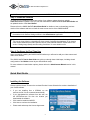
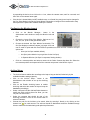
•
If you are installing from a CDROM, run the
autorun.exe file if it has not started automatically.
•
If you downloaded the software from the web, run
the NETDVRxxx.exe file from the location you
downloaded the software.
•
Click Install to install the NetDVR.
•
Click Next to continue the installation.
•
Please read and accept the License Agreement.
7
On-Net Surveillance Systems Inc.
•
Select Licensed Version option, and then click Next.
•
Please type in your Serial Number (Software License Code) as listed on your Product License Sheet.
•
Choose Installation Path, and then click Next.
•
Select Program Folder for the ONSSI shortcuts, click Next.
•
Select if you want to have shortcuts to be placed on the desktop (default is Yes), and if the
HTTP/RealtimeFeed Servers should be added to the startup folder (default is No). Then click Next.
•
Click Finish to complete the installation.
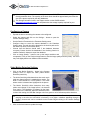
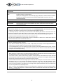
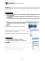
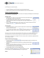
Retrieving Device License Keys
For each device (IP network camera or IP network video server) to be installed in the NetDVR software, a
Device License Key (DLK) must be obtained from On-Net Surveillance Systems.
•
Locate your Software License Code.
•
Gather all the MAC addresses of the devices to be licensed.
•
The MAC address asked for is a 12 digit hexadecimal (numbers 0-9 and letters A-F) and is by some
manufacturers referred to as a ‘Serial Number’. The MAC address is often written on the device itself.
If not, please refer to the device manual to learn how to find the MAC address.
•
Go to http://onssi.com/support/licensing.php.
•
Fill out the licensing form; please be sure to include your SLC and all your MAC addresses. To
ensure a timely response, please also include your complete name, address and phone number.
•
An email will be sent from support with your Device License Keys.
8
On-Net Surveillance Systems Inc.
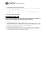
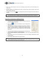
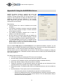
Importing Device License Keys
•
The DLKs received in the email from support can be typed in
manually when adding each device to the NetDVR software.
•
To avoid having to type in each DLK manually, save the file
attached to the email on a location of your choosing - for example
on a floppy disk.
•
Open the NetDVR Administrator by selecting Start, Programs,
NetDVR, Administrator, then click the Import DLKs button.
•
Browse to the location where you have placed the .DLK file. Select
the file, and then click Open.
•
All Device License Keys from the file are now imported and do not
need to be typed in manually.
Selecting Software Mode
The NetDVR software runs in two modes:
•
Console mode; when there IS a need to view live or playback video directly on the workstation
screens. The video can also be accessed using the NetGuard or the NetDVR Web Server.
•
Server mode; when there IS NO need to view live or playback video directly on the server running the
software. All viewing is done via the NetGuard or the NetDVR web server. Running the software in
‘server mode’ greatly reduces the load on your server and is strongly advised if live video does not
need to be viewed directly off of the server.
To enable ‘server mode’: in the NetDVR Administrator go to General Settings and check the ‘disable
screen update’ box. If running in ‘console mode’ no changes to the software need to be made.
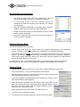
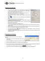
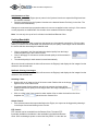
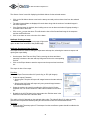
Adding a Device
•
Configure the IP address, password, etc. for the device as described by the manufacturer.
•
Click the Add Device… button in the Administrator Main Window.
•
Enter the device IP address or check the Use DNS host names check box and
enter the DNS name for the device. Click Next.
•
Type in the password for the Administrative user (usually root or admin). Leave
the Autodetect Device option selected.
•
When the device is detected, enter the Device License Key (DLK) for the
device (if the DLKs have been imported the field is pre-filled with the correct
DLK) and click Next. Please read the chapter Retrieving Device
License Keys for details about DLKs.
•
Assign a descriptive name to the device, and then click Finish.
•
The device is now installed successfully.
•
The name(s) of the camera(s) attached to the device can be changed
9
On-Net Surveillance Systems Inc.
by expanding the device, then click on the + icon, select the camera name, wait for a second, and
then click on the camera name again.
•
If the device is located behind a NAT enabled router, or a firewall, the port(s) used can be changed in
the Port Setup dialog in the Device Setup Wizard. Remember to configure the router/firewall to map
these ports to the ports and IP address used by the camera.
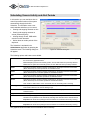
Configuring the Monitor Layout
•
Click on the Monitor Manager… button in the
Administrator main window to setup the Monitor look and
feel.
•
Choose the Layout Size of the Monitor. Options are 1x1,
2x2, 3x3, etc. up to an 8x8 grid camera layout.
•
Choose the desired Hot Spot Window functionality. The
Hot Spot displays a selected camera in a larger view, and
can be used for point-and-click Pan/Tilt/Zoom operations on some cameras. Possible Hot Spot
options are:
•
o
None (no Hot Spot enabled; default).
o
Hot Spot (select Monitor Layout grid size for the Hot Spot).
o
In Separate Window (Hot Spot is a separate, floating window).
Click on a camera position and select a camera in the Select Camera drop-down list. Select the
next camera position and repeat until all the cameras are present in the Monitor Layout.
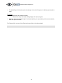
Archive Setup:
•
The Archive feature enables the recordings to be kept as long as desired, limited only by the
available hardware storage capacity.
•
Click on the Archive Setup… button in the
Administrator main window to set up the Archiving
features.
•
Click on the Enable Archiving button to enable
Archiving and select the number of days to keep the
databases (recordings).
•
Select a time and use the Add and Delete buttons to
modify the Daily archiving times list. Note, you can
only set one archive time.
•
Select the cameras that should be part of the
Archiving procedure. Click on the Set All button to
select all cameras.
•
Choose the path for the Archives to be stored, either by entering it directly or by clicking on the
browse icon
for each camera. The archives should be distributed across the available storage
drives to maximize the load sharing and optimize performance.
10
On-Net Surveillance Systems Inc.
When archiving to a network drive, the daily databases still MUST be recorded to locally (i.e.
directly) attached drives. The capacity of the local drives should be approximately two times the
size of the space required by the daily databases.
The Storage Calculator found in the Support section on the ONSSI website
http://onssi.com/support/nvr.php can help determine the storage capacity required for your
installation.
Configuring a Camera
•
•
•
•
•
•
Expand the device containing the camera to be configured.
Select the camera and click on the Settings… button to open the
Camera Settings dialog.
Set the Desired Framerate in the Framerate Settings area.
Configure where to store the camera database in the Database
Settings area. The path should be identical to the Archive path set for
the camera (if this is not a network drive).
Choose how the Monitor should react if the database becomes
corrupted. Choose Archive the databases if the Archiving function is
enabled. Default is Attempt to repair the database.
Click on Image Quality… button to set up the image resolution and
compression. Click on the Preview Image button to see the image quality and size (in KB). The menu
may look slightly different on different camera models.
Video Motion Detection Settings
•
Click on the Motion Detection… button in the Camera
Settings menu to adjust the VMD (Video Motion
Detection) sensitivity.
•
The Noise Sensitivity slider determines how much each
pixel can change before it is regarded as a motion. The
slider is most sensitive in its left position. The areas
where motion is detected are highlighted in the picture.
•
The Motion Sensitivity slider determines how many
pixels must change in the image before it is detected
as a motion. The sensitivity is indicated by the black
vertical bar in the VMD Bar. When the detected motion
is above this setting, the VMD Bar changes color from green to red to indicate a positive detection.
If there are areas in the image that should be ignored by the Motion Detection (such as a tree
swaying in the wind, an area which is irrelevant, or car lights / shadows appearing through a
window), these areas can be excluded via the Exclude Regions dialog in the Camera Settings
menu.
•
Click on the Auto button to update the image.
11
On-Net Surveillance Systems Inc.
•
Click on the Clear All button to clear the auto-settings, and de-select the Show Grid option for a
clearer view.
•
Mark the area(s) to be excluded from the VMD. Left mouse button marks a grid pixel, right mouse
button unmarks a grid pixel.
•
The Motion Settings should always be re-adjusted after the Exclusion Regions have been defined or
changed.
The VMD settings should be adapted to the actual application for each camera, and should be
verified under the different conditions applying for that position (day/night, windy conditions, etc.).
Image Server Administrator (NetGuard Client)
•
The Image Server service (called an Engine) is handling the NetGuard
access to the Monitor databases.
•
Click on the
shortcut on the desktop to open the Image Server
Administrator.
If the Image Server should be accessed from the Internet or a different
LAN via a router or firewall, the Enable Outside Access must be
enabled. The outside (public IP or LAN Router) IP address and port
must be specified in the Outside IP Address and Outside Port fields
respectively.
•
•
•
•
•
The router must be configured to forward requests to this address and
port to the inside (local) server IP address and port.
The user rights are defined in the User Administration. Click on the User Setup button to set up
the users.
The privileges of each user must be defined in the User Access dialog if restricted user access
has been chosen.
Set the days to keep the log file in the Log Files area.
The Image Server runs as a service. Please check that the service is running if you cannot
connect to the Image Server. The service will not start if another application or service is using
the port specified in the Image Server Administrator.
12
On-Net Surveillance Systems Inc.
Remote Access Servers
•
The Remote Access Servers are an alternative to the Image Server
to obain remote accessibility. This is facilitated by the ONSSI Web
Server and the ONSSI Realtimefeed Server.
•
Both servers can be started from the Start menu if they have not
been added to the Startup Folder on installation.
•
The Web Server handles navigation and still image viewing. Default
port is 81.
•
Click on in the system tray to open the Web Server configuration
dialog.
Click the Settings button to start configuration.
By default, the web server is set to allow access without entering a
password (Allow Anonymous Access).
Select Access For Predefined Users Only if you want to allow
access only for known users.
Click the User Setup button to define the users.
To restrict which cameras each predefined user can access, select the Restrict User Access by
Camera option.
Click the User Access button to set up which cameras and options each user will have access to.
Click on Hide Window to close down the Web Server window.
•
•
•
•
•
•
•
•
•
The Realtimefeed Server
handles all streaming video. Once started, it does not need any
configuration. Default port is 9513.
To test the Remote Access functionality, type http://localhost:81 in the Internet Explorer on the
NetDVR Server PC.
Uninstalling the Software
The ONSSI NetDVR software can be uninstalled as
follows:
•
Shut down the HTTP and Realtimefeed Servers if they
are running.
•
Open the Add/Remove Programs dialog in the Control Panel.
•
Select the ONSSI NetDVR entry, and then click Change/Remove.
•
If you want to keep your existing configuration and/or databases, make sure the Remove Database
Files and Remove Registry Settings options are unchecked. Then click OK.
•
Click Finish and close the Add/Remove Programs dialog and the Control Panel Window.
13
On-Net Surveillance Systems Inc.
Program Help
The Administrator, Monitor, and Browser applications have context help for all available functionality.
You obtain help by pressing the question mark icon in the program's active window (or in some windows, the Help
button). The cursor will turn into a “What’s this” cursor and you can now click on the item that you need help with.
Afterwards, click anywhere with the mouse in order to remove the help pop-up window.
Obtaining Support
If you have questions or problems not answered in this manual, please contact your ONSSI Software dealer or visit
the ONSSI Surveillance Support site at www.onssi.com.
14
On-Net Surveillance Systems Inc.
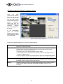
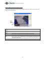
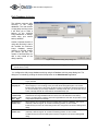
Administrator Manual
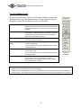
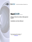
The Administrator application is used when setting up the system for first time use, when new cameras
are added to the system, and whenever the system configuration needs to be changed. This tool is also
used to configure the screen layout of the Monitor application, which recording conditions to use, etc.
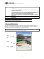
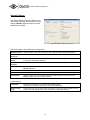
Start the Administrator from the Program Menu.
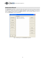
Figure 1: Main dialog box of the Administrator application
15
On-Net Surveillance Systems Inc.
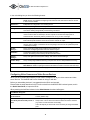
In the main dialog box you have the following buttons:
Add Device…
Add new video camera or video server devices to the system. Please refer to the Quick Start
Guide and the more detailed "Configuring Video Cameras and Video Server Devices" section
in this manual for details.
Edit Device…
Edit/update the configuration of an existing device.
Remove Device
Remove an existing device from the system.
Settings…
Set up image quality and recording conditions, etc. for the camera.
See section "Setting Image Quality and Recording Conditions".
I/O Setup…
Define inputs and output that you would like to have available on the system. Inputs can be
used to create an alert or start/stop a camera. Outputs can activate the output ports on
selected devices and thereby make it possible to turn on e.g. a siren or the light.
I/O Control…
Setup defined inputs to activate selected outputs. More inputs can activate the same output.
Both external inputs and timer events can be used to activate an output.
Event Buttons…
Define buttons to be placed on Monitor screen. These buttons allow the user to trigger an event
with the click of a button. This button can do many things, such as move to a particular preset
or start/stop recording.
Monitor
Manager…
Set up screen layout and screen positions of the cameras, etc.
See section "Configuring Monitors and User Interface Layout".
Scheduler…
Control when cameras are online and when alerts are given.
See the "Scheduling Camera Activity and Alert Periods" section.
General
Settings…
Set up user rights and other system settings. See section "General Settings".
Archive Setup…
Set up of daily image database archiving if required. See section "Daily Database Archiving".
Import DLKs…
Import the DLK file generated by the ONSSI DLK retrieval system. Please refer to the Quick
Start Guide for details. Importing the DLK file eliminates the need to enter the DLKs manually!
NetMatrix…
Enabled when the ONSSI NetMatrix plug-in is installed only.
Configuring Video Cameras and Video Server Devices
When you have installed the software you will need to configure it for all your video camera and video
server devices. The NetDVR Add Device Wizard will help you with this.
Before you start adding devices it is suggested that the DLKs are imported.
Please follow the steps described in the E-mail received from the NetDVR DLK retrieval system, and in
the Quick Start Guide, to import the DLKs.
When pressing the Add Device button In the Administrator the wizard will appear:
First Wizard dialog box:
The video device has this IP-address
on the network:
Enter the IP address of the device on your network (Note: Not needed with
a frame grabber card).
Click the 'Port Setup' button if other
than HTTP port 80 and FTP port 21 is
used
The HTTP and FTP ports used can be changed by clicking the "Port
Setup" button. This is used if more devices share the same IP address
(e.g. behind a router with NAT functionality).
In the vast majority of cases it will not be necessary to change the default
ports.
16
On-Net Surveillance Systems Inc.
Second Wizard dialog box:
The password for the video device
administrator account is:
Please enter the password for the video device's administrator account
(sometimes called 'root' or 'admin').
Auto detect Device
For fast detection you can select the video device type. You can also keep
the 'Auto Detect Type' selection and let the system find the device type.
Third Wizard dialog box:
DLK:
Please enter the Device License Key (DLK) for the MAC address. The
DLK will appear automatically if the SLC.dlk file received by E-mail was
imported (See the E-mail for details).
Fourth Wizard dialog box:
Show this name for the video device:
Please enter a name that will help you identify the device later, e.g.
"Entrance Door, "Sales office" etc.
Note that the system does not allow two devices with the same name.
Press the Camera Setup button to
set up camera names and PTZ
devices for this device.
Press the Camera Setup button if changes should be made to the default
camera name (Camera 1). For multi-channel video servers the camera
names are Camera 1, Camera 2, etc.
PTZ devices (PTZ cameras or fixed cameras on PTZ foots) should be
enabled and the COM port and driver selected. For more detailed
information see the sub section “Configuring Video servers" found in the
next section ("Changing Device Settings").
After a device has been successfully added a new device icon will appear in the "Device Manager" window. Press the
"Add Device…" button again in order to set up remaining devices.
17
On-Net Surveillance Systems Inc.
Changing Device Settings
Changes to HTTP/FTP ports, IP addresses and device/camera names can be done by selecting the
device in the "Device Manager" window and subsequently pressing the "Edit Device…" button.
In the Identify Video Device area the following information is found:
Device Type
The type of device you are using. (The device type can be found automatically if you press the
Detect Device button and the correct IP-address and Device Password have been specified).
Device Name
The name that helps you identifying the device in the software, e.g. "Entrance Door", "Meeting
Room 1" etc. Note that the same name can not be used for more than one device.
Device Serial
Number
The serial number (usually the MAC address) of the device, e.g. 00408c291ba2. The serial
number is usually found on a label on the device (can also be found automatically with the
Detect Device button if the correct IP-address and Device Password have been specified).
Device License
Key
16 characters license key associated with the device, e.g. c5a8ff0c89679490 (See Step 1
"Obtain Device License Keys").
Enable iPIX
With iPIX 180 degrees image technology it is possible to PTZ in images taken by a fisheye lens
camera. The iPIX technology converts the fish-eye lens image to a normal looking image in
which you can move around, covering a much larger area than with a normal lens camera.
iPIX License Key
License key for enabling iPIX technology for the specific device. The iPIX License Key is
obtained in the same way as DLKs, using the iPIX License Code instead of the Software
License Code. If using an iPIX device the license is not needed. It is only needed when using a
non-iPIX device while using the iPIX technology.
In the Network Settings area the following information is found:
IP-address
The IP address of the device on your network.
Default HTTP port
Select this option if HTTP traffic to the device should go through port 80 at the specified IPaddress.
Deselect this option if a non-standard HTTP port should be used and specify the port in the
field to the left of this checkbox.
Default FTP port
Select this option if FTP traffic to the device should go through port 21 at the specified IPaddress.
Deselect this option if a non-standard FTP port should be used and specify the port in the field
to the left of this checkbox.
Root Password
The password required when logging on to the device using the “root” (sometimes called
"Admin") account.
In the Audio area the following information is found:
Audio Enabled
Available if audio is supported for the device. Select the option to enable audio through the
device. Audio requires DirectX 8.1 or higher, which means that audio is not possible when
using NT 4.0.
18
On-Net Surveillance Systems Inc.
Configuring Video Servers
For Video Servers you need to specify if the connected cameras are Pan/Tilt/Zoom cameras and you can
also give the individual camera a name.
In order to do this, press the Camera Settings button and the Camera Settings for Device dialog box will
appear.
In the PTZ Camera Selection area the following information is found:
Some of the
connected
cameras …
Select this option if any of the connected cameras are Pan/Tilt/Zoom cameras.
PTZ type
controlled
through COM1
If you are controlling the PTZ functionality of one or several cameras through the COM1 control
port of the device then you must select the correct PTZ camera type in the list box. If you are
not controlling any devices through this port, select "None".
PTZ type
controlled
through COM2
If you are controlling the PTZ functionality of one or several cameras through the COM2 control
port of the device then you must select the correct PTZ camera type in the list box. If you are
not controlling any devices through this port, select "None".
In the camera list box you will see a line for each camera channel on the Video Server. First line (Camera
1) corresponds to camera channel 1 and so on. In order to specify the settings for e.g. Camera 1 click
once the first line, it will then become selected. In the configuration area below you have the following
options:
Camera
Name
Enter a name of the camera for you to remember it by. E.g. a name
related to its location, such as "Main Entrance".
Camera Type
If the camera is a PTZ camera select "Movable", otherwise select "Fixed".
Device Port
Enabled if "Movable" is selected as Camera Type:
Select, which control port on the Video Server, should be used to control
the PTZ functionality of the camera.
Port Address
Enabled if "Movable" is selected as Camera Type. Specify the port
address of the camera, which would normally be 1 or 0. If using daisy
chained PTZ cameras the port address identifies each of them. Please
refer to the camera manual for more information.
Pressing the Apply Changes button will show the updated information in the camera list box. Press the
OK button when you are done.
19
On-Net Surveillance Systems Inc.
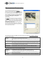
Configuring Monitors and User interface Layout
When
you
have
configured the software
for your camera and
video server devices
then you need to select
which screen layout the
Monitor
application
should use, and you
must specify where the
individual
cameras
should be displayed on
the screen.
In the Administrator
press
the
Monitor
Manager button and the
Monitor Manager dialog
box will be shown.
Figure 2: Monitor Manager dialog box
In the Monitor Manager dialog box you have the following options:
Layout Size
HotSpot Window
Select how many monitors (i.e. camera windows) you wish to appear on your screen. Select
between 1x1 to 8x8 monitor views.
The Hotspot Window is a secondary camera window that can show an enlarged view of a
selected camera. It can also be used for interactive PTZ control and to browse through
previously recorded images (Quick Browse).
• Select "None" if you don't want the HotSpot window to appear.
• Select "HotSpot" and the desired size of the window if you do want the HotSpot window to
appear in the Monitor window.
• Select “In separate” window if you want the hotspot to appear in a resizable, floating window.
The floating Hotspot Window can be switched on and off from within the Monitor application.
Select Camera
Select which camera to show in the selected monitor. You assign the cameras to the monitors
by (a) clicking with the mouse on the monitor you want to assign a camera to and (b) selecting
the desired camera in the Select Camera drop down box.
Settings…
This button will take you directly to the Camera Settings dialog box for the currently selected
camera. See the "Setting Image Quality and Recording Conditions" section for more
information.
20
On-Net Surveillance Systems Inc.
Setting Image Quality and Recording Conditions
For each of your cameras you can set the desired image quality, recording speed, and other conditions
for the recording of images. When recording sound from a device, the database setup for the sound
recording is also managed from here.
In the Administrator main dialog's tree-view, select the camera in question and press the "Settings…"
button. The Camera Settings configuration dialog box will be shown.
You can also invoke this dialog box by pressing the Settings… button in the Monitor Manager dialog box.
In the Framerate Settings area you specify the recording speed of the camera:
Desired
Framerate
Specify the desired recording speed by entering the number of frames you wish to retrieve from
the device each second, minute or hour. This will give you a recording range from 24 images
per day up to 30 images per second (25 images per second for PAL).
Enable Speedup
Select this option if you want to increase the framerate on motion detection and/or an external
event.
“On motion”: Increase the framerate when motion is detected. The framerate will revert to its
original (lower) speed two seconds after the last motion is detected.
“On event”: increase the framerate when the specified external Start event is detected. The
framerate will revert to its original speed when the specified external Stop event is detected.
Please refer to Appendix A: ”Advanced Camera Control with Sensors” section of this manual
for details of how to set up external events.
Desired speedup
framerate
When the Enable Speedup option is selected, the desired (higher) recording speed is specified
here by entering the number of frames you wish to retrieve from the device.
This higher recording speed will be used whenever the speedup conditions are met, as
specified under Enable Speedup.
As with the desired framerate setting this will give you a recording range from 24 images per
day up to 30 images per second (25 images per second for PAL).
In the Image Storage Settings area you specify the conditions for the recording:
When to store
images in
database
Specify when to store the received images for this camera in the database.
“Always”: Unconditionally store all received images in the database.
“Never”: Never store any images in the database. Images are still displayed in the Monitor
window but can not be viewed via the web interface.
“Conditionally”: Store the images to the database when the specified conditions are met only.
On motion: Store all images with motion (default setting)
On Event: Store all images (regardless of motion) when the defined Start event occurs until the
defined stop event occurs.
Both conditions can be used alone or combined. When both options are ticked images are
stored in the database if just one of the conditions is met.
Pre/Post buffer
The number of seconds to store before and after the conditions for storage is met.
21
On-Net Surveillance Systems Inc.
In the Database Settings area you specify how many images you want to store in your image database
and the location of the image database files on your disk:
Max. images in
database
Select this option to limit the image database for the camera to a maximum size. When the
maximum number of images has been recorded, the oldest image in the camera database will
be overwritten automatically, each time a new image is received. The maximum size that can
be specified is 600.000 images.
Delete images
older than
Select this option if you want the recordings in your image database for the camera to be
limited by age. If this option is selected the images will automatically be deleted when they are
older than the specified number of minutes, hours or days.
Please note that you will not be able to store more than 600.000 images regardless what
maximum age has been specified.
Database Path
Specify the main directory on your disk to keep the image database. A sub directory for this
camera will be created by the system, but the main directory you specify must exist; it will not
be created automatically.
To achieve the best performance, it is recommended that you specify a location on a local hard
disk, not on a network drive.
Browse path (…)
Press this button if you wish to browse for the database path directory.
Clear Database…
Press this button if you wish to delete all images recorded for this camera. Caution: All your
recordings for this camera will be permanently lost (This does not include archived databases).
Delete Audio
older than
Select for how long audio recordings should be kept in number of minutes, hours or days.
When older than specified, sound recordings will be deleted unless they have been archived.
Audio archiving is done automatically if the image database archiving functionality is activated.
In Case Of
Database
failure…
In case of a database failure, five image database recovery options are available.
“Repair, Scan, delete if fails ”: The database repair function will attempt a fast scan repair; if it
fails attempts a full scan repair; if that also fails the DB is deleted. Please note that no images
can be recorded while the database repair function is running. For large installations this can
take several hours.
“Repair, Delete if fails”: Attempts a fast scan repair; if it fails the DB is deleted.
*“Repair, Archive if fails”: Attempts a fast scan repair; if it fails the DB is archived.
*"Archive (No repair)"
No repair is attempted and the DB is just archived.
"Delete (No repair)"
No repair is attempted and the DB is just deleted. The first time the archived database is
opened in the Browser the database repair function will start repair of this specific database.
*Please note that this option is available only if archiving has been set up for this camera.
Please refer to the chapter Daily Database Archiving in this manual for details.
In the case recordings get bigger than expected or the available disk space is suddenly reduced in another way,
an advanced database re-sizing procedure will automatically take place. If archived databases are present on the
disk containing the current database the oldest archive for all cameras on that disk will be deleted. If no archives
are present the database size of the current databases will be reduced, so that a percentage of the oldest
recordings will be deleted and each database size will temporarily be limited to its new size. You will be informed
on the screen, in the log-files and optionally through E-mail (if setup) and SMS (if setup).
When the Monitor application is restarted the old database sizes will be used. It is therefore up to the user to
adopt the new sizes or solve the disk size problem in another way.
22
On-Net Surveillance Systems Inc.
In the Camera Monitor Setup area you specify how your camera is displayed in the Monitor:
Show Motion
Select this option if you want the detected motion to appear highlighted in the image. If
selected, the areas of the image with motion will be colored with the selected motion color.
Clicking the "Motion Color…" button in the "Motion Detection Settings" area will allow you to
change the motion color used.
Show Regions
Select this option if you want the areas in which motion detection has been excluded (disabled)
to appear highlighted in the image. If selected, the areas will be colored with the selected
region color.
Clicking the "Region Color…" button in the "Exclude Regions Settings" area will allow you to
change the region color used.
Update on motion
only
Select this option if you only want the camera to be updated on your screen when motion has
been detected. Enabling this option greatly reduces the workload of the PC. It is therefore
recommended that you select this option if the PC runs primarily as a server, serving clients
through the built-in Web Interface.
Note: It is possible to disable screen updating completely in the General Settings menu.
Enable iPIX
Select this option if iPIX technology should be applied to the camera. When selected, a fish-eye
image will look like an image from an ordinary camera lens.
Note: Only available if iPIX have been activated for the device.
IPIX Settings
Click this button to configure the iPIX Technology for the camera. IPIX conversion of a fish eye
image to a normal image is based on this configuration. The configuration is described in
Appendix C.
In the Motion Detection Settings area you have access to setting up motion detection for the camera:
Motion
Detection…
Press this button in order to calibrate the motion detection. Please refer to the Calibration of
Motion Detection section for details.
Motion Color…
Press this button to select a new motion color. Please refer to the "Show Motion" option in the
Camera Monitor Setup section.
In the Exclude Regions Settings area you have access to setting up regions for the camera that should
be excluded from motion detection:
Exclude
Regions…
Press this button in order to specify if certain areas of the images should be excluded from the
motion detection. Please refer to the "Defining Motion Detection Exclude Areas" section for
details.
Region Color…
Press this button to select a new region color. Please refer to the "Show Regions" option in the
Camera Monitor Setup section.
In the bottom of the Camera Settings dialog box two (three) buttons are found:
Image Quality…
Activates the "Configure Device" dialog box. Here the camera image quality, including image
size and compression, can be set up. A preview image can be shown with the current selected
settings.
Outputs…
Click this button to set the output settings for the current camera. In this dialog you can select
which defined outputs should be enabled if motion is detected for this camera. You can also
specify up to five buttons that will be available in the monitor application when the camera is
selected. Each button can control an output to be activated manually. Note: Access to defining
outputs is gained by clicking the I/O Setup button in the Administrator main dialog box.
PTZ Preset
This button is only shown when Pan/Tilt/Zoom is set up for the camera, and the camera
23
On-Net Surveillance Systems Inc.
Positions…
supports absolute positioning, or the device driver supports import of relative PTZ positions
from the device.
Up to 25 preset positions per absolute positioning PTZ camera can be defined in the PTZ
Preset Positions dialog box activated by this button. Each preset position can later be instantly
accessed in the monitor application.
For relative positioning PTZ cameras defined preset positions on the video server (AXIS or
Convision) will be listed and used instead. These preset positions must be defined through the
web interface of the device before they are available in the NetDVR software.
The "PTZ patrolling" and "PTZ goto on event" features are both enabled and set up from this
dialog as well.
Event Notification
Move an event from list of “Available Events” to “Active Events” to have orange LED light up in
NetDVR Monitor.
For detailed information about PTZ preset positions and their use, please refer to the
section "Setting Up and Using PTZ Preset Positions.
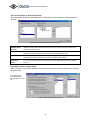
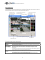
Calibration of Motion Detection
The motion detection system may control (a) when images are saved to disk and (b) when alarms are
generated, and it is therefore a vital element of the system. Motion detection needs to be calibrated
carefully otherwise it will not function properly. Do this as described below.
It is recommended that you set up the image quality to be used, and that any regions excluded from motion
detection (if any) are defined before you calibrate the motion detection.
Detected
motion is
shown with the
selected motion
color
Motion Level
Indicator
Alarm
threshold
indicator
Figure 3: Motion Detection Calibration dialog box.
24
On-Net Surveillance Systems Inc.
Motion Level
Indicator
Indicates the current level of detected motion in the image. The indicator is green when the
level is below the threshold and will turn red when the threshold is exceeded.
Alarm Threshold
Indicator
Indicates the selected motion alarm threshold. A motion alarm will be generated when the
motion level goes beyond the threshold.
Noise Sensitivity
Slider to adjust the noise sensitivity level of individual picture elements (pixels). The noise
sensitivity level controls when the change in light intensity and color (light change) of individual
pixel should be considered noise (i.e. an insignificant change) and when it should be
considered motion (i.e. a significant change). In the live updating camera image you will see the
pixels in which motion has been detected marked with the selected motion color (which is green
by default). In order to understand how it works, try to drag the slider to position "high" and
watch how the whole camera image will turn green.
Drag the slide bar back to the optimal position, where only the pixels affected by significant light
changes are marked with the motion color.
Motion Sensitivity
Slider to adjust the motion sensitivity. The motion sensitivity controls the alarm threshold and
thereby determines the minimum size of an object that will generate an alarm.
Drag the slider until the alarm threshold indicator is at the optimal position.
Trees and bushes outdoors and plants indoors may generate undesired noise, you may find that you can define
motion detection exclude areas to eliminate this noise.
Some video cameras generate undesired noise at poor light conditions. In order not to generate undesired
alarms, you may find that you need to reduce the noise sensitivity or to improve the light condition.
25
On-Net Surveillance Systems Inc.
Defining Motion Detection Exclude Areas
You can define motion detection exclude areas if you wish to exclude (i.e. mask out) certain areas of the
image from the motion detection.
Squares
excluded
from motion
detection
Figure 4: Define Exclude Regions dialog box.
Left mouse
button
Exclude square from motion detection.
Right mouse
button
Include square in motion detection.
Set All
Press this button to exclude all squares (whole image) from motion detection.
Clear All
Press this button to include all squares (whole image) in motion detection.
Auto
Press this button to make the software detect noisy areas automatically and exclude them from
motion detection. Note that the motion detection must be reasonably well calibrated before this
auto detection feature will work.
Show grid
Select this option if you wish the grid lines to appear in the image.
26
On-Net Surveillance Systems Inc.
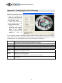
Setting Up and Using PTZ Preset Positions
Up to 50 PTZ preset positions per absolute
positioning PTZ camera can be made accessible in
the control panel of the NetDVR Monitor application.
Note: To setup PTZ Presets or patrolling, please go
to the ‘PTZ Presets Positions’ page located under
the cameras setting page in the NetDVR
Administrator.
For relative PTZ cameras the number of positions
will depend on the video server (AXIS or Convision)
and the PTZ driver used. Only the preset positions
defined on the video server will be listed, and only
these positions can be used.
The PTZ preset positions dialog box is activated
from the camera settings dialog box by pressing the
PTZ Preset Positions button.
Figure 5: PTZ Preset Positions dialog box
The following functionality is available in the PTZ View area of the dialog (only available for absolute
positioning PTZ cameras):
Wide/Tele
Click on the bar to set the zoom level for the camera.
When clicking, the zoom level will be set to the level indicated by the cursor position on the
bar.
Tilt (Vertical bar)
Click on the bar to set the tilt position for the camera.
When clicking, the tilt level will be set to the level indicated by the cursor position on the bar.
Pan (Horizontal
bar)
Click on the bar to set the pan position for the camera. When clicking, the pan level will be set
to the level indicated by the cursor position on the bar.
Pan/Tilt buttons
Press the buttons in order to move the camera in the direction indicated by the button.
Zoom buttons
Press the buttons in order to zoom in or out.
In the Preset Position area you find the following functionality:
Use Preset
Positions from
Device *)
For absolute PTZ cameras it can be chosen whether the preset positions on the video server
should be used or if preset positions defined in the NetDVR should be used.
For relative PTZ cameras, defined positions on the device will automatically be used, i.e. the
option cannot be unchecked.
Set Position
Press the Set Position button when the PTZ camera has been moved to the desired position.
27
On-Net Surveillance Systems Inc.
(Absolute)
This will save the position as the (new) preset position for this entry.
Note that names will be truncated if they are too long for the preset position buttons in the
Monitor application.
Edit Name…
(Absolute)
Select a preset position in the list and press this button to change the name of the preset
position if required.
Test
Move the camera to the selected preset position.
Delete (Abs.)
Remove the selected preset position from the list.
Preset position
list
List of all defined preset positions. The list is divided into five groups, A, B, C, D and E, each
with 5 preset positions. In the Monitor application the preset positions will be shown in these
groups of five. Each group has its own button for fast access in the Monitor.
List control
buttons
Use the arrow up and down buttons in the preset positions area to change the order of the
listed preset positions. Selected a preset position and move it up or down the list by using the
arrows.
*) Selected devices only, please see the release note for details.
In the Patrolling and Preset Position on Event area the following options exist:
None
If preset positions should only be used manually, select this option.
Goto preset on
event
Select this option if the PTZ camera should automatically go to a preset position when an event
occurs. More events can be connected to the same preset position.
The goto preset on event feature will be active when scheduled mode is activated and PTZ
mode is not selected for the camera.
Patrol when
camera is online
Select this option if the PTZ camera should patrol among selected preset positions when
online.
The patrol feature will be active when scheduled mode is activated and PTZ mode is not
selected for the camera.
28
On-Net Surveillance Systems Inc.
Goto Preset Position on Event feature Setup
When clicking the setup button associated with the Goto preset on event selection, the following dialog
will show:
Figure 6: Goto Preset Position on Event dialog box
Available Preset
Positions
Select the preset position that the camera should move to when the events selected in the
"Available Events" list occur.
Available Events
Select the event that should move the camera to the preset position selected. You can select
between both external events and timer events in the "Available Events" list.
>> (Add button)
Click the add button ">>" and the selected event will appear in the rightmost list, containing all
events that have been connected to the currently selected preset position.
<< (Remove
button)
To remove an event from the list, select the event in the rightmost list and click the remove
button "<<".
Patrol When Camera is Online Setup
`When clicking the setup button associated with the Patrol when camera is online selection, the following
dialog will show:
In the Setup PTZ
Patrolling dialog the
following options can be
set:
Figure 7: Setup PTZ patrolling dialog box.
29
On-Net Surveillance Systems Inc.
Stay at each
position…
Indicate for how many seconds the PTZ camera should stay at each preset position included in
the patrol schedule.
Time for each
PTZ camera…
Indicate the number of seconds for the PTZ camera to complete a PTZ command in worst
case. In order not to produce a false motion alert, motion detection is disabled from the time the
camera is send to the next preset position in the patrol and until the indicated time has expired.
It is therefore important that the PTZ camera is in place at the next position before the time
expires.
In the PTZ Patrol action on motion area the following functionality is set:
Disable patrolling
schedule…
Select this option if motion detected during a patrol schedule should temporarily disable the
schedule and await one of the two options available (see below)
Seconds has
passed since…
Select the first option if the PTZ camera should stay for the indicated number of seconds after
motion was detected for the first time.
Seconds has
passed without…
Select the second option if the PTZ camera should keep the position until motion has not been
detected for the indicated number of seconds.
In the Select preset positions to be used for patrolling area the following functionality is found:
Preset positions
Shows the list of all defined preset positions for the camera. Positions that should be added to
the schedule are selected in this list.
>> (Add button)
Click this button to include the selected preset positions from the "Preset position" list in the
"Patrolling list". A preset position can be added more than once, so that an important preset
position can be visit more than once during the schedule.
Note that multiple selections are possible. Hold down “Ctrl” on the keyboard to select additional
positions with the mouse or hold down “Shift” to select a range of positions by clicking the
first/last position with the mouse.
<< (Remove
button)
Click this button in order to remove the selected preset positions from the "Patrolling List". Note
that if a preset position is included more than once in the "Patrolling list", only those instances
selected will be removed.
Note that multiple selections are possible. Hold down “Ctrl” on the keyboard to select additional
positions with the mouse or hold down “Shift” to select a range of positions by clicking the
first/last position with the mouse.
Patrolling list
Shows the list of all included preset positions in the patrol schedule. A preset position can be
included more than once in the list, so that an important preset position can be visit more than
once during the schedule.
Move up button
Move the selected preset position up in the "Patrolling list". The preset position visits will be
executed in the order they are listed, with the upper preset position as the first.
Move down
button
Move the selected preset position down in the "Patrolling list". The preset position visits will be
executed in the order they are listed, with the upper preset position as the first.
30
On-Net Surveillance Systems Inc.
General Settings
The General Settings dialog box allows you to
define which rights the user/operator has when
using the Monitor application and to set other
administrative settings.
Figure 8: General Settings dialog box
Define user rights in the Administrator Settings area:
Enable Protection
Select this option if you want to restrict the user's rights and enable password protection.
Change
Password…
Press this button to change the administrator password.
Application
Startup
Select this option if the user should be allowed to start the Monitor application without having
to specify the administrator password.
Application
Shutdown
Select this option if the user should be allowed to close the Monitor application.
Manual Control
Select this option if the user should be allowed to start and stop the cameras manually in the
Monitor application.
Browser
Select this option if the user should be allowed to start the browser in the Monitor application.
PTZ Control
Select this option if the user should be allowed to enable PTZ mode in the Monitor application.
Quick Browse
Select this option if the user should be allowed to invoke the Quick browse feature in the
Monitor application (requires HotSpot window).
Logfile Settings:
Logfile Path
Specify in which directory on your disk to keep system log files.
The directory you specify must exist; it is not created automatically.
Number of days
to log
Specify how many days you want to store the log files. A new log file will be created each day.
Log files older than the specified number of days will be deleted automatically.
31
On-Net Surveillance Systems Inc.
Advanced settings:
Disable Screen
Update
Select this option if the Monitor screen is not used on a daily basis by an operator but only used
when setting up the software. All Monitor screen updating will be disabled. This can free up
resources that may result in better system performance.
Keyframe-only
decoding…
When running a camera in MPEG4 compression, the user has the option for the system to only
decode and display video from Keyframe. This means that if the keyframe is sent once every
five seconds, the NetDVR Monitor will only update once every 5 seconds. This does not affect
the recording rate.
Don't send E-mail
on camera failure
Select this option to disable sending of an E-mail whenever a camera failure occurs (This will
only happen if E-mail is enabled).
When not selected, camera failure E-mails will be sent if E-mail has been enabled. Note that
this will be carried out at any time regardless of scheduled E-mail alert periods set in the
Scheduler.
Don't send SMS
on camera failure
Select this option to disable sending of an SMS whenever a camera failure occurs (This will
only happen if SMS is enabled).
When not selected, camera failure SMS' will be sent if SMS has been enabled. Note that this
will be carried out at any time regardless of scheduled SMS alert periods set in the Scheduler.
Add Monitor to
Startup group
Makes sure the Monitor is always started up when the PC is booted.
Uncheck this box if you do not want the Monitor to start automatically (it is not sufficient to
simply remove the Monitor icon from the Windows Startup folder).
Other administrative settings:
E-mail Settings…
Press this button to change the settings for E-mail alerting. See Configuring E-mail Alerting
below.
SMS Settings…
Press this button to change the settings for SMS alerting. See Configuring SMS Alerting below.
Configuring E-mail Alerting
The E-mail alerting system needs to be configured before it can be used; you do this in the E-mail Setup
dialog box in the following way:
Enable
E-mail
Select this option in order to enable E-mail alerting.
Advanced…
If Simple MAPI mail client is not available, it is possible to configure SMTP E-mailing instead.
SMTP can also be used if the mail client requires confirmation before sending E-mails.
Recipient(s)
Specify the E-mail address of one or more recipients. Use a semicolon (;) to separate the
addresses if more than one recipient is specified.
E.g.: [email protected]; [email protected]
Subject Text
Specify the text string to be used as the subject for the E-mails sent.
Message Text
Specify the text string to be used as the message (body) for the E-mails sent. The name of the
device and camera that generated the alarm will automatically be appended to the text.
Include Image
Select this option if you want the image that generated the alert to be attached to the mail.
Time btw. Mails…
Specify the minimum number of minutes between the alert E-mails for the individual camera or
0 (zero) if each motion detection should result in an alert E-mail. A motion alert from a camera
will not generate an alert E-mail if the minimum number of minutes specified has not elapsed
Note: Camera failures and system failures will automatically be sent through E-mail if this has
not been disabled under "Advanced" in the "General settings" dialog box
32
On-Net Surveillance Systems Inc.
since the last alert E-mail for the camera was sent.
Background information: During a longer period of constant motion a high number of alarms will
be generated; it may not be desirable that an alert E-mail is sent for every alarm.
Test button
Press this button to send a test mail to the specified recipient(s).
The Scheduler controls during which hours of the day the motion alert E-mails are sent and which cameras
should be generating the E-mails. See the section “Scheduling Camera Activity and Alert Periods" for more
information.
Configuring SMS Alerting
The SMS alerting system needs to be configured before it can be used; you do this in the SMS Settings
dialog box in the following way:
Enable
SMS
Select this option in order to enable SMS alerting.
GSM terminal
connected to
Specify which serial port on the PC you have connected the GSM terminal to.
SIM card PIN code
Specify the PIN code of the SIM card inserted in the GSM terminal.
SIM card PUK code
Specify the PUK code of the SIM card inserted in the GSM terminal.
SMS central phone
no.
Specify the phone number of the SMS central to receive your calls.
Recipient phone no.
Specify the phone number of the GSM phone to receive the SMS alert messages.
Message
Specify the text of the message to be sent.
Note: Camera failures and system failures will automatically be sent through SMS if this has
not been disabled under Advanced in the General settings dialog box.
Note that:
• a maximum of 100 characters is allowed,
• only characters in the ranges a-z, A-Z, 0-9, comma and punctuation mark are allowed.
Time btw.
Transmissions…
Specify the minimum number of minutes between the SMS alerts for the individual camera or
0 (zero) if each motion detection should result in an SMS alert. A motion alert from a camera
will not generate an SMS alert if the minimum number of minutes specified has not elapsed
since the last SMS alert for the camera was sent.
Test button
Press this button to send a test SMS message to the specified recipient.
The SMS Alerting System requires that a GSM terminal has been connected to one of the serial ports of the PC.
The software has been designed specifically for the Siemens M20 GSM terminal, but will also work with other
GSM terminals compatible with the M20 terminal.
Using the same GSM provider for the GSM terminal and the receiving GSM phone will most likely give you the
fastest and most reliable service.
33
On-Net Surveillance Systems Inc.
Daily Database Archiving
The software supports daily
archiving of the image
databases. The main benefit
of using daily archiving is that
it will allow you to make a
backup of the archived
image databases on backup
media using your normal
backup software.
Another important benefit of
using daily archiving is that it
will increase the maximum
image database storage
capacity to 600.000 images
per camera per day. The
number of archived days on
disk is only limited on the
disk(s) capacity.
Figure 9: Database Archiving setup dialog box
Note that a storage capacity of 600.000 images per day corresponds to storing approximately seven images per
second 24 hours a day.
You configure the daily image database archiving using the Database Archiving setup dialog box. The
dialog box is invoked by pressing the Archive Setup button in the Administrator application.
Enable Archiving
Select this option if you want to use the daily image database archiving feature for one or more
of your cameras.
Perform archiving
every day at
Specify at which time of the day you want the daily archiving to occur. Note that the cameras
will be stopped (i.e. not recording) one by one while the archiving takes place. You should
therefore aim at choosing a time of the day where nothing of importance should be recorded. If
you are also backing up your image database to a backup media, then you should also choose
a time of the day that will not conflict with the scheduled backup job.
Delete databases
in the backup
directory older
than… days
Specify how many days you want to store the archived image databases. Each day at the
selected time the image databases will be moved to new sub-directories in the backup
directory. Sub-directories containing archived image databases older than the specified number
of days will be deleted automatically.
Send email on
archive error
When selected, an E-mail will be sent if the system fails to archive a database. This may be
caused by a disk running full, as a result of networking problem, or other causes.
Emails will only be sent if the email settings have been configured in the General Setting email
dialog.
Send SMS on
archive error
When selected, an SMS will be sent if the system fails to archive a database. This may be
caused by a disk running full, as a result of networking problem, or other causes.
An SMS will only be sent if the SMS option has been configured in the General Setting SMS
dialog.
34
On-Net Surveillance Systems Inc.
Camera archive
selection list
Indicate for which cameras the daily image database archiving should take place.
Camera archive
path
It is possible to archive the databases on a different position than the current database is
located, including on a network drive.
Specify the archiving path for each camera by typing in the path, or use the Browse icon button
to browse for a directory. Please be aware that the specified path must exist; it will not be
created automatically.
Set all
Press this button to activate daily image database archiving for all cameras.
Clear all
Press this button to deactivate daily image database archiving for all cameras.
Set all paths
Press this button to set the archive database path for all cameras to the same value as the
currently selected path.
How does it work?
The archived databases for a camera will be stored in a so-called backup directory. The backup directory will be
created as a sub-directory called "Archives" of the selected image database directory.
In the backup directory a sub-directory for each camera in this database path will exist. Then name of the subdirectories corresponds to the MAC address of the camera. Daily archived databases will be placed in subdirectories in the MAC address sub-directory and named after the time and date the archiving took place, i.e.:
"Database path"\Archives\"MAC address"\"Date-Time"\"Database files"
Note: Also audio databases are archived when archiving is selected for a camera. For a video server with more
camera channels the audio is archived with camera 1.
How do I configure my backup program?
If you want an external backup program to make a tape backup of the daily archived image database for a
camera then you should configure it to make a backup of the backup directory.
It is recommended that you do not schedule it to make a backup of the image database directory itself, since this
may cause sharing violations and other malfunctions. Note also that you should not schedule the backup job to
overlap the time of the daily archiving.
How does Archiving to a Network Drive work ?
When archiving to a network drive (any path not default), the Monitor application first archives the database to the
local (default) drive, then moves the archive to the specified archive path.
This is done in order to speed up the archiving operation. Archiving directly to the network drive would mean that
the archiving time would vary according to the available bandwidth on the network. Archiving the database locally,
then moving ensures that the archiving is performed as fast as possible.
Please be aware that there must be enough space on the local drive to keep the local archive until it is moved to
the network drive. As a rule of thumb the available space should be the size of the daily database +100%.
Assuming recordings are spread evenly over time in the database, having a 100% overhead will allow a full 24
hours to move the archives to the network drive, ensuring that the System Administrator will have sufficient time
to correct any network errors that might occurs.
Note: To view an archived database located in a non-default path in the Browser, it must be localized using the
Browse (…) button in the setup menu. If several cameras should be viewed at the same time each database must
be browsed for individually.
35
On-Net Surveillance Systems Inc.
Scheduling Camera Activity and Alert Periods
In this section you can read about how to
control important functions of the system
automatically through the built-in
Scheduler. The Scheduler uses a oneweek-calendar and allows you to control:
•
Starting and stopping cameras on time
•
Starting and stopping cameras on
events (external sensors)
•
Alerting through E-mail, SMS and/or
sound on motion detection.
•
Motion alerts to certain periods of the
day/week.
The Scheduler is activated in the
Administrator application by pressing the
Scheduler button. The following dialog box
will appear:
Figure 10: Scheduler dialog box
The following options and buttons are available:
Mode
The mode selection controls if time periods are added or removed when clicking and dragging
the mouse in the graphical window.
Set: Add/replace period for functionality (Online, E-mail, SMS and Sound) currently selected.
Clear: Remove period for functionality (Online, E-mail, SMS and Sound) currently selected.
Online
This option should be checked if clicking and dragging in the graphical window should affect
(Mode: Add/Clear) the Online periods for the selected camera.
E-mail
This option should be checked if clicking and dragging in the graphical window should affect
(Mode: Add/Clear) the E-mail alert periods for the selected camera.
SMS
This option should be checked if clicking and dragging in the graphical window should affect
(Mode: Add/Clear) the SMS alert periods for the selected camera.
Sound
This option should be checked if clicking and dragging in the graphical window should affect
(Mode: Add/Clear) the Sound alert periods for the selected camera.
Note: Used for audible alarm via PC soundcard, NOT for scheduling audio recording!
Patrolling
This option should be checked if you want the camera to patrol. Patrolling can be defined under
PTZ Preset Positions in the camera Settings Page.
Camera
Select in the list among the installed cameras. The Scheduler only operates on the currently
selected camera.
Copy Schedule
Make a copy of the current schedule in order to transfer the same schedule to another camera.
Paste Schedule
Paste the copied (Copy Schedule) schedule setup to the currently selected camera. The same
schedule can be pasted to more cameras by selecting each camera from the Camera list box.
Important: Be careful when pasting because schedules are overwritten without any warning.
Paste Schedule to
all
Paste the copied (Copy Schedule) schedule setup to all cameras.
Important: Be careful when pasting because schedules are overwritten without any warning.
The graphical window contains a lot of information and functionality:
36
On-Net Surveillance Systems Inc.
Online Bar
Shows in which periods during the week the camera is active (i.e. transferring images to the
NetDVR software for processing). Camera activity can be controlled through time and/or
events. Please refer to Appendix A "Advanced Camera Control with Sensors" for more
information on working with sensors and events.
The Yellow bar indicates that the camera is active (transmitting images) when an event occurs
only (On Event).
A Purple bar indicates that the camera is active (transmitting images) continuously (Always).
E-mail Bar
Shows in which periods during the week E-mails should be sent when motion is detected.
SMS Bar
Shows in which periods during the week GSM-SMS messages should be sent when motion is
detected.
Sound Bar
Shows in which periods during the week sound alerts should be given when motion is detected.
The sound file used must be placed in the NetDVR Surveillance directory and must be named
alarm.wav. If you prefer a different sound than the default, simply replace the file.
Patrolling
Shows in which periods during the week PTZ patrolling is setup for this particular camera. PTZ
patrols can be defined under PTZ Preset Positions in the camera Settings Page.
Before using the E-mail Alerting System and the SMS Alerting System you need to configure them by pressing
the associated button in the General Settings dialog box and filling out the required information. The General
Settings dialog box is activated in the Administrator application by pressing the General Settings button.
See the earlier sub-sections "Configuring E-mail Alerting" and "Configuring SMS Alerting" for information on this.
Click & drag the
mouse
When you have selected the Mode (Set/Clear) and selected which functions (Online, E-mail,
SMS, Sound) you wish to operate (by checking their check boxes), you do the following:
(a) Move the mouse cursor to the desired start time in the scheduler window (pencil cursor
indicates Set, eraser cursor indicates Clear), (b) click the left mouse button and keep the button
pressed, (c) drag the cursor to the desired end time and (d) release the mouse button.
Note: When including the "Online" function and the Mode = "Set" a small dialog box will
appear:
Select "On Event" if the camera should only start transmitting images when the event occurs
during the specified time period, or
Select "Always" if the camera should transmit images during the time period specified.
In both cases, the software will store the images in the database only if the conditions set up in
the Camera Settings are met.
Weekdays
Click on the name of a weekday (in the week overview) to zoom into that day.
Click on the name of the day (in the day overview) to zoom out to the week.
Start Event
Select the event that should start the camera in time periods with the "On Event" selection
(yellow bars). Events are defined in the "I/O Setup" found in the main dialog of the administrator
application.
Please also refer to Appendix A "Advanced Camera Control with Sensors" for more information
on working with sensors and events.
Stop Event
Select the event that should stop the camera in time periods with the "On Event" selection
(yellow bars). Events are defined in the "I/O Setup" found in the main dialog of the administrator
application.
Please also refer to Appendix A "Advanced Camera Control with Sensors" for more information
on working with sensors and events.
Monitor Manual
37
On-Net Surveillance Systems Inc.
The Monitor application forms the core of the surveillance system; it is responsible for all the practical
work during the normal operation of the system. Besides forming the main user interface, the Monitor
application starts and stops the cameras, acquires the images, displays the images on screen, detects if
motion has occurred, saves the images in the image databases, sends alarms, etc.
The surveillance system is only active when the Monitor application is running. If you close the application you
will not be recording images and alert-messages will not be sent.
Start the Monitor from the Program Menu or from the shortcut on the desktop if you chose to make a link
during the installation.
Figure 11: Main window of the NetDVR Monitor application. Here shown with four
monitor windows, each showing the image stream of the associated camera) and the
separate HotSpot feature enabled.
38
On-Net Surveillance Systems Inc.
In the main window you have the following buttons (from the top):
Minimize
Press the leftmost button of the three small buttons in order to minimize the Monitor window.
Help
Press the middle button of the three small buttons to get on-line help for the next item you click
on.
Exit
Pressing the rightmost button of the three small buttons will close the Monitor application. You
will be asked to confirm this.
Note that this will stop all recordings.
Recordings
Press this button to start the Browser and review your recordings. Please see section "Using
the Recordings Browser" for details.
HotSpot
Press this button to switch the floating HotSpot on and off
(shown only if the floating HotSpot feature is enabled).
PTZ Mode
Press this button to enable/disable the Pan/Tilt/Zoom panel.
Please refer to the Pan/Tilt/Zoom Panel section for details.
Start / Stop
Press this button to start or stop the camera in the selected monitor. The button is only enabled
when manual mode is activated.
Start All
Press this button to start all cameras. The button is only enabled when manual mode is
activated.
Stop All
Press this button to stop all cameras. The button is only enabled when manual mode is
activated.
Manual (Schedule
Override)
Switch between scheduler controlled mode and manual mode. In scheduler controlled mode
the scheduler is responsible for starting and stopping the cameras. In manual mode the
cameras can be started and stopped manually using the start and stop buttons.
The system is in manual mode when the button is pushed in.
Note that when in manual mode all scheduled camera start/stop, PTZ patrolling and
automatic camera reconnection is disabled!
Admin Login
Press this button to gain administrator rights, and thereby removing the restricted rights a
normal user may have. Applicable only if the standard user's rights have been configured to be
restricted.
Quick Browse
(QB)
Switch between on-line mode and quick browsing mode in the HotSpot window. The HotSpot
window is in quick browsing mode when the button is pushed in.
QB Arrows
Use these two buttons to Quick Browse backward or forward in recordings for the camera
shown in the HotSpot window.
Mute
Select this option to mute audio in the monitor application.
Exit
Press this button to stop the Monitor application and thereby stop all camera recording. You will
be asked to confirm this.
When you start the Monitor application it will start the cameras automatically if you have specified them as
"Online" in the Scheduler. You can disable and overrule the Scheduler by pressing the "Manual" button.
When in “Manual” mode the cameras can be started manually one by one by pressing the "Start" button or all
cameras can be started simultaneously by pressing the "Start All" button.
Note: For normal operation cameras should be scheduled and not left in manual mode!
The HotSpot window shows an enlarged view of the selected monitor window. In order to show another monitor
window in the HotSpot window, you must select the new monitor window by clicking on it with the mouse.
39
On-Net Surveillance Systems Inc.
The Pan/Tilt/Zoom Panel
When the PTZ mode button is pushed in the PTZ panel will appear instead of the
Start/Stop, Start All, Stop All and Manual buttons. The panel buttons will only be
enabled if the selected camera has been set up as a PTZ camera.
Pan/Tilt Arrows
Use these arrow buttons to move the camera in the direction
indicated by the arrow. Not all PTZ cameras can be controlled
with all eight arrow buttons. Those that can not be used will be
disabled.
Pause Patrolling
If the doing a patrol, you can stop the camera from patrolling
by clicking the “Pause Patrol” button. The system will resume
patrolling after time period defined at the General Settings
Page in the Administrator has passed.
Home (H)
Press this button to move the camera to its home position. Not
all cameras support this function.
Zoom Out (Camera
zoom)
Press the button with the magnifying glass and minus to zoom
out of the image (Wide).
You can also zoom out by moving the slider below this button
to the left-hand side.
Zoom In (Camera zoom)
Press the button with the magnifying glass and plus to zoom
into the image (Tele).
You can also zoom in by moving the slider below this button to
the right-hand side.
Preset Position Buttons
Figure 12:
PTZ Panel
If Preset Positions have been defined for the PTZ camera
they will appear in the PTZ panel when the camera is
selected. The up to 25 available preset positions is divided
into 5 groups (A, B, C, D and E).
The HotSpot window supports interactive Pan/Tilt/Zoom. With PTZ Mode enabled you can click in the HotSpot
window and hold down the mouse button while dragging.
A slider (0-100%) indicating the zoom factor will appear. Move the slider to the desired zoom factor and release
the mouse button. The camera will now center on the spot you pointed out and zoom with the factor you selected.
40
On-Net Surveillance Systems Inc.
Using the Browser
In the Browser you can review and playback your recordings of images and sound, printout or export the
individual images, create AVI video files, export sound as wave files, etc.
Configuration menus
Configuration and
action shortcuts
User configurable monitor display
with activity indicators
Recordings Timeline
Direct Date/Time selections
Current playback
date/time display
.
Figure 13: Recordings Browser dialog box
Playback controls
Configuration window
The Browser window consists of eight elements:
Configuration Menus
Menus for Browser configuration and functionality activation.
Configuration
Shortcuts
Shortcuts to selected Configuration Menu functions. When holding the mouse pointer over an
icon the shortcut name is shown.
User configurable
monitor display
Each monitor can be configured to display any video (and audio) source via the Tools,
Database Information menu. The layout of the monitor display is configured in the File,
Settings menu.
In the status bar for each camera, the name of the camera and the motion detection (red) and
image in database without motion (green) indicators are shown.
Direct Date/Time
Selection
Jump directly to a specific date and/or time (15 minutes intervals).
If the content is stored in an archived database located in the default path relative to the
current database, the archives can be accessed transparently.
41
On-Net Surveillance Systems Inc.
If the archives are located in a different path than default relative to the current database, the
archives must be opened manually by using the browse button in the Database Information
menu.
Current playback
date/time display
Here the date and time currently viewed on the monitors is displayed.
Recordings
Timeline
The Recordings Timeline shows the database information for each camera monitor position.
The displayed date/time is the system (PC) time at the time of recording. This time is also
referred to as a timestamp.
The information is distinguished by colors:
Grey: No images are stored for this date/time.
Green: Images with no motion are stored for this data/time.
Red: Images with motion are stored for this date/time.
The time span and direction of the timeline is configured from the File, Settings menu.
Configuration
Window
Here the currently selected configuration/action window is displayed.
Playback Controls
The Playback Control Panel is used when playing back recordings.
The Navigation Keys are used to jump to the previous/next image, motion sequence, and
database end for the currently selected camera.
Use the Play Reverse, Stop, and Play Forward buttons to control playback start/stop and
directions. The Cue-Bar can be used to speed up and slow down the playback speed.
Configuration Options
The following functions are available from the Configuration Menus:
File Menu
Settings*): Activates the Monitor/Timeline Settings window.
Monitor View: Set up the monitor layout (1, 4, 9 or 16 monitors) and whether the monitors
should be displayed in their original height/width ratio or stretched to fit the monitor
windows.
Timeline: Set up the time span of the Recordings Timeline window and whether the
timeline has the oldest (default) or the newest recordings at the top of the Timeline.
Single View*): View only a single camera in the Browser
(Alternatively double-click on an image to switch mode).
Multi View*): View multiple cameras in the Browser simultaneously
(Alternatively double-click on an image to switch mode).
Exit: Close the Browser window.
View Menu
Add to Views: Store the current monitor view as a bookmark.
The bookmarks are listed in the bottom of the menu.
Organize Views: Rename and delete predefined views.
Tools Menu
Database Information*): Set up the video/audio for each monitor.
Click on a monitor position, then select the desired video and audio source for this monitor
position.
If the source is located in an archive stored on a non-default position, or is an exported
database, the content needs to be located manually using the browser (…) buttons.
Motion View*): View the horizontal recordings timeline for the selected camera monitor position.
Alarm Overview*): View the alarm list for the selected monitor position. Jump to an alarm
42
On-Net Surveillance Systems Inc.
date/time by selecting it in the list.
Image Controls*): Post-recording image presentation.
PTZ digitally in the image shown at the selected monitor position by using the +/- and
arrow buttons.
Select the “smooth image” option to digitally enhance the image.
Select the 1:1 option to force the Browser to view the selected in original size and
height/width ratio. If the monitor position window is smaller than the image, the zoom
in/out and navigation buttons can be used to navigate in the image.
Tools Menu
(Continued)
Export*): Export database content.
Selecting the desired audio/video feed(s), as well as the desired date and time start/stop
intervals to export.
To export all video/audio feeds currently viewed, choose the “Current Video Feed(s)” and
“Current Audio Feed(s)” options.
Next, choose which format to export to:
AVI File: export to motion picture AVI format with audio
Database Files: export to new NetDVR databases for manual storage of
selected information for review in any NetDVR Browser any time.
JPG/WAV Files: export as single JPG images with audio in separate WAV
format files.
Click NEXT, then choose where to place the exported file(s), and select the export options
(if any) desired:
Timestamp: Include system timestamp on JPG/AVI exports.
Half/Full Framerate: Select whether to include all (full) or every other (half)
image when creating AVI files. Half Framerate may be desirable to avoid very
large files when using high recording speeds.
Codec: Selected the codec (coder/decoder) to use when creating AVI files. If in
doubt, Indeo® Video 5.10 or Microsoft Video 1 are good choices as they will
work on most computers.
Print*): Print out the selected camera image with comments.
Help*): Content specific help tool.
*) This function can also be accessed directly by clicking on the appropriate Configuration and Action shortcut.
43
On-Net Surveillance Systems Inc.
NetGuard
The NetGuard enables remote access to live, playback, alarms and export of images from the
surveillance system.
Starting the NetGuard:
•
Connect to the surveillance server via an Internet Explorer, or start the locally installed client from the
shortcut on the desktop.
The NetGuard can be started in two modes when using the Internet Explorer: Full Screen or In
Browser Window.
Computers with a screen resolution less than 1280x1024 should always use the Full Screen mode.
Login
• Enter your User Name and Password as set up by the
administrator, and the Server Address and Port Number
for the system to login to, when the Login screen is
displayed.
• Click Login.
The client will now log in and display the NetGuard interface.
On first time login the setup will be empty and must be
configured before the client can be used.
The NetGuard can view up to 16 cameras from multiple servers at a time.
Setting up a View
•
•
Click on the Setup Tab to display the Setup Panel.
At least one Group must be defined to set up a Camera View.
Create Group
• Enter a name for the Group in the Group Control, then click on the New
button.
Create View
• Enter a name for the View in the View Control, then click on the desired
Layout Button just below the View Name field.
• The view will then be added to the selected Group.
44
On-Net Surveillance Systems Inc.
Add Cameras to a View
• Click on next to the Engine (server) name in the Systems Overview to expand the Engine and see
the available cameras.
• Drag the camera(s) from the Systems Overview to the desired Camera Position(s) in the View. The
View is stored automatically.
Changes on camera and user properties made on the server are applied on the next log in. If the camera
or user properties are modified the View needs to be re-created to reflect the changes.
Note: You can only view up to four live feeds in the NetGuard Remote Client.
Limiting Bandwidth
If the NetGuard Remote Client is used over the Internet or a slow network connection or if for any other
reason you need to limit the bandwidth the NetGuard uses, the quality of the images can be reduced on
the server side thus decreasing the bandwidth used.
•
•
•
Click on a camera in the View and select the desired quality from the Image
Quality dropdown list in the Camera Control.
Click on the Apply To All button to set the selected quality to all the cameras in
the View.
The selected quality for each camera is stored automatically.
When the Live tab is selected, the client will connect to the Engine(s) and display the live images from the
cameras in the selected view.
NetGuard: Viewing Live Images:
When the Live tab is selected, the client will connect to the Engine(s) and display the live images from the
cameras in the selected view.
Selecting a View:
•
Double click on an image to view in full screen mode. Double click on the image
again to return to the normal view.
•
If reduced Image Quality has been set up for the camera, the image will be
displayed with the full quality from the Engine when the image is displayed in full
screen mode.
•
Click on a View in the Views control to select another View or select the view from the Views
dropdown list
placed over the Camera View.
Output Control:
•
If the selected camera has outputs defined on the Engine, the output can be triggered by selecting it
in the Output Control and clicking on the Fire link.
PTZ Control:
PTZ cameras can be controlled from the Remote Client. The same PTZ
funtionality available in the Monitor is also available in the NetGuard Remote
Client. Such as drawing a square to control the Sony RZ30. You can also use
45
On-Net Surveillance Systems Inc.
the PTZ buttons to control the camera.
•
Use the PTZ Buttons in the PTZ Control to control the selected camera.
•
Select the Preset Position from the Presets dropdown list to go to the preset position.
NetGuard: Viewing Recorded Images:
When the Browse tab is selected the client will connect to the Engine(s) and display the recorded images
from the cameras in the selected view.
Selecting a View
•
Double click on an image to view the camera in full screen mode. Double click on
the image again to return to the normal view.
•
If reduced Image Quality has been setup for the camera, the image will be
displayed with the full quality from the Engine when the image is displayed in full
screen mode.
•
Click on a View in the Views control to select another View or select the view from the Views
dropdown list
placed over the Camera View.
Time Navigation
•
Use the Time Navigation controls to browse and play back the recorded images
from the cameras in the View.
•
shows the master time and
The Time Area of the Playback Control
date of the recordings currently viewed. It also displays the playback speed
(1.00x).
All cameras in the View are tied to the same Master Time. If there are no recorded images from one or
more cameras on the current time the last image in the database before the time will be displayed.
Periods without recordings are not skipped. The clock continues and the cameras are updated when the
next recording is reached.
Playback and Browsing Recordings
•
Use the Browse Buttons
selected camera.
•
Use the Browse and Playback area to browse the recordings and start and stop
playback.
•
Move the Time sliders sideways to browse the recordings. Use the upper slider
for fine browsing, the lower for coarse browsing.
•
Use the Playback buttons to start and stop playback.
to manually navigate through the recordings for the
• Use the Playback Slider to control the playback speed.
Use the Go To Time area
to go to a specific time. Enter
the time and date, then click on the Go link to go to the specified time.
Alarms
46
On-Net Surveillance Systems Inc.
The Alarms Control is used for displaying the Motion Alarms for the selected camera.
•
Click on the Get Alarms button to retrieve the twenty next and previous alarm times from the selected
camera.
•
The alarm time and date are displayed for each alarm along with the number of recorded images in
the alarm sequence.
•
If the Preview button is checked, when holding mouse over an alarm a window will popup showing a
recorded video of the event.
•
Click on the to open the alarm. This will show the time of the first and last image in the sequence
and the motion alarm time.
•
Click on an alarm to move to the time of the alarm.
NetGuard: Printing an Image:
Select Print to print an image, the next page will gives the
option to add a user comment to the printed image.
NetGuard: Generating Video Evidence:
The Export Control is used for setting the export start and stop time, selecting the camera to export, and
opening the export dialog.
•
Set the export Start Time and Stop Time by entering the times and dates
manually or browse to the start and stop image and click on the corresponding
Set link.
•
Click on the Export button to start the export once the export times have been
set.
The export is done in four steps:
First Step
Select the Export Format as either AVI (movie clip) or JPG (still images).
•
Select the export Framerate.
Selecting the Full option will export all images between the start and stop
times.
Selecting the Half option will export only every second image between
the start and stop times.
•
Select the codec to be used for encoding the AVI from the AVI Codec
dropdown list. The list will contain the video codecs installed on the client
PC.
•
By default, the AVI File Name is the export start time. Edit the name in the
field if the file should have a different name.
The quality of the AVI depends on the selected video codec. The Indeo® video 5.10 codec generally
gives the best compromise between quality and file size and is thus the recommended choice.
Third Step
• Select the Add Timestamp option if Timestamps from the surveillance system should be added to the
exported images.
47
On-Net Surveillance Systems Inc.
•
The default Export Destination path is the desktop. Select the Path option if a different path should be
used.
Fourth Step
• Click on the Export link to start the export.
o The bar in the top of the export dialog displays the export progress.
•
When the Close On Completion option is selected (default), the export dialog will close automatically
when the export is finished.
The Exported files are saved in the Exported Images folder in the selected path.
48
On-Net Surveillance Systems Inc.
Appendix A: Advanced Camera Control with Sensors
Through most devices (cameras/video servers) it is possible to connect external sensors to the
surveillance system. For example, PIR (Passive Infrared) sensors or door and window contacts could be
connected. Please refer to the device manuals for a description of how to connect external sensors to the
devices.
ONSSI NetDVR offers the possibility of controlling the camera activity, sending an E-mail and/or SMS
alert or activating a device output port, with the use of external sensors. For each sensor one or more
event can be defined and for each of the monitors a start and stop event can be selected from the defined
events. Follow these steps in order to control camera activity through sensor input:
Start by opening the Administrator application and press the I/O Setup button. First we define an event
based on the input from an external sensor. This kind of event is called an external event. For each
external event one or more timer events can be defined. A timer event is an event that occurs after a
specified time has elapsed since the related external event occurred.
In the Defined Events window select the camera or video server device to which the external sensor is
connected. Now press the Add New Event button and the Add New Event dialog box appears if only one
input is available or the Multiple Input Events dialog appears if more input are available. Select the type of
event to be used, either through the drop down boxes or from the list if more inputs are available. In the
latter first click the add button (>>), now:
A. Enter a name for the external event in the External Event Name box.
B. Check the "Send E-mail/SMS if this event occurs" option boxes if you want to be informed by E-mail
and/or SMS when the event occurs.
C. Press the OK button of the dialog box in order to return to the Event Settings dialog box.
A plus (+) will now appear to the left of the device to which the sensor is connected. Press the plus in
order to see the defined external event entry. The event name appears under the device, which indicates
that this event is controlled through that device. In order to create a timer event that is connected to the
new external event; select the event by clicking on it in the Defined Events window. Now press the Add
New Event button. The Define Timer Event dialog box appears.
Do the following in this dialog box:
A. Enter a number in the Timer Event Occurs after box and specify if the number entered is in Seconds
or Minutes.
B. Give the timer event a name in the Timer Event Name edit box.
C. Press the OK button of the dialog box in order to return to the Event Settings dialog box.
A plus (+) will now appear to the left of the defined external event found under the device to which the
sensor is attached. Press the plus in order to see the defined timer event entry. The timer event name
appears under the external event name, which indicates that this timer event is controlled through the
external event. Press the OK button in order to return to the main window of the Administrator
application. Click the Scheduler button and the Camera/Alert Scheduler dialog box will appear:
A. From the Monitor list box select the monitor to be controlled by the created events.
B. From the Start Event list box select the event that starts the camera.
C. From the Stop Event list box select the event that stops the camera.
Since the camera can be controlled through events but also controlled through time, we need to specify
when the camera should be controlled by the start and stop events.
In the Camera/Alert Scheduler dialog box do the following:
49
On-Net Surveillance Systems Inc.
A. Select the Mode to Set in order to specify the event period.
B. Check the Online check box, uncheck the E-mail, SMS, and Sound check boxes. Adding periods will
now only apply to the Online part.
C. In the Scheduler week view click on the name of the day on which the event controlled period starts.
D. Now find the start time of the event-controlled period and click and drag the mouse to the end time.
E. You will now be asked to specify the selected time period as On Events or Always. Select On Events
and the selected time period turns yellow in the Scheduler overview.
When online event periods have been set, press the OK button of the Camera/Alert Scheduler dialog box
in order to start using the event settings and return to the main window. The camera will now start and
stop on the specified events but only when in the specified event period.
Advanced button (I/O Setup):
Inputs are received in different ways from one device to another. By clicking the Advanced button the
FTP port, TCP/IP port (Alert port) and SMTP port used can be set. For those devices requiring polling of
inputs, the polling frequency can be set.
50
On-Net Surveillance Systems Inc.
Appendix B: Using the NetDVR Web Server
NetDVR Surveillance includes a powerful web server that
enables access to the image database from a remote
computer. Through the web server you can get access to live
images as well as playback recordings and browse the image
databases (including archived databases in the Archives
folder). Before the web server can be used the following
requirements must be fulfilled.
Requirements:
•
Internet Explorer 5.0 or above is installed on the remote
computer.
•
The NetDVR Surveillance computer should be reachable
from the remote computer through a TCP/IP connection
(LAN, modem or Internet).
•
The NetDVR Surveillance computer has a unique IPaddress on the LAN and/or Internet.
•
No other web server using the same http port (default port
80) must be running on the NetDVR computer. The http
port can be changed from within the NetDVR Web server.
•
The Live Feed Server uses port 9513. If changed the html
pages needs to be edited to reflect this change. Look for
the "RTFeed.port = 9513;" line in each html file and change
the port number to the new value.
Open the NetDVR Web Server and Live Feed Server on the NetDVR Surveillance computer. You can
open them from the NetDVR Surveillance group (Start menu), if these were not opened automatically at
computer startup, i.e. with a shortcut placed in the Windows Startup group.
The two servers need to be started before they are active. This can be done manually by clicking the
Server Start for both servers. If AutoStart have been selected chosen for both, they will automatically start
when opened (default).
The options in the web server are:
•
HTTP Port: Here the port used by the HTTP server can be changed.
•
Auto Start: Start up the service automatically when the application I launched.
•
Log Activity to File: Maintain a log file in the NetDVR Surveillance installation directory
•
Days to log: Number of days to keep the log before it is deleted.
•
Timeout for connection: If a client has been inactive (not requested any new information) for the
specified duration he is required to log in again to retrieve data.
•
Realtimefeed quality: The default quality used by the Realtimefeed server (can be overridden by
user).
•
User administration: Three options exist for user administration:
o Allow anonymous access: No passwords are required for accessing the server.
o Access for predefined users only: Username/password is required to access the server.
All users have access to all options and all cameras. The user administration dialog is
accessed via the User Setup button.
51
On-Net Surveillance Systems Inc.
o
Restrict user access by camera: Each user (defined in the user administration) can be
limited to view specific cameras only, be restricted to live views (no database play back)
only
and
be
disallowed
to
export
recordings
to
AVI
files.
The user rights administration is accessed via the User Access button.
The three quality levels of the Realtimefeed server (live and play back) can be changed in the
Windows registry: HKEY_CURRENT_USER\Software\ONSSI\Surveillance\General.
"RT High Quality", "RT Medium Quality" and "RT Low Quality" can be set to a value between 0-100,
with 100 being the best quality.
Connecting to the NetDVR Web server interface.
When a user has been added the user should be able to connect to the NetDVR Surveillance system
from a remote computer.
1. Start the Internet browser on the remote computer.
2. Enter the IP-address of the NetDVR Surveillance computer in the browser address box. Add the http
port number after the IP-address if another port than port 80 (default) is used. A colon should
separate the IP-address and port number. Now connect to the computer.
3. A login web page will be shown if the connection has been established successfully. Enter the
username and password and select ActiveX support if you are interested in playback or live images.
Press the Login button.
4. You are now connected to the NetDVR Web Server, and the last retrieved image from monitor 1 will
be shown.
You can now:
•
Change between the different cameras by selecting the camera in the graphic object (Single View Select Camera). Move the cursor over the object (Monitor layout) and click when the desired camera
is found. The camera name appears below.
•
Search for images by using the Image, Motion, Sequence, End, Overview and Alarms
forward/backward functions.
•
Search for images by date/time by using the Goto function.
•
Press the Playback button and press the Play button below the image to start playback from the
current position in the database. Select between the Low, Medium and High user-defined image
qualities from the drop-down box.
•
Press the Live button and press the Play button below the image to start the live image stream.
Cameras defined as PTZ cameras can be PTZ controlled. PTZ buttons will appear automatically.
Select between the Low, Medium and High user-defined image qualities from the drop-down box.
Note that the camera must be online in the Monitor application in order to establish a live
connection to the camera!
•
Print current image (Still) by pressing the Print button.
•
Click Quad View and select a Quad View to view four cameras live on the same page. Start by
selecting the four cameras from the list boxes below the four monitors and Press the OK button to
start the live stream. A total of ten quad views can be saved. Save a Quad View by pressing the Save
Setup button in the top of the Quad View. You can change the name of the Quad View to the left of
the Save Setup button.
•
Press the Help button of the web page in order to get a full functionality description of the different
possibilities that you have.
52
On-Net Surveillance Systems Inc.
Appendix C: Configuring the iPIX Technology
Before iPIX technology can be
used with a camera you need to:
•
Enter the NetDVR iPIX
License Key (Not needed for
iPIX cameras) for the device in
the "Edit Device" dialog
•
Enable the iPIX technology
for the monitor view in the
"Camera Settings" dialog
•
Configure
the
iPIX
technology for the camera.
Click the "iPIX Settings"
button in the "Camera
Settings" dialog and the iPIX
configuration
dialog
will
show:
The configuration consists in adjusting an ellipse to enclose the actual image area of the fish eye lens.
Doing so will set the values, used by the iPIX technology, for converting the oval image to an ordinary
rectangular image. The following buttons are using to accomplish the configuration.
R- / R+
Change both the horizontal and vertical radius of the ellipse at the same time, keeping the aspect
ratio. Click R- to make the ellipse smaller and R+ to make it bigger.
Rx- / Rx
Change the horizontal radius of the ellipse. Click Rx- to make it smaller and Rx+ to make it larger.
Ry- / Ry+
Change the vertical radius of the ellipse. Click Ry- to make it smaller and Ry+ to make it larger.
X- / X+
Move the ellipse to the left by clicking the X- button and to the right by clicking the X+ button.
Y- / Y+
Move the ellipse down by clicking the X- button and up by clicking the X+ button.
Ceiling
mount
If the iPIX camera is ceiling mounted the navigation key behavior can be set to reflect this by
checking the Ceiling Mount checkbox.
Toggle
Preview
Toggle the image preview between fish-eye view and the view resulting from the iPIX correction
algorithm as it is currently adjusted.
In result preview the navigation keys can be used to PTZ in the image.
Apply
Click to save the current values and keep the dialog open. Clicking the OK button will also save the
current values.
53