1
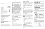
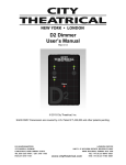
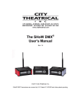
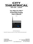
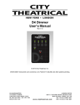
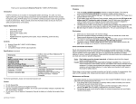
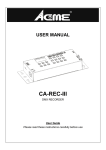
D3 Dimmer
User’s Manual
Rev. 4
© 2011, 2013 City Theatrical, Inc.
Contents
Figures .............................................................................................................................. 2 SYSTEM COMPLIANCE INFORMATION ........................................................................ 3 Safety Notices ................................................................................................................... 3 The D3 Dimmer User Interface ......................................................................................... 4 The D3 Dimmer ................................................................................................................. 5 Controls, Connections and Features ............................................................................. 5 Front Panel .................................................................................................................... 5 Back Panel .................................................................................................................... 5 Menu System................................................................................................................. 6 Menu:............................................................................................................................. 7 Addressing..................................................................................................................... 7 Level Tests .................................................................................................................... 7 Curve Selection ............................................................................................................. 7 RDM Basics ................................................................................................................... 7 Figures
Figure 1, D3 Dimmer Front Panel ..................................................................................... 4 Figure 2, the D3 Dimmer Channel Dimmer ....................................................................... 5 Figure 3, D3 Dimmer Menus ............................................................................................. 6 Page 2
SYSTEM COMPLIANCE INFORMATION
The D3 Dimmer is ETL and cETL Listed as follows:
• ETL Listed, Conforms to UL 508A
• cETL Listed, Certified to Can/CSA Standard 22.2 14-95
The D3 Dimmer is CE & FCC Certified
Standards Applied:
BS EN 60950-1:2002 incorporating Corrigendum No. 1 and Amendment No. 1
EN 55203-1: 1996
EN 55203-2: 1996
Product Conforms to CE Marking Directive 93/68/EEC
All D3 Dimmer models are RoHS compliant
Safety Notices
Please read this entire manual before using your new equipment. Please keep the
manual in a safe place so you can refer to it in the future as required.
The D3 Dimmer is intended for use only by qualified professionals. Connection,
installation and hanging of this equipment must be performed in accordance with all
pertinent local, regional and national safety codes and regulations.
D3 Dimmer equipment is intended for indoor use only unless specified for outdoor use.
Keep the equipment dry! Do not operate the equipment if it gets wet!
Do not operate in excessive heat/direct sunlight.
Be sure installation provides adequate ventilation. Some system components can
produce significant heat and must be properly installed to allow proper cooling and
assure user safety (please see specific notes about D3 Dimmer installation and heat in
this manual). All sides of the equipment must be clear of obstruction and allow free
airflow.
Page 3
Introduction
Thank you for selecting City Theatrical’s Three Channel Dimmer!
Every effort has been made to anticipate your questions in this manual, but if you have
any questions that are not answered here, or you want to discuss a special application,
please feel free to contact us directly at City Theatrical. The D3 Dimmer includes a wide
range of products which you may review at our website (www.citytheatrical.com) or in
our catalog. For basic wireless operation, a minimum of one SHoW DMX Transmitter
and one SHoW DMX Receiver is required. D3 Dimmers are fully RDM/DMX compliant
wired devices and may also be used in conventional wired DMX or RDM/DMX systems.
The Three Channel 10A D3 Dimmer serves as a versatile lighting control module,
providing three channels of 9-12VDC incandescent ISL and Linear dimming, Non Dim
control, and RGB LED control in a single feature-packed unit.
BUTTON PAD
LCD DISPLAY
UP
L
E
F
T
ENT
R
I
G
H
T
DOWN
Figure 1, D3 Dimmer Front Panel
The D3 Dimmer User Interface
Press the Enter (center) Button to access the menus, and press the UP or Down Buttons
to move through the menus. When you reach a menu that you want to work in, press
Enter to select that menu and then use the UP or Down Buttons to move through that
menu’s options. To scroll through a menu’s selection options hold the Up or Down
button.
When you reach an option that you want to modify, press enter to select it. A blinking
cursor in the option line will appear. Use the UP and Down arrows to move through the
available options and use the Enter Button to select the option you want. If you have
selected a menu option to edit but don’t actually want to edit it, press and hold the Back
Button for 1 second to escape the edit command.
Once you have made the choices you want, simply press the back button to back out of
the menu level. Continue to press the back button to move back to the Main Menu. If
you want to back out of a particular selection at any time, press the Back Button.
Page 4
The D3 Dimmer
DMX Termination Switch
3x2 45A Anderson PowerPole
for Dimmer Outputs
Reset Switch
1x2 45A Anderson PowerPole
for DCV Input
LCD Display
5PXLRM for DMX/RDM Input
Control Button Pad
5PXLRF for DMX/RDM Pass Thru
5620 SHoW DMX 3 Channel DImmer
D3 Dimmer
Front
View
5620 SHoW DMX 3 Channel Dimmer
D3
Dimmer
Back
View
Front View
Back View
Figure 2, the D3 Dimmer
The D3 Dimmer was designed to provide exceptional power and flexibility in a low
voltage DC control unit. The D3 Dimmer can be configured as three separate 10A
dimmers, two 15A dimmers, or one 30A dimmer. It will operate with any DC voltage
between 9-12VDC. Each dimmer channel can be separately configured with any of four
different output profiles, including ICS curve dimming (for incandescent loads), linear
dimming, LED dimming, or Non-Dim operation. The unit may be configured either
locally via the Button pad and LCD user interface, or via RDM.
Controls, Connections and Features
Front Panel
LCD Display: This 2 line by 16 character display shows all of the Menu titles, command
options, configuration data, and other text and graphic data. The backlight turns on
whenever a button is pushed and turns off automatically after a preset time-out. The
backlight off time-out is adjustable via the Misc. Menu (see below).
UP
Control Button Pad: This five-button pad is the main control interface
for the D3 Dimmer. The button functions are UP, DOWN, LEFT/BACK,
RIGHT/FORWARD, and ENTER.
L
E
F
T
ENT
R
I
G
H
T
DOWN
During normal operation (default configuration), the Left, Down and Right Buttons serve
as Bump Buttons for the three dimmers in the unit.
Back Panel
Anderson 45A Power Pole DC Power Input Connectors (Red +/Black -): This is the
+VDC power input for the D3 Dimmer, and mates directly with the 30A and 45A
Anderson Power Pole connectors on the CTI # 5540 12V 12AH Batteries, CTI Anderson
Twofers, cable assemblies, and other devices. The D3 Dimmer is capable of drawing up
to 30 amps of DC power, so be sure that the connected input power wiring is up to the
task! Be sure the power connection is polarized correctly before connecting an
alternative supply.
Page 5
Anderson 45A Power Pole DC Power Dimmer Output Connectors (Yellow +/Blue -):
These are the +VDC dimmed outputs for the D3 Dimmer, and are labelled A, B and C.
They mate directly with the 30A and 45A Anderson Power Pole connectors on CTI
Anderson Twofers, cable assemblies, and other devices. Note that for each dimmer
channel the Blue – output is the pulse width modulated (PWM) output, while the Yellow
+ output is the constant power output. The D3 Dimmer is capable of outputting up to 30
amps of DC power, so be sure that the connected output power wiring is up to the task!
Reset Switch: This little recessed switch resets the Microcontroller in the D3 Dimmer.
Use a paper clip or other small object to press if required.
5P XLR Male Connector: DMX/RDM Input. Connect your DMX512 source here using
any ESTA compliance DMX512 cable.
5P XLR Female Connector: DMX/RDM Pass-Thru/Output. When the Transmitter is
connected to a conventional DMX controller, this connector serves as a DMX pass-thru.
DMX Termination Switch: The D3 Dimmer DMX Input is provided with a conventional
manual termination switch. Switch the handle to ON for end-of line DMX Termination.
Menu System
Addressing
DMX Start
DMX Personality
Level Tests
Dimmer A Level
Dimmer B Level
Dimmer C Level
Curve Selection
Dimmer Curve A
Dimmer Curve B
Dimmer Curve C
Misc. Settings
Bump Buttons
Data Loss T-Out
Backlight T-Out
Battery Voltage
RDM Label
RDM Unique ID
Input Status
Restore Defaults
Firmware Version
LED TV/Film Mode
LED Smoothing
Figure 3, D3 Dimmer Menus
After power-up the LCD display will read:
D3 Dimmer
DMX: No Data (or) OK
Page 6
The Start Up display reports DMX connection status (“DMX: OK” or “DMX: No Data”).
Press the center ENTER button to access the menus.
Menu:
Addressing
DMX Start: Set the Starting DMX address for the Dimmer
DMX Personality: Set the DMX Personality for the Dimmer as either Triple
Dimmer, Double Dimmer, or Single Dimmer
Level Tests
Dimmer A Level: Set Dimmer A to a Level in %
Dimmer B Level: Set Dimmer B to a Level in %
Dimmer C Level: Set Dimmer C to a Level in %
Curve Selection
Dimmer Curve A: Select either ISL, Linear, LED, or Non-Dim.
Dimmer Curve B: Select either ISL, Linear, LED, or Non-Dim.
Dimmer Curve C: Select either ISL, Linear, LED, or Non-Dim.
The ISL and Linear curves are optimized for incandescent loads, and the LED
curve is optimized for LEDs.
LED TV/Film Mode: Five options for LED (mode 3 by default).
LED Smoothing: Six different delay times to make LED dim at different rates;
5ms, 10ms, 50ms, 100ms, 200ms and 400ms (100ms smoothing by default).
Misc. Settings
Bump Buttons: Enables or Disables Bump Buttons
Data Loss T-Out: Adjust how long the last valid DMX level is held if DMX is lost,
from 5 minutes – 120 Minutes, plus infinity (5 min. by Default)
Backlight T-Out: Allows adjustment of the Backlight automatic shutoff time-out
from Always off, through 1-240 seconds on, to Always on (10s by Default)
Battery Voltage: Displays connected battery voltage
RDM Label: This is an editable field that allows the user to create a unique
alpha-numeric 16 character RDM label for the unit
RDM Unique ID: This is a non-editable field that displays the RDM Unique ID
Input Status: Displays input status as DMX OK or DMX No Data
Restore Defaults: Restores factory defaults as DMX start 1, Triple Dimmer, ISL
Curve on all, 10 sec. backlight time-out, 5 min. DMX data loss time-out
Firmware Version: Displays firmware version
RDM Basics
Remote Device Management over DMX512 Networks (RDM) has been developed by
PLASA as a communications and control protocol to allow devices to be remotely
managed via existing DMX512 wiring, and is basically a variation on DMX512. Further,
the protocol is defined to allow existing (“legacy”) DMX devices to be connected and
operate on the same link as RDM devices and operate normally. This can occur
because the RDM data signals are “mixed in” with conventional DMX data signals, and
while conventional legacy DMX devices cannot respond to or communicate via the RDM
data, they will continue to respond to the DMX portion of the data, while (hopefully)
ignoring the RDM portion (more on the “hopefully” later). The other big difference
between DMX and RDM is that DMX is a simplex or “one way” protocol, while RDM is a
half-duplex or “two way” protocol. DMX data always flows from the controller to the
controlled devices, while RDM can flow back and forth.
Page 7
A full length DMX512 packet includes 513 data bytes. For conventional DMX
communication, the first byte should consist of all 0s, while the remaining 512 bytes
contain the data intended to control the 512 DMX devices connected to the link. That
first byte has been referred to variously as the Start Code, Null Byte, 0 Byte, etc. RDM
data looks very much the same as DMX data, except that the packet length can vary
with each communication, the longest packet is 257 bytes, and the first byte contains
different data than all 0s. The data in that first byte identifies the packet as an RDM
rater than DMX packet.
An RDM system consists of a controller and one or more responders. These units will
normally be operating as a conventional DMX network. When RDM control activity is
needed, the controller will issue a special RDM data command to alert any connected
RDM devices, and then may issue any of a variety of other RDM commands to trigger
actions or responses in the connected responders (dimmers, fog machines, whatever).
As mentioned above, the RDM data is mixed in with conventional DMX data and in
theory should be invisible to conventional DMX devices on the link.
An RDM session must begin with RDM Discovery, during which the controller identifies
and builds a list of all the connected RDM responders connected to its data link. Once
the controller has discovered all of the connected responders, they can be monitored,
adjusted, configured and generally managed individually over the RDM data link. During
normal RDM operations, the Discovery process is periodically repeated so that added,
removed, or failed devices can be identified and the controller’s list can be updated.
There are a few caveats that should be understood when working with RDM.
•
RDM data replaces DMX data, and so reduces the resolution of the DMX data
stream, particularly when lengthy, complex operations like Discovery are
occurring. This loss of resolution can affect the performance of sensitive DMX
and RDM controlled devices (like LED fixtures) and can even make the whole
system pause or appear sluggish while the RDM operation is occurring.
•
Some conventional DMX devices ignore RDM start codes. Although for many
years, the DMX512 Standard has required DMX devices to not respond
incorrectly to data packets with alternate (non-0) start codes, there are units out
there that completely disregard the start code, which means they will do some
strange things when presented with RDM data.
For these reasons, we recommended that RDM users test their system well in advance
of show time to identify any non-compliant DMX devices that might flip out during RDM
operations, and so that operators can experience the loss of resolution that occurs
during RDM operations and decide if they should limit RDM sessions to non-critical
periods, such as during the pre-show checkout.
Page 8