1
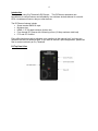
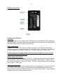
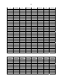
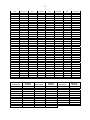
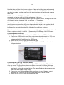
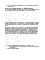
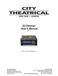
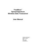
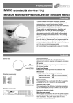
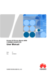
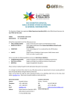
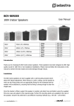
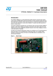
D2 Dimmer
User’s Manual
Rev 0.13
© 2013 City Theatrical, Inc.
SHoW DMX Transceivers are covered by U.S. Patent # 7,432,803 and other patents pending.
2
System Compliance Information (pending) ...................................................................... 3
Safety Notices, Ratings and Power Requirements ........................................................... 3
Introduction .......................................................................................................................... 4
D2 Top Panel View ............................................................................................................... 4
D2 Bottom Panel View ......................................................................................................... 5
Setting up the D2 Dimmer ...................................................................................................... 5
Installation ............................................................................................................................ 5
Power Connections ............................................................................................................. 5
Dimmer Output Connections .............................................................................................. 5
Over-current Protection ...................................................................................................... 5
Wired DMX512 Input ............................................................................................................ 6
User interface ....................................................................................................................... 6
D2 Dimmer RDM Parameter IDs ......................................................................................... 7
Dimmer Configuration ......................................................................................................... 7
DMX addressing................................................................................................................... 8
Selecting Dimmer Curves ................................................................................................... 8
Using D Series Dimmers with CTI Flicker Candles .......................................................... 9
Appendix A: DMX512 Starting Address DIP Switch Tables ............................................... 9
Appendix B: Using D series Dimmers with LED Tape ..................................................... 12
How much Tape can I use with one D2 Dimmer? ........................................................... 12
Connecting Single Color Tape ......................................................................................... 13
Connecting Two Color (e.g. Cool/Warm White) .............................................................. 13
Adapted from City Theatrical Tech Bulletin 1003: Working with LED Tape ................. 14
D2 Dimmer Specifications .................................................................................................... 15
3
System Compliance Information (pending)
This product is in review and has not yet been fully certified
The D2 Dimmer is CE Certified
Standards applied:
EN 55203-1: 2009
EN 55203-2: 2009
EN 301 489-1 V1.8.1
EN 301 489-3 V1.4.1
EN 60950-1:2006 / A1:2010
FCC Rules, Part 15, Subpart B, Sections 15.107 and 15.109
Products Conform to CE Marking Directive 93/68/EEC
All models are RoHS compliant
Safety Notices, Ratings and Power Requirements
Please read this entire manual before using your new equipment. Please keep the manual in a safe
place so you can refer to it in the future as required.
The D2 Dimmer is intended for use only by qualified professionals. Connection, installation and hanging
of this equipment must be performed in accordance with all pertinent local, regional and national safety
codes and regulations.
The D2 Dimmer is intended for indoor use.
The unit enclosure is rated NEMA 1 / IP20.
Rated operating voltage; 7.5-30VDC, 10A max
Maximum operating temperature: 0°C - 40°C.
4
Introduction
Thank you for using City Theatrical’s D2 Dimmer. The D2 Dimmer represents new
benchmarks for control features and affordability in a miniature wireless dimmer for use with
LEDs, incandescent fixtures, relays or other devices.
The D2 Dimmer features include:
• Screw terminal DMX512 Input
• Miniature size
• NEMA 1 / IP 20 rated enclosure (indoor use)
• Four channel DC Dimmer with 4 dimming curves (10 Amp maximum total load)
• FCC and CE Certified
Every effort has been made to anticipate your questions in this manual, but if you have any
questions that are not answered here, or you want to discuss a special application, please feel
free to contact us directly at City Theatrical.
.
D2 Top Panel View
5
D2 Bottom Panel View
Setting up the D2 Dimmer
Installation
Install the D2 Dimmer in a suitable location, following the instructions below. When selecting a
mounting location, note that for best results the antennas in your system must be within sight of
each other and polarized the same way (see below).
Power Connections
Connect +7.5 ~ 30VDC DC Power to the Dimmer using the two provided screw terminals.
Connect +VDC to the + (plus) Terminal and – (minus) VDC to the – Terminal. These terminals
will accommodate up to 14 AWG / 1.5mm2 wire. This DC power input is rated for 10A.
Be aware that the power supply voltage must match the rated voltage of the load. If you are
using 12V LED tape, use 12VDC power.
Dimmer Output Connections
The two dimmer channels are labeled “A” and “B”. Connect the load wiring using the provided
screw terminals. There is a screw terminal pair provided for each dimmer. Connect +VDC to
the + (plus) Terminal and – (minus) VDC to the – Terminal. These terminals will accommodate
up to 14 AWG / 1.5mm2 wire.
Over-current Protection
The D2 Dimmer is provided with an internal 25A fuse for input protection. This fuse is not user
service-able. Each dimmer output is provided with fuse-less hardware-based over-current
protection that functions automatically when an over-current condition exists. When overload
condition is removed, normal operation resumes.
6
Wired DMX512 Input
This is a PLASA/ANSI compliant DMX512-A Input. You may connect this Input in a daisy chain
to additional down-stream DMX512 devices using suitable cable such as Cat5 UTP or approved
DMX512 Cable. Short runs may be connected with neatly twisted 24AWG hookup wire. A
single position DIP switch is provided as a DMX termination switch if the unit is at the end of the
DMX line. The Termination switch is located at the far right of the DMX Address DIP Switch
array and is marked “T”.
The DMX512 Input is labeled Com, D- and D+, corresponding to standard DMX512 connections
of Common, Data – and Data +. You can build an XLR or RJ45 cable adapter using the table
below, which shows connection to 5 pin and 3 pin XLR and RJ45 connectors:
Common Data ‐ D Series Terminal COM D‐ 5 Pin XLR Female Pin 1 Pin 2 3 Pin XLR Female Pin 1 Pin 2 Data + D+ Pin 3 Pin 3 Signal RJ45 Pin 7 (white/brown) Pin 2 (orange) Pin 1 (white / orange) Note that as this is an input, the XLR connector should normally be male.
User interface
The D2 Dimmer is provided with a set of switches and LED indicators for configuration and
status monitoring:
(Top Panel)
1. DMX Present LED: Indicates DMX512 Data is being received
2. Dimmer Pilot Light LEDs: Fade up and down with the dimmer to permit easy monitoring
and testing
3. Status LED: Indicates the following error/fault conditions:
Condition
UNDER VOLTAGE INVALID DMX ADDRESS
INVALID SHOW ID
OUTPUT OVER CURRENT
INPUT OVER CURRENT
OVER TEMP
OVER VOLTAGE
. . . .. .. .. … … … Blinks followed by 1sec pause 1 2 3 …. …. …. 4 ….. ….. ….. …… …… …… ……. ……. ……. 5 6 7 Blink Pattern 4. Bump Buttons: A bump button is provided for each dimmer output
(Bottom Panel)
5. DMX Addressing DIP Switch (9 position): Set the starting DMX address for the unit
6. Curve Selection DIP Switch (4 position): Select the dimming curve for each of the
individual dimmer outputs in the unit
7
7. MOD Selection DIP Switch (2 position): Select the PWM modulation frequency for
dimmer channels set to the LED Curve.
8. R DIP Switch (1 position): Setting this Reset switch to ON resets the Dimmer and holds
in reset until set to OFF.
9. T Dip Switch (1 position): Setting this termination switch to ON connects end-of-line
DMX termination.
D2 Dimmer RDM Parameter IDs
The D2 Dimmer supports the all mandatory RDM Parameter IDs (PIDs) plus to following PIDs:
PROXIED_DEVICE_COUNT
PROXIED_DEVICES_ENHANCED
SUPPORTED_PARAMETERS
PARAMETER_DESCRIPTION
DEVICE_MODEL_DESCRIPTION
MANUFACTURER_LABEL
DEVICE_LABEL
FACTORY_DEFAULTS
SOFTWARE_VERSION_LABEL
DMX_BLOCK_ADDRESS
SENSOR_DEFINITION
SENSOR_VALUE
RECORD_SENSORS
OUTPUT_RESPONSE_TIME
OUTPUT_RESPONSE_TIME_DESCRIPTION
MODULATION_FREQUENCY
MODULATION_FREQUENCY_DESCRIPTION
DMX_START_ADDRESS
SLOT_INFO
SLOT_DESCRIPTION
SENSOR_DEFINITION
SENSOR_VALUE
RECORD_SENSORS
CURVE
CURVE_DESCRIPTION
IDENTIFY_DEVICE
To learn more about RDM, a good place to start is the Wikipedia article on RDM (lighting) at:
http://en.wikipedia.org/wiki/RDM_(lighting)
Dimmer Configuration
The D2 Dimmer has two independent Pulse Width Modulated (PWM) VDC dimmer outputs.
Each output responds to a separate DMX512 slot; these slots are addressed contiguously with
the first slot being the Starting Address. Each output can be configured individually with one of
three dimming curves or as a NON-DIM.
8
DMX addressing
Set the starting address for the D2 Dimmer using the DMX Address DIP switch. The nine
switch positions set the starting DMX address (this is a binary value). A complete DMX Starting
Address DIP Switch Table is provided in Appendix A.
DMX addressing may be set manually using the DMX Starting Address DIP switches or using
RDM. When RDM is used, the individual dimmer channels may be set independently to any
DMX address. When the DIP switched are used, the channels are addressed contiguously form
the base address set by the switch. The highest address that can be set by the DIP switch is
limited to 509 in the D2 Dimmer and 511 in the D2 Dimmer.
Whichever method is used last takes precedence. The unit maintains the last used setting over
power cycles, and checks on power up to see if switches have been changed while the unit was
off.
Selecting Dimmer Curves
The dimming curve can be set individually for each 5A Dimmer output. The SHoW DMX Neo
D2 Dimmer has an eight position DIP Switch with two positions for each dimmer output.
Dimmer
A
B
Switch Switch Switch
1
2
3
Switch
4
Function
OFF
OFF
Normal Dimming, ISL Curve
OFF
ON
NON - DIM
ON
OFF
Linear Dimming Curve
ON
ON
LED Curve
OFF
OFF
Normal Dimming, ISL Curve
OFF
ON
NON - DIM
ON
OFF
Linear Dimming Curve
ON
ON
LED Curve
The ISL (Inverse Square Law) Curve is intended for incandescent lamp dimming and is similar
to a conventional mains-powered lighting dimmer curve. The PWM period for ISL is 60Hz.
The NON-DIM function is intended for relays and other devices requiring switched power
without PWM dimming.
The Linear Curve is a simple linear scale that can be used to drive DC integrators or other
devices where linear response needed. The Linear PWM period is 60Hz.
The LED Curve is intended for controlling LEDs but may be used for other specialized loads.
The LED Curve Modes have been optimized for flicker free performance in TV and Film
applications. All settings have been camera tested with motion picture film and digital cameras.
The settings are different to allow compensation for variations in shutter speed and shutter
angle. A camera test is recommended to confirm the correct setting has been selected.
The Mode Settings include TV/Film Mode 1 - 4 which are DIP selectable, and TV/Film Mode 5
which is selectable via RDM only using the MODULATION_FREQUENCY RDM parameter.
9
The SHoW DMX Neo D2 Dimmer has a two position DIP switch for setting the TV/Film Mode:
OFF
OFF
TV/Film Mode 1
ON
OFF
TV/Film Mode 2
OFF
ON
TV/Film Mode 3
ON
ON
TV/Film Mode 4
The settings are also provided to allow control of other specialized loads (see below).
Dimmer curves and Modes may be set manually using the Dimmer Curve and Mode DIP
switches or using RDM. Whichever method is used last takes precedence. The unit maintains
the last used setting over power cycles, and checks on power up to see if switches have been
changed while the unit was off.
Using D Series Dimmers with CTI Flicker Candles
City Theatrical Flicker Candles may be used with the D Series Dimmers in TV/Film Mode 4 or 5
without need for a candle adapter. Up to 50 CTI Flicker candles can be powered and dimmed
with a D Series Dimmer.
The D2 Dimmer is a constant voltage PWM dimmer and so will work with any size LED load that
is within the Dimmer’s 5A current and 7.5-30VDC voltage range. Note that constant voltage
dimmers do not compensate for voltage drop in load wiring so care should be taken to optimize
load wiring designs by minimizing run length, assuring termination quality, and assuring
adequately sized wire is used.
Dimmer curves may be set manually using the Dimmer Curve DIP switches or using RDM.
Whichever method is used last takes precedence. The unit maintains the last used setting over
power cycles, and checks on power up to see if switches have been changed while the unit was
off.
Appendix A: DMX512 Starting Address DIP Switch Tables
Start
Address
1
2
3
4
5
6
7
8
9
10
11
12
13
DIP Setting
123456789
100000000
010000000
110000000
001000000
101000000
011000000
111000000
000100000
100100000
010100000
110100000
001100000
101100000
Start
Address
51
52
53
54
55
56
57
58
59
60
61
62
63
DIP Setting
123456789
110011000
001011000
101011000
011011000
111011000
000111000
100111000
010111000
110111000
001111000
101111000
011111000
111111000
Start
Address
101
102
103
104
105
106
107
108
109
110
111
112
113
DIP Setting
123456789
101001100
011001100
111001100
000101100
100101100
010101100
110101100
001101100
101101100
011101100
111101100
000011100
100011100
Start
Address
151
152
153
154
155
156
157
158
159
160
161
162
163
DIP Setting
123456789
111010010
000110010
100110010
010110010
110110010
001110010
101110010
011110010
111110010
000001010
100001010
010001010
110001010
10
14
15
16
17
18
19
20
21
22
23
24
25
26
27
28
29
30
31
32
33
34
35
36
37
38
39
40
41
42
43
44
45
46
47
48
49
50
011100000
111100000
000010000
100010000
010010000
110010000
001010000
101010000
011010000
111010000
000110000
100110000
010110000
110110000
001110000
101110000
011110000
111110000
000001000
100001000
010001000
110001000
001001000
101001000
011001000
111001000
000101000
100101000
010101000
110101000
001101000
101101000
011101000
111101000
000011000
100011000
010011000
64
65
66
67
68
69
70
71
72
73
74
75
76
77
78
79
80
81
82
83
84
85
86
87
88
89
90
91
92
93
94
95
96
97
98
99
100
000000100
100000100
010000100
110000100
001000100
101000100
011000100
111000100
000100100
100100100
010100100
110100100
001100100
101100100
011100100
111100100
000010100
100010100
010010100
110010100
001010100
101010100
011010100
111010100
000110100
100110100
010110100
110110100
001110100
101110100
011110100
111110100
000001100
100001100
010001100
110001100
001001100
114
115
116
117
118
119
120
121
122
123
124
125
126
127
128
129
130
131
132
133
134
135
136
137
138
139
140
141
142
143
144
145
146
147
148
149
150
010011100
110011100
001011100
101011100
011011100
111011100
000111100
100111100
010111100
110111100
001111100
101111100
011111100
111111100
000000010
100000010
010000010
110000010
001000010
101000010
011000010
111000010
000100010
100100010
010100010
110100010
001100010
101100010
011100010
111100010
000010010
100010010
010010010
110010010
001010010
101010010
011010010
164
165
166
167
168
169
170
171
172
173
174
175
176
177
178
179
180
181
182
183
184
185
186
187
188
189
190
191
192
193
194
195
196
197
198
199
200
001001010
101001010
011001010
111001010
000101010
100101010
010101010
110101010
001101010
101101010
011101010
111101010
000011010
100011010
010011010
110011010
001011010
101011010
011011010
111011010
000111010
100111010
010111010
110111010
001111010
101111010
011111010
111111010
000000110
100000110
011000010
110000110
001000110
101000110
011000110
111000110
000100110
Start
Address
201
202
203
204
205
206
207
208
209
210
211
212
DIP Setting
123456789
100100110
010100110
110100110
001100110
101100110
011100110
111100110
000010110
100010110
010010110
110010110
001010110
Start
Address
251
252
253
254
255
256
257
258
259
260
261
262
DIP Setting
123456789
110111110
101111110
101111110
011111110
111111110
000000001
100000001
010000001
110000001
001000001
101000001
011000001
Start
Address
301
302
303
304
305
306
307
308
309
310
311
312
DIP Setting
123456789
101101001
011101001
111101001
000011001
100011001
010011001
110011001
001011001
101011001
011011001
111011001
000111001
Start
Address
351
352
353
354
355
356
357
358
359
360
361
362
DIP Setting
123456789
111110101
000001101
100001101
010001101
110001101
001001101
101001101
011001101
111001101
000101101
100101101
010101101
11
213
214
215
216
217
218
219
220
221
222
223
224
225
226
227
228
229
230
231
232
233
234
235
236
237
238
239
240
241
242
243
244
245
246
247
248
249
250
Start Address
401
402
403
404
405
406
407
408
409
410
411
412
101010110
011010110
111010110
000110110
100110110
010110110
110110110
001110110
101110110
011110110
111110110
000001110
100001110
010001110
110001110
001001110
101001110
011001110
111001110
000101110
100101110
010101110
110101110
001101110
101101110
011101110
111101110
000011110
100011110
010011110
110011110
001011110
101011110
011011110
111011110
000111110
100111110
010111110
DIP Setting
123456789
100010011
010010011
110010011
001010011
101010011
011010011
111010011
000110011
100110011
010110011
110110011
001110011
263
264
265
266
267
268
269
270
271
272
273
274
275
276
277
278
279
280
281
282
283
284
285
286
287
288
289
290
291
292
293
294
295
296
297
298
299
300
111000001
000100001
100100001
010100001
11100001
001100001
101100001
011100001
111100001
000010001
100010001
010010001
110010001
001010001
101010001
011010001
111010001
000110001
100110001
010110001
110110001
001110001
101110001
011110001
111110001
000001001
100001001
010001001
110001001
001001001
101001001
011001001
111001001
000101001
100101001
010101001
110101001
001101001
Start Address
451
452
453
454
455
456
457
458
459
460
461
462
313
314
315
316
317
318
319
320
321
322
323
324
325
326
327
328
329
330
331
332
333
334
335
336
337
338
339
340
341
342
343
344
345
346
347
348
349
350
DIP Setting
123456789
110000111
001000111
101000111
011000111
111000111
000100111
100100111
010100111
110100111
001100111
101100111
011100111
100111001
010111001
110111001
001111001
101111001
011111001
111111001
000000101
100000101
010000101
110000101
001000101
101000101
011000101
111000101
000100101
100100101
010100101
110100101
001100101
101100101
011100101
111100101
000010101
100010101
010010101
110010101
001010101
101010101
011010101
111010101
000110101
100110101
010110101
110110101
001110101
101110101
011110101
363
364
365
366
367
368
369
370
371
372
373
374
375
376
377
378
379
380
381
382
383
384
385
386
387
388
389
390
391
392
393
394
395
396
397
398
399
400
Start Address
501
502
503
504
505
506
507
508
509
510
511
110101101
001101101
101101101
011101101
111101101
000011101
100011101
010011101
110011101
001011101
101011101
011011101
111011101
000111101
100111101
010111101
110111101
001111101
101111101
011111101
111111101
000000011
100000011
010000011
110000011
001000011
101000011
011000011
111000011
000100011
100100011
010100011
110100011
001100011
101100011
011100011
111100011
000010011
DIP Setting
123456789
101011111
011011111
111011111
000111111
100111111
010111111
110111111
001111111
101111111
011111111
111111111
12
413
414
415
416
417
418
419
420
421
422
423
424
425
426
427
428
429
430
431
432
433
434
435
436
437
438
439
440
441
442
443
444
445
446
447
448
449
450
101110011
011110011
111110011
000001011
100001011
010001011
110001011
001001011
101001011
011001011
111001011
000101011
100101011
010101011
110101011
001101011
101101011
011101011
111101011
000011011
100011011
010011011
110011011
001011011
101011011
011011011
111011011
000111011
100111011
010111011
110111011
001111011
101111011
011111011
111111011
000000111
100000111
010000111
463
464
465
466
467
468
469
470
471
472
473
474
475
476
477
478
479
480
481
482
483
484
485
486
487
488
489
490
491
492
493
494
495
496
497
498
499
500
111100111
000010111
100010111
010010111
110010111
001010111
101010111
011010111
111010111
000110111
100110111
010110111
110110111
001110111
101110111
011110111
111110111
000001111
100001111
010001111
110001111
001001111
101001111
011001111
111001111
000101111
100101111
010101111
110101111
001101111
101101111
011101111
111101111
000011111
100011111
010011111
110011111
001011111
Appendix B: Using D series Dimmers with LED Tape
The CTI 5700 D series Dimmers have been optimized for use with LED tape. The D2 Dimmer
can be used to run up to two strips of single color tape, or one strip of two color tape. A D2 and
D4 Dimmer can be combined to run two strips of three color tape.
How much Tape can I use with one D2 Dimmer?
LED tape load current varies by brand and style. Among 3/8” / 10mm wide tape styles with a
single row of LEDs, single color tape is available that draws between 60mA to 99mA per foot,
and RGB (three color) tape is available that draws between 124mA and 336mA per foot. LED
products are constantly evolving, so be sure and check the tape you are using to confirm the
load per foot/color. Remember that the ampacity of the tape can vary, so if you approach the
Dimmer’s maximum load limit, check that actual load carefully to confirm that you haven’t
exceeded the limit.
13
Note that there are limits to how long a single run of tape can be before tape performance is
degraded, and this limit may not be equal to the maximum load the D2 Dimmer will drive. For
very long runs of tape, you may need to cut the tape into pieces and feed them via separate
home runs.
For 200mA two color C/W White tape, CTI recommends a maximum of 48 feet of tape be
connected, and that you split this load into at least two 24 foot runs.
If you connect 48 feet of this 200mA per foot tape to a single D2 dimmer, resulting in a total load
of 9.6A and a load per channel of 4.8A, you will have ~ 4 % head room.
Most manufacturers offer their longest tape in reels of ~ 16 feet/ 5 Meters, and some
manufacturers recommend that single runs of tape should be limited to no more than the full
length of the manufacturers reel. With some brands you may still notice a difference in
brightness from one end to the other if the full reel is connected as a single run.
Remember that that the power supply voltage must match the rated voltage of the load. The D2
Dimmer outputs the voltage it receives. If you are using 12V LED tape, use 12VDC power.
Connecting Single Color Tape
12 Volt single color tape is provided with a single +VDC circuit and a –VDC circuit.
1. Connect the +VDC circuit to one of the + output terminals and connect the -VDC circuit
to the accompanying –output terminal. Up to two runs of single color tape can be
independently driven and dimmed by a D2 Dimmer.
2. Select the LED Curve for each dimmer channel used.
3. If you wish to change the PWM frequency, use RDM or the MOD switch to select the
frequency desired.
Connecting Two Color (e.g. Cool/Warm White)
12 Volt two color LED tape is provided with a single +12VDC circuit and a –VDC circuit for each
of the two colors. The photo above shows connection of two color Cool/Warm White tape.
1. Connect the +12VDC circuit to any one of the two + output terminals. The + terminals
are bussed, and provide constant voltage. The tape in the photo above was pre-wired
with Brown wire for the +12VDC circuit.
2. Connect the Cool White and Warm White circuits each to one of the two – output
terminals. The – terminals are the PWM dimmed outputs of the D2 Dimmer.
3. Select the LED Curve for each dimmer channel used.
14
4. If you wish to change the PWM frequency, use RDM or the MOD switch to select the
frequency desired.
Adapted from City Theatrical Tech Bulletin 1003: Working with LED Tape
The structure and electrical properties of LED Tape pose some important challenges to system
designers and production electricians that must be met to insure good performance.
1.
2.
3.
4.
5.
Locate Dimmers as close to the connection end of the tape as possible
Be aware of all run length limitations and meet them or devise de-rated alternatives
Use the heaviest wire possible for long Line and Load connection wiring
Check all terminations to confirm they are tight and correctly formed
Minimize wire transitions and terminations whenever possible
LED Tape typically consists of a strip of flexible printed circuit board material, backed with peeland-stick adhesive and populated with multiple LEDs (each with individual current-limiting
resistors) wired in parallel. Single color tape has one +VDC buss trace and one –VDC buss
trace. RGB Tape has one –VDC buss for each LED color and one common +VDC buss.
The copper in these buss traces must be adequate to carry the current needed for the maximum
allowable run length of the tape, while staying as small as possible. It is important to note that
the copper in the LED tape also serves as the heat sink for the LEDs and their current limiting
resistors.
If the maximum run length of the tape is exceeded, the copper busses will be overloaded and
will heat up more than they are supposed to. In the long run, this will defeat the heat-sinking
function and so fatigue the mounted components. In the short run, the heat will raise the
impedance of the copper and contribute to operating problems. Heat stressed-copper can
increase in impedance permanently. As the copper is heat-corrupted, the added impedance
increases the heat generated and the copper is damaged further, which increases the heat,
which increases the impedance, which increases the heat, which increases the impedance,…
Exceeding tape run length with single color LED tape can result in the following problems:
1. Excessive heat from the overloaded busses on the tape
2. Heat based component failure
3. Loss of output
4. Difference in brightness between the beginning and the end of the Tape
5. Permanent damage of the tape
Exceeding Tape run length with RGB LED tape can result in the following problems:
6. Excessive heat from the overloaded busses on the tape
7. Heat based component failure
8. Loss of output
9. Difference in brightness between the beginning and the end of the Tape
a. Interaction between the R,G and B Channels, resulting in flickering or strobing at
dimmed levels
10. Permanent damage of the tape
15
D2 Dimmer Specifications
DMX Control Features
• 3P Screw Terminals for DMX Input
• Termination switch for end-of line DMX termination
Other Features
• Four dimmer output channels
• Max output per dimmer channel 5A
• Max total output per device 10A
• Screw terminal connections for power input and dimmed output
• Each channel individually protected against over-current
• Each channel individually protected against over-temperature
• PWM resolution 16-bit
• Dimming Curves
o Linear, 60Hz
o ISL, 60Hz
o Non-Dim
o LED
• LED Features:
o Five variable LED smoothing rates
o Four Film and Video Modes
• Individual DMX addresses
• Fully RDM enabled
Mechanical
• NEMA 1 ABS enclosure
Electronic/ Functional Features
• Individual Bump Buttons
• DIP Switch, DMX Addressing (9POS)
• DIP Switch, Curve Selection (4POS)
• DIP Switch, LED Curve PWM Frequency Selection (2POS)
• DIP Switch, DMX Termination (1POS)
• DIP Switch, Reset (1POS)
• LED indicators:
o Dimmer pilot lights (one for each channel)
o Data (data present)
o Status
Compliance:
• RoHS Compliant
• CE Pending
• FCC Pending
CTI Part #s: 5720 D2 Dimmer
16
Power: 7.5-30VDC 10A Max Power Input
Weight: 0.15 lbs/.08Kg
Dimensions: 2.25”/57mm W x3.5”/60mmH x 0.56”/14mmD (excluding antenna)