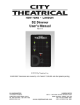
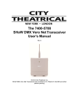
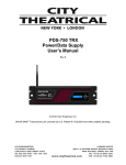
1
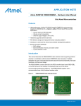
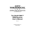
SHoW DMX Neo® D4 Dimmer User’s Manual Rev 0.12 © 2013 City Theatrical, Inc. SHoW DMX Transceivers are covered by U.S. Patent # 7,432,803 and other patents pending. 2 Radio Compliance Information ........................................................................................... 4 Antennas .............................................................................................................................. 5 5792 FCC/IC Approved Antennas ....................................................................................... 5 5792 CE Approved Antennas .............................................................................................. 6 The 5792 SHoW DMX Neo Radio Module CE Declaration of Conformity ....................... 7 System Compliance Information (pending) ...................................................................... 8 Safety Notices, Ratings and Power Requirements ........................................................... 8 Introduction .......................................................................................................................... 9 SHoW DMX Neo D4 Top Panel View ................................................................................ 10 SHoW DMX Neo D4 Bottom Panel View .......................................................................... 10 Setting up the SHoW DMX Neo D4 Dimmer .................................................................... 11 Installation .......................................................................................................................... 11 Power Connections ........................................................................................................... 11 Dimmer Output Connections ............................................................................................ 11 Over-current Protection .................................................................................................... 11 Wired DMX512 Output ....................................................................................................... 11 Antenna Setup ................................................................................................................... 12 User interface ..................................................................................................................... 12 Wireless DMX Configuration ................................................................................................ 13 SHoW ID .............................................................................................................................. 13 Neo Mode Operation .......................................................................................................... 13 Neo SHoW ID Table ........................................................................................................... 14 Neo Adaptive Mode Operation ......................................................................................... 15 Neo Adaptive SHoW ID Table ........................................................................................... 16 Adjustable Output Power .................................................................................................. 16 Limited Bandwidth mode .................................................................................................. 16 Limited Burst DMX Output ................................................................................................ 16 RDM Operation ................................................................................................................... 17 SHoW DMX Neo D4 Dimmer RDM Parameter IDs ........................................................... 17 Dimmer Configuration ....................................................................................................... 18 DMX addressing................................................................................................................. 18 Selecting Dimmer Curves ................................................................................................. 19 Using D Series Dimmers with CTI Flicker Candles ........................................................ 20 Loading and Voltage Drop ................................................................................................ 20 Appendix A: DMX512 Starting Address DIP Switch Tables ............................................. 21 Appendix B: Using D series Dimmers with LED Tape ..................................................... 24 3 How much Tape can I use with one D4 Dimmer? ........................................................... 24 Connecting Single Color Tape ......................................................................................... 24 Connecting Three Color (RGB) or Four Color (RGBW, RGBA) LED Tape.................... 25 Adapted from City Theatrical Tech Bulletin 1003: Working with LED Tape ................. 25 SHoW DMX Neo D4 Dimmer Specifications ........................................................................ 27 4 Radio Compliance Information 5792 SHoW DMX Neo Radio Transceiver FCC ID: VU65792 IC ID: 7480A5792 FCC Part 15 This equipment has been tested and found to comply with the limits for a Class B digital device, pursuant to part 15 of the FCC Rules. These limits are designed to provide reasonable protection against harmful interference in a residential installation. This equipment generates, uses and can radiate radio frequency energy and, if not installed and used in accordance with the instructions, may cause harmful interference to radio communications. However, there is no guarantee that interference will not occur in a particular installation. If this equipment does cause harmful interference to radio or television reception, which can be determined by turning the equipment off and on, the user is encouraged to try to correct the interference by one or more of the following measures: • Reorient or relocate the receiving antenna. • Increase the separation between the equipment and receiver. • Connect the equipment into an outlet on a circuit different from that to which the receiver is connected. • Consult the dealer or an experienced radio/ TV technician for help. Radio Frequency Notifications FCC Notifications RF Radiation The Product is an intentional radiator of Radio Frequency (RF) energy. In order to limit RF exposure to personnel in the immediate area, the Product should be located and installed such that a separation of at least 20 centimeters is maintained between the Product’s antenna and personnel in the vicinity of the device. Modification Warning Caution: changes or modifications to this equipment, not expressly approved by City Theatrical Inc. could void the user’s authority to operate the equipment. Industry Canada Notifications This Class B digital apparatus complies with Canadian ICES-003. Operation is subject to the following two conditions: (1) this device may not cause interference, and (2) this device must accept any interference, including interference that may cause undesired operation of the device. Cet appareil numérique de la classe B est conforme à la norme NMB-003 du Canada. Product Installation and Configuration Guide © City Theatrical Inc. 2007 5792 Approved Antenna To reduce potential radio interference to other users, the antenna type and its gain should be so chosen that the equivalent isotropically radiated power (e.i.r.p.) is not more than that permitted for successful communication. This device has been designed to operate with the antennas listed below. Antennas not included in this list or having a gain greater than 5 dB are strictly prohibited for use with this device. The required antenna impedance is 50 ohms. City Theatrical Inc. declares that this product conforms to the specifications listed in this manual, following the provisions of the European R&TTE directive 1999/5/EC: City Theatrical Inc. vakuuttaa täten että dieses produkt tyyppinen laite on direktiivin 1999/5/EY oleellisten vaatimusten ja sitä koskevien näiden direktiivien muiden ehtojen mukainen. City Theatrical Inc. déclare que le produit est conforme aux conditions essentielles et aux dispositions relatives à la directive 1999/5/EC. • EN 301 489-1, 301 489-17 General EMC requirements for Radio equipment. 5 • EN 60950 Safety • EN 300 328 Technical requirements for Radio equipment. CAUTION—This equipment is intended to be used in all EU and EFTA countries. Outdoor use may be restricted to certain frequencies and/or may require a license for operation. Contact local Authority for procedure to follow. Note: ESD precautions should be used when attaching or removing the antenna. Note: Combinations of power levels and antennas resulting in a radiated power level of above 100 mW equivalent isotropic radiated power (EIRP) are considered as not compliant with the above mentioned directive and are not allowed for use within the European community and countries that have adopted the European R&TTE directive 1999/5/EC. For more details on legal combinations of power levels and antennas, contact City Theatrical Inc. Do not use this product near water, for example, in a wet basement or near a swimming pool. Avoid using this product during an electrical storm. There may be a remote risk of electric shock from lightning. Product Installation and Configuration Guide © City Theatrical Inc. 2013 Q52 Regulatory information Radio Frequency Notifications Belgique Dans le cas d'une utilisation privée, à l'extérieur d'un bâtiment, au-dessus d'un espace public, aucun enregistrement n'est nécessaire pour une distance de moins de 300m. Pour une distance supérieure à 300m un enregistrement auprès de l'IBPT est requise. Pour une utilisation publique à l'extérieur de bâtiments, une licence de l'IBPT est requise. Pour les enregistrements et licences, veuillez contacter l'IBPT. France 2.4 GHz Bande : les canaux 10, 11, 12, 13 (2457, 2462, 2467, et 2472 MHz respectivement) sont complétement libres d'utilisation en France (en utilisation intérieur). Pour ce qui est des autres canaux, ils peuvent être soumis à autorisation selon le départment. L'utilisation en extérieur est soumis à autorisation préalable et très restreint. Vous pouvez contacter l'Autorité de Régulation des Télécommunications (http://www.art-telecom.fr) pour de plus amples renseignements. Antennas The SHoW DMX Neo D4 Dimmer is provided standard with a fixed (non-removable) antenna, which would normally not be replaced. In the event that custom or modified units are provided with removable antennas, the following information will apply. The model: 5792 can be configured with any one of the approved antennas listed below for fixed, point-to point one server and one client configuration. When the model: 5792 is configured for point-to-multipoint one server and multiple clients’ configuration (client’s talk to server only one at a time), client’s can use any of the approved antennas listed below and the server can use any of the approved antennas listed below with the exception of the 14dBi antenna. 5792 FCC/IC Approved Antennas Manufacturer Model Type Connector Gain Nearson S151AH-2450S Omni whip SMA plug reverse polarity 5dBi Nearson S141AH-2450 Omni whip SMA plug reverse polarity 2dBi Nearson S131AH-2450 DG102N-2.4/5.25 SMA plug reverse polarity SMA plug reverse polarity via provided Antenna Cable 2dBi Nearson Tekfun F40-N Male N 4.5dBi Centurion WCP2400-MMCX4 Omni whip Omni whip, outdoor use Omni whip, outdoor use Omni whip MMCX jack on 4” coax pigtail 2.5dBi Maxrad MP24008XFPT Panel, SMA plug reverse polarity via 8dBi 5dBi 6 Maxrad MYP24010PT Maxrad MYP24014PT outdoor use provided Antenna Cable Yagi, outdoor use Yagi, outdoor use SMA plug reverse polarity via provided Antenna Cable SMA plug reverse polarity via provided Antenna Cable 10dBi 14dBi 5792 CE Approved Antennas Manufacturer Model Type Connector Gain Nearson S151AH-2450S Omni whip SMA plug reverse polarity 5dBi Nearson S141AH-2450 Omni whip SMA plug reverse polarity 2dBi Nearson S131AH-2450 DG102N-2.4/5.25 SMA plug reverse polarity SMA plug reverse polarity via provided Antenna Cable 2dBi Nearson Tekfun F40-N Male N 4.5dBi Centurion WCP2400-MMCX4 Omni whip Omni whip, outdoor use Omni whip, outdoor use Omni whip MMCX jack on 4” coax pigtail 2.5dBi 5dBi For installations governed by FCC and/or IC rules, any of the approved antennas listed above may be used with the SHoW DMX Neo Radio Module (please note the special installation requirements for use with the CTI # 5636 14 dBi Yagi Antenna). Please note that some of the antennas listed are intended for indoor use only. For use in locations governed by CE rules, some antenna restrictions apply. Antennas from the 5792 CE Approved Antennas meet all requirements. Contact City Theatrical for details. ETSI power settings for all 5792 SHoW DMX Neo Radio module equipped products, including the SHoW DMX Neo D4 Dimmer, are based on use with the CTI 5630 5 dBi Omni Antenna. ETSI power and range will vary with the antenna used. Contact your dealer or City Theatrical for more information. 7 The 5792 SHoW DMX Neo Radio Module CE Declaration of Conformity 8 System Compliance Information (pending) This product is in review and has not yet been fully certified The SHoW DMX Neo D4 Dimmer is CE Certified Standards applied: EN 55203-1: 2009 EN 55203-2: 2009 EN 301 489-1 V1.8.1 EN 301 489-3 V1.4.1 EN 60950-1:2006 / A1:2010 FCC Rules, Part 15, Subpart B, Sections 15.107 and 15.109 Products Conform to CE Marking Directive 93/68/EEC All SHoW DMX Neo models are RoHS compliant Safety Notices, Ratings and Power Requirements Please read this entire manual before using your new equipment. Please keep the manual in a safe place so you can refer to it in the future as required. The SHoW DMX Neo System is intended for use only by qualified professionals. Connection, installation and hanging of this equipment must be performed in accordance with all pertinent local, regional and national safety codes and regulations. The SHoW DMX Neo D4 Dimmer is intended for indoor use. The unit enclosure is rated NEMA 1 / IP20. Rated operating voltage; 7.5-30VDC, 10A max Maximum operating temperature: 0°C - 40°C. RF Exposure: The antenna(s) used for this transmitter must be installed to provide a separation distance of at least 20cm from all persons and must not be collocated or operating in conjunction with any other antenna or transmitter. 9 Introduction Thank you for using City Theatrical’s SHoW DMX Neo D4 Dimmer. The SHoW DMX Neo D4 Dimmer represents new benchmarks for high wireless DMX fidelity, control features, and affordability in a miniature wireless dimmer for use with LEDs, incandescent fixtures, relays or other devices. The SHoW DMX Neo D4 Dimmer is available as a wireless DMX D4 Dimmer with a built-in SHoW DMX Neo wireless DMX receiver and in a wired DMX only version provided with a DMX512 input. Note that the fully wireless version can be connected via its wired DMX output to multiple wired-only versions to create multi-channel Wireless DMX dimmer arrays in very small spaces! The SHoW DMX Neo D4 Dimmer features include: • Built-in SHoW DMX Neo Wireless DMX Receiver • Screw terminal output from the built-in Receiver outputs a full DMX universe of wirelessly received data • Miniature size • NEMA 1 / IP 20 rated enclosure (indoor use) • Flexible cable antenna • D2: Two channel DC Dimmer with 4 dimming curves (10 Amp maximum total load) • D4: Four channel DC Dimmer with 4 dimming curves (10 Amp maximum total load) • FCC, IC and CE Certified • All SHoW DMX Neo Broadcast modes are supported in the wireless DMX version: o Neo Mode Fully configurable using RDM commands from an external RDM controller or the host. Replace missing packets with previously received data if any are lost 7mS average latency Selectable Output power (1-72mW ETSI) Selectable Bandwidth Selectable Burst Length (when used with full frame sources) Allows for shortened frame data (less than 512 bytes from source) Enhanced RDM Proxy performance o Neo-Adaptive Mode Fully configurable using RDM commands from an external RDM controller or the host. Replace missing packets with previously received data if any are lost 7mS typical latency Adaptive Hopping Selectable Output power (1-72mW ETSI) Allows for shortened frame data (less than 512 bytes from source) Enhanced RDM Proxy performance Every effort has been made to anticipate your questions in this manual, but if you have any questions that are not answered here, or you want to discuss a special application, please feel free to contact us directly at City Theatrical. . 10 SHoW DMX Neo D4 Top Panel View SHoW DMX Neo D4 Bottom Panel View 11 Setting up the SHoW DMX Neo D4 Dimmer Installation Install the SHoW DMX Neo D4 Dimmer in a suitable location, following the instructions below. When selecting a mounting location, note that for best results the antennas in your system must be within sight of each other and polarized the same way (see below). Power Connections Connect +7.5 ~ 30VDC DC Power to the Dimmer using the two provided screw terminals. Connect +VDC to the + (plus) Terminal and – (minus) VDC to the – Terminal. These terminals will accommodate up to 14 AWG / 1.5mm2 wire. This DC power input is rated for 10A. Be aware that the power supply voltage must match the rated voltage of the load. If you are using 12V LED tape, use 12VDC power. Dimmer Output Connections The four dimmer channels are labeled “A”, “B”, “C”, and “D”. Connect the load wiring using the provided screw terminals. There is a screw terminal pair provided for each dimmer. Connect +VDC to the + (plus) Terminal and – (minus) VDC to the – Terminal. These terminals will accommodate up to 14 AWG / 1.5mm2 wire. Over-current Protection The SHoW DMX Neo D4 Dimmer is provided with an internal 25A fuse for input protection. This fuse is not user service-able. Each dimmer output is provided with fuse-less hardware-based over-current protection that functions automatically when an over-current condition exists. When overload condition is removed, normal operation resumes. Wired DMX512 Output This is a PLASA/ANSI compliant DMX512-A Output. DMX512 received by the internal SHoW DMX Neo Receiver is output from the provided 3P Screw Terminals. Connect this output to down-stream DMX512 devices using suitable cable such as Cat5 UTP or approved DMX512 Cable. Short runs may be connected with neatly twisted 24AWG hookup wire. This output supports RDM functions with connected downstream responders. The DMX512 Output is labeled Com, D- and D+, corresponding to standard DMX512 connections of Common, Data – and Data +. You can build an XLR or RJ45 cable adapter using the table below, which shows connection to 5 pin and 3 pin XLR and RJ45 connectors: Common Data ‐ D Series Terminal COM D‐ 5 Pin XLR Female Pin 1 Pin 2 3 Pin XLR Female Pin 1 Pin 2 Data + D+ Pin 3 Pin 3 Signal RJ45 Pin 7 (white/brown) Pin 2 (orange) Pin 1 (white / orange) Note that as this is an output, the XLR connector should normally be female. 12 Antenna Setup The SHoW DMX Neo D4 Dimmer is provided with a flexible cable antenna. The antenna should be fully extended and positioned so that its polarization matches the polarization of the transmitter’s antenna. If the transmitter’s antenna is pointing up or down (vertical polarization) the SHoW DMX Neo D4 Dimmer’s antenna should be pointed up or down (vertical polarization). If the transmitter’s antenna is parallel to the floor (horizontal polarization) the SHoW DMX Neo D4 Dimmer’s antenna should be parallel to the floor (horizontal polarization). Do not point the antennas at each other. The antenna may be concealed behind many kinds of fabric, foam core or other similar nonmetallic surfaces, however note that some materials such as metal or glass are radio barriers and may block or attenuate the radio transmission. Water is also a radio barrier and human bodies are mostly water, so performer and audience locations should be considered when locating both transmitters and SHoW DMX Neo D4 Dimmers. City Theatrical offers a number of documents and videos to help you set up and optimize your SHoW DMX system. For more information, contact City Theatrical or visit our website at www.citytheatrical.com User interface The SHoW DMX Neo D4 Dimmer is provided with a set of switches and LED indicators for configuration and status monitoring: (Top Panel) 1. Received Signal Strength LED Array (4 LEDs): In Range plus Low, Medium and High Received Signal Strength indicator array to allow quick monitoring of wireless in-range status and signal quality 2. DMX Present LED: Indicates DMX512 Data is being received 3. Dimmer Pilot Light LEDs: Fade up and down with the dimmer to permit easy monitoring and testing 4. Status LED: Indicates the following error/fault conditions: Condition UNDER VOLTAGE INVALID DMX ADDRESS INVALID SHOW ID OUTPUT OVER CURRENT INPUT OVER CURRENT OVER TEMP OVER VOLTAGE . . . .. .. .. … … … Blinks followed by 1sec pause 1 2 3 …. …. …. 4 ….. ….. ….. …… …… …… ……. ……. ……. 5 6 7 Blink Pattern 5. Bump Buttons: A bump button is provided for each dimmer output (Bottom Panel) 6. DMX Addressing DIP Switch (9 position): Set the starting DMX address for the unit 13 7. SHoW ID DIP Switch (8 position, wireless DMX version only): Set the SHoW ID for the internal SHoW DMX Neo wireless DMX Receiver 8. Curve Selection DIP Switch (8 position): Select the dimming curve for each of the individual dimmer outputs in the unit 9. MOD Selection DIP Switch (2 position): Select the PWM modulation frequency for dimmer channels set to the LED Curve. 10. R DIP Switch (1 position): Setting this Reset switch to ON resets the Dimmer and holds in reset until set to OFF. Wireless DMX Configuration SHoW ID Like the original SHoW DMX Classic system, the SHoW DMX Neo system uses SHoW IDs as a quick way to set RF configuration options. Each SHoW ID represents a combination of one of 16 hopping patterns and one of four bandwidth settings and there is a set of unique SHoW IDs for each of the supported broadcast modes. The Transmitter and Receiver SHoW IDs must match for the units to communicate. The SHoW DMX Neo D4 Dimmer is preset at the factory with SHoW ID 201 for Adaptive Spread Spectrum Frequency Hopping and Neo Low Latency broadcast mode. This is the default setting for SHoW DMX Neo products, and matches the SHoW DMX SHoW Baby. SHoW ID may be set manually using the SHoW ID DIP switches or using RDM. Whichever method is used last takes precedence. The unit maintains the last used setting over power cycles, and checks on power up to see if switches have been changed while the unit was off. To set the SHoW ID manually, set the SHoW ID DIP Switches to the desired SHoW ID setting as shown in the table below. In order to use RDM, you will also need an RDM controller or a lighting control console with a built-in RDM controller (see below). Neo Mode Operation In Neo Mode, the SHoW DMX Neo D4 Dimmer uses CTI’s new SHoW DMX Neo® broadcast format that reduces latency to ~ 7mS max and provides further resistance to interference susceptibility or creation. Neo Mode supports Adjustable Broadcast Power, Limited Bandwidth, Limited Burst, and provides 64 new SHoW IDs, providing 16 hopping patterns in each Bandwidth setting. 14 Neo SHoW ID Table SHoW ID 101 102 103 104 105 106 107 108 109 110 111 112 113 114 115 116 SHoW ID 117 118 119 120 121 122 123 124 125 126 127 128 129 130 131 132 DIP Setting 12345678 10100110 01100110 11100110 00010110 10010110 01010110 11010110 00110110 10110110 01110110 11110110 00001110 10001110 01001110 11001110 00101110 DIP Setting 12345678 10101110 01101110 11101110 00011110 10011110 01011110 11011110 00111110 10111110 01111110 11111110 00000001 10000001 01000001 11000001 00100001 Mode Hopping Pattern Bandwidth Neo Neo Neo Neo Neo Neo Neo Neo Neo Neo Neo Neo Neo Neo Neo Neo 1 2 3 4 5 6 7 8 9 10 11 12 13 14 15 16 Full Full Full Full Full Full Full Full Full Full Full Full Full Full Full Full Mode Hopping Pattern Neo Neo Neo Neo Neo Neo Neo Neo Neo Neo Neo Neo Neo Neo Neo Neo 1 2 3 4 5 6 7 8 9 10 11 12 13 14 15 16 Bandwidth Limited Low, Wi-Fi 1-6 Limited Low, Wi-Fi 1-6 Limited Low, Wi-Fi 1-6 Limited Low, Wi-Fi 1-6 Limited Low, Wi-Fi 1-6 Limited Low, Wi-Fi 1-6 Limited Low, Wi-Fi 1-6 Limited Low, Wi-Fi 1-6 Limited Low, Wi-Fi 1-6 Limited Low, Wi-Fi 1-6 Limited Low, Wi-Fi 1-6 Limited Low, Wi-Fi 1-6 Limited Low, Wi-Fi 1-6 Limited Low, Wi-Fi 1-6 Limited Low, Wi-Fi 1-6 Limited Low, Wi-Fi 1-6 15 SHoW ID 133 134 135 136 137 138 139 140 141 142 143 144 145 146 147 148 SHoW ID 149 150 151 152 153 154 155 156 157 158 159 160 161 162 163 164 DIP Setting 12345678 10100001 01100001 11100001 00010001 10010001 01010001 11010001 00110001 10110001 01110001 11110001 00001001 10001001 01001001 11001001 00101001 DIP Setting 12345678 10101001 01101001 11101001 00011001 10011001 01011001 11011001 00111001 10111001 01111001 11111001 00000101 10000101 01000101 11000101 00100101 Mode Hopping Pattern Neo Neo Neo Neo Neo Neo Neo Neo Neo Neo Neo Neo Neo Neo Neo Neo 1 2 3 4 5 6 7 8 9 10 11 12 13 14 15 16 Mode Hopping Pattern Neo Neo Neo Neo Neo Neo Neo Neo Neo Neo Neo Neo Neo Neo Neo Neo 1 2 3 4 5 6 7 8 9 10 11 12 13 14 15 16 Bandwidth Limited Mid, Wi-Fi 5-9 Limited Mid, Wi-Fi 5-9 Limited Mid, Wi-Fi 5-9 Limited Mid, Wi-Fi 5-9 Limited Mid, Wi-Fi 5-9 Limited Mid, Wi-Fi 5-9 Limited Mid, Wi-Fi 5-9 Limited Mid, Wi-Fi 5-9 Limited Mid, Wi-Fi 5-9 Limited Mid, Wi-Fi 5-9 Limited Mid, Wi-Fi 5-9 Limited Mid, Wi-Fi 5-9 Limited Mid, Wi-Fi 5-9 Limited Mid, Wi-Fi 5-9 Limited Mid, Wi-Fi 5-9 Limited Mid, Wi-Fi 5-9 Bandwidth Limited High, Wi-Fi 7-11 Limited High, Wi-Fi 7-11 Limited High, Wi-Fi 7-11 Limited High, Wi-Fi 7-11 Limited High, Wi-Fi 7-11 Limited High, Wi-Fi 7-11 Limited High, Wi-Fi 7-11 Limited High, Wi-Fi 7-11 Limited High, Wi-Fi 7-11 Limited High, Wi-Fi 7-11 Limited High, Wi-Fi 7-11 Limited High, Wi-Fi 7-11 Limited High, Wi-Fi 7-11 Limited High, Wi-Fi 7-11 Limited High, Wi-Fi 7-11 Limited High, Wi-Fi 7-11 Neo Adaptive Mode Operation The SHoW DMX Neo D4 Dimmer can be configured to operate in the new Neo Adaptive (AFHSS) Mode. Neo Adaptive Mode uses an Adaptive Spread Spectrum Frequency Hopping 16 broadcast format in which the system detects interference and adapts its frequency hopping channel set automatically to avoid it. Neo Adaptive Mode supports Adjustable Broadcast Power and provides 4 new Adaptive Mode SHoW IDs. Latency is also reduced to ~7mS max in Adaptive Mode. Neo Adaptive SHoW ID Table SHoW ID 201 202 203 204 DIP Setting 12345678 10010011 01010011 11010011 00110011 Mode Hopping Pattern Bandwidth Neo Adaptive Neo Adaptive Neo Adaptive Neo Adaptive Adaptive Adaptive Adaptive Adaptive Full Full Full Full Adjustable Output Power The broadcast power of the SHoW DMX Neo D4 Dimmer is adjustable to allow the user to calibrate the system’s broadcast power to match the requirements of the application. Note that adjustable output power affects the SHoW DMX Neo D4 Dimmer during RDM transactions and during Neo Adaptive mode operation, when the internal radio broadcasts responses back to the controlling transmitter. Output power adjustments are made in the SHoW DMX Neo D4 Dimmer using RDM. Limited Bandwidth mode In Limited Bandwidth mode, the SHoW DMX Neo system is assigned to one of three sub-bands of the full 2.4Ghz spectrum. Each sub-band occupies approximately 2/5s of the full band, with one sub-band positioned at the low end, one in the center, and one at the high end of the full spectrum. The three sub-bands overlap and each avoids some combination of Wi-Fi channels. This will allow the SHoW DMX Neo D4 Dimmer to be set to broadcast in a different area of the spectrum than other equipment being used in the area, to minimize or eliminate interference with Wi-Fi or other channel specific or limited bandwidth equipment. Limited Bandwidth mode settings are configured using SHoW IDs (see above). Limited Burst DMX Output Limited Burst mode reduces the number of DMX channels and the amount of radio energy that is broadcast by the Transmitter. If you don’t need all 512 DMX values and you need to control the radio energy in your system as much as possible, then you can use Limited Burst to target only the DMX channels you need, and reduce your radio footprint even further. In SHoW DMX Neo Limited Burst mode, the user may select a contiguous group of 51 slots or more DMX slots in multiples of 52 slots (51+52, 51+104, etc.). Limited Burst slot counts include: 51, 103, 155, 207, 259, 311, 363, 415, and 467. These may be assigned to any starting address that will not exceed the total 512 slot count when added to the remaining slots in the selected Burst size (e.g. with 467 slots, the highest allowed starting address is 46, as 46+466 = 512). Note that Limited Burst settings are configured in the SHoW DMX Neo transmitter being used with the D4 Dimmer. It is supported by the D4 Dimmer but there are no settings needed in the D4 to use it. 17 RDM Operation RDM stands for Remote Device Management. RDM is a lighting control protocol enhancement to DMX512 specified by PLASA (formerly ESTA); the official name is ANSI/ESTA E1.20, Entertainment Technology - Remote Device Management over USITT DMX512. Using RDM, you can select one of the 68 available Neo SHoW IDs, adjust the broadcast power, configure for limited burst transmission, edit the RDM Device Label, and enable or disable RDM traffic. You can also configure the dimmer functions, including configuration of the unit starting address, individual output dimmer curve, etc. The SHoW DMX Neo D4 Dimmer is fully enabled as an RDM proxy system, so you can use RDM to manage your SHoW DMX Neo D4 Dimmer and any connected RDM responders that are downstream of the system. Remember that when RDM is enabled, the system uses ~ 25% of its available DMX bandwidth for RDM so DMX fidelity and refresh rate are reduced. For best DMX fidelity, disable RDM traffic from the receivers back to the transmitting unit when you are not using RDM. You can use RDM to change SHoW IDs in connected devices. Remember that once you have changed the SHoW ID in a connected receiver, you will lose communication with that receiver until you change your transmitter to the matching SHoW ID. SHoW DMX Neo D4 Dimmer RDM Parameter IDs The SHoW DMX Neo D4 Dimmer supports the all mandatory RDM Parameter IDs (PIDs) plus to following PIDs: PROXIED_DEVICE_COUNT PROXIED_DEVICES_ENHANCED SUPPORTED_PARAMETERS PARAMETER_DESCRIPTION DEVICE_MODEL_DESCRIPTION MANUFACTURER_LABEL DEVICE_LABEL FACTORY_DEFAULTS SOFTWARE_VERSION_LABEL DMX_BLOCK_ADDRESS SENSOR_DEFINITION SENSOR_VALUE RECORD_SENSORS OUTPUT_RESPONSE_TIME OUTPUT_RESPONSE_TIME_DESCRIPTION MODULATION_FREQUENCY MODULATION_FREQUENCY_DESCRIPTION SHOW_ID OUTPUT_POWER RDM_PROXY_ENABLED LATENCY DMX_RDM_INTERLEAVE DMX_START_ADDRESS SLOT_INFO SLOT_DESCRIPTION 18 SENSOR_DEFINITION SENSOR_VALUE RECORD_SENSORS CURVE CURVE_DESCRIPTION IDENTIFY_DEVICE In order to allow RDM traffic and discovery and control of connected Responders you must enable RDM Traffic (Set RDM_TRAFFIC_ENABLE to 01). To learn more about RDM, a good place to start is the Wikipedia article on RDM (lighting) at: http://en.wikipedia.org/wiki/RDM_(lighting) Dimmer Configuration The SHoW DMX Neo D4 Dimmer has four independent Pulse Width Modulated (PWM) VDC dimmer outputs. Each output responds to a separate DMX512 slot; these slots are addressed contiguously with the first slot being the Starting Address. Each output can be configured individually with one of three dimming curves or as a NON-DIM. DMX addressing Set the starting address for the SHoW DMX Neo D4 Dimmer using the DMX Address DIP switch. The nine switch positions set the starting DMX address (this is a binary value). A complete DMX Starting Address DIP Switch Table is provided in Appendix A. DMX addressing may be set manually using the DMX Starting Address DIP switches or using RDM. When RDM is used, the individual dimmer channels may be set independently to any DMX address. When the DIP switched are used, the channels are addressed contiguously form the base address set by the switch. The highest address that can be set by the DIP switch is limited to 509 in the D4 Dimmer and 511 in the D2 Dimmer. Whichever method is used last takes precedence. The unit maintains the last used setting over power cycles, and checks on power up to see if switches have been changed while the unit was off. 19 Selecting Dimmer Curves The dimming curve can be set individually for each 5A Dimmer output. The SHoW DMX Neo D4 Dimmer has an eight position DIP Switch with two positions for each dimmer output. Dimmer Switch 1 Switch 2 Switch 3 Switch 4 Switch 5 Switch 6 Switch 7 Switch 8 OFF OFF Normal Dimming, ISL Curve OFF ON NON - DIM ON OFF Linear Dimming Curve ON ON LED Curve Function A OFF OFF Normal Dimming, ISL Curve OFF ON NON - DIM ON OFF Linear Dimming Curve ON ON LED Curve B OFF OFF Normal Dimming, ISL Curve OFF ON NON - DIM ON OFF Linear Dimming Curve ON ON LED Curve C OFF OFF Normal Dimming, ISL Curve OFF ON NON - DIM ON OFF Linear Dimming Curve ON ON LED Curve D The ISL (Inverse Square Law) Curve is intended for incandescent lamp dimming and is similar to a conventional mains-powered lighting dimmer curve. The PWM period for ISL is 60Hz. The NON-DIM function is intended for relays and other devices requiring switched power without PWM dimming. The Linear Curve is a simple linear scale that can be used to drive DC integrators or other devices where linear response needed. The Linear PWM period is 60Hz. The LED Curve is intended for controlling LEDs but may be used for other specialized loads. The LED Curve Modes have been optimized for flicker free performance in TV and Film applications. All settings have been camera tested with motion picture film and digital cameras. The settings are different to allow compensation for variations in shutter speed and shutter angle. A camera test is recommended to confirm the correct setting has been selected. The Mode Settings include TV/Film Mode 1 - 4 which are DIP selectable, and TV/Film Mode 5 which is selectable via RDM only using the MODULATION_FREQUENCY RDM parameter. The SHoW DMX Neo D4 Dimmer has a two position DIP switch for setting the TV/Film Mode: 20 OFF OFF TV/Film Mode 1 ON OFF TV/Film Mode 2 OFF ON TV/Film Mode 3 ON ON TV/Film Mode 4 The settings are also provided to allow control of other specialized loads (see below). Dimmer curves and Modes may be set manually using the Dimmer Curve and Mode DIP switches or using RDM. Whichever method is used last takes precedence. The unit maintains the last used setting over power cycles, and checks on power up to see if switches have been changed while the unit was off. Using D Series Dimmers with CTI Flicker Candles City Theatrical Flicker Candles may be used with the D Series Dimmers in TV/Film Mode 4 or 5 without need for a candle adapter. Up to 50 CTI Flicker candles can be powered and dimmed with a D Series Dimmer. Loading and Voltage Drop The SHoW DMX Neo D4 Dimmer is a constant voltage PWM dimmer and so will work with any size LED load that is within the Dimmer’s 5A current and 7.5-30VDC voltage range. Note that constant voltage dimmers do not compensate for voltage drop in load wiring so care should be taken to optimize load wiring designs by minimizing run length, assuring termination quality, and assuring adequately sized wire is used. 21 Appendix A: DMX512 Starting Address DIP Switch Tables Start Address 1 2 3 4 5 6 7 8 9 10 11 12 13 14 15 16 17 18 19 20 21 22 23 24 25 26 27 28 29 30 31 32 33 34 35 36 37 38 39 40 41 42 43 44 45 46 47 48 49 50 DIP Setting 123456789 100000000 010000000 110000000 001000000 101000000 011000000 111000000 000100000 100100000 010100000 110100000 001100000 101100000 011100000 111100000 000010000 100010000 010010000 110010000 001010000 101010000 011010000 111010000 000110000 100110000 010110000 110110000 001110000 101110000 011110000 111110000 000001000 100001000 010001000 110001000 001001000 101001000 011001000 111001000 000101000 100101000 010101000 110101000 001101000 101101000 011101000 111101000 000011000 100011000 010011000 Start Address 51 52 53 54 55 56 57 58 59 60 61 62 63 64 65 66 67 68 69 70 71 72 73 74 75 76 77 78 79 80 81 82 83 84 85 86 87 88 89 90 91 92 93 94 95 96 97 98 99 100 DIP Setting 123456789 110011000 001011000 101011000 011011000 111011000 000111000 100111000 010111000 110111000 001111000 101111000 011111000 111111000 000000100 100000100 010000100 110000100 001000100 101000100 011000100 111000100 000100100 100100100 010100100 110100100 001100100 101100100 011100100 111100100 000010100 100010100 010010100 110010100 001010100 101010100 011010100 111010100 000110100 100110100 010110100 110110100 001110100 101110100 011110100 111110100 000001100 100001100 010001100 110001100 001001100 Start Address 101 102 103 104 105 106 107 108 109 110 111 112 113 114 115 116 117 118 119 120 121 122 123 124 125 126 127 128 129 130 131 132 133 134 135 136 137 138 139 140 141 142 143 144 145 146 147 148 149 150 DIP Setting 123456789 101001100 011001100 111001100 000101100 100101100 010101100 110101100 001101100 101101100 011101100 111101100 000011100 100011100 010011100 110011100 001011100 101011100 011011100 111011100 000111100 100111100 010111100 110111100 001111100 101111100 011111100 111111100 000000010 100000010 010000010 110000010 001000010 101000010 011000010 111000010 000100010 100100010 010100010 110100010 001100010 101100010 011100010 111100010 000010010 100010010 010010010 110010010 001010010 101010010 011010010 Start Address 151 152 153 154 155 156 157 158 159 160 161 162 163 164 165 166 167 168 169 170 171 172 173 174 175 176 177 178 179 180 181 182 183 184 185 186 187 188 189 190 191 192 193 194 195 196 197 198 199 200 DIP Setting 123456789 111010010 000110010 100110010 010110010 110110010 001110010 101110010 011110010 111110010 000001010 100001010 010001010 110001010 001001010 101001010 011001010 111001010 000101010 100101010 010101010 110101010 001101010 101101010 011101010 111101010 000011010 100011010 010011010 110011010 001011010 101011010 011011010 111011010 000111010 100111010 010111010 110111010 001111010 101111010 011111010 111111010 000000110 100000110 011000010 110000110 001000110 101000110 011000110 111000110 000100110 22 Start Address 201 202 203 204 205 206 207 208 209 210 211 212 213 214 215 216 217 218 219 220 221 222 223 224 225 226 227 228 229 230 231 232 233 234 235 236 237 238 239 240 241 242 243 244 245 246 247 248 249 250 DIP Setting 123456789 100100110 010100110 110100110 001100110 101100110 011100110 111100110 000010110 100010110 010010110 110010110 001010110 101010110 011010110 111010110 000110110 100110110 010110110 110110110 001110110 101110110 011110110 111110110 000001110 100001110 010001110 110001110 001001110 101001110 011001110 111001110 000101110 100101110 010101110 110101110 001101110 101101110 011101110 111101110 000011110 100011110 010011110 110011110 001011110 101011110 011011110 111011110 000111110 100111110 010111110 Start Address 251 252 253 254 255 256 257 258 259 260 261 262 263 264 265 266 267 268 269 270 271 272 273 274 275 276 277 278 279 280 281 282 283 284 285 286 287 288 289 290 291 292 293 294 295 296 297 298 299 300 DIP Setting 123456789 110111110 101111110 101111110 011111110 111111110 000000001 100000001 010000001 110000001 001000001 101000001 011000001 111000001 000100001 100100001 010100001 11100001 001100001 101100001 011100001 111100001 000010001 100010001 010010001 110010001 001010001 101010001 011010001 111010001 000110001 100110001 010110001 110110001 001110001 101110001 011110001 111110001 000001001 100001001 010001001 110001001 001001001 101001001 011001001 111001001 000101001 100101001 010101001 110101001 001101001 Start Address 301 302 303 304 305 306 307 308 309 310 311 312 313 314 315 316 317 318 319 320 321 322 323 324 325 326 327 328 329 330 331 332 333 334 335 336 337 338 339 340 341 342 343 344 345 346 347 348 349 350 DIP Setting 123456789 101101001 011101001 111101001 000011001 100011001 010011001 110011001 001011001 101011001 011011001 111011001 000111001 100111001 010111001 110111001 001111001 101111001 011111001 111111001 000000101 100000101 010000101 110000101 001000101 101000101 011000101 111000101 000100101 100100101 010100101 110100101 001100101 101100101 011100101 111100101 000010101 100010101 010010101 110010101 001010101 101010101 011010101 111010101 000110101 100110101 010110101 110110101 001110101 101110101 011110101 Start Address 351 352 353 354 355 356 357 358 359 360 361 362 363 364 365 366 367 368 369 370 371 372 373 374 375 376 377 378 379 380 381 382 383 384 385 386 387 388 389 390 391 392 393 394 395 396 397 398 399 400 DIP Setting 123456789 111110101 000001101 100001101 010001101 110001101 001001101 101001101 011001101 111001101 000101101 100101101 010101101 110101101 001101101 101101101 011101101 111101101 000011101 100011101 010011101 110011101 001011101 101011101 011011101 111011101 000111101 100111101 010111101 110111101 001111101 101111101 011111101 111111101 000000011 100000011 010000011 110000011 001000011 101000011 011000011 111000011 000100011 100100011 010100011 110100011 001100011 101100011 011100011 111100011 000010011 23 Start Address 401 402 403 404 405 406 407 408 409 410 411 412 413 414 415 416 417 418 419 420 421 422 423 424 425 426 427 428 429 430 431 432 433 434 435 436 437 438 439 440 441 442 443 444 445 446 447 448 449 450 DIP Setting 123456789 100010011 010010011 110010011 001010011 101010011 011010011 111010011 000110011 100110011 010110011 110110011 001110011 101110011 011110011 111110011 000001011 100001011 010001011 110001011 001001011 101001011 011001011 111001011 000101011 100101011 010101011 110101011 001101011 101101011 011101011 111101011 000011011 100011011 010011011 110011011 001011011 101011011 011011011 111011011 000111011 100111011 010111011 110111011 001111011 101111011 011111011 111111011 000000111 100000111 010000111 Start Address 451 452 453 454 455 456 457 458 459 460 461 462 463 464 465 466 467 468 469 470 471 472 473 474 475 476 477 478 479 480 481 482 483 484 485 486 487 488 489 490 491 492 493 494 495 496 497 498 499 500 DIP Setting 123456789 110000111 001000111 101000111 011000111 111000111 000100111 100100111 010100111 110100111 001100111 101100111 011100111 111100111 000010111 100010111 010010111 110010111 001010111 101010111 011010111 111010111 000110111 100110111 010110111 110110111 001110111 101110111 011110111 111110111 000001111 100001111 010001111 110001111 001001111 101001111 011001111 111001111 000101111 100101111 010101111 110101111 001101111 101101111 011101111 111101111 000011111 100011111 010011111 110011111 001011111 Start Address 501 502 503 504 505 506 507 508 509 510 511 DIP Setting 123456789 101011111 011011111 111011111 000111111 100111111 010111111 110111111 001111111 101111111 011111111 111111111 24 Appendix B: Using D series Dimmers with LED Tape The CTI 5700 D series Dimmers have been optimized for use with LED tape. The D4 Dimmer can be used with three color (RGB) or four color (RGBW, RGBA) tape, or can be used to run up to four strips of single color tape. A D4 and D2 Dimmer can be combined to run two strips of three color tape. How much Tape can I use with one D4 Dimmer? LED tape load current varies by brand and style. Among 3/8” / 10mm wide tape styles with a single row of LEDs, single color tape is available that draws between 60mA to 99mA per foot, and RGB (three color) tape is available that draws between 124mA and 336mA per foot. LED products are constantly evolving, so be sure and check the tape you are using to confirm the load per foot/color. There are currently some popular brands of RGB tape with 3 LED chips per 2”,that are ~ 200mA per foot. This is the total load for all three colors, so each color is ~ 67mA per foot. You can drive up to 50 feet total of 200 mA tape with a D4, resulting in a total load of 10A and a per channel load of 3.33A. But remember that the ampacity of the tape can vary, so if you approach the Dimmer’s maximum load limit, check that actual load carefully to confirm that you haven’t exceeded the limit. Note that there are limits to how long a single run of tape can be before tape performance is degraded, and this limit may not be equal to the maximum load the D4 Dimmer will drive. For very long runs of tape, you may need to cut the tape into pieces and feed them via separate home runs (see below). For 200mA RGB tape, CTI recommends a maximum of 48 feet of tape be connected, and that you split this load into at least two 24 foot runs. If you connect 48 feet of this 200mA per foot tape to a single D4 dimmer, resulting in a total load of 9.6A and a load per channel of 3.2A, you will have ~ 4 % head room. Most manufacturers offer their longest tape in reels of ~ 16 feet/ 5 Meters, and some manufacturers recommend that single runs of tape should be limited to no more than the full length of the manufacturers reel. With some brands you may still notice a difference in brightness from one end to the other if the full reel is connected as a single run. Remember that that the power supply voltage must match the rated voltage of the load. The D4 Dimmer outputs the voltage it receives. If you are using 12V LED tape, use 12VDC power. Connecting Single Color Tape 12 Volt single color tape is provided with a single +VDC circuit and a –VDC circuit. 1. Connect the +VDC circuit to one of the four + output terminals and connect the -VDC circuit to the accompanying –output terminal. Up to four runs of single color tape can be driven and dimmed by a D4 Dimmer. 2. Select the LED Curve for each dimmer channel used. 3. If you wish to change the PWM frequency, use RDM or the MOD switch to select the frequency desired. 25 D4 Dimmer connected to RGB Tape Connecting Three Color (RGB) or Four Color (RGBW, RGBA) LED Tape 12 Volt three color LED tape is provided with a single +12VDC circuit and a –VDC circuit for each color. 1. Connect the +12VDC circuit to any one of the four + output terminals. The + terminals are bussed, and provide constant voltage. Note that some tape comes pre-wired with Black wire for the +12VDC circuit while other tape comes pre-wire with White wire. 2. Connect the R, G and B circuits each to one the four – output terminals (in the case of four color tape, connect the A or W circuit to the fourth – output terminal). The – terminals are the PWM dimmed outputs of the D4 Dimmer. Note that some tape comes with the R, G and B (and A or W) circuits in a different order than others. 3. Select the LED Curve for each dimmer channel used. 4. If you wish to change the PWM frequency, use RDM or the MOD switch to select the frequency desired. Adapted from City Theatrical Tech Bulletin 1003: Working with LED Tape The structure and electrical properties of LED Tape pose some important challenges to system designers and production electricians that must be met to insure good performance. 1. 2. 3. 4. 5. Locate Dimmers as close to the connection end of the tape as possible Be aware of all run length limitations and meet them or devise de-rated alternatives Use the heaviest wire possible for long Line and Load connection wiring Check all terminations to confirm they are tight and correctly formed Minimize wire transitions and terminations whenever possible LED Tape typically consists of a strip of flexible printed circuit board material, backed with peeland-stick adhesive and populated with multiple LEDs (each with individual current-limiting resistors) wired in parallel. Single color tape has one +VDC buss trace and one –VDC buss trace. RGB Tape has one –VDC buss for each LED color and one common +VDC buss. The copper in these buss traces must be adequate to carry the current needed for the maximum allowable run length of the tape, while staying as small as possible. It is important to note that the copper in the LED tape also serves as the heat sink for the LEDs and their current limiting resistors. 26 If the maximum run length of the tape is exceeded, the copper busses will be overloaded and will heat up more than they are supposed to. In the long run, this will defeat the heat-sinking function and so fatigue the mounted components. In the short run, the heat will raise the impedance of the copper and contribute to operating problems. Heat stressed-copper can increase in impedance permanently. As the copper is heat-corrupted, the added impedance increases the heat generated and the copper is damaged further, which increases the heat, which increases the impedance, which increases the heat, which increases the impedance,… Exceeding tape run length with single color LED tape can result in the following problems: 1. Excessive heat from the overloaded busses on the tape 2. Heat based component failure 3. Loss of output 4. Difference in brightness between the beginning and the end of the Tape 5. Permanent damage of the tape Exceeding Tape run length with RGB LED tape can result in the following problems: 6. Excessive heat from the overloaded busses on the tape 7. Heat based component failure 8. Loss of output 9. Difference in brightness between the beginning and the end of the Tape a. Interaction between the R,G and B Channels, resulting in flickering or strobing at dimmed levels 10. Permanent damage of the tape 27 SHoW DMX Neo D4 Dimmer Specifications DMX Control Features • SHoW DMX Neo™ 2.4GHz Frequency Hopping Spread Spectrum (FHSS) Radio o Wirelessly receive and output a full Universe (512 slots) of DMX o Extremely low 7mS latency o RDM proxy and responder functions o Included 2dBi Omni-directional Flexible Cable Antenna o SHoW DMX Neo and SHoW DMX Neo Adaptive wireless broadcast modes (SHoW IDs 101-164, 201-204) , compatible with SHoW DMX Neo Transceiver, SHoW DMX SHoW Baby Transceiver, SHoW DMX Vero Net Transceiver, SHoW DMX Vero Transceiver, MasterBlast, PDS-750 TRX, PDS-375 TRX • 3P Screw Terminals for DMX Out Other Features • Four dimmer output channels • Max output per dimmer channel 5A • Max total output per device 10A • Screw terminal connections for power input and dimmed output • Each channel individually protected against over-current • Each channel individually protected against over-temperature • PWM resolution 16-bit • Dimming Curves (individually assignable by channel) o Linear, 60Hz o ISL, 60Hz o LED, 250Hz, 500Hz, 2000Hz, 4000Hz (user selectable) o Non-Dim • LED Smoothing • Individual DMX addresses • Fully RDM enabled Mechanical • NEMA 1 ABS enclosure Electronic/ Functional Features • Individual Bump Buttons • DIP Switch, DMX Addressing (9POS) • DIP Switch, SHoW ID addressing (8POS) • DIP Switch, Curve Selection (8POS) • DIP Switch, LED Curve PWM Frequency Selection (2POS) • LED indicators: o Dimmer pilot lights (one for each channel) o Data (data present) o RF Signal Strength (4 LEDS) Low to High o Status Compliance: • RoHS Compliant 28 • • CE Pending FCC Pending CTI Part #s: 5742 SHoW DMX Neo D4 Dimmer Power: 7.5-30VDC 10A Max Power Input Weight: 0.15 lbs/.08Kg Dimensions: 2.25”/57mm W x3.5”/60mmH x 0.56”/14mmD (excluding antenna)