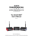
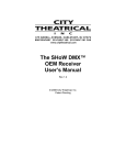
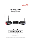
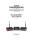
1
The PDS-375 TRX™ Power/Data Supply User’s Manual Rev 6 © 2010 City Theatrical, Inc. SHoW DMX® Transceivers are covered by U.S. Patent # 7,432,803 and other patents pending. Contents Figures ......................................................................................................................................... 3 Tables........................................................................................................................................... 3 Safety Notices ............................................................................................................................. 3 Introduction ................................................................................................................................. 5 PDS-375 TRX Features and Connections ................................................................................. 6 Front View .............................................................................................................................. 6 Rear View ............................................................................................................................... 7 Top View, Connections .......................................................................................................... 8 Left Side View ........................................................................................................................ 8 Right Side View, Mains Power ............................................................................................... 9 Color Kinetics CKDMX Output Pinout .................................................................................... 9 Installation and Setup ............................................................................................................... 10 Proper installation for convection cooling ............................................................................. 10 Mounting the PDS-375 TRX with hanging hardware ............................................................ 10 OPERATING THE PDS-375 TRX ............................................................................................... 10 User Interface ....................................................................................................................... 10 Configuring the PDS-375 TRX ............................................................................................. 11 Power................................................................................................................................... 11 CKDMX Ports ...................................................................................................................... 11 DMX512 Connections .......................................................................................................... 11 Ethernet Connections .......................................................................................................... 11 SHoW DMX Operation ......................................................................................................... 11 USB A Port .......................................................................................................................... 11 The Menus ........................................................................................................................... 12 PDS-375 TRX Æ (main menu) ........................................................................................... 12 The Setup Wizard ................................................................................................................ 12 Input Setup .......................................................................................................................... 12 Port Setup ............................................................................................................................ 14 Start Addressing .............................................................................................................. 14 Source Selection ............................................................................................................. 14 Personality ...................................................................................................................... 14 miniZapi ........................................................................................................................... 15 Scene Setup ........................................................................................................................ 15 RDM Setup .......................................................................................................................... 16 Misc. Setup .......................................................................................................................... 16 Stand-Alone Routines .......................................................................................................... 17 Fixed Color .......................................................................................................................... 17 Cross Fade .......................................................................................................................... 17 Color Wash .......................................................................................................................... 18 Color Wave 6 Light .............................................................................................................. 18 Color Wave 12 Light ............................................................................................................ 18 Color Wave 18 Light ............................................................................................................ 18 Random Color...................................................................................................................... 19 Random Fade ...................................................................................................................... 19 Appendix A: SHoW DMX Configuration Options .................................................................. 20 SHoW ID .............................................................................................................................. 20 Page 2 of 31 6550 PDS-375 TRX Manual R6.docxx SHoW DMX Neo Compatibility ............................................................................................ 20 Classic Mode Operation ...................................................................................................... 20 Neo Mode Operation ........................................................................................................... 22 Neo Adaptive Mode Operation ............................................................................................ 24 Power ................................................................................................................................... 25 RDM ..................................................................................................................................... 25 Appendix B: Compliance Information .................................................................................... 26 System Compliance Information........................................................................................... 26 Radio Compliance Information ............................................................................................. 26 Appendix C: Philips ColorBlast 12 TRX Control Flow Chart ................................................ 30 Appendix D: SHoW DMX Neo Compatibility .......................................................................... 31 Upgrade Paths ..................................................................................................................... 31 Firmware Only ..................................................................................................................... 31 Firmware Only Upgrade Verification: .......................................................................... 31 Firmware & Hardware .......................................................................................................... 31 Firmware & Hardware Upgrade Verification: .............................................................. 31 Figures Figure 1, PDS-375 TRX, Front View ............................................................................................. 6 Figure 2, PDS-375 TRX Rear View .............................................................................................. 7 Figure 3, PDS-375 TRX Top View ................................................................................................ 7 Figure 4, Left Side View ................................................................................................................ 8 Figure 5, Right Side View ............................................................................................................. 9 Figure 6, PDS-375 TRX User Interface ...................................................................................... 10 Tables Table 1: Classic SHoW ID Tables ............................................................................................... 20 Table 2: Neo SHoW ID Tables .................................................................................................... 22 Table 3: Neo Adaptive SHoW ID Table ...................................................................................... 24 Safety Notices Please read this entire manual before using your new equipment. Please keep the manual in a safe place so you can refer to it in the future as required. The CTI PDS-375 TRX is intended for use only by qualified professionals. Connection, installation and hanging of this equipment must be performed in accordance with all pertinent local, regional and national safety codes and regulations. The CTI PDS-375 TRX is intended for indoor use only. Keep the equipment dry. Do not operate the equipment if it gets wet. Do not operate in excessive heat/direct sunlight. Be sure installation provides adequate ventilation. Some system components can produce significant heat and must be properly installed to allow proper cooling and assure user safety. All sides of the equipment must be clear of obstruction and allow free airflow. Page 3 of 31 6550 PDS-375 TRX Manual R6.docxx The socket-outlet shall be installed near the equipment and shall be easily accessible. Output power of 24 V DC: 14 A max Maximum operating temperature: +0 °C to +40 °C With convection cooling: Maximum current at 32 °C (operating temperature of PDS-375 TRX) = 100 % = 14 Ampere load Maximum current at 40 °C (operating temperature of PDS-375 TRX) = 60 % of 14 A = 8.4 Ampere load There are no user-serviceable parts inside. Refer to qualified service personnel. Aucune maintenance ne doit être effectuée pour les pièces situées dans l’appareil. Les réparations et la maintenance doivent être executes uniquement par une personne qualifiée. RF Exposure: The antenna(s) used for this transmitter must be installed to provide a separation distance of at least 20cm from all persons and must not be collocated or operating in conjunction with any other antenna or transmitter. Page 4 of 31 6550 PDS-375 TRX Manual R6.docxx Introduction Thank you for selecting City Theatrical’s PDS-375 TRX. Every effort has been made to anticipate your questions in this manual, but if you have any questions that are not answered here, or you want to discuss a special application, please feel free to contact us directly at City Theatrical. The PDS-375 TRX is a Power/Data Supply (PDS) for CKDMX fixtures; it can be used with a controller or in stand-alone mode to power and control up to six 50W CKDMX fixtures, and offers control, configuration, and feedback options that have never been available before in a single unit. • Universal fixture support and flexible patching: You can use 2 color (iW Blast 12 TR), 3 color (ColorBlast 12 TR), and 5 color (ColorBlast 12 TRX) fixtures, you can use them in either 8 bit or 16 bit versions, and you can use them in any combination you choose. You can configure each of the 12 output ports differently, and you can address each port to a unique starting DMX address, or assign all the ports to a common starting DMX address. Use the PDS-375 TRX with any combination of 2, 3, or 5 color fixtures in either 8 or 16 bit mode and patch them without any wasted DMX slots. • Accepts all Industry Standard Control Protocols: You can control your PDS-375 TRX system (PDS and fixtures) with conventional wired DMX and RDM, Wireless DMX and RDM using the built-in SHoW DMX® receiver, Streaming ACN, Art-Net, or Ki Net, or with the built in MasterBlast™ Stand Alone routines. Whatever control data you use is output from the unit’s DMX512 output • Built-In 3 Port Managed Ethernet Switch: When using one of the Ethernet control protocols, you can assign the PDS-375 TRX system (PDS and fixtures) to one or two of the virtual DMX512 universes and assign a different virtual DMX512 universe to the DMX output. • Built-In SHoW DMX Receiver: When controlling the PDS-375 TRX with SHoW DMX wireless DMX, the DMX data is output from the unit’s DMX DMX512 Output. See Appendix D: SHoW DMX Neo Compatibility for SHoW DMX Neo compatibility. • Powerful new miniZapi features: You can use the enhanced built-in miniZapi to configure each of the connected CKDMX fixtures. • Quiet Convection Cooling: When operated in the normal upright position the PDS-375 TRX does not need a fan for cooling, it is convection cooled. • Universal Compliance: Each PDS-375 TRX is ETL and cETL Listed, CE certified and FCC part 15B compliant. Page 5 of 31 6550 PDS-375 TRX Manual R6.docxx PDS-375 TRX Features and Connections ` Figure 1, PDS-375 TRX, Front View Front View On the front of the PDS-375 TRX you will find the User Interface. The User Interface incorporates 5 pushbuttons and a 2x16 Character LCD Screen. Page 6 of 31 6550 PDS-375 TRX Manual R6.docxx Figure 2, PDS-375 TRX Rear View Rear View The power supply area is on the back of the unit and is covered by the Ventilation Grille. The Grille is an active part of the cooling system and must not be obstructed. Figure 3, PDS-375 TRX Top View Page 7 of 31 6550 PDS-375 TRX Manual R6.docxx Top View, Connections All of the input and output connections are located on the top of the PDS-375 TRX, including: • DMX-512 Input, 5PXLRM • DMX-512 Output, 5PXLRF • USB A Port (for firmware changes and upgrades) • 2 Ethernet Ports, RJ 45 compatible EtherCON • 6 CKDMX Ports, 4PXLRF In addition, the SHoW DMX antenna connection with the included (removable) 5 dBi omnidirectional antenna is also located on the top of the unit. Figure 4, Left Side View Left Side View The left side contains a ½” hole for use with a safety cable Page 8 of 31 6550 PDS-375 TRX Manual R6.docxx Figure 5, Right Side View Right Side View, Mains Power The PDS-375 TRX is provided with a universal input power supply and will operate on any mains power source 100-240 VAC 50/60 Hz. Each PDS-375 TRX is provided with a powerCON to NEMA 5-15P power cable. For use outside of North America, the NEMA 5-15P can be removed and replaced with the correct local connector. The power cord wire insulation color code is Mains Hot Mains Neutral Safety Earth Ground Brown Blue Green/Yellow Color Kinetics CKDMX Output Pinout The PDS-375 TRX CKDMX XLR 4P Output pinout is as follows: PIN # Pin 1 Pin 2 Pin 3 Pin 4 Signal +24VDC (n/c) Data DC Common CK Cable Wire Color Red White Black This pinout matches all Philips Color Kinetics ColorBlast 12 TRX, ColorBlast 12 TR, and iW Blast 12 TR fixtures and all other CTI PDS units, and is the industry standard. Page 9 of 31 6550 PDS-375 TRX Manual R6.docxx Installation and Setup Proper installation for convection cooling The PDS-375 TRX is designed to be convection cooled, so during normal operation the unit is cooled by airflow that occurs naturally due to convection through the Power Supply area. The unit should be operated in its normal upright position (handle up, feet down) with free and unrestricted airflow on all sides to assure proper convection cooling. The unit may either be placed on a flat surface on its feet or hung from appropriate user-provided hardware by its handle (see below) in the upright position. Note that the feet are part of the ventilation system and must be installed and in good condition if the unit is operated while standing on a flat surface. The PDS-375 TRX is provided with a supplemental fan (located on the bottom of the unit) which will turn on automatically if the unit is operated in a position other than the normal upright position. Do not obstruct the fan or block airflow to the fan. Mounting the PDS-375 TRX with hanging hardware The PDS-375 TRX may be hung with suitable hanging hardware using the two ½” holes provided in the Handle. Do not hang the unit from a single hanging device using only one of the two ½” holes, as excessive torque will be placed on the handle. A safety cable hole is provided in the Right Side of the unit for use with a user-provided safety cable when the unit is installed with hanging hardware. OPERATING THE PDS-375 TRX Figure 6, PDS-375 TRX User Interface User Interface The PDS-375 TRX is provided with a button pad for user control and an LCD screen that displays menu settings, configuration options, performance data, and any other text or graphics that relate to unit function. Press the Enter (center) button to access the menus, and press the Up or Down buttons to move through the menus. When you reach a menu that you want to work in, simply press Enter Page 10 of 31 6550 PDS-375 TRX Manual R6.docxx to begin editing. Press Enter again to save your changes. To cancel an edit, press and hold the Left button. Configuring the PDS-375 TRX Before you can use the PDS-375 TRX, you will need to configure it by selecting the input options and output options you wish to use. You can perform a basic configuration quickly using the Setup Wizard, or fine tune any input or output configuration settings by going directly to the menu for that option. Making Input and Output Connections Power The unit will work with 100-240VAC 50-60Hz mains power sources, and is provided with a powerCON to NEMA 5-15P plug for connection to US household style outlets. For use with other types of outlets, replace the plug with a suitable connector. CKDMX Ports Connect CKDMX fixtures in any desired arrangement; you can connect all of one type of fixture, or mix fixtures in any combination. If you combine different types of CKDMX fixtures, you will be able to configure each output port to match the fixture using the Port Setup Menu described below. DMX512 Connections Connect a standard 5P XLR DMX Cable to the 5P XLRM DMX input. The 5P XLRF Output will function as a standard hard-wired DMX pass-thru and is auto-terminated when no pass-thru cable is connected. Ethernet Connections Connect the Ethernet source to either etherCON RJ45 Compatible Ethernet port connector. The other EtherCON will function as a pass-thru port as long as the PDS-375 TRX is operating in Ethernet Input mode. If power to the unit is lost this Ethernet pass-thru will not function. SHoW DMX Operation Confirm the Antenna is installed and extended. Configure the SHoW ID to match the SHoW ID setting of the SHoW DMX Transmitter (sold separately) being used. See Appendix A: SHoW DMX Configuration Options page 20, and the SHoW DMX Users Manual for details. For SHoW DMX Neo Compatibility see Appendix D: SHoW DMX Neo Compatibility. USB A Port This port is used for firmware installation and upgrades only. Firmware updates are posted on the City Theatrical, Inc. website www.citytheatrical.com To install a firmware update: • Download the new firmware file from the CTI Website • Place file in root directory of a FAT (16 or 32) formatted USB memory stick. • Plug stick into USB jack • Browse to “Misc->Firmware->Update” • Wait for unit to reboot with new firmware • Once complete, remove USB stick Page 11 of 31 6550 PDS-375 TRX Manual R6.docxx Some USB memory devices do not meet the USB Standard, and may not work reliably with the PDS-375 TRX. If you have a problem, please contact City Theatrical for help. The Menus The PDS-375 TRX will power up in the configuration it was last set to. On power up, the unit will be in the Main Menu and the display will show: PDS-375 TRX Æ (main menu) [status] (status messages will vary with the input control method selected) (Æ) indicates that there is more information available by pressing the Right button. The Setup Wizard The Setup Wizard will guide you to configure basic setups for Wired DMX control, Wireless DMX control, or Ethernet control. To use the Setup Wizard, navigate to the Setup Wizard menu and press ENTER to Start. Continue to press ENTER to select choices and to move through the Wizard. Input Setup> Sets the input and control protocol to be used. Select DMX512-A, Art-Net, Streaming ACN, SHoW DMX or Internal Scenes. Personality> Sets a fixture personality for all 12 of the CKDMX ports. Select RGB3 16bit, RGB3 8-bit, iW 8-bit, RGBAW 16-bit, RGBAW 8-bit RGB5 16-bit, or RGB5 8-bit. Note, fixtures are automatically zapi-ed when PERSONALITY is selected to assure correct configuration Base Address> Sets the unit’s base DMX address and addresses the CKDMX ports sequentially. Select any DMX address from 1 -512 • Universe (when Ethernet is selected) • SHoW ID (When SHoW DMX is selected) Sets the SHoW ID (hopping pattern and bandwidth setting) for use in a SHoW DMX wireless DMX system. For more advanced and detailed configuration, proceed to the menu for the feature you wish to configure. Input Setup Use this menu to configure the PDS-375 TRX to accept control data from any one of the many supported control protocol options, and to set the various configuration options for each of the different protocols supported. This is a dynamic menu range; the options vary with the protocol selected, so options are only presented when they are pertinent to the selected protocol. When using one of the Ethernet protocols, the PDS-375 TRX’s outputs can be assigned to any supported Universe while the DMX output is assigned to a different supported Universe. Control Method • E1.11 DMX-512 (selects DMX) • Internal Scenes (selects Internal Scenes) • ArtNet (selects Art-Net and enables the Art-Net configuration options below) Page 12 of 31 6550 PDS-375 TRX Manual R6.docxx Universe 0-0 thru f-f (select from 256 Universes as 16 subnets, each with 16 Universes) o Network Settings (configure Art-Net network settings) IP Address Mode • Manual • Auto IP Address Subnet Address Gateway Address MAC Address o Universe Format Hexadecimal (displays Universes according to standard Art-Net convention) PRG Alpha (displays universes according to PRG’s Alpha-numeric convention Decimal (displays Universes with decimal labels 1-256) o PRG Merge (by default, multiple sources for the same Universe are HTP merged) Auto (Art-Net Default) LTP 1 Way 2 Way 3 Way 4 Way o • E1.31 sACN (selects streaming DMX over ACN and enables the sACN configuration options below) o Universe 1-63999 (select from 64,000 Universes) o Network Settings (configure sACN network settings) IP Address Mode • Manual • Auto IP Address Subnet Address Gateway Address MAC Address (by default, multiple sources for the same Universe are HTP merged, max number of sources is two) • SHoW DMX (selects SHoW DMX wireless DMX and enables the SHoW DMX configuration options, see SHoW DMX Configuration Options, page 20 and Appendix D: SHoW DMX Neo Compatibility) o SHoW ID (select SHoW ID) 1-64, 101-164, 201-204 o SHoW Power (select SHoW DMX broadcast power for RDM responses) Classic: 5mW-100mW (ETSI) Page 13 of 31 6550 PDS-375 TRX Manual R6.docxx Neo: 1mW- 72mW (ETSI) Port Setup This menu is used to configure the CKDMX Ports for the various fixture types supported. Each CKDMX Port can be individually configured, or all 6 Ports can be set to the same configuration. Start Addressing (select a starting address for the whole unit with Base Address, or set individual starting addresses for each Port with Port 1 Address through Port 6 Address) • Base Address – 1-512 • Port 1 Address – 1-512 • Port 2 Address – 1-512 • Port 6 Address – 1-512 Source Selection (Select Universe in Ethernet control methods; select a source for the whole unit with All Sources, or set individual Sources for each Port with Port 1 Source through Port 6 Source) – All Sources – Port 1 Source – Port 2 Source, – Port 6 Source Personality (select a common fixture personality for the whole unit with All Personality, or set individual personalities for each Port with Port 1 Personality through Port 6 Personality) – All Personality – Port 1 Personality – Port 2 Personality – Port 6 Personality Fixture Personalities: PASS-THRU iW 8-bit RGBAW 16-bit RGBAW 8-bit RGB5 16-bit RGB5 8-bit RGB3 16-bit RGB3 8-bit Page 14 of 31 6550 PDS-375 TRX Manual R6.docxx miniZapi The min-zapi menu allows individual configuration of connected CKDMX fixtures, including resetting the fixture to the default CKDMX “Light 1” (starting DMX address 001) and selection of 8 or 16 bit operation. Connected fixtures may be zapi-ed together using All mZapi (all miniZapi) or may be zapi-ed individually using individual Port mZapi (Port miniZapi). The zapi configuration options for All mZapi and individual Port mZapi are the same and are listed below: • All mZapi or • Port 1-6 mZapi – Set Address to 1 – Set DMX Mode – Set LED D4 – D1 – Set LED Fast – Set Contrl RGB5 – Set Contrl RGB3 – Set Contrl RGBAW – Set Tung. Curve – Set Normal Curve – Set Linear Curve – Set 8 bit mode – Set 16 bit mode Scene Setup In the Scene Setup menu you can assign any one of the stand-alone routines to each of 6 Scenes and then configure the unit to play those Scenes in the order and times you select using the Fade Time and Follow Time settings. Fade Time sets the fade time within the routine assigned to the Scene, e.g. the time for a cross fade between colors in Color Wash. Follow Time sets the time the Scene will play before the unit moves to the next assigned Scene. An internal Grand Master setting is also applied when running the PDS-375 TRX in this mode. Up to 6 Scenes can be configured and any unused Scenes can be disabled. Use the > Menu settings to set the Grandmaster level, fade time and follow time for each Scene. Select Internal Scenes in the Input Menu to edit Scenes live and enable playback. Scene1: > • Disabled • Fixed Color • Random Fade • Random Color • Colorwave 18Lgt • Colorwave 12Lgt • Colorwave 16Lgt • Cross Fade • Color Wash Page 15 of 31 6550 PDS-375 TRX Manual R6.docxx > menu settings: Grandmaster: • 000 – 100% Fade Time: • .2 Sec. – 2 Hours Follow Time: • .1 Sec – 2 Hours or 0 (infinite) Color 1/Fixed: • R:00-FF G:00-FF B:00-FF A:00-FF W:00-FF (editing either Fixed or Color 1 sets RGB levels for both routines) Color 2: • R:00-FF G:00-FF B:00-FF Scene 2: Scene 3: Scene 4: Scene 5: Scene 6: > (as above) > (as above) > (as above) > (as above) > (as above) RDM Setup Proxy Enable • Enabled • Disabled Device Label: >< • [user entered 32 characters] Unique ID: [factory set] Misc. Setup Panel Lockout: • 5-240 seconds • Disabled To clear Panel Lockout, press and hold the Right and Left Buttons at the same time Backlight T-out: • Always on • Always off • 1-240 Seconds Firmware [firmware version] Restore Default? Page 16 of 31 6550 PDS-375 TRX Manual R6.docxx • Are you sure? [working] Data Hold T-Out: • 0-Infinite CK Quiet Mode: • On • Off When CK Quiet Mode is ON, the CKDMX outputs are turned off unless level changes occur, so static DMX levels are not constantly refreshed. This feature is provided for use in installations where data traffic on the fixture cables must be minimized. Stand-Alone Routines The PDS-375 TRX contains eight stand-alone routines, which can be assigned to the six preset Scenes. 1 In the stand-alone routines, the PDS-375 TRX outputs the selected routine as a DMX signal from its 5PXLR wired DMX output port. You may setup Internal Scenes from the Setup Wizard or follow the following procedure to set up Internal Scenes directly using the Scene Setup Menu: To select Stand-Alone Routines (Not using Setup Wizard): From the Top Menu, push the Enter Button to access the various Setup Menu choices, use the Down Button to scroll to Advanced Setup and select (Enter Button) Under Control Method: select Internal Scenes Use up/down arrows to navigate to Port Setup and select (Enter Button) use the Down Button to scroll to Personality and select (Enter Button) Under All Personality: select RGBAW 8-bit Back up to the Setup Menu and scroll to Scene Setup to assign Stand-Alone Routines to Scenes (1-6) and configure the Routines selected. Set unused Scenes to Disabled. Make sure your LED fixtures are either RGB only fixtures (TR series) or set for RGBAW 8-bit (TRX series). Fixed Color This show routine holds a single user selectable color. The Color setting is displayed as Red, Green, Blue, Amber and White (RGBAW) levels in hexadecimal. Press the Enter button to edit the colors. A blinking cursor will appear under the first character in the R level. Use the Up and Down button to adjust. Use the Left and Right buttons to move to the other character fields. You can monitor the level by watching a connected ColorBlast as the output is updated while you adjust these levels. When you have completed setting the color push Enter to record your setting. Cross Fade This show routine executes a continuous cross fade between two RGB colors. The adjustable parameters are the fade rate and color selection. To adjust the fade rate, go to the Color Fade 1 These Stand-Alone routines match the built-in Routines provided in the CTI MasterBlast Controller. Page 17 of 31 6550 PDS-375 TRX Manual R6.docxx routine and press Enter. A blinking cursor will appear under the fade time. Adjust the fade time by pressing the Up and Down buttons. Fade time is adjustable between .25 Seconds and 2 hours. To select the Colors for the cross fade, go to the Color Fade routine and press the Right button. The display will change to show the current Color 1 or Color 2 setting. The Color setting is displayed as Red Green and Blue (RGB) levels in hexadecimal. Press the Enter button to edit the colors. A blinking cursor will appear under the first character in the R level. Use the Up and Down button to adjust. Use the Left and Right buttons to move to the other character fields. You can monitor the level by watching a connected ColorBlast, as the output is updated while you adjust these levels. When you have completed setting one color push Enter to record your setting and use the Up and Down buttons to go to the other color. PDS-375 TRX will continually broadcast this 3 color routine via its DMX512 Output configured as RGBAW 8-bit personality. Color Wash This show routine executes a continuous cross fade between colors. The adjustable parameter is the fade rate. To adjust the fade rate, go to the Color Wash routine and press Enter. A blinking cursor will appear under the fade time. Adjust the fade time by pressing the Up and Down buttons. Fade time is adjustable between .2 Seconds and 2 hours. PDS-375 TRX will continually broadcast this 3 color routine via its DMX512 Output configured as RGBAW 8-bit personality. Color Wave 6 Light This show routine executes as a sequential color spectrum cross fade between six lights, where the six lights are sequentially addressed (DMX1,2,3; 4,5,6; 7,8,9; etc.). The effect is of a color spectrum or rainbow moving around the sequentially addressed fixtures. The adjustable parameter is the fade rate. To adjust the fade rate, go to the Color Wave 6 Lgt routine and press Enter. A blinking cursor will appear under the fade time. Adjust the fade time by pressing the Up and Down buttons. Fade time is adjustable between .2 Seconds and 2 hours. PDS-375 TRX will continually broadcast this 3 color routine via its DMX512 Output configured as RGBAW 8-bit personality. Color Wave 12 Light This show routine executes as a sequential color spectrum cross fade between 12 lights, where the 12 lights are sequentially addressed (DMX1,2,3; 4,5,6; 7,8,9; etc.). The effect is the same as Color Wave 6 Light except the Color Wave effect is smoother as it moves across more fixtures. The adjustable parameter is the fade rate. To adjust the fade rate, go to the Color Wave 12 Lgt routine and press Enter. A blinking cursor will appear under the fade time. Adjust the fade time by pressing the Up and Down buttons. Fade time is adjustable between .2 Seconds and 2 hours. PDS-375 TRX will continually broadcast this 3 color routine via its DMX512 Output configured as RGBAW 8-bit personality. Color Wave 18 Light This show routine executes as a sequential color spectrum cross fade between 18 lights, where the 18 lights are sequentially addressed (DMX1,2,3; 4,5,6; 7,8,9; etc.). The effect is the same as Color Wave 6 Light and 12 Light except the Color Wave effect is even smoother than in the 6 or 12 Light versions. The adjustable parameter is the fade rate. To adjust the fade rate, go to the Color Wave 18 Lgt routine and press Enter. A blinking cursor will appear under the fade time. Adjust the fade time by pressing the Up and Down buttons. Fade time is adjustable between .2 Seconds and 2 hours. PDS-375 TRX will continually broadcast this 3 color routine via its DMX512 Output configured as RGBAW 8-bit personality. Page 18 of 31 6550 PDS-375 TRX Manual R6.docxx Random Color This show routine executes changes (‘bumps”) between randomly selected colors. The adjustable parameter is the change rate. To adjust the change rate, go to the Random Color routine and press Enter. A blinking cursor will appear under the change time. Adjust the time by pressing the Up and Down buttons. Change time is adjustable between .2 Seconds and 2 hours. PDS-375 TRX will continually broadcast this 3 color routine via its DMX512 Output configured as RGBAW 8-bit personality. Random Fade This show routine is similar to the color wash routine except that color selection is random. The adjustable parameter is the fade rate. To adjust the fade rate, go to the Random Color routine and press Enter. A blinking cursor will appear under the fade time. Adjust the fade time by pressing the Up and Down buttons. Fade time is adjustable between .2 Seconds and 2 hours. PDS-375 TRX will continually broadcast this 3 color routine via its DMX512 Output configured as RGBAW 8-bit personality. When playing Scenes from the Top Menu, press Up/Down to change scenes. If a follow time for a Scene is set to other than 0 sec., the Scene will automatically change to the next Scene at the end of the follow time. If the current Scene is # 6, the next Scene will be # 1. Page 19 of 31 6550 PDS-375 TRX Manual R6.docxx Appendix A: SHoW DMX Configuration Options SHoW ID The SHoW ID Setting configures the SHoW DMX Radio parameters, including hopping pattern selection and full or limited bandwidth broadcast modes. All SHoW DMX equipment in a given system must share the same SHoW ID in order to communicate. SHoW ID 201 is the default setting for all SHoW DMX equipment. There are 3 types of modes that the device can function in: Classic, Neo, and Neo Adaptive. SHoW DMX Neo Compatibility Please see Appendix D: SHoW DMX Neo Compatibilityfor more information on compatibility of SHoW DMX Neo SHoW IDs (IDs > 64) with older power supplies. Classic Mode Operation In Classic Mode, the SHoW DMX Neo system operates identically to a Classic 5600 series SHoW DMX system and will communicate with 5600 units. You can use this mode if you want to combine SHoW DMX Neo and Classic equipment in the same system. Classic Mode supports Adjustable Broadcast Power, Limited Bandwidth, Limited Burst, and uses 64 original SHoW IDs, providing 16 hopping patterns in each Bandwidth setting. Table 1: Classic SHoW ID Tables SHoW ID Mode Hopping Pattern Bandwidth 1 Classic 1 Full 2 Classic 2 Full 3 Classic 3 Full 4 Classic 4 Full 5 Classic 5 Full 6 Classic 6 Full 7 Classic 7 Full 8 Classic 8 Full 9 Classic 9 Full 10 Classic 10 Full 11 Classic 11 Full 12 Classic 12 Full 13 Classic 13 Full 14 Classic 14 Full 15 Classic 15 Full 16 Classic 6550 PDS-375 TRX Manual R6.docxx 16 Page 20 of 31 Full SHoW ID Mode Hopping Pattern Bandwidth 17 Classic 1 Limited Low, Wi Fi 1-6 18 Classic 2 Limited Low, Wi Fi 1-6 19 Classic 3 Limited Low, Wi Fi 1-6 20 Classic 4 Limited Low, Wi Fi 1-6 21 Classic 5 Limited Low, Wi Fi 1-6 22 Classic 6 Limited Low, Wi Fi 1-6 23 Classic 7 Limited Low, Wi Fi 1-6 24 Classic 8 Limited Low, Wi Fi 1-6 25 Classic 9 Limited Low, Wi Fi 1-6 26 Classic 10 Limited Low, Wi Fi 1-6 27 Classic 11 Limited Low, Wi Fi 1-6 28 Classic 12 Limited Low, Wi Fi 1-6 29 Classic 13 Limited Low, Wi Fi 1-6 30 Classic 14 Limited Low, Wi Fi 1-6 31 Classic 15 Limited Low, Wi Fi 1-6 32 Classic 16 Limited Low, Wi Fi 1-6 SHoW ID Mode Hopping Pattern Bandwidth 33 Classic 1 Limited Mid, Wi Fi 5-9 34 Classic 2 Limited Mid, Wi Fi 5-9 35 Classic 3 Limited Mid, Wi Fi 5-9 36 Classic 4 Limited Mid, Wi Fi 5-9 37 Classic 5 Limited Mid, Wi Fi 5-9 38 Classic 6 Limited Mid, Wi Fi 5-9 39 Classic 7 Limited Mid, Wi Fi 5-9 40 Classic 8 Limited Mid, Wi Fi 5-9 41 Classic 9 Limited Mid, Wi Fi 5-9 42 Classic 10 Limited Mid, Wi Fi 5-9 43 Classic 11 Limited Mid, Wi Fi 5-9 44 Classic 12 Limited Mid, Wi Fi 5-9 45 Classic 13 Limited Mid, Wi Fi 5-9 46 Classic 14 Limited Mid, Wi Fi 5-9 Page 21 of 31 6550 PDS-375 TRX Manual R6.docxx 47 Classic 15 Limited Mid, Wi Fi 5-9 48 Classic 16 Limited Mid, Wi Fi 5-9 SHoW ID 49 50 51 52 Mode Classic Classic Classic Hopping Pattern 1 2 3 Bandwidth Limited High, Wi Fi 7-11 Limited High, Wi Fi 7-11 Limited High, Wi Fi 7-11 Classic 4 Limited High, Wi Fi 7-11 53 Classic 5 Limited High, Wi Fi 7-11 54 Classic 6 Limited High, Wi Fi 7-11 55 Classic 7 Limited High, Wi Fi 7-11 56 Classic 8 Limited High, Wi Fi 7-11 57 Classic 9 Limited High, Wi Fi 7-11 58 Classic 10 Limited High, Wi Fi 7-11 59 Classic 11 Limited High, Wi Fi 7-11 60 Classic 12 Limited High, Wi Fi 7-11 61 Classic 13 Limited High, Wi Fi 7-11 62 Classic 14 Limited High, Wi Fi 7-11 63 Classic 15 Limited High, Wi Fi 7-11 64 Classic 16 Limited High, Wi Fi 7-11 Neo Mode Operation In Neo Mode, the SHoW DMX Neo system uses a new broadcast format that reduces latency to ~ 7mS max and provides further resistance to interference susceptibility or creation. Neo Mode supports Adjustable Broadcast Power, Limited Bandwidth, Limited Burst, and uses 64 new SHoW IDs, providing 16 hopping patterns in each Bandwidth setting. Table 2: Neo SHoW ID Tables SHoW ID Mode 101 102 103 104 105 106 107 108 109 Neo Neo Neo Neo Neo Neo Neo Neo Neo Hopping Pattern 1 2 3 4 5 6 7 8 9 Page 22 of 31 6550 PDS-375 TRX Manual R6.docxx Bandwidth Full Full Full Full Full Full Full Full Full 110 111 112 113 114 115 116 Neo Neo Neo Neo Neo Neo Neo 10 11 12 13 14 15 16 Full Full Full Full Full Full Full SHoW ID 117 118 119 120 121 122 123 124 125 126 127 128 129 130 131 132 Mode Neo Neo Neo Neo Neo Neo Neo Neo Neo Neo Neo Neo Neo Neo Neo Neo Hopping Pattern 1 2 3 4 5 6 7 8 9 10 11 12 13 14 15 16 Bandwidth Limited Low, Wi-Fi 1-6 Limited Low, Wi-Fi 1-6 Limited Low, Wi-Fi 1-6 Limited Low, Wi-Fi 1-6 Limited Low, Wi-Fi 1-6 Limited Low, Wi-Fi 1-6 Limited Low, Wi-Fi 1-6 Limited Low, Wi-Fi 1-6 Limited Low, Wi-Fi 1-6 Limited Low, Wi-Fi 1-6 Limited Low, Wi-Fi 1-6 Limited Low, Wi-Fi 1-6 Limited Low, Wi-Fi 1-6 Limited Low, Wi-Fi 1-6 Limited Low, Wi-Fi 1-6 Limited Low, Wi-Fi 1-6 SHoW ID 133 134 135 136 137 138 139 140 141 142 143 Mode Neo Neo Neo Neo Neo Neo Neo Neo Neo Neo Neo Hopping Pattern 1 2 3 4 5 6 7 8 9 10 11 Page 23 of 31 Bandwidth Limited Mid, Wi-Fi 5-9 Limited Mid, Wi-Fi 5-9 Limited Mid, Wi-Fi 5-9 Limited Mid, Wi-Fi 5-9 Limited Mid, Wi-Fi 5-9 Limited Mid, Wi-Fi 5-9 Limited Mid, Wi-Fi 5-9 Limited Mid, Wi-Fi 5-9 Limited Mid, Wi-Fi 5-9 Limited Mid, Wi-Fi 5-9 Limited Mid, Wi-Fi 5-9 6550 PDS-375 TRX Manual R6.docxx 144 145 146 147 148 SHoW ID 149 150 151 152 153 154 155 156 157 158 159 160 161 162 163 164 Neo Neo Neo Neo Neo Mode Neo Neo Neo Neo Neo Neo Neo Neo Neo Neo Neo Neo Neo Neo Neo Neo 12 13 14 15 16 Limited Mid, Wi-Fi 5-9 Limited Mid, Wi-Fi 5-9 Limited Mid, Wi-Fi 5-9 Limited Mid, Wi-Fi 5-9 Limited Mid, Wi-Fi 5-9 Hopping Pattern 1 2 3 4 5 6 7 8 9 10 11 12 13 14 15 16 Bandwidth Limited High, Wi-Fi 7-11 Limited High, Wi-Fi 7-11 Limited High, Wi-Fi 7-11 Limited High, Wi-Fi 7-11 Limited High, Wi-Fi 7-11 Limited High, Wi-Fi 7-11 Limited High, Wi-Fi 7-11 Limited High, Wi-Fi 7-11 Limited High, Wi-Fi 7-11 Limited High, Wi-Fi 7-11 Limited High, Wi-Fi 7-11 Limited High, Wi-Fi 7-11 Limited High, Wi-Fi 7-11 Limited High, Wi-Fi 7-11 Limited High, Wi-Fi 7-11 Limited High, Wi-Fi 7-11 Neo Adaptive Mode Operation The SHoW DMX Neo system can be configured to operate in the new Neo Adaptive (AFHSS) Mode. Neo Adaptive Mode uses an Adaptive Spread Spectrum Frequency Hopping broadcast format in which the system detects interference and adapts its frequency hopping channel set automatically to avoid it. Neo Adaptive Mode supports Adjustable Broadcast Power and uses 4 new Adaptive Mode SHoW IDs. Latency is also reduced to ~7mS max in Adaptive Mode. Table 3: Neo Adaptive SHoW ID Table SHoW ID 201 202 203 204 Mode Neo Adaptive Neo Adaptive Neo Adaptive Neo Adaptive Universe A B C D Page 24 of 31 6550 PDS-375 TRX Manual R6.docxx Bandwidth Full Full Full Full The SHoW DMX System supports 16 different Frequency Hopping Spread Spectrum (FHSS) hopping patterns, full bandwidth broadcasting mode, and three different limited bandwidth broadcasting modes. The SHoW IDs allow the user to quickly select the desired combination of Hopping Pattern and Full or Limited Broadcast option that is desired. Please see The Advanced Wireless DMX Broadcast Features of SHoW DMX in the SHoW DMX System User’s Manual 2 for more about how these features can be used. Power This menu allows adjustment of radio broadcast power which is used during wireless RDM responses. RDM Device Label: This label is user defined. You can edit the label by pushing the Enter button. A blinking cursor will appear under the first character in the label. Use the Up and Down Buttons to change characters and use the Right and Left buttons to move through the text string. Press Enter again to record your label. For example, if you had PDS-375 TRXs located in front of the DJ Booth, you could give them RDM Labels like “DJ Booth Left” and “DJ Booth Right” Unique ID: The RDM unique ID is factory set and unique for each RDM responder. PDS-375 TRX is a fully compliant RDM Receive Responder and can be monitored and configured via wireless RDM using the SHoW DMX RDM Monitor (embedded in the SHoW DMX Transmitter). The following device information is available via wireless RDM: • Unique RDM ID (read) • Device Label (set and read) • Starting DMX Address (set and read) • Output fault status (read) • Port configuration • SHoW ID (set and read) • Broadcast Power (set and read) • Receive signal strength (read) • Internal PCBA temperature (read) • Power supply voltage (read) For more details, see The SHoW DMX System User’s Manual. 2 Available as a free download from the CTI website at www.citytheatrical.com Page 25 of 31 6550 PDS-375 TRX Manual R6.docxx Appendix B: Compliance Information System Compliance Information The City Theatrical 6500 PDS-375 TRX is CE Certified Standards Applied: EN 55103-1, EN55103-2 EN 60950-1:2006 Product Conforms to CE Marking Directive 93/68/EEC The City Theatrical 6500 PDS-375 TRX is RoHS compliant The City Theatrical 6500 PDS-375 TRX is ETL and cETL Listed and conforms to UL STD 508A and is certified to CAN/CSA STD C22.2 NO. 14-95 About the SHoW DMX Radios installed: The City Theatrical 6500 PDS-375 TRX is equipped with a CE compliant City Theatrical 5792 SHoW DMX Radio which is FCC and IC Certified for use in the US and Canada and is CE Certified for use in Europe Radio Compliance Information 5792 SHoW DMX Neo™ Radio Module FCC ID: VU65792 IC ID: 7480A5792 FCC Part 15 This equipment has been tested and found to comply with the limits for a Class B digital device, pursuant to part 15 of the FCC Rules. These limits are designed to provide reasonable protection against harmful interference in a residential installation. This equipment generates, uses and can radiate radio frequency energy and, if not installed and used in accordance with the instructions, may cause harmful interference to radio communications. However, there is no guarantee that interference will not occur in a particular installation. If this equipment does cause harmful interference to radio or television reception, which can be determined by turning the equipment off and on, the user is encouraged to try to correct the interference by one or more of the following measures: • Reorient or relocate the receiving antenna. • Increase the separation between the equipment and receiver. • Connect the equipment into an outlet on a circuit different from that to which the receiver is connected. • Consult the dealer or an experienced radio/ TV technician for help. Radio Frequency Notifications FCC Notifications RF Radiation The Product is an intentional radiator of Radio Frequency (RF) energy. In order to limit RF exposure to personnel in the immediate area, the Product should be located and installed such that a separation of at least 20 centimeters is maintained between the Product’s antenna and personnel in the vicinity of the device. Modification Warning Caution: changes or modifications to this equipment, not expressly approved by City Theatrical Inc. could void the user’s authority to operate the equipment. Industry Canada Notifications Page 26 of 31 6550 PDS-375 TRX Manual R6.docxx This Class B digital apparatus complies with Canadian ICES-003. Operation is subject to the following two conditions: (1) this device may not cause interference, and (2) this device must accept any interference, including interference that may cause undesired operation of the device. Cet appareil numérique de la classe B est conforme à la norme NMB-003 du Canada. Product Installation and Configuration Guide © City Theatrical Inc. 2007 5792 Approved Antenna To reduce potential radio interference to other users, the antenna type and its gain should be so chosen that the equivalent isotropically radiated power (e.i.r.p.) is not more than that permitted for successful communication. This device has been designed to operate with the antennas listed below. Antennas not included in this list or having a gain greater than 5 dB are strictly prohibited for use with this device. The required antenna impedance is 50 ohms. 5792 FCC/IC Approved Antennas: Manufacturer Model Type Connector Gain Nearson S151AH-2450S Omni whip SMA plug reverse polarity 5dBi Nearson S141AH-2450 Omni whip SMA plug reverse polarity 2dBi Nearson S131AH-2450 Omni whip 2dBi Nearson DG102N-2.4/5.25 Omni whip Centurion WCP2400-MMCX4 Omni whip Maxrad MP24008XFPT Panel Maxrad MYP24010PT Yagi Maxrad MYP24014PT Yagi SMA plug reverse polarity SMA plug reverse polarity via provided Antenna Cable MMCX jack on 4” coax pigtail SMA plug reverse polarity via provided Antenna Cable SMA plug reverse polarity via provided Antenna Cable SMA plug reverse polarity via provided Antenna Cable 5dBi 2.5dBi 8dBi 10dBi 14dBi 5792 CE Approved Antennas: Manufacturer Model Type Connector Gain Nearson S151AH-2450S Omni whip SMA plug reverse polarity 5dBi Nearson S141AH-2450 Omni whip SMA plug reverse polarity 2dBi Nearson S131AH-2450 Omni whip 2dBi Nearson DG102N-2.4/5.25 Omni whip Centurion WCP2400-MMCX4 Omni whip SMA plug reverse polarity SMA plug reverse polarity via provided Antenna Cable MMCX jack on 4” coax pigtail 5dBi 2.5dBi CE Mark Conformity City Theatrical Inc. declares that this product conforms to the specifications listed in this manual, following the provisions of the European R&TTE directive 1999/5/EC: City Theatrical Inc. vakuuttaa täten että dieses produkt tyyppinen laite on direktiivin 1999/5/EY oleellisten vaatimusten ja sitä koskevien näiden direktiivien muiden ehtojen mukainen. City Theatrical Inc. déclare que le produit est conforme aux conditions essentielles et aux dispositions relatives à la directive 1999/5/EC. • EN 301 489-1, 301 489-17 General EMC requirements for Radio equipment. Page 27 of 31 6550 PDS-375 TRX Manual R6.docxx • EN 60950 Safety • EN 300 328 Technical requirements for Radio equipment. CAUTION—This equipment is intended to be used in all EU and EFTA countries. Outdoor use may be restricted to certain frequencies and/or may require a license for operation. Contact local Authority for procedure to follow. Note: ESD precautions should be used when attaching or removing the antenna. Note: Combinations of power levels and antennas resulting in a radiated power level of above 100 mW equivalent isotropic radiated power (EIRP) are considered as not compliant with the above mentioned directive and are not allowed for use within the European community and countries that have adopted the European R&TTE directive 1999/5/EC. For more details on legal combinations of power levels and antennas, contact City Theatrical Inc. Do not use this product near water, for example, in a wet basement or near a swimming pool. Avoid using this product during an electrical storm. There may be a remote risk of electric shock from lightning. Product Installation and Configuration Guide © City Theatrical Inc. 2011 Q52 Regulatory information Radio Frequency Notifications Belgique Dans le cas d'une utilisation privée, à l'extérieur d'un bâtiment, au-dessus d'un espace public, aucun enregistrement n'est nécessaire pour une distance de moins de 300m. Pour une distance supérieure à 300m un enregistrement auprès de l'IBPT est requise. Pour une utilisation publique à l'extérieur de bâtiments, une licence de l'IBPT est requise. Pour les enregistrements et licences, veuillez contacter l'IBPT. France 2.4 GHz Bande : les canaux 10, 11, 12, 13 (2457, 2462, 2467, et 2472 MHz respectivement) sont complétement libres d'utilisation en France (en utilisation intérieur). Pour ce qui est des autres canaux, ils peuvent être soumis à autorisation selon le départment. L'utilisation en extérieur est soumis à autorisation préalable et très restreint. Vous pouvez contacter l'Autorité de Régulation des Télécommunications (http://www.art-telecom.fr) pour de plus amples renseignements. Page 28 of 31 6550 PDS-375 TRX Manual R6.docxx 5792 SHoW DMX Neo Radio CE Declaration of Conformity Page 29 of 31 6550 PDS-375 TRX Manual R6.docxx Appendix C: Philips ColorBlast 12 TRX Control Flow Chart LOCK ADDR 1–512 Set the fixture’s starting DMX address DMX Menu Button Behavior MODE Put the fixture in DMX mode or fixed color mode Return Returns to the previous menu in the tree FIXD CFG RED 0–255 GRN 0–255 BLUE 0–255 AMBR 0–255 WHT 0–255 NORM Set the fixture’s color control mode Set the fixture’s resolution CTRL Enter Advances to the next menu, or confirms selection Up Moves up in the current menu’s set of options Down Moves down in the current menu’s set of options 5-channel (RGBAW) DMX input, 5-channel output RGB5 3-channel (RGB) DMX input mapped to 5-channel output RGB3 3-channel (RGB) DMX input, 3-channel output (no A or W) 8 8-bit 16 16-bit BIT NORM Set the fixture’s dimming curve Set the fixed color to display in standalone mode by adjusting the intensity of each channel CURV LINR TUNG FAST Gamma curve that matches most Philips Color Kinetics fixtures Linear relationship between DMX input and power output Tungsten / incandescent dimming curve Fastest setting: Instant snap when intensity changes D–1 Set the LED transition speed SPD D–2 D–3 D–4 TEST RUN Slowest setting Run the fixture self-test UTIL Display information about the fixture INFO MAIN Firmware version of main LED board VER UI S/N Set the menu unlock time UNLK Save current settings as profiles, and load saved profiles Firmware version of menus (user interface) Serial number TEMP Current internal operating temperature VOLT Current input voltage 1 1 second 2 2 seconds 5 5 seconds PROF Reapply initial factory settings DFLT Yes LOAD 1 Reapply saved profile 1 2 Reapply saved profile 2 1 Save current settings as profile 1 2 Save current settings as profile 2 SAVE Page 30 of 31 6550 PDS-375 TRX Manual R6.docxx No RESTORE DEFAULTS? Appendix D: SHoW DMX Neo Compatibility Power supplies shipped before June 1st 2012 are not compatible with SHoW DMX Neo SHoW IDs (IDs 101 - 204) without an upgrade. Firmware version 1.4.0 or higher and SHoW DMX Neo radio hardware are required for SHoW DMX Neo compatibility. Firmware version 1.4.0 or higher is compatible with all power supplies. If 1.4.0 or higher is installed with a SHoW DMX Classic radio, you will get the latest in bug fixes, but will not be able to set any SHoW DMX Neo IDs. There are two upgrade paths, firmware only and firmware with hardware via Cat # 6599 PDS TRX Neo Upgrade Kit. The path required depends on the SHoW DMX radio hardware installed in your power supply. Upgrade Paths Firmware Only For power supplies shipped between October 1st 2011 and May 31st 2012, the power supply only requires updated firmware, available from our web site (www.citytheatrical.com). If your power supply has any of the below characteristics, you can upgrade using the firmware only path. Firmware Only Upgrade Verification: • Model number on bottom of unit is 6500 Neo • SHoW DMX Neo equipped sticker on face of power supply • Menu item Misc->Firmware->Radio Type is “Neo (CE)” (Available in firmware version 1.3.4 and above) Firmware & Hardware For power supplies shipped before October 1st 2011, both firmware and radio hardware are require to be compatible with SHoW DMX Neo systems. City Theatrical has created an upgrade kit for purchase as Cat # 6599 PDS TRX Neo Upgrade Kit. This kit can be purchased through your dealer. Please check with your dealer for pricing. This kit includes the SHoW DMX Neo radio and a USB drive with the latest firmware along with new labels for your power supply. If you prefer to not install the kit yourself, you can call City Theatrical for a RMA and send the power supply back to City Theatrical for installation at an additional charge. If your power supply has any of the below characteristics, you need Cat # 6599 PDS TRX Neo Upgrade Kit. Firmware & Hardware Upgrade Verification: • Model number on bottom of unit is 6500 • Firmware version is 1.3.3 or lower • Menu item Misc->Firmware->Radio Type is “Classic (CE)” (Available in firmware version 1.3.4 and above) • Menu item Misc->Firmware->Radio Type is “Classic (NA)” (Available in firmware version 1.3.4 and above) Page 31 of 31 6550 PDS-375 TRX Manual R6.docxx