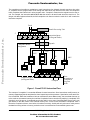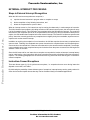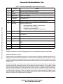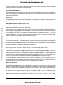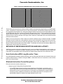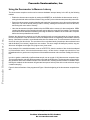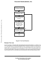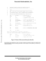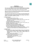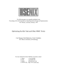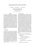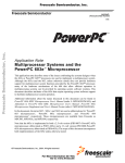
1
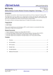
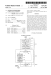
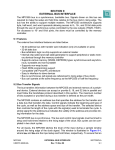
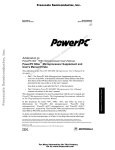
Freescale Semiconductor
Order this document by
AN1267/D
AN1267
Application Note
PowerPC 603™ Hardware Interrupt Latency In
Embedded Applications
Freescale Semiconductor, Inc...
By Wendell Smith, Paul Nelson, and Amy Dyson, High Performance Embedded Systems
The PowerPC™ 603 microprocessor is a RISC design, achieving a high level of performance using instruction
pipelining and a superscalar architecture. In addition to branch folding, two instructions may complete in a single
cycle and as many as five instructions may execute simultaneously. This parallelism complicates how quickly
the processor can service external interrupts. For example, when an external device requests an interrupt, a
store may be pending; to maintain program coherency, that store must complete before the 603 branches to
the interrupt handler.
The PowerPC 603 microprocessor completes one instruction before recognizing an external interrupt. That one
instruction may cause exceptions such as an illegal operation exception, delaying the handling of the external
interrupt. We demonstrate that few of these instruction-caused exceptions occur in an embedded application
as compared to a general desktop computing environment.
In this paper, we examine the instruction flow, the interrupt recognition method, and interrupt latency factors of
the PowerPC 603 microprocessor. We show that the instruction-caused exceptions do not affect the interrupt
response of most embedded applications. We suggest ways system designers can minimize interrupt latency
for embedded applications. Finally, we describe how to use the PowerPC decrementer exception, as available
in the 603, to measure the hardware interrupt latency.
PowerPC 603 Instruction Flow
To understand how the 603 handles external interrupts, it helps to have a general understanding of the PowerPC 603 instruction flow, as shown in Figure 1.
The PowerPC 603 microprocessor has five execution units: the Branch Processing Unit (BPU), the Load/Store
Unit (LSU), the Floating Point Unit (FPU), the Integer Unit (IU), and the System Register Unit (SRU). The Load/
Store Unit has a two stage pipeline, and the Floating Point Unit has a three stage pipeline.
The 603 fetches instructions from the instruction cache and places instructions in either the Instruction Queue
or the Branch Processing Unit. The Branch Processing Unit folds out branch instructions and predicts a branch
if it cannot be immediately resolved. Predicting a branch means that the processor will choose the most likely
path, either taken or not taken, and fetch instructions down that path. These fetched instructions are “speculative instructions” because it is not certain that they will complete. If the branch prediction was correct, the instructions will complete. If the prediction was incorrect, the Instruction Queue will flush the instructions and fetch
the correct instruction path.
The six entry Instruction Queue issues instructions from queue entry 0 or 1. The dispatcher issues instructions
other than branch instructions depending on several conditions, including execution unit busy status and completion buffer availability. The 603 does not dispatch an instruction unless there is a place for it in the completion
queue.
conductor, Inc., 2004. All rights reserved.
For More Information On This Product,
Go to: www.freescale.com
Freescale Semiconductor, Inc.
The completion unit provides a mechanism to track instructions from dispatch through execution, then retire
or “complete” them in program order. Even though the instructions may execute out of order, the completion
buffer completes the instructions in strict program order. “Complete” means that the registers receive the result. For example, the instruction add r1,r2,r3 adds the values in r2 and r3 and stores the result in r1. The
integer unit adds registers r2 and r3, but the completion unit does not write the result in r1 until it marks the
instruction complete.
Fetch
Branch Processing Unit
Freescale Semiconductor, Inc...
5
0
Instruction Queue
(in Program Order)
Dispatch
Completion Buffer
Assignment
FPU
LSU
IU
Store Queue
SRU
Finish
4
Completion Queue
(in Program Order)
0
Complete
Next
Instruction to
Complete in
Program
Order
Figure 1. PowerPC 603 Instruction Flow
The concept of “completion” is somewhat different for store instructions. Store instructions modify memory or
memory-mapped peripherals and therefore have impact beyond the processor. Speculative stores are therefore not allowed. While the Load/Store Unit can calculate the store address early, the store data does not go
to the cache or the external memory bus until the Completion Queue commits it by marking it “completed” and
clearing it out of the queue. A completed store is then held in a one entry Completed Store Queue until it can
gain access to the data cache or the external memory bus. A store is thus considered “completed” after it
leaves the Completion Queue, even before it is written to memory. At this point only a bus error could prevent
the data from being written to memory, and a bus error is considered an unrecoverable system error.
AN1267 Application Note
For More Information On This Product,
Go to: www.freescale.com
2
Freescale Semiconductor, Inc.
EXTERNAL INTERRUPT PROCESSING
Steps in External Interrupt Recognition
Freescale Semiconductor, Inc...
When the 603 receives an asynchronous exception, it
a)
requires the next instruction in program order to complete or except,
b)
blocks completion of any following instructions, and
c)
allows the completed store queue to drain.
When an interrupt comes in, five instructions may be running simultaneously in various stages of execution.
The 603 minimizes interrupt latency by halting execution of all instructions except one, the one marked in entry
0 of the Completion Queue. This instruction must complete before the 603 takes the interrupt. The remaining
instructions in the completion queue do not complete before the interrupt. If this one instruction causes an exception, the 603 handles that exception before the external interrupt. The PowerPC architecture specifies this
priority: instruction caused (synchronous) exceptions have a higher priority than maskable, asynchronous exceptions such as the external interrupt.
In addition to requiring the completion of one instruction, the 603 also requires the one-entry completed store
queue to drain. “Draining” the completed store queue means that the completed store must at least begin access to cache or the external bus. It does not mean that cache or bus access must be completed. For example,
a non-cacheable store in the completed store queue is drained from the queue as soon as the 603 begins the
Address Tenure for the store.
Since the 603 must wait for one instruction to complete or except before it takes an interrupt, interrupt latency
can be minimized by using instructions with short execution times and by eliminating instruction-caused exceptions. The following paragraphs list all instructions with long execution times and all types of instructioncaused exceptions.
Instruction-Caused Exceptions
There are thirteen types (0–12) of synchronous exceptions, i.e. exceptions that can occur during instruction
dispatch or execution, see Table 1.
By eliminating the possibility of these thirteen types of exceptions, interrupt latency can be greatly reduced. A
closer look at each exception shows that they can be eliminated easily in embedded applications.
AN1267 Application Note
For More Information On This Product,
Go to: www.freescale.com
3
Freescale Semiconductor, Inc.
Table 1. Instruction Dispatch/Execution Exception Priorities
Freescale Semiconductor, Inc...
Priority
Exception
Cause
0
IABR
Instruction Address Breakpoint Exception
1
Program
Program exception due to illegal instruction, privileged instruction, or trap.
2
System call
System call exception
3
Floating point
unavailable
Floating point unavailable exception (floating point instruction dispatched
when MSR[FP]=0)
4
Program
Program exception due to a floating-point enabled exception
5
Alignment
Program exception due to:
•
•
•
•
lmw, stmw, lwarx, or stwcx. not word aligned
little-endian access is misaligned
floating-point not word aligned
multiple or string access with little-endian bit set
6
Data access
Data access exception due to a BAT page protection violation
7
Alignment
Alignment exception due to a floating-point operation to I/O controller interface segment
8
Data access
Data access exception due to I/O controller interface segment
9
DTLB miss
Data TLB miss exception
10
Alignment
Alignment exception due to a dcbz to a write-through or caching-inhibited
page
11
Data access
Data access exception due to a TLB page protection violation
12
DTLB miss
Data TLB miss exception due to a change bit not set on a store operation
IABR (0)
Breakpoint exceptions are used for debugging and do not have application performance implications.
Program and System Call (1-2)
Illegal instructions and privileged instructions in non-privileged mode should be eliminated during system debugging. Both trap and system call instructions are unique in that they explicitly request exceptions. The trap
or system call exception is the desired behavior, the very reason for the instruction. The system call instruction
always causes an exception while the trap instructions cause an exception only if a condition such as an equal
compare is met.
If an external interrupt occurs when a trap or system call instruction is the next instruction to complete, then
the trap or system call executes before the 603 recognizes the external exception. This is unlikely to affect
performance of the system significantly since traps and system calls are not likely to be a significant percentage of the executed instructions. (If traps and system calls do amount to a significant portion of instructions,
the application has performance bottlenecks to consider other than interrupt latency.) However unlikely, if this
case was limiting, the program or system call handler could check for external interrupts by reading the interrupt controller device and handle high priority interrupts by saving the current context and enabling external
interrupts. In other words, software can nest exceptions.
AN1267 Application Note
For More Information On This Product,
Go to: www.freescale.com
4
Freescale Semiconductor, Inc.
Programmers may use the behavior of the trap and system call instructions to advantage, however, to handle
critical code sections that must block external interrupts.
Floating Point Unavailable (3)
This exception occurs when a floating point instruction is dispatched and the floating point unit is disabled with
a zero in the MSR[FP] bit. If floating point instructions are used in the application, the MSR[FP] bit must be set
during system initialization.
Program (4)
Embedded applications rarely require precise floating point exceptions; as a result, programmers typically disable floating point exceptions for performance reasons.
Freescale Semiconductor, Inc...
Memory Management Exceptions (6,8,9,11,12)
A data access privilege violation (6 & 11) and a data access to I/O controller interface segment (8) are errors
that should be eliminated through system debugging.
DTLB misses (9 & 12) are similar to data cache misses. The DTLB is a special MMU cache that holds an address translation map for data. A DTLB miss means that a load or store instruction’s data address translation
is not available in the DTLB nor in the Data BAT registers and must be fetched from memory. The 603 can
cover a large amount of data translation on-chip: 1 Gbyte with the Data BATs alone, and an additional 256
Kbytes with the DTLB. Over 1 Gbyte of memory for data is typically more than adequate for embedded applications. DTLB misses can therefore be eliminated in most cases.
Alignment Exceptions (5,7,10)
For the highest performance, aligned data should be used since it ensures the minimal amount of bus access
for a given piece of data. Aligned data also eliminates alignment exceptions. However, some embedded applications use misaligned data to pack data and reduce memory costs. If misaligned data is required, alignment
exceptions can still be eliminated by avoiding certain instructions.
Floating point instructions must be aligned or they will cause exceptions. Since floating point data is either 32
bits for single precision or 64 bits for double precision, it is usually naturally aligned if used.
Load and store multiple (lmw and stmw) and load and store with reservation (lwarx and stwcx.) also must be
aligned or they will cause exceptions. The lwarx and stwcx. instruction pair is used to control semaphores in
multiprocessing environments. To avoid alignment exceptions for lwarx and stwcx., semaphore data should
be aligned. The load and store multiple instructions can be replaced by a series of load or store word instructions, since load or store word instructions can handle misaligned data without taking an exception.
In Little Endian mode, the 603 takes more types of alignment exceptions, including exceptions on any misaligned load or store, and any aligned load or store multiple or string instruction. In Little Endian mode, therefore, misaligned data is more performance costly and should be avoided if possible.
Multi-Cycle Instructions
The instruction mix contributes greatly to interrupt latency. Because of the asynchronous nature of external
interrupts, it is impossible to know which instruction must complete before the exception is taken. Worst case
latency is thus partly based on application’s longest instruction execution time. Table 2 lists 603 instructions
that can take more than six cycles to complete. The n in the table is a variable that is dependent on the number
of words to move. For aligned strings, n is equal to the number of words to move. For misaligned strings,
n=2m, where m is the number of words to move. Note that the cycles in Table 2 refer to internal clock cycles
and may not be the same as bus clock cycles. For the 603, the internal clock may be 1x, 2x, 3x or 4x faster
than the bus clock.
AN1267 Application Note
For More Information On This Product,
Go to: www.freescale.com
5
Freescale Semiconductor, Inc.
Freescale Semiconductor, Inc...
Table 2. Instructions With Maximum Latency Greater than Six Cycles
Latency (internal clock cycles)
Mnemonic
Description
1+n
1+n
1+n
2+n
2+n
2+n
10
18
18
33
37
37
stswx
stswi
stmw
lswx
lswi
lmw
dcbz
fdivs
fres
fdiv
divwu[o]
divw
Store String Word Indexed
Store String Word Immediate
Store Multiple Word
Load String Word Indexed
Load String Word Immediate
Load Multiple Word
Data Cache Block Set to Zero
Floating Divide Single
Floating Reciprocal Estimate Single
Floating Divide
Divide Word Unsigned
Divide Word
These multi-cycle instructions are unlikely to affect hardware interrupt latency significantly in embedded applications. Divides have a long execution time on most microprocessors, and efficient programming practice has
long suggested minimizing their use. String and multiple load/store instructions can be replaced with a series
of individual loads and stores. Indeed, the PowerPC Microprocessor Family: The Programming Environments
Manual advises this practice, since multiple and string loads and stores are “...likely to have a greater latency
and take longer to execute, perhaps much longer, than a sequence of individual load or store instructions that
produce the same results.”
dcbz is in the only instruction in Table 2 that is not a divide, load/store string or load/store multiple. The dcbz
instruction zeroes out a block of cache (and later memory) more quickly than a loop of store zero instructions.
Operating system functions are more likely than application code to make use of dcbz. Even so, the ten cycle
latency of dcbz is small enough to be of minor impact. To eliminate even this amount of latency, dcbz can be
replaced with a loop of store zero instructions.
METHODS OF IMPROVING EXCEPTION HANDLING LATENCY
Satisfactory interrupt performance depends as much or more on software than hardware. In this section, we
offer suggestions on improving exception handling performance. Many embedded systems programmers
know these recommendations well, but because they impact system performance we restate them here.
Avoid Instructions With Long Execution Times
Use divide algorithms instead of divide instructions, and use individual loads and stores instead of string and
multiple loads and stores. Instead of using the dcbz or “data cache block zero” instruction to clear a cache
block, use a loop of stores.
Eliminate Instruction-Caused Exceptions
Eliminate instruction-caused exceptions by:
• Using the Ignore Floating Point Exceptions Mode
— —If the IEEE default results for floating point operations are acceptable—typically the case—
then the application should use the Ignore Exceptions Mode. This greatly improves floating point
performance as well as reduces the amount of time spent in the floating point exception handler
correcting common conditions in hardware by using default operations. For example, the 603
would handle underflow conditions by simply setting the value to zero.
AN1267 Application Note
For More Information On This Product,
Go to: www.freescale.com
6
Freescale Semiconductor, Inc.
• Mapping all data with the on-chip Memory Management Resources
— Use the Data BAT registers and the Data Translation Lookaside Buffer to map all data. This will
eliminate the possibility of a data translation fault exception. The MMU can translate over 1 Gbyte
of data without going off-chip.
• Use an instruction and alignment combination that will not generate alignment exceptions
— In Big Endian mode, avoid misaligned data for floating point instructions, multiple and string load
and store instructions, and lwarx and stwcx.
—
In Little Endian mode, avoid any type of misalignment. Also avoid aligned multiple and string load and store
instructions.
Freescale Semiconductor, Inc...
Service External Interrupts in Other Handlers
If a synchronous exception handler regularly executes, the exception handler can periodically check for pending external interrupts. For example, if a system call or a trap instruction is part of the application code, the
system call or trap exception handler could periodically poll an external interrupt controller to see if any critical
external interrupts are pending. The processor could service these critical interrupts before finishing the system call/trap handler.
Save Only Registers Used
After an external interrupt occurs and the interrupt is taken, the interrupt handler software services the interrupt
as quickly as possible. Before it can service the interrupt, the handler must save any registers it will modify. It
must do this so that at the end of the handler it can restore these saved values to the interrupted code.
The 603 does not save any registers with hardware besides the machine state register and the next instruction
address in SRR0 and SRR1. The exception handler must save registers it will use. This allows for flexibility
that can speed interrupt handling. The handler should save only the registers that it will use.
To save additional time, the handler can save up to four GPRs in SPRG0-3, the special purpose registers available to the operating system for general use. Saving four registers on chip instead of in cache/memory can
save time. Of course, if the SPRG registers are used the entire operating system environment must be reviewed to ensure that no other part of the system code depends upon the SPRG registers remaining unmodified.
MEASURING HARDWARE LATENCY IN THE 603
In this section, we describe a method to estimate the interrupt latency by using the decrementer exception to
simulate an external interrupt exception. Like an external interrupt, the decrementer exception is an asynchronous exception. The decrementer exception is of lower priority than an external interrupt, but since we had no
external interrupt in the experiment, the decrementer exception is identical to an external interrupt in terms of
latency. Because the decrementer continues to tick after passing through a zero count, (a free-running
counter), it is well suited for latency measurements.
The PowerPC Decrementer
The 603 implements the thirty-two bit decrementer as described in the PowerPC architecture. If asynchronous
exceptions are enabled with MSR[EE]=1, the decrementer causes an exception whenever it passes through
zero, i.e. when bit 0 (the most significant bit) changes from 0 to 1. After counting through zero, the decrementer
rolls to 0xFFFFFFFF and continues to run.
The decrementer frequency is the same as the time base frequency. For the 603, the decrementer counts
down (and the time base counts up) once every four bus cycles. Thus, for a 66 MHz bus clock, the decrementer
ticks every 60.6 nanoseconds.
AN1267 Application Note
For More Information On This Product,
Go to: www.freescale.com
7
Freescale Semiconductor, Inc.
Using the Decrementer to Measure Latency
The decrementer exception can be used to measure hardware interrupt latency in the 603 by the following
method:
• Enable the decrementer exception by setting the MSR[EE] bit, and initialize the decrementer count by
writing the desired value to the decrementer using a mtdec (move to decrementer) assembly instruction.
• Ensure the decrementer exception handler code reads the decrementer count value at the earliest possible point. This can be done by saving a GPR to memory, reading the decrementer count into the GPR,
and saving this count value to memory.
Freescale Semiconductor, Inc...
• Have the decrementer exception handler write the SRR0 value to memory for later examination. SRR0
contains the address of the instruction that will execute after the return from the handler. The instruction
associated with the address immediately preceding the address in SRR0 is the one that had to complete
before the interrupt handler was invoked.
Because the decrementer continues to tick after passing through zero and generating the interrupt request,
the one’s complement of the decrementer count is the elapsed count corresponding to the hardware interrupt
latency. Note that this number is a one-based rather than zero-based count. The decrementer ticks at the rate
of once for every four bus clocks. The error bound of our calculated result, (based upon the one-based count
and the divide by four counter), ranges from zero to three. This error margin will always be positive; any possible error will appear as a longer time, (higher count), than actual.
As an example, if the saved decrementer count is 0xFFFFFFFA, then the number of bus clocks that elapsed
is (5 decrementer counts * 4 bus clocks/decrementer count) = 20 bus clocks. A simple way to do this is to use
the not instruction to get the ones complement of the saved decrementer value and then multiply this value by
four.
In order to gather a statistically significant data sample, we ran a total of 1024 decrementer exception loops.
The exception handler code logs the decrementer count and the SRR0 value. The decrementer exception handler generates and writes a random number to the decrementer, resetting the decrementer countdown value.
Utilizing this method, the decrementer will generate interrupts at various points in the code so that we can get
a random sampling.
Figure 2 shows a flowchart of the program and Figure 3 lists the beginning of the decrementer exception handler.
AN1267 Application Note
For More Information On This Product,
Go to: www.freescale.com
8
Freescale Semiconductor, Inc.
Initialize decrementer
exception handler
Initialize decrementer
to random value
Freescale Semiconductor, Inc...
Loop execution of
testcase
Take decrementer
exception; log
decrementer and
SRR0 value
No
Maximum number of
exceptions logged?
Yes
End
Figure 2. Test Case Flowchart
Example Test case
As a test of concept, we used three widely known benchmarks as test cases: Dhrystone 1.1, Fibonacci, and
Sieve. Our test platform, a Freescale MCG 1603 VME board with a 66 MHz PowerPC 603 microprocessor, uses
a 1:1 clock-to-bus ratio and 70 nanosecond DRAM into an 8-4-4-4 bursting bus interface. We summarize the
results in Figure 4. For each benchmark, the “High Time” is the longest measured cycle count for latency and
represents the single longest latency of the 1024 exception run. The “Low Time” is the shortest latency of the
run, and the “Sample Mean” is the average of all 1024 latencies. Note that the sample mean (of 1024 decrementer exception runs) is, in each of these cases, almost equivalent to the lowest measured latency times.
AN1267 Application Note
For More Information On This Product,
Go to: www.freescale.com
9
Freescale Semiconductor, Inc.
#
#
#
Freescale Semiconductor, Inc...
#
#
#
#
#
#
An assembly module to perform some exception handling
needed for the PowerPC interrupt latency testing.
~~~~~~~~~~~~~~~~~~~~~~~~~~~~~~~~~~~~~~~~~~~~~~~~~~~~~~~~~~~~~~~~~~~
.text
===========================================================
This is the start of the interrupt handler code for the test
for interrupt latency. This is triggered from the decrementer.
===========================================================
save off r3 and read the decremnter reg. value into it -==========================================================
stwu
r3,-8(r1)
# save off reg. 3
mfdec
r3
# r3 <-- decrementer
not
r3,r3
# complement value for count
stw
lis
ori
stw
r2,4(r1)
r2,decrmntr@h
r2,r2,decrmntr@l
r3,0(r2)
#
#
#
#
stack <-- r2 (save it off)
r2 <-- local save addrs (hi 16)
r2 <-- lower 16 bits
store decrmntr value local
lis
ori
mfsrr0
stw
r2,srr0_val@h
r2,r2,srr0_val@l
r3
r3,0(r2)
#
#
#
#
r2 <-- srr0_val local save addrs
r2 <-- lower 16 bits
r3 <-- srr0
store srr0 value local
lwz
lwz
r3,0(r1)
r2,4(r1)
# r3 <-- r3 saved value (from stack)
# r2 <-- r2 saved value (from stack)
stwu
r1,-160(r1)
#store all the needed reg's on the stack, at this point -# basically save the context needed -- Implementation specific -mfspr
stw
r3,lr
r3,176(r1)
# r3 <-- link reg
# old link reg saved to stack
bl
late_test
# jump to the 'c' code
Figure 3. Extract of Decrementer Exception Handler
We used these three testcases as a proof of concept of using the decrementer exception to bound the hardware interrupt latency. With this measuring mechanism, a fuller analysis of interrupt latency on PowerPC processors can be done.
AN1267 Application Note
For More Information On This Product,
Go to: www.freescale.com
10
Freescale Semiconductor, Inc.
Measured Hardware
Interrupt Latency
1024 Decrementer Interrupt
Occurences
25
Bus Cycles
Freescale Semiconductor, Inc...
20
Low Time
Sample Mean
High Time
15
10
5
0
Dhrystone1.1
Fibonacci
Sieve
Figure 4. Sample Test case Results
SUMMARY
The external interrupt handling of the 603 provides a good balance between processor performance and hardware interrupt latency. While as many as five instructions may be executing per clock, the 603 requires only
one, “the next instruction to complete”, to finish executing. Embedded applications generally
1) do not cause the types of exceptions that delay the servicing of the external interrupt, unlike a desktop
computing environment, and
2) can be optimized to limit instructions with long execution times that could potentially delay servicing an
external interrupt.
The decrementer exception is a simple method to characterize the interrupt latency for a particular application.
ACKNOWLEDGMENTS
The reference sources for much of the material for this application note are the PowerPC™ 603 RISC Microprocessor User’s Manual and the PowerPC™ Microprocessor Family: The Programming Environments.
The authors wish to thank Suzanne Litch, and Robert Golla of Somerset Design Center, Nasr Ullah of Freescale
Semiconductor Products Sector, and Wilf Sullivan of DY4 Systems Inc. for their assistance in the preparation
of this application note.
AN1267 Application Note
For More Information On This Product,
Go to: www.freescale.com
11
Freescale Semiconductor, Inc.
BIBLIOGRAPHY
1. PowerPC™ 603 RISC Microprocessor User’s Manual, Freescale Literature Distribution Center, Publication Number MPC603UM/AD.
2. PowerPC™ Microprocessor Family: The Programming Environments, Freescale Literature Distribution
Center, Publication Number MPCFPE/AD.
3. Silha, Ed, et. al., Editors, The PowerPC™ Architecture: A Specification for a New Family of RISC Processors, Morgan Kaufmann Publishers, Inc., San Francisco.
TRADEMARKS
PowerPC and PowerPC 603 are trademarks of International Business Machines Corporation.
Freescale Semiconductor, Inc...
How to Reach Us:
Home Page:
www.freescale.com
E-mail:
[email protected]
USA/Europe or Locations Not Listed:
Freescale Semiconductor
Technical Information Center, CH370
1300 N. Alma School Road
Chandler, Arizona 85224
+1-800-521-6274 or +1-480-768-2130
[email protected]
Europe, Middle East, and Africa:
Freescale Halbleiter Deutschland GmbH
Technical Information Center
Schatzbogen 7
81829 Muenchen, Germany
+44 1296 380 456 (English)
+46 8 52200080 (English)
+49 89 92103 559 (German)
+33 1 69 35 48 48 (French)
[email protected]
Japan:
Freescale Semiconductor Japan Ltd.
Headquarters
ARCO Tower 15F
1-8-1, Shimo-Meguro, Meguro-ku,
Tokyo 153-0064
Japan
0120 191014 or +81 3 5437 9125
[email protected]
Asia/Pacific:
Freescale Semiconductor Hong Kong Ltd.
Technical Information Center
2 Dai King Street
Tai Po Industrial Estate
Tai Po, N.T., Hong Kong
+800 2666 8080
[email protected]
For Literature Requests Only:
Freescale Semiconductor Literature Distribution Center
P.O. Box 5405
Denver, Colorado 80217
1-800-441-2447 or 303-675-2140
Fax: 303-675-2150
[email protected]
Information in this document is provided solely to enable system and software
implementers to use Freescale Semiconductor products. There are no express or
implied copyright licenses granted hereunder to design or fabricate any integrated
circuits or integrated circuits based on the information in this document.
Freescale Semiconductor reserves the right to make changes without further notice to
any products herein. Freescale Semiconductor makes no warranty, representation or
guarantee regarding the suitability of its products for any particular purpose, nor does
Freescale Semiconductor assume any liability arising out of the application or use of
any product or circuit, and specifically disclaims any and all liability, including without
limitation consequential or incidental damages. “Typical” parameters which may be
provided in Freescale Semiconductor data sheets and/or specifications can and do
vary in different applications and actual performance may vary over time. All operating
parameters, including “Typicals” must be validated for each customer application by
customer’s technical experts. Freescale Semiconductor does not convey any license
under its patent rights nor the rights of others. Freescale Semiconductor products are
not designed, intended, or authorized for use as components in systems intended for
surgical implant into the body, or other applications intended to support or sustain life,
or for any other application in which the failure of the Freescale Semiconductor product
could create a situation where personal injury or death may occur. Should Buyer
purchase or use Freescale Semiconductor products for any such unintended or
unauthorized application, Buyer shall indemnify and hold Freescale Semiconductor
and its officers, employees, subsidiaries, affiliates, and distributors harmless against all
claims, costs, damages, and expenses, and reasonable attorney fees arising out of,
directly or indirectly, any claim of personal injury or death associated with such
unintended or unauthorized use, even if such claim alleges that Freescale
Semiconductor was negligent regarding the design or manufacture of the part.
For More Information On This Product,
Go to: www.freescale.com