1
APPLICATION NOTE
RX Family
R01AN2796EJ0101
Rev.1.01
Aug 31, 2015
Battery Backup Function Module Firmware Integration Technology
Introduction
This application note describes a battery backup function module that uses Firmware Integration Technology (FIT).
This module reports to the user whether or not a voltage drop has occurred in either the battery backup supply voltage
or the VBATT pin voltage. Based on the content reported, the user can determine whether or not the value of the realtime clock can be guaranteed, and whether or not the VBATT pin voltage has fallen.
This module is referred to as the battery backup function FIT module in the remainder of this document.
Target Device
• RX230 Group
• RX231 Group
When using this application note with other Renesas MCUs, careful evaluation is recommended after making
modifications to comply with the alternate MCU.
Related Documents
•
•
•
•
Firmware Integration Technology User's Manual (R01AN1833EU)
RX Family Board Support Package Module Using Firmware Integration Technology (R01AN1685EU)
RX Family Adding Firmware Integration Technology Modules to Projects (R01AN1723EU)
RX Family Adding Firmware Integration Technology Modules to CS+ Projects (R01AN1826EJ)
Contents
1.
Overview ........................................................................................................................................... 2
2.
API Information.................................................................................................................................. 8
3.
API Functions .................................................................................................................................. 13
4.
Sample Code................................................................................................................................... 22
5.
Provided Modules............................................................................................................................ 25
6.
Reference Documents..................................................................................................................... 25
R01AN2796EJ0101 Rev.1.01
Aug 31, 2015
Page 1 of 26
RX Family
1.
Battery Backup Function Module Firmware Integration Technology
Overview
When this module is used, the VBATT pin voltage drop detection function can be set up and the state of the battery
backup function can be read out. Furthermore, the following four states can be recognized using callback function
arguments.
(1) No battery backup supply voltage drop detected
(2) Battery backup supply voltage drop detected
(3) A nonmaskable interrupt due to VBATT pin voltage drop detection occurred
(4) A maskable interrupt due to VBATT pin voltage drop detection occurred
Restrictions on this Module
• The VBATT pin must be connected to a power supply independent from VCC.
• The voltage monitoring function 0 reset should be enabled and the voltage detection level for voltage detection 0
circuit should be set. (This is 2.51 V for RX231 Group microcontrollers.)
1.1
The Battery Backup Function FIT Module
This module is embedded in projects as an API. See section 2.10, FIT Module Addition Methods, for embedding this
module.
1.2
API Overview
Table 1.1 lists the API functions provided by this module. Also, table 1.2 lists the memory sizes required by this module.
Table 1.1 API Functions
Function
R_VBATT_Open()
R_VBATT_Control()
R_VBATT_GetStatus()
R_VBATT_GetVersion()
Function description
Sets the VBATT pin voltage drop detection enabled/disabled state and
the detection level and sets up the interrupt according to the configuration
option settings.
After that, it discriminates whether or not a battery backup supply voltage
drop has occurred and calls the callback function.
Sets the VBATT pin voltage drop detection enabled/disabled state and
the detection level and sets up the interrupt according to the settings
specified in the arguments.
Acquires the status of the battery backup function.
Returns the version number of this module.
Table 1.2 Required Memory Sizes
Memory
Size
Remarks
ROM
588 bytes
RAM
4 bytes
Maximum user stack usage
52 bytes
Maximum interrupt stack usage
44 bytes
Note: The configuration specifies the defaults as also the values when an RX231 Group microcontroller is
used.
Note that the required memory sizes may differ with the C compiler used and the compiler options
specified.
R01AN2796EJ0101 Rev.1.01
Aug 31, 2015
Page 2 of 26
RX Family
1.3
1.3.1
Battery Backup Function Module Firmware Integration Technology
Battery Backup Function FIT Module Overview
API Function Specifications
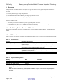
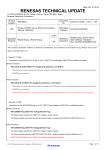
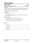
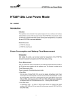
When the R_VBATT_Open() function is called, it checks whether or not the voltage monitoring 0 settings are correct
and whether or not a callback function was specified and if there is a problem, it returns an error and terminates
function execution. If the argument settings are valid, it sets up the VBATT pin voltage drop detection function
according to the settings in the configuration file (r_vbatt_rx_config.h) configuration options. After that it checks if the
battery backup voltages (the VCC and VBATT pins) have fallen (the VBATTSR register VBATRLVDETF bits) and
performs the following processing according to that result.
If a battery backup voltage drop has been detected, it calls the callback function with VBATT_DROP_VOLTAGE as
the argument. After calling the callback function, it sets the battery backup voltage drop detection flag to 0 (battery
backup voltage drop not detected).
If no battery backup voltage drop was detected, it calls the callback function with VBATT_NOT_DROP_VOLTAGE as
the argument.
Figure 1.1 shows the flowchart of the R_VBATT_Open() function.
See section 2.6, Compile Time Settings, and section 2.9, Callback Functions, for details on the configuration file
options and macro definitions used as callback function arguments.
R01AN2796EJ0101 Rev.1.01
Aug 31, 2015
Page 3 of 26
RX Family
Battery Backup Function Module Firmware Integration Technology
[Argument]
vbatt_info_t*
R_VBATT_Open
Is voltage monitoring
0 reset enabled and voltage detection
0 level 2.51 V?*
p_vbatt_info: Battery backup function callback function information
No (The OFS1 LVDAS bit is 1 or the OFS1 VDSEL[1:0]
field is a value other than 10b.)*
Yes (The OFS1 LVDAS bit is 0 and
the OFS1 VDSEL[1:0] field is 10b.)*
return(VBATT_ERR_LVD0_SETTING)
No (No callback function was specified)
Is a callback function specified
in the argument?
Yes (A callback function was set up)
return(VBATT_ERR_INVALID_ARG)
The follow settings are performed according to the settings in the configuration file
(r_vbatt_rx_config.h) configuration options.
Set up VBATT pin voltage drop
detection function
• The VBATT pin voltage drop detection level is set according to the
VBATT_CFG_DETECT_LEVEL setting.
• The VBATT pin voltage drop detection is enabled or disabled according to the
VBATT_CFG_DETECT_FUNCTION setting.
• The VBATT pin voltage drop detection interrupt is set up according to the
VBATT_CFG_DETECT_FUNCTION and VBATT_CFG_INT_PRIORITY settings.
No (The VBATTSR register VBATRLVDETF bit is 0)
Battery backup voltage
drop detected?
Yes (The VBATTSR register VBATRLVDETF bit is 1)
[Argument]
VBATT_DROP_VOLTAGE
(Battery backup voltage drop
detection performed)
Callback function
Set battery backup voltage drop
detection flag to 0
Callback function
[Argument]
VBATT_NOT_DROP_VOLTAGE
(Battery backup voltage drop
detection not performed)
Sets the VBATTSR register
VBATRLVDETF bit to 0.
return(VBATT_SUCCESS)
Note: * For the RX231 microcontroller.
Figure 1.1 R_VBATT_Open() Function Flowchart
R01AN2796EJ0101 Rev.1.01
Aug 31, 2015
Page 4 of 26
RX Family
Battery Backup Function Module Firmware Integration Technology
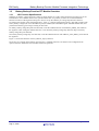
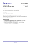
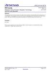
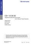
When the R_VBATT_Control() function is called, it checks whether or not the argument values are correct and, and if
there is a problem, it returns an error and terminates function execution. If the argument settings are valid, it sets the
VBATT pin voltage drop detection function enabled/disabled state and the detection level, and it sets up the interrupt,
according to the values set in the arguments.
Figure 1.2 shows the flowchart of the R_VBATT_Control() function.
R_VBATT_Control
Argument values OK?
[Argument]
vbatt_ctrl_info_t *
p_vbatt_ctrl_info: VBATT pin voltage drop detection
function setting information
No (The argument values are incorrect.)
Yes (The argument values are allowable.)
Set up VBATT pin voltage drop
detection function
return(VBATT_ERR_INVALID_ARG)
Performs the follow settings according to the values set in the argument.
• Enables or disables the battery backup function according to
the p_vbatt_ctrl_info -> vbatt_ctrl.bit.func value.
• Enables or disables VBATT pin voltage drop detection according to
the p_vbatt_ctrl_info -> vbatt_ctrl.bit.lvd_detect value.
• Sets the VBATT pin voltage drop detection level according to the
p_vbatt_ctrl_info -> vbatt_ctrl.bit.lvd_level value.
return(VBATT_SUCCESS)
• Sets up the VBATT pin voltage drop detection interrupt according to
the p_vbatt_ctrl_info -> vbatt_ctrl.bit.lvd_detect and p_vbatt_ctrl_info ->
vbatt_int_priority values.
Figure 1.2 R_VBATT_Control() Function Flowchart
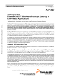
When the R_VBATT_GetStatus() function is called, it determines if VBATT pin voltage drop detection is enabled and
if whether or not the argument values are correct and, and if there is a problem, it returns an error and terminates
function execution. If the argument settings are valid, it reads out the value of the VBATT status register (VBATTSR).
The read out value is stored at the address received as an argument.
Figure 1.3 shows the flowchart of the R_VBATT_GetStatus() function.
R_VBATT_GetStatus
Battery backup function enabled?
[Argument]
vbatt_status_t*
p_vbatt_status: Battery backup function status information
No (The VBATTCR register VBTLVDEN bit is 0)
Yes (The VBATTCR register VBTLVDEN bit is 1)
Read VBATT status register
return(VBATT_ERR_FUNC_INVALID)
Stores the value read from the VBATT status register
in the address (p_vbatt_status) passed as an argument.
return(VBATT_SUCCESS)
Figure 1.3 R_VBATT_GetStatus() Function Flowchart
R01AN2796EJ0101 Rev.1.01
Aug 31, 2015
Page 5 of 26
RX Family
1.3.2
Battery Backup Function Module Firmware Integration Technology
Interrupt Specifications
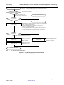
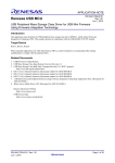
When the interrupt used when a VBATT pin voltage drop is set to be a maskable interrupt, when this maskable interrupt
occurs, the callback function is called with VBATT_MASKABLE_INTERRUPT as the argument.
Figure 1.4 shows the flowchart of the r_vbatt_isr() function.
r_vbatt_isr
Callback function
[Argument]
VBATT_MASKABLE_INTERRUPT
(When a maskable interrupt occurred)
return
Figure 1.4 r_vbatt_isr() Function Flowchart
When the interrupt used when a VBATT pin voltage drop is set to be a nonmaskable interrupt, when this nonmaskable
interrupt occurs, the callback function is called with VBATT_NON_MASKABLE_INTERRUPT as the argument.
Figure 1.5 shows the flowchart of the r_vbatt_nmi_isr() function.
r_vbatt_nmi_isr
Callback function
[Argument]
VBATT_NON_MASKABLE_INTERRUPT
(When a nonmaskable interrupt occurred)
return
Figure 1.5 r_vbatt_nmi_isr() Function Flowchart
R01AN2796EJ0101 Rev.1.01
Aug 31, 2015
Page 6 of 26
RX Family
1.4
Battery Backup Function Module Firmware Integration Technology
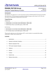
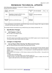
Usage Example
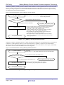
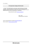
Call the R_VBATT_Open() function immediately after the reset start. The callback function should perform processing
based on the value of its arguments.
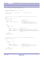
Table 1.3 lists the callback function’s arguments and processing that should be performed, and figure 1.6 shows a usage
example of the battery backup function FIT module.
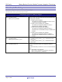
Table 1.3 Callback Function’s Arguments and Processing that Should be Performed
Argument
Processing that
Should be
Performed
Reason
VBATT_NOT_DROP_VOLTAGE
VBATT_DROP_VOLTAGE
(Battery backup voltage drop
detection not performed)
(Battery backup voltage drop
detection performed)
Reset the RAM and RTC registers
as required.
The real-time clock must be
initialized.
Operations such as displaying a warning
When the battery backup supply
When the battery backup
This interrupt occurs when the supply
voltage has not dropped, the value
supply voltage drops, the
voltage on the VBATT pin falls. Processing
of the RTC register will be saved,
real-time clock registers and
but RAM and the RTC interrupt
RAM go to their values after
to handle the situation where the VBATT pin
supply voltage has fallen can be performed.
registers will be set to their post-
a reset. Therefore
initialization is required.
reset values. Therefore, the RAM
VBATT_MASKABLE_INTERRUPT
VBATT_NON_MASKABLE_INTERRUPT
(VBATT pin voltage drop detection interrupt)
that the external battery level is low and
backing up data should be performed.
and RTC interrupt register values
must be set again.
Reset start
Set up data structure
Battery backup function
setup function
R_VBATT_Open()
Stores the address of the callback function
in the data structure.
Calls the R_VBATT_Open() function.
Main user program
Callback function
Argument
When the battery backup supply voltage has not fallen, the
real-time clock registers will be saved, but RAM returns to its
post-reset values.
If necessary, the RAM content should be restored here.
When the battery backup supply voltage has fallen, both the
real-time clock registers and RAM will return to their post-reset
values.
The application should initialize the real-time clock here.
This is called by the interrupt* that occurs when the VBATT pin
supply voltage (external battery or other source) falls.
The application should perform operations such as displaying a
warning that the battery level is low and backing up data.
Note: * Only when interrupts are enabled.
The following two items must be set up independently.
(1) The VBATT pin must be connected to a power supply that is
independent of VCC.
(2) Enable the voltage monitoring 0 reset and set the voltage
detection 0 circuit's voltage detection level.
If the RX231 is used, set the following two
BSP_CFG_OFS1_REG_VALUE items in the BSP
configuration file (r_bsp_config.h).
Set b1-b0 to 10b. (This selects 2.51 V as the voltage
detection 0 level.)
Set b2 to 0. (This enables the voltage monitoring 0 reset.)
The factor that caused the callback function to be
called can be determined from its arguments.
The callback function should perform processing
appropriate to the factor by checking its arguments.
VBATT_NOT_DROP_VOLTAGE
(Battery backup voltage drop detection not performed)
Restore RAM values and other operations
Reset the values in RAM
if required.
VBATT_DROP_VOLTAGE
(Battery backup voltage drop detection performed)
Real-time clock initialization
and other operations
Initialize the real-time
clock.
VBATT_MASKABLE_INTERRUPT or
VBATT_NON_MASKABLE_INTERRUPT
(VBATT pin voltage drop detection interrupt)
VBATT pin voltage drop warning display
and other operations
Display a warning that the
VBATT pin voltage has
dropped and perform any other
appropriate operations.
return
Program example
Figure 1.6 Usage Example of the Battery Backup Function FIT Module
R01AN2796EJ0101 Rev.1.01
Aug 31, 2015
Page 7 of 26
RX Family
2.
Battery Backup Function Module Firmware Integration Technology
API Information
The sample code provided with this application note has been confirmed to operate under the following conditions.
2.1
Hardware Requirements
The microcontroller used must support the following function.
• Battery backup function
2.2
Software Requirements
This driver depends on the following packages.
• r_bsp
2.3
Supported Tool Chain
This driver has been confirmed to operate under the following tool chain.
• Renesas RX Toolchain v.2.03.00 (RX231, RX230)
2.4
Header Files
All the AP calls and the interface definitions required to support those calls are coded in the file r_vbatt_rx_if.h.
2.5
Integer Types
This project is coded in ANSI C99. These types are defined in stdint.h.
R01AN2796EJ0101 Rev.1.01
Aug 31, 2015
Page 8 of 26
RX Family
2.6
Battery Backup Function Module Firmware Integration Technology
Compile Time Settings
This module configuration options are set in r_vbatt_rx_config.h.
The table below lists the option names and set values.
Configuration options in r_vbatt_rx_config.h
#define VBATT_CFG_DETECT_FUNCTION
Note: The default value is
"VBATT_DTCT_DISABLE"
Selects whether or not the VBATT pin voltage drop detection
function is used. This also selects the interrupt generated when
a voltage drop is detected.
For VBATT_DTCT_DISABLE:
The VBATT pin voltage drop detection function is set to
invalid and the interrupt is disabled.
For VBATT_DTCT_ENABLE_INT_DISABLE:
The VBATT pin voltage drop detection function is
enabled and the interrupt is disabled.
For VBATT_DTCT_ENABLE_NMI_ENABLE:
The VBATT pin voltage drop detection function is
enabled and the nonmaskable interrupt is enabled as the
interrupt.
For VBATT_DTCT_ENABLE_INT_ENABLE:
#define VBATT_CFG_DETECT_LEVEL
Note: The default value is
"VBATT_DTCT_LEVEL_2_20_V"
#define VBATT_CFG_INT_PRIORITY
Note: The default value is "5"
R01AN2796EJ0101 Rev.1.01
Aug 31, 2015
The VBATT pin voltage drop detection function is
enabled and the maskable interrupt is enabled as the
interrupt.
The VBATT pin voltage drop detection level can be selected.
For VBATT_DTCT_LEVEL_2_20_V, the detection level is
set to 2.20 V.
For VBATT_DTCT_LEVEL_2_00_V, the detection level is
set to 2.00 V.
The interrupt priority level can be selected when a maskable
interrupt is used as the VBATT pin voltage drop detection
interrupt.
The value selected by a value from 1 to 15 is set as the interrupt
level.
Note: This setting is only valid when
VBATT_DTCT_ENABLE_INT_ENABLE is selected by
VBATT_CFG_DETECT_FUNCTION.
Page 9 of 26
RX Family
2.7
Battery Backup Function Module Firmware Integration Technology
Arguments
This section presents the structures used as arguments to the API functions. These structures are included in the file
r_vbatt_rx_if.h along with the API function prototype declarations.
/* Battery backup function data structure */
typedef volatile struct
{
vbatt_callback_t
callbackfunc;
/* Callback function */
} vbatt_info_t;
/* Structure used to set up the VBATT pin voltage drop detection function
again */
typedef volatile struct
{
uint8_t rsv2;
/* Reserved area */
uint8_t rsv1;
/* Reserved area */
uint8_t vbatt_int_priority;
/* Interrupt priority level for
the VBATT pin voltage drop detection
interrupt (maskable interrupt) */
union
{
uint8_t byte;
struct
{
uint8_t rsv:3;
/* Reserved area */
uint8_t lvd_level:2; /* VBATT pin voltage drop detection level */
uint8_t lvd_detect:2;/* VBATT pin voltage drop detection function */
uint8_t func:1;
/* Enabled/disabled state of the battery backup
function */
} bit;
} vbatt_ctrl;
} vbatt_ctrl_info_t;
/* Structure used to hold the state
typedef volatile struct
{
union
{
uint8_t
byte;
struct
{
uint8_t rsv:6;
uint8_t vbatt_mon:1;
uint8_t pwr_drp_dtct:1;
} bit;
} vbatt_status;
} vbatt_status_t;
R01AN2796EJ0101 Rev.1.01
Aug 31, 2015
of the battery backup function */
/* Reserved area */
/* VBATT pin voltage monitor flag */
/* Battery backup supply voltage drop
detection flag */
Page 10 of 26
RX Family
2.8
Battery Backup Function Module Firmware Integration Technology
Return Values
This section presents the return values from the API functions. This enumeration type is defined in the file
r_vbatt_rx_if.h along with the API function prototype declarations.
typedef enum
{
/* Return value used for calls to battery backup
API functions */
/* Processing completed without problem */
/* The function was called multiple times */
(Not implemented)
VBATT_ERR_LVD0_SETTING, /* Illegal voltage monitoring 0 settings in
option function selection register 1 (OFS1) */
VBATT_ERR_INVALID_ARG, /* Invalid argument */
VBATT_ERR_FUNC_INVALID, /* R_VBATT_GetStatus() was called when VBATT pin
voltage drop detection was invalid */
VBATT_ERR_OTHER
/* Other error */
} vbatt_return_t;
2.9
VBATT_SUCCESS,
VBATT_ERR_LOCK_FUNC,
Callback Function
In this module, a callback function is called when the R_VBATT_Open() function is called or when an interrupt occurs.
The callback function takes an argument whose set value determines whether a battery backup voltage drop was
detected, or whether it was called from an interrupt handler when the VBATT pin voltage fell.
Table 2.1 lists the constant definitions (enum vbatt_cb_evt_t) for the argument passed to the callback function.
For callback function setup, the address of the callback function to be registered should be stored in “callbackfunc”
member in the structure described in section 2.7, Arguments.
Table 2.1 Definitions of Constants Passed as an Argument to the Callback Function
(enum vbatt_cb_evt_t)
Defined Constant
VBATT_NOT_DROP_VOLTAGE
VBATT_DROP_VOLTAGE
VBATT_MASKABLE_INTERRUPT
VBATT_NON_MASKABLE_INTERRUPT
R01AN2796EJ0101 Rev.1.01
Aug 31, 2015
Conditions for Passing as an Argument
When R_VBATT_Open() was called in the state where a
battery backup supply voltage drop was not detected
(the VBATTSR register VBATRLVDETF bit was 0)
When R_VBATT_Open() was called in the state where a
battery backup supply voltage drop was detected
(the VBATTSR register VBATRLVDETF bit was 1)
When a maskable interrupt due to a voltage drop on the
VBATT pin occurred
When a nonmaskable interrupt due to a voltage drop on the
VBATT pin occurred
Page 11 of 26
RX Family
2.10
Battery Backup Function Module Firmware Integration Technology
Fit Module Addition Methods
This module must be added to each project used in e2 studio.
There are two methods for adding to a project: using the FIT plug-in and adding manually.
When the FIT plug-in is used, FIT modules can be added to projects easily and the include file path will be updated
automatically. Therefore we recommend using the FIT plug-in when adding FIT modules to a project.
For details on the method for addition FIT modules using the FIT plug-in, see section 2., Adding FIT Modules to e2
studio Projects Using FIT Plug-In, in the “Adding Firmware Integration Technology Modules to Projects
(R01AN1723EU)” application note.
See section 3, Adding FIT Modules to e2 studio Projects Manually, for adding the FIT module by hand without using
the FIT plugin.
When this FIT module is used, the Board Support Package FIT module (BSP module) must also be added to the project.
See the Board Support Package Module Using Firmware Integration Technology (R01AN1685EU) application note for
the methods for adding the BSP module.
R01AN2796EJ0101 Rev.1.01
Aug 31, 2015
Page 12 of 26
RX Family
3.
Battery Backup Function Module Firmware Integration Technology
API Functions
3.1
R_VBATT_Open()
This function sets up the VBATT pin voltage drop detection function and determines whether or not the battery backup
supply voltage has fallen.
This function is called once and only once after a reset start. The processing performed when a drop in the battery
backup supply voltage is detected and when no drop is detected are performed by a callback function called by this
function.
Format
vbatt_return_t R_VBATT_Open (
vbatt_info_t *
p_vbatt_info
)
Parameters
p_vbatt_info
Pointer to a data structure for the battery backup information.
The following members are used by this function. See section 2.7, Arguments, for details on this structure.
vbatt_callback_t
callbackfunc;
/* Address of the callback function */
Return Values
VBATT_SUCCESS
VBATT_ERR_LVD0_SETTING
VBATT_ERR_INVALID_ARG
/* Processing completed without problem */
/* Illegal voltage monitoring 0 settings in
option function selection register 1 (OFS1) */
/* Invalid argument */
Properties
A prototype declaration for this function appears in r_vbatt_rx_if.h.
Description
This function sets the enabled or disabled state of the VBATT pin voltage drop detection function, the detection level,
and the interrupts according to settings in the configuration options. After that, it determines whether or not the battery
backup supply voltage has dropped and calls the callback function.
When calling the callback function:
• If a battery backup supply voltage drop has not been detected:
A pointer to a variable that has been set to VBATT_NOT_DROP_VOLTAGE is passed as an argument.
• If a battery backup supply voltage drop has been detected:
A pointer to a variable that has been set to VBATT_DROP_VOLTAGE is passed as an argument.
Reentrant
This function is not reentrant.
R01AN2796EJ0101 Rev.1.01
Aug 31, 2015
Page 13 of 26
RX Family
Battery Backup Function Module Firmware Integration Technology
Example
#include "r_vbatt_rx_if.h"
void vbatt_callback(vbatt_cb_evt_t * vbatt_cb_event);
void main(void)
{
vbatt_return_t
vbatt_info_t
ret;
vbatt_info;
vbatt_info.callbackfunc = vbatt_callback;
ret = R_VBATT_Open(&vbatt_info);
if (VBATT_SUCCESS != ret)
{
/* Please do the processing at the time of the error */
}
while(1);
}
void vbatt_callback(vbatt_cb_evt_t * vbatt_cb_event)
{
switch(*vbatt_cb_event)
{
/* Battery backup power voltage drop not detected */
case VBATT_NOT_DROP_VOLTAGE:
/* Please set RAM again as needed */
break;
/* Battery backup power voltage drop detected */
case VBATT_DROP_VOLTAGE:
/* Please initialize the Realtime Clock */
break;
/* VBATT voltage drop detected interrupt */
case VBATT_MASKABLE_INTERRUPT:
case VBATT_NON_MASKABLE_INTERRUPT:
/* Please process warning indication, backup, etc. */
break;
default:
/* Do nothing */
}
}
break;
R01AN2796EJ0101 Rev.1.01
Aug 31, 2015
Page 14 of 26
RX Family
Battery Backup Function Module Firmware Integration Technology
Special Notes
None
R01AN2796EJ0101 Rev.1.01
Aug 31, 2015
Page 15 of 26
RX Family
3.2
Battery Backup Function Module Firmware Integration Technology
R_VBATT_Control()
This function sets the enabled or disabled state of the battery backup function and sets up the VBATT pin voltage drop
detection function. This function is used when changing the content of these settings from those made with the
R_VBATT_Open() function.
Format
vbatt_return_t
R_VBATT_Control (
vbatt_ctrl_info_t *
p_vbatt_ctrl_info
)
Parameters
p_vbatt_ctrl_info
Pointer to the data structure used by the VBATT pin voltage drop detection function.
The following members are used by this function. See section 2.7, Arguments, for details on this structure.
typedef volatile struct
{
uint8_t rsv2;
uint8_t rsv1;
uint8_t vbatt_int_priority;
union
{
uint8_t
byte;
struct
{
uint8_t rsv:3;
uint8_t lvd_level:2;
uint8_t lvd_detect:2;
uint8_t func:1;
} bit;
} vbatt_ctrl;
} vbatt_ctrl_info_t;
/* Reserved area */
/* Reserved area */
/* Interrupt priority level for
the VBATT pin voltage drop detection
interrupt (maskable interrupt) */
/*
/*
/*
/*
Reserved area */
VBATT pin voltage drop detection level */
VBATT pin voltage drop detection function */
Enabled/disabled state of the battery backup
function */
Return Values
VBATT_SUCCESS
VBATT_ERR_INVALID_ARG
/* Processing completed without problem */
/* Invalid argument */
Properties
A prototype declaration for this function appears in r_vbatt_rx_if.h.
R01AN2796EJ0101 Rev.1.01
Aug 31, 2015
Page 16 of 26
RX Family
Battery Backup Function Module Firmware Integration Technology
Description
This function sets the enabled or disabled state of the battery backup function, the enabled or disabled state of the
VBATT pin voltage drop detection function, the detection level, and the interrupts according to the settings of the
arguments.
Reentrant
This function is not reentrant.
Example
#include "r_vbatt_rx_if.h"
void main(void)
{
vbatt_return_t
vbatt_ctrl_info_t
ret;
vbatt_ctrl_info;
/* Battery backup function enable */
vbatt_ctrl_info.vbatt_ctrl.bit.func = 1;
/* VBATT drop detect function enable and maskable interrupt enable */
vbatt_ctrl_info.vbatt_ctrl.bit.lvd_detect = VBATT_DTCT_ENABLE_INT_ENABLE;
/* VBATT drop detect level is 2.00V */
vbatt_ctrl_info.vbatt_ctrl.bit.lvd_level = VBATT_DTCT_LEVEL_2_00_V;
/* interrupt priority level is 7*/
vbatt_ctrl_info.vbatt_int_priority = 7;
ret = R_VBATT_Control(&vbatt_ctrl_info);
if (VBATT_SUCCESS != ret)
{
/* Please do the processing at the time of the error */
}
}
while(1);
R01AN2796EJ0101 Rev.1.01
Aug 31, 2015
Page 17 of 26
RX Family
Battery Backup Function Module Firmware Integration Technology
Special Notes
The table below lists and describes the range of values the arguments may be set to and the meanings of those
arguments.
Structure (vbatt_ctrl_info_t)
Member
Bit
Allowable Range
Meaning
vbatt_ctrl
func
0 to 1
The enabled or disabled state of the battery backup function
can be changed.
0: The battery backup function is disabled.
1: The battery backup function is enabled.
lvd_detect
Selected from
macro definitions for
the corresponding
meaning
Selects whether or not the VBATT pin voltage drop detection
function is used. This also selects the interrupt generated
when a voltage drop is detected.
For VBATT_DTCT_DISABLE:
The VBATT pin voltage drop detection function is set
to invalid and the interrupt is disabled.
For VBATT_DTCT_ENABLE_INT_DISABLE:
The VBATT pin voltage drop detection function is
enabled and the interrupt is disabled.
For VBATT_DTCT_ENABLE_NMI_ENABLE:
The VBATT pin voltage drop detection function is
enabled and the nonmaskable interrupt is enabled as
the interrupt.
For VBATT_DTCT_ENABLE_INT_ENABLE:
vbatt_int_priority
lvd_level
Selected from
macro definitions for
the corresponding
meaning
1 to 15
R01AN2796EJ0101 Rev.1.01
Aug 31, 2015
The VBATT pin voltage drop detection function is
enabled and the maskable interrupt is enabled as the
interrupt.
The VBATT pin voltage drop detection level can be selected.
For VBATT_DTCT_LEVEL_2_20_V, the detection level is
set to 2.20 V.
For VBATT_DTCT_LEVEL_2_00_V, the detection level is
set to 2.00 V.
The interrupt priority level can be selected when a maskable
interrupt is used as the VBATT pin voltage drop detection
interrupt.
The value selected by a value from 1 to 15 is set as the
interrupt level.
Note: This setting is only valid when
VBATT_DTCT_ENABLE_INT_ENABLE is selected by
lvd_detect.
Page 18 of 26
RX Family
3.3
Battery Backup Function Module Firmware Integration Technology
R_VBATT_GetStatus()
This function acquires the status for the battery backup function. This function is used to check the status of the battery
backup function.
Format
vbatt_return_t
R_VBATT_GetStatus (
vbatt_status_t *
p_vbatt_status
)
Parameters
p_vbatt_status
Pointer to a variable to hold the battery backup function status.
The following members are used by this function. See section 2.7, Arguments, for details on this structure.
typedef volatile struct
{
union
{
uint8_t
byte;
struct
{
uint8_t rsv:6;
uint8_t vbatt_mon:1;
uint8_t pwr_drp_dtct:1;
} bit;
} vbatt_status;
} vbatt_status_t;
/* Reserved area */
/* VBATT pin voltage monitor flag */
/* Battery backup supply voltage drop
detection flag */
Return Values
VBATT_SUCCESS
VBATT_ERR_INVALID_ARG
VBATT_ERR_FUNC_INVALID
/* Processing completed without problem */
/* Invalid argument */
/* R_VBATT_GetStatus() was called when VBATT pin
voltage drop detection was invalid */
Properties
A prototype declaration for this function appears in r_vbatt_rx_if.h.
Description
This function reads out the VBATT status register (VBATTSR) to acquire the status of the battery backup function. It
then stores that information at the address passed as an argument.
Reentrant
This function is reentrant.
R01AN2796EJ0101 Rev.1.01
Aug 31, 2015
Page 19 of 26
RX Family
Battery Backup Function Module Firmware Integration Technology
Example
#include "r_vbatt_rx_if.h"
void main(void)
{
vbatt_return_t
vbatt_status_t
vbatt_ctrl_info_t
ret;
vbatt_status;
vbatt_ctrl_info;
/* VBATT drop detect function enable */
vbatt_ctrl_info.vbatt_ctrl.bit.func = 1;
vbatt_ctrl_info.vbatt_ctrl.bit.lvd_detect = VBATT_DTCT_ENABLE_INT_DISABLE;
vbatt_ctrl_info.vbatt_ctrl.bit.lvd_level = VBATT_DTCT_LEVEL_2_20_V;
vbatt_ctrl_info.vbatt_int_priority = 5;
ret = R_VBATT_Control(&vbatt_ctrl_info);
if (VBATT_SUCCESS != ret)
{
/* Please do the processing at the time of the error */
}
/* gets the state of the battery backup function */
ret = R_VBATT_GetStatus(&vbatt_status);
if (VBATT_SUCCESS != ret)
{
/* Please do the processing at the time of the error */
}
}
while(1);
Special Notes
The table below shows the layout of the status flags.
Bit
Bit Name
b7 to b2
Reserved area
b1
VBATT pin voltage monitor flag
Symbol
Function
rsv
Undefined
vbatt_mon
0: VBATT < Vdetvbt
1: VBATT ≥ Vdetvbt or the VBATT
detection function was disabled.
R01AN2796EJ0101 Rev.1.01
Aug 31, 2015
b0
Battery backup supply voltage
drop detection flag
pwr_drp_dtct
0: Battery backup supply voltage
drop not detected
1: Battery backup supply voltage
drop detected
Page 20 of 26
RX Family
3.4
Battery Backup Function Module Firmware Integration Technology
R_VBATT_GetVersion()
This function returns the version number of the API.
Format
uint32_t R_VBATT_GetVersion(void)
Parameters
None
Return Values
Version number
Properties
A prototype declaration for this function appears in r_vbatt_rx_if.h.
Description
This function returns the version number of this API.
Reentrant
This function is reentrant.
Example
uint32_t
version;
version = R_VBATT_GetVersion();
Special Notes
This function can be compiled in line by using the "#pragma inline" directive.
R01AN2796EJ0101 Rev.1.01
Aug 31, 2015
Page 21 of 26
RX Family
4.
4.1
Battery Backup Function Module Firmware Integration Technology
Sample Code
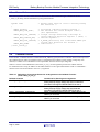
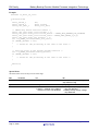
Example of Use Combined with the RTC FIT Module
This sample code shows the use of the battery backup function FIT module in combination with the RTF FIT module,
which is used for real-time clock settings.
The configuration options are set as follows.
• The BSP FIT module BSP_CFG_OFS1_REG_VALUE is set to 0xFFFFFFFA.
• The default values are used for the RTC FIT module and the VBATT FIT module settings.
This sample code operates in the sequence (1) to (3) shown below.
(1) The R_VBATT_Open() function is called.
(The callback function is called when the R_VBATT_Open() function is called.)
(2) The callback function for the battery backup function sets up the RTC according to whether or not a battery backup
supply voltage drop is detected. Whether or not there is a battery backup supply voltage drop is recognized from the
arguments to the callback function.
(2-A) If the callback function argument is VBATT_NOT_DROP_VOLTAGE, the RTC FIT module is set up again
using the R_RTC_Open() and R_RTC_Read() functions.
(2-B) If the callback function argument is VBATT_DROP_VOLTAGE, the R_RTC_Open() function is used to
initialize the RTC.
(3) In the RTC periodic interrupt callback function, the R_RTC_Read() function is used to read out the current time.
The read out time is displayed on the debugging console.
#include <stdio.h>
#include "r_rtc_rx_if.h"
#include "r_vbatt_rx_if.h"
/* This is required because printf() is used for debugging display. */
static void vbatt_callback(vbatt_cb_evt_t * vbatt_cb_event);
static void rtc_callback(void *event);
static tm_t rtc_curr_time;
void main(void)
{
vbatt_return_t
vbatt_info_t
/* Data structure used to store the current time from the RTC. */
ret;
vbatt_info;
vbatt_info.callbackfunc = vbatt_callback;
/* For confirming the return value from the API function. */
/* Data structure for the battery backup function */
/* Callback function setup */
/* VBATT pin voltage detection function setup and battery backup supply voltage drop determination. */
ret = R_VBATT_Open(&vbatt_info);
if (VBATT_SUCCESS != ret)
{
Executing this function results in the set up callback function
while(1);
(vbatt_callback()) being called.
}
}
while(1);
/* Battery backup function callback function */
static void vbatt_callback(vbatt_cb_evt_t * vbatt_cb_event)
{
rtc_err_t
ret;
/* For confirming the return value from the API function. */
rtc_init_t rtc_info;
/* RTC data structure */
Figure 4.1 Usage Example in Combination with the RTC FIT Module (1/3)
R01AN2796EJ0101 Rev.1.01
Aug 31, 2015
Page 22 of 26
RX Family
Battery Backup Function Module Firmware Integration Technology
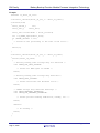
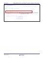
/* Discriminate based on the argument */
switch(*vbatt_cb_event)
{
/* If no battery backup supply voltage drop is detected. */
case VBATT_NOT_DROP_VOLTAGE:
/* Set up the RTC data structure again */
rtc_info.output_freq = RTC_OUTPUT_OFF;
/* Stop RTCOUT output */
rtc_info.periodic_freq = RTC_PERIODIC_1_HZ;
/* RTC periodic interrupt generation period: 1 second */
rtc_info.periodic_priority = 8;
/* Interrupt priority level */
rtc_info.set_time = false;
/* Do not update the RTC clock counter I/O register. */
rtc_info.p_callback = rtc_callback;
/* Callback function setup */
/* RTC re-setup */
ret = R_RTC_Open(&rtc_info, &rtc_curr_time);
if (RTC_SUCCESS != ret)
{
while(1);
}
Although the RTC I/O register is saved, RAM
and other registers are reset.
Therefore, the RTC FIT module is setup again.
/* Read out the current time information from the RTC clock counter I/O register
and store it in the data structure. */
ret = R_RTC_Read(&rtc_curr_time, NULL);
if (RTC_SUCCESS != ret)
Since the RTC I/O register is saved, the current
{
time information is read from the RTC I/O register
while(1);
}
by the R_RTC_Read() function and stored again in
the data structure.
break;
/* When a battery backup supply voltage drop was
case VBATT_DROP_VOLTAGE:
/* RTC data structure setup */
rtc_info.output_freq = RTC_OUTPUT_OFF;
rtc_info.periodic_freq = RTC_PERIODIC_1_HZ;
rtc_info.periodic_priority = 8;
rtc_info.set_time = true;
rtc_info.p_callback = rtc_callback;
detected */
/*
/*
/*
/*
/*
Stop RTCOUT output */
RTC periodic interrupt generation period: 1 second */
Interrupt priority level */
Update the RTC clock counter I/O register. */
Callback function setup */
/* Set the current time information structure time setting to "2015-06-30 12:34:56" */
rtc_curr_time.tm_sec
= 56;
/* Seconds (0 - 59) */
rtc_curr_time.tm_min
= 34;
/* Minutes (0 - 59) */
rtc_curr_time.tm_hour = 12;
/* Hours (0 - 23) */
rtc_curr_time.tm_mday = 30;
/* Day (1 - 31) */
rtc_curr_time.tm_mon
= 6;
/* Month (0 - 11, 0 = January) */
rtc_curr_time.tm_year = 115;
/* Year (referenced to 1900) */
rtc_curr_time.tm_wday = 0;
/* Day of week (0 - 6, 0 = Sunday) */
rtc_curr_time.tm_yday = 0;
/* Day in year (0 - 365) */
rtc_curr_time.tm_isdst = 0;
/* Daylight saving time in effect (> 0),
not in effect (= 0). */
/* RTC initialization */
ret = R_RTC_Open(&rtc_info, &rtc_curr_time);
if (RTC_SUCCESS != ret)
If a battery backup supply voltage drop was detected,
{
the microcontroller is in a state where RTC operation is
while(1);
}
guaranteed. Therefore the RTC is reinitialized.
not
break;
/* Interrupt due to VBATT pin voltage drop */
case VBATT_MASKABLE_INTERRUPT:
case VBATT_NON_MASKABLE_INTERRUPT:
/* Unused in this sample code */
break;
}
}
default:
/* No processing */
break;
Figure 4.2 Usage Example in Combination with the RTC FIT Module (2/3)
R01AN2796EJ0101 Rev.1.01
Aug 31, 2015
Page 23 of 26
RX Family
Battery Backup Function Module Firmware Integration Technology
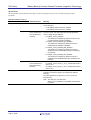
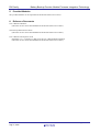
/* RTC callback function */
static void rtc_callback(void *event)
{
rtc_err_t ret;
/* For confirming the return value from the API function. */
/* For a periodic interrupt */
if (*(rtc_cb_evt_t *)event == RTC_EVT_PERIODIC)
{
/* For a periodic interrupt */
/* Read out the current time information from the RTC clock counter I/O register
and store it in the data structure. */
ret = R_RTC_Read(&rtc_curr_time, NULL);
if (RTC_SUCCESS != ret)
Each time a period interrupt occurs
{
the current time is read out.
while(1);
}
}
}
(at 1-second intervals)
/* Display on the debugging console. */
printf("%d/%d/%d %02d:%02d:%02d\n",
rtc_curr_time.tm_year + 1900,
rtc_curr_time.tm_mon,
rtc_curr_time.tm_mday,
rtc_curr_time.tm_hour,
rtc_curr_time.tm_min,
rtc_curr_time.tm_sec);
Figure 4.2 Usage Example in Combination with the RTC FIT Module (3/3)
R01AN2796EJ0101 Rev.1.01
Aug 31, 2015
Page 24 of 26
RX Family
5.
Battery Backup Function Module Firmware Integration Technology
Provided Modules
The provided modules can be acquired from the Renesas Electronics web site.
6.
Reference Documents
User’s Manual: Hardware
(The latest version can be downloaded from the Renesas Electronics website.)
Technical Update/Technical News
(The latest version can be downloaded from the Renesas Electronics website.)
User’s Manual: Development Tools
RX Family C/C++ Compiler CC-RX V2.03.00 User’s Manual (R20UT3248EJ)
(The latest version can be downloaded from the Renesas Electronics website.)
R01AN2796EJ0101 Rev.1.01
Aug 31, 2015
Page 25 of 26
RX Family
Battery Backup Function Module Firmware Integration Technology
Related Technical Updates
This module reflects the content of the following technical updates.
None
Website and Support
Renesas Electronics Website
http://www.renesas.com/
Inquiries
http://www.renesas.com/contact/
All trademarks and registered trademarks are the property of their respective owners.
R01AN2796EJ0101 Rev.1.01
Aug 31, 2015
Page 26 of 26
Revision History
Rev.
1.00
1.01
Date
Aug. 24, 2015
Aug. 31, 2015
Description
Page
Summary
—
First edition issued
Program
Modified the battery backup function FIT module due to the
iodefine.h (V1.0C) is updated.
[Description]
Compilations error occurs when the iodefine.h (V0.9E) is used.
[Workaround]
Please use rev.1.01 or a later version of the battery backup
function FIT module.
A-1
General Precautions in the Handling of MPU/MCU Products
The following usage notes are applicable to all MPU/MCU products from Renesas. For detailed usage notes on the
products covered by this document, refer to the relevant sections of the document as well as any technical updates that
have been issued for the products.
1. Handling of Unused Pins
Handle unused pins in accord with the directions given under Handling of Unused Pins in the manual.
The input pins of CMOS products are generally in the high-impedance state. In operation with an unused
pin in the open-circuit state, extra electromagnetic noise is induced in the vicinity of LSI, an associated
shoot-through current flows internally, and malfunctions occur due to the false recognition of the pin state as
an input signal become possible. Unused pins should be handled as described under Handling of Unused Pins
in the manual.
2. Processing at Power-on
The state of the product is undefined at the moment when power is supplied.
The states of internal circuits in the LSI are indeterminate and the states of register settings and pins are
undefined at the moment when power is supplied.
In a finished product where the reset signal is applied to the external reset pin, the states of pins
are not guaranteed from the moment when power is supplied until the reset process is completed.
In a similar way, the states of pins in a product that is reset by an on-chip power-on reset function
are not guaranteed from the moment when power is supplied until the power reaches the level at
which resetting has been specified.
3. Prohibition of Access to Reserved Addresses
Access to reserved addresses is prohibited.
The reserved addresses are provided for the possible future expansion of functions. Do not access these
addresses; the correct operation of LSI is not guaranteed if they are accessed.
4. Clock Signals
After applying a reset, only release the reset line after the operating clock signal has become stable.
When switching the clock signal during program execution, wait until the target clock signal has
stabilized.
When the clock signal is generated with an external resonator (or from an external oscillator) during a reset,
ensure that the reset line is only released after full stabilization of the clock signal. Moreover, when
switching to a clock signal produced with an external resonator (or by an external oscillator) while program
execution is in progress, wait until the target clock signal is stable.
5. Differences between Products
Before changing from one product to another, i.e. to a product with a different type number, confirm
that the change will not lead to problems.
The characteristics of an MPU or MCU in the same group but having a different part number may differ in
terms of the internal memory capacity, layout pattern, and other factors, which can affect the ranges of
electrical characteristics, such as characteristic values, operating margins, immunity to noise, and amount of
radiated noise. When changing to a product with a different part number, implement a system-evaluation test
for the given product.