1
DecoderPro3® User’s Guide
Version 3.4 8/21/2013 DecoderPro3®User’sGuide
DecoderPro3®Version3.4
Revised 8/21/2013 DecoderPro®3 is a Java‐based cross‐platform application for model railroaders. DecoderPro3 ® can run on any computer system that will run Java 1.6.0 or later, whether it is Macintosh, Windows, or Linux based. It does require that Java be installed on the computer. You can get Java as a free (but very large...) download at: java.sun.com/getjava/ Note: All screen shots in this manual are from a Windows machine using the "Metal" User Interface option, Your screens may differ in some layout details, they will be essentially the same. All programming examples shown are with Digitrax PR3 (MS100 mode) connected to Digitrax Super Chief Radio Command Station. Most of the decoders in locomotive samples will be Digitrax, except for sound examples. Note: This entire manual has been updated to correspond to JMRI® 3.4 DecoderPro3® only from the SHTML on line version. [Typetext]
Pageii
DecoderPro3®User’sGuide
Revisions
Version
Revision
Date
Editors
Major Revisions
2.14.1
2/26/2012 Dale A. Tripp
Bruce Shanks
Create DecoderPro 3® User's Guide
3.0
8/4/2012 Dale A. Tripp
Bruce Shanks
Update to version 3.0
3.2
1/12/2013 Dale A. Tripp
Update to version 3.2
3.4
8/21/2013 Dale A. Tripp
Update to version 3.4
[Typetext]
Pageiii
DecoderPro3®User’sGuide
TableofContents
DECODERPRO3®VERSION3.4
REVISIONS
II III INSTALLINGJMRI®
1 Preparing to Install JMRI® 1 Installing JMRI software 1 GETTINGSTARTEDWITHDECODERPRO3®
2 What is DCC? 2 What DCC systems will DecoderPro3® work with? 3 WHATHARDWAREDOINEED?
4 HOWDOISTARTTHEDECODERPRO3®PROGRAM?
5 For First Time User 5 Previous user If you are updating and DecoderPro® has been installed previously, then proceed here: 9 9 HOWDOISETUPMYPREFERENCES?
11 Connections Pane 13 Defaults Pane 15 File locations Pane 16 Start Up Pane 17 Display Panes GUI TAB Locale TAB Console TAB 19 19 20 20 Messages Panes 21 [Typetext]
Pageiv
DecoderPro3®User’sGuide
Roster Panes Programmer TAB Roster TAB 21 21 21 Throttle Pane 22 WiThrottle Pane 22 JSON Server Pane 23 Web Server Pane 23 You must restart DecoderPro for preferences to take effect 24 HOWDOISETUPTOPROGRAMADECODER?
25 Adding New Locomotive THEBASICPROGRAMMER
27 30 The Roster Entry Pane Programming Modes Address Mode Register Mode Paged Mode Direct Mode 30 33 34 34 34 34 Basic Pane 36 DECODERPRO3®COMPREHENSIVEPROGRAMMER
40 Roster Entry Pane 40 Expanded Basic Pane The Read and Write Buttons 41 43 Motor Control Pane 44 The Motor Pane 45 Speed Control Pane Use these suggestions for using the basic motor controls and programming them on the main. 46 47 The Speed Table Pane Straight Line Speed Curve Substitute for Quick Speed Matching Switcher Speed Curve 48 49 51 51 [Typetext]
Pagev
DecoderPro3®User’sGuide
Constant Ratio Curve Logarithmic Speed Curve Curve Shifted Left Curve Shifted Right 52 52 53 53 Function Mapping Pane 54 Lighting and FX Functions Pane 55 Analog Controls Pane 58 Consisting Functions Pane 59 Advanced Features Pane 61 Sound FX Pane 62 Sound Levels Pane 65 Global CV Listing Pane Decoder Locking 66 66 Manufacturer Specific Data Pane 67 Printing Decoder Data 69 DECODERPRO3®MAINWINDOW
75 Main Window Overview Menu bar
File New Roster Window Import Roster Import Roster Entry Import Decoder File Import Decoder URL Export Roster Entry Export Complete Roster Close Window Print Roster Entry Summary Print Preview Roster Entry Summary Quit Shuts down DecoderPro3. The link ed image cannot be display ed. The file
may hav e been mov ed, renamed, or deleted.
Verify that the link points to the correct file and
location.
[Typetext]
75 75 75 75 75 76 76 76 77 77 77 78 78 78 79 79 79 79 Pagevi
DecoderPro3®User’sGuide
Edit Cut Copy Paste Duplicate Loco Delete Loco Preferences Settings Hide/Show Summary Pane Toggles the decoder information on/off, Part 4 of the main window Show decoder summary pane Hide decoder summary pane Reset Window Sizes not available yet Reset Column Widths Resets all of the columns to default settings if you have resized any of them. Hide/Show Roster Images Show Roster Hide/Show Roster Hide Roster Groups Pane Programming Programming Track Programming on Main Edit Only Create Roster Group Roster Group Table Association Restoring Roster to include all Engines Disassociation of Roster Entry to Group Actions Program Labels and Media Function Labels Pane Roster Media Pane New Throttle Load Default Throttle Layout JMRI® Throttle Window Throttle Window Menu Bar File New Throttle... Open Throttle Save Current Throttle Save Current Throttle As... Open Throttles Layout... Save Throttles Layout... Load Default Throttles Layout Save As Default Throttles Layout Start WiThrottle Edit [Typetext]
79 79 79 79 79 80 80 81 81 81 82 82 82 82 82 83 84 84 84 85 85 85 87 88 88 88 88 88 89 91 95 95 96 97 97 97 97 97 97 98 98 98 98 98 99 Pagevii
DecoderPro3®User’sGuide
Frame Properties Export Current Throttle Customization to roster Throttle Preferences View Reset Function Buttons Get all current throttle components in bounds Switch Throttle frame view mode Show/Hide Throttles list window Power (track power control, if supported by your system) Window Help Throttle Toolbar Throttle Toolbar 99 100 101 101 102 102 102 103 104 104 104 104 106 Throttle Address Panel 107 Throttle Control Panel Speed Control Panel Slider from 0% to 100% Speed steps Slider 100% to 100% through 0% 107 107 109 109 109 Throttle Function Panel 110 The descriptions shown above are only a small part of what the Throttle Window can do. The author(s) of the Throttle Window have created an extensive set of Help files to help you customize Throttle Windows to your way of operating. To access Help, just open a New Throttle. Then, click on Help and select Window Help from the dropdown box. There’s lots of good stuff in there. 112 Loads Default Throttle Layout 112 Consisting Tool 112 DecoderPro Consisting Tool 112 Turnout Control 114 Power Control 115 Speedometer 115 Single CV Programmer 116 Start WiThrottle Server 117 Start Web Server 117 Recreate Roster Index 117 Recreate Decoder Index 117 Run Script 117 Manufacturer Specific Menu 117 Acela 117 CMRI 119 EasyDCC 122 [Typetext]
Pageviii
DecoderPro3®User’sGuide
Grapevine 122 LocoNet 123 NCE 132 OakTreeSystems 136 Powerline 136 QSI 136 RPS 137 SECSI 140 SPROG 140 TMCC 141 wangrow 141 XpressNet 142 Zimo Main Window Tool Bar 145 146 DECODERPROGRAMMERCOMMONERRORMESSAGES
JMRI Error Codes 151 151 [Typetext]
Pageix
InstallingJMRI®
PreparingtoInstallJMRI®
The JMRI software package includes:
DecoderPro DecoderPro 3 PanelPro SoundPro Operations is embedded in DecoderPro3® and PanelPro® There are always two versions of the software available:
Production Version: The current stable version that is fixed in design and for general use. If just starting, this is the version for you. Development Version: The version that is under development for testing and is used to validate new features and changes to existing features. If you are familiar with JMRI and want to help in the validation and testing process, then use this version. Supported systems (check www.jmri.org/help/en/html/hardware/index.shtml ). Prior to installing JMRI, you must www.jmri.org/download/index the correct version for your computer system.
Windows Mac OS X Linux InstallingJMRIsoftware
After downloading the JMRI file, now install using the appropriate Installation guide:
Windows Installation Guide www.jmri.org/install/WindowsNew Mac OS X Installation Guide www.jmri.org/install/MacOSX Linux Installation Guide o Ubuntu GNU/Linux www.jmri.org/install/Linux o Xubuntu www.jmri.org/install/Ubuntu o OpenSuSe linux http: www.jmri.org/install/OpenSUSE DecoderPro3®User’sGuide
GettingStartedwithDecoderPro3®
WhatisDCC?
In short, DCC is Digital Command Control, a system for operating model railroads in a more prototypical manner. Each locomotive contains a tiny, specialized controller. These controllers (decoders) accept digital commands over a network (the rails) addressed to them and interprets them to control the locomotive's speed, direction, lighting effects, sound, and other functions. Each decoder responds only to those commands addressed to it. Not every decoder will have functions beyond basic throttle commands available. Although there are NMRA® standards for the format of communication (allowing the decoders from different manufacturers to work on the same railroad), beyond that there is considerable variety in the functions supported and the implementation of those functions. Just like any other controller, decoders must be programmed by the user to reach their full potential. While they come with basic "default" programs, most users will want to customize the decoder address, motor control, lights, sound, and other functions to meet their specific needs. You do so by editing CVs, or Configuration Variables, in the decoder. Some CVs use values ranging from 0 to 255, others use their space in the decoder's memory as a bank of 8 on/off switches. While this lets you do a lot with very little memory, it can get very complex for those of us that are not on speaking terms with binary code. Decoder Pro attempts to help overcome the inevitable complexity of this system by providing a clear, usable, user friendly open source software solution for programming these on‐board decoders. Programming panel designs are written in XML, (a close relative of HTML) and can be modified or even created from scratch by users with even a passing familiarity with the format without previous XML experience. [Typetext]
Page2
DecoderPro3®User’sGuide
WhatDCCsystemswillDecoderPro3®workwith?
Decoder Pro3® will work with the following DCC systems:
Atlas Bachrus C/MRI CTI Electronics Acela CVP Products Easy DCC DCC Specialties Digitrax (Loconet) o Digitrax PR3 interface o RR‐CirKits LocoBuffer‐USB o LocoBuffer‐II (LocoBuffer) o MS100 interface ESU Fleischmann Hornby Lenz Lionel TMCC Maple Systems Marklin MERG CBUS NCE Oak Tree Systems Pro Trak Grapevine QSI Solutions PI Engineering RailDriver Roco SPROG SRCP Uhlenbrock Wangrow X10 Zimo ZTC Controls Depending on the specifics of your system and computer, some type of hardware interface may be required. www.jmri.org/help/en/html/hardware/index [Typetext]
Page3
DecoderPro3®User’sGuide
WhathardwaredoIneed?
You will need a means to connect between your computer and the track on which the locomotive rests, that will take serial instructions and generate DCC packets on the rails. At a minimum, a command station/booster (your DCC system will probably suffice), an additional hardware interface to send commands from your computer to the command station (this could be as simple as a serial cable), and a programming track set up according to the manufacturer's instructions. For some systems, you will also need an additional hardware interface to send the commands from your computer to the command station, and from there on to the decoder in the locomotive. For a Digitrax system, for example, you will need either the PR3 programmer or a LocoBuffer. The PR1 device from Digitrax is a stand‐
alone programmer and is not usable with this software. For those who do not have any DCC hardware yet and are considering purchasing a DCC locomotive and want to use Decoder Pro to program it consider the SPROG II USB. It has all the electronics in one package with enough output to run a locomotive. It comes complete with the USB cable, power supply, instructions and JMRI on disk. All you need in addition is the test track. You will also need, of course, some locomotives with the decoders installed which you can program. [Typetext]
Page4
DecoderPro3®User’sGuide
HowdoIstarttheDecoderPro3®program?
If you are a first time user with no entries in the roster or preferences perform these step using the wizard. ForFirstTimeUser
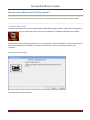
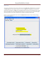
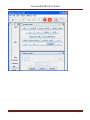
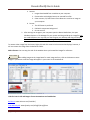
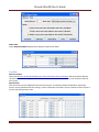
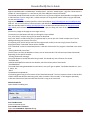
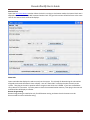
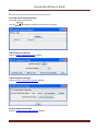
or totally new Install. Once you have downloaded the JMRI software and installed it, simply open the program in the usual manner for your operating system. An icon for DecoderPro3® should be installed on your Desktop. DecoderPro3® may be opened by double click on the Desktop icon and the DecoderPro3® initial screen as shown below will be displayed on completion of startup for a brand new install with no settings stored in your computer.. First time install start screen Press Next button starts the wizard.. [Typetext]
Page5
DecoderPro3®User’sGuide
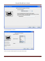
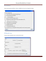
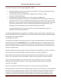
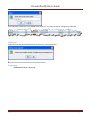
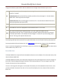
Press the Next button to continue Select your system and other options for your system will be shown. [Typetext]
Page6
DecoderPro3®User’sGuide
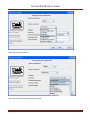
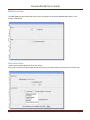
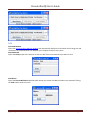
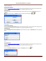
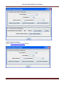
Select your system connection. Select your Serial port and Command station type. [Typetext]
Page7
DecoderPro3®User’sGuide
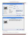
Next Connection Prefix and Connection Name, at this time leave as default. Press the Next button Press the Finish button DecoderPro3® main window is displayed with instructions for Getting Started [Typetext]
Page8
DecoderPro3®User’sGuide
You may want to set up the other preferences at this time, if so go to Preferences screen will come up that allows you to set up the system for your particular configuration. Previoususer
IfyouareupdatingandDecoderPro®hasbeeninstalledpreviously,thenproceedhere:
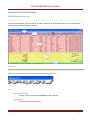
Once you have downloaded the JMRI software and installed it, simply open the program in the usual manner for your operating system. An icon for DecoderPro3® should be installed on your Desktop. DecoderPro3® may be opened by double click on the Desktop icon and the DecoderPro3® initial screen as shown below will be displayed on completion of startup with no roster entries. [Typetext]
Page9
DecoderPro3®User’sGuide
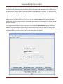
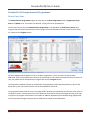
DecoderPro3 will open showing your roster entries if you already have established a roster of locomotives. It may take a while for this screen to come up, especially on older and slower computers. Remember that you are essentially running the program on a Java emulator over your native operating system software. New computers can do this fairly quickly, but older ones will feel like they're taking forever. Be patient ‐ it will come up eventually! Even on older computers, once the program is up the response time is quite good. If this is the first time you have run the program after you installed the software, the Preferences screen will come up automatically to allow you to set up the system for your particular configuration. Also if you change your system configuration, or if you have your laptop away from the railroad, but you want to play with JMRI there is a simulator mode you may want to try. So click next, and we’ll have a look at preferences. DecoderPro3 may be opened from DecoderPro Roster Menu [Typetext]
Page10
DecoderPro3®User’sGuide
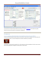
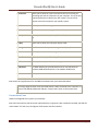
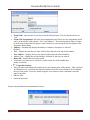
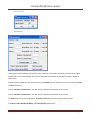
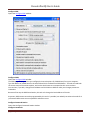
HowdoIsetupmypreferences?
From the Edit menu in DecoderPro3 select Preferences option: (This window may open automatically the first time you run the program.) [Typetext]
Page11
DecoderPro3®User’sGuide
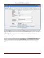
As a first time user the most important information is the Connections screen where you describe how the computer will talk to the command station. Most of rest you can leave at the initial or “default” settings until you find a need to change things to suit your fancy. Most importantly, you must click the Save button to finalize your settings and then re‐start the program to have them take effect. The Preferences window provides access to the basic configuration information to connect your computer to your DCC system. You will be using that system to actually program and operate trains equipped with DCC decoders. An important concept to keep in mind is that JMRI is nothing more than a very smart throttle. If you can do something with your throttle you can probably do it faster and easier with JMRI. However, if your system can’t do what you want, either because your system is not connected properly (it’s broken) or the system manufacturer did not incorporate that capability, then JMRI will not be able to do it either. In the latter case JMRI will probably give you an error message or have the command “greyed out” to help you identify why it can’t accomplish your request. The window is split into two panes, on the left side is a list of preference groups that may be set. Clicking on one of the items opens the options that may be set in the right side pane. No selection have been made [Typetext]
Page12
DecoderPro3®User’sGuide
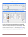
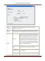
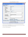
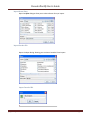
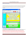
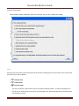
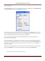
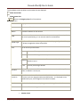
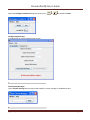
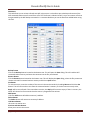
Connections Allows you to select the system connection that you are using for controlling DCC and the connection to your computer. This is the only required preferences to define your DCC system. The rest of the features are used to customize your specific system. Defaults Shows system default settings File Locations Set default location for saving User files and Script Files Start Up Allows you to set Actions, Buttons, Files and Scripts that run at Start Up Display Allows you to select your computer display mode Messages Set default actions for system message when displayed Roster Allows you to set your default Programmer and roster location Throttle Allows you to set up you Throttle preferences Wi Throttle Allows you to set up a Wi Throttle settings JSON Server The JMRI JSON Servlet provides web access to lists and values for numerous JMRI‐defined entities, in the modern JSON format. Web Server Sets up the Decoder Pro® miniServer Now we will set up preferences for the JMRI environment with your command station. I am using a Digitrax Super Chief Command Station (radio) interfaced to the computer via loconet, PR3 (MS100 mode) and USB port. I keep master roster on the System Drive. ConnectionsPane
(TABS are configured to the system your selected) Now select Connections and connection options display in right pane. After saved and restarted, the TAB will read LocoNet. This the set up for Digitrax Chief System with PR3 interface. [Typetext]
Page13
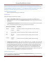
DecoderPro3®User’sGuide
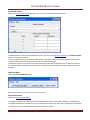
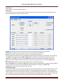
System manufacturer: Drop‐down list with all the supported DCC manufacturers, select the manufacturer of your system. System connection: Drop‐down list with all of the supported DCC system interfaces supported by the manufacturer that you selected, select the interface that you are using. Serial Port: Settings: Drop‐down list to select the serial port to which your DCC interface is connected. If you do not know, check your system hardware configuration manual. A second drop‐
down list may include a selection if there are more than one possibility. Possibility Drop‐down list to select the serial port to which your DCC interface is connected. If you do not know, check your system hardware configuration manual. A second drop‐down list may include a selection if there are more than one possibility Command station Drop‐down list to select the command station type that type: JMRI will be using to send your DCC commands. Connection prefix Include the prefix for your connection, in the case shown the "L" is default Connection name Should default to the connection used [Typetext]
Page14
DecoderPro3®User’sGuide
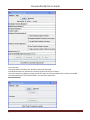
Additional Connection Settings, if checked: Disable Connection
This option will disable all the connection settings. DefaultsPane
Shows the default settings which will depend upon the system used. [Typetext]
Page15
DecoderPro3®User’sGuide
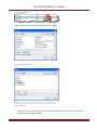
FilelocationsPane
User File Locations Select the location for your user files on your system Jython Script Set the location of Jython Script files Location [Typetext]
Page16
DecoderPro3®User’sGuide
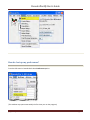
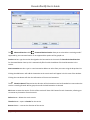
StartUpPane
Add Action
Actions to set up a TAB Startup action Add Button
Buttons to the TAB toolbar of DecoderPro3 [Typetext]
Page17
DecoderPro3®User’sGuide
Add Files
Files TAB that you want to load at startup Add Scripts
Scripts to load at TAB startup You may add as many items as you want to open on start up. Example of Actions Remove
Removes the item from the Start Up sequence. All of the panes are of the same format. [Typetext]
Page18
DecoderPro3®User’sGuide
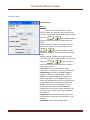
DisplayPanes
GUITAB
Metal Windows Classic elect your preferred appearance for buttons, menus, etc. CDEMotif Windows Nimbus Select font size in points select font size Use non‐standard release event for mouse click? [Typetext]
Page19
DecoderPro3®User’sGuide
LocaleTAB
Drop‐down list to select your location and language ConsoleTAB
Display settings for the JMRI system console. [Typetext]
Page20
DecoderPro3®User’sGuide
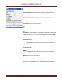
MessagesPanes
TABS and selections can be used to set how and when messages are displayed. RosterPanes
ProgrammerTAB
This pane is used to set the preferred decoder programmer. RosterTAB
You may set the default location of the locomotive roster and the default owner’s name. [Typetext]
Page21
DecoderPro3®User’sGuide
ThrottlePane
Select throttle startup conditions, shown are defaults, but you may change the settings. WiThrottlePane
This pane allows WiThottle users to customize the setup. [Typetext]
Page22
DecoderPro3®User’sGuide
JSONServerPane
The JMRI JSON Servlet provides web access to lists and values for numerous JMRI‐defined entities, in the modern JSON format. WebServerPane
Use this pane to setup MiniServer if you are using it. Ajax is now in use for smoother image refresh and clicking. For older browser you may want to unselect Ajax. [Typetext]
Page23
DecoderPro3®User’sGuide
Before you exit the preferences, click on Save
button to save all your selections. YoumustrestartDecoderProforpreferencestotakeeffect
[Typetext]
Page24
DecoderPro3®User’sGuide
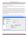
HowdoIsetuptoprogramadecoder?
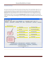
Prior to using the programmer you need to have completed the previous section (Getting Started), have your computer connected to your command station/booster with the required interface device for your DCC system, you are now ready to actually program a decoder that has been installed in your locomotive. On your initial opening DecoderPro3, the main page will be displayed: (After preferences are set) The list of locomotives programmed by DecoderPro3 will be blank until you add a locomotive. From then on when it is opened a list of all the locomotives whose decoders you have previously programmed in DecoderPro3 or classic DecoderPro will be listed. DecoderPro3 provides access to the JMRI tools required to program DCC decoders. If you are an advanced user, using PanelPro to run your layout, then you may start PanelPro and then from the File menu start DecoderPro3. If you already have roster entries and you want to start programming in Comprehensive Programmer, double‐
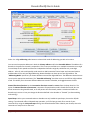
click on the roster entry. DecoderPro3 by its self may program DCC decoders and also use the other JMRI tools to manually operte your trains from the computer interface. These include throttle control and power control of your layout if your DCC system allows them.. The DecoderPro3 window is divided into five main section from top to bottom. 1. The Menu Bar. 2. The Tool Bar 3. The Roster Table a list of all the decoders in your roster that are part of the active roster group. To set‐up a roster group in addition to the default group of All Entries see Settings for Roster groups.. 4. The Decoder Information Area. Show information about any selected locomotive in the roster list. 5. A status bar that reports information about DecoderPro3 operation including errors. [Typetext]
Page25
DecoderPro3®User’sGuide
Anywhere in the roster table you may right‐click and a context menu will be displayed. Context Menu (Right click) Program Programmer type The link ed image cannot be display ed. The file
may hav e been mov ed, renamed, or deleted.
Verify that the link points to the correct file and
location.
Programming Track Programming on Main Edit (Allows you to edit roster without making changes to program) Labels and Media Opens programming page to select either Labels TAB or Roster Media TAB
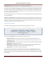
Throttle Opens a JMRI Throttle Duplicate Duplicates the selected roster entry to use for same type of locomotive. Delete Deletes roster entry. At this time a new user will have no entries in the Roster list of locomotives. If you are updating program and have a Roster installed the Roster list will be populated as shown. We can now add a locomotive to the list. [Typetext]
Page26
DecoderPro3®User’sGuide
AddingNewLocomotive
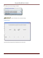
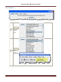
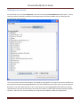
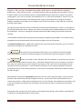
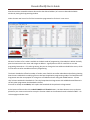
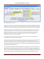
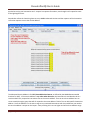
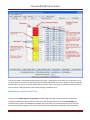
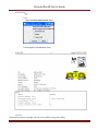
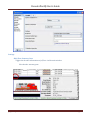
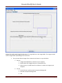
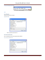
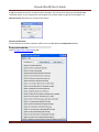
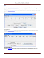
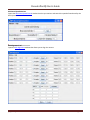
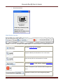
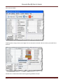
On the Tool Bar is an icon labeled New Loco, click on the icon and the Create New Loco window opens. Place a locomotive (with the decoder installed) on the Programming Track (Service Mode), click on Read type from decoder button (mid right side) The screen below several possible decoders will probably be highlighted. This happens because the decoders are electrically the same but are packaged differently to fit the locomotives that they are used in. If you know which decoder is in use, then select that one. If not, in most cases any of the highlighted decoders will work, and you should select the one with the least letters at the end, since letters are often used to denote locomotive specific variations. Note all of the Tsunami decoders are using the same hardware in different configurations. [Typetext]
Page27
DecoderPro3®User’sGuide
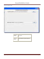
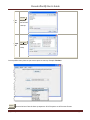
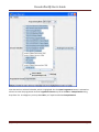
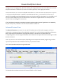
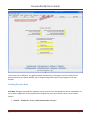
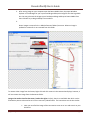
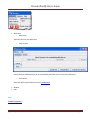
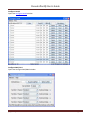
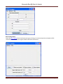
Note that we have selected a decoder, which is highlighted. Also the Open Programmer button is activated to allow us to enter the programmer and the Programmer format may be set to Basic or Comprehensive using drop down list.. As a beginner you may select Basic, or if experienced select Comprehensive. [Typetext]
Page28
DecoderPro3®User’sGuide
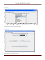
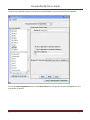
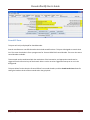
I know that this decoder is Athern FP‐45 factory installed decoder in nscale. So I will select that decoder. Click on the Open Programmer button and the Roster Entry Pane will open for the Selected Programmer. The programmer is opened. [Typetext]
Page29
DecoderPro3®User’sGuide
TheBasicProgrammer
TheRosterEntryPane
The Basic Programmer uses only the required screens to set up the decoder for DCC operation and
creating a Roster entry and uses only the first two TABs. The first action in programming a locomotive
with DecoderPro3® is to fill out the roster entry screen.
A roster is a database of all locomotives that your installation of DecoderPro3® has programmed. All of
this information will be contained in the list on the DecoderPro3 main page. It includes the information
seen in the screen below:
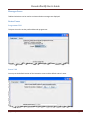
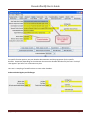
Most of these fields are self‐explanatory. However, note that the first field (ID) becomes the file name in the Roster for the locomotive you are programming. Set up a schema to identify your locomotive to its decoder [Typetext]
Page30
DecoderPro3®User’sGuide
program. I.e. Mfr, Loco Type, and Address (Kato_SD40‐2_5645). Spaces in the ID field will be changed to underscores (_) when the file is written. In a club environment, often the ID begins with the owner’s name, or member number. This way the Roster (which is sorted alphabetically) will keep all of an owner's locomotives listed together. This is not as necessary with DecoderPro3 as it is in the classic DecoderPro®, because it is now possible to sort the information on the opening screen using any of the columns by clicking on the column heading. DecoderPro3 also allows you to categorize roster entries into Groups, so you could have a separate group for each member. We’ll get to Groups and all the other neat stuff that can be done with DecoderPro3 in a while. I just thought I’d give you peek behind the curtain, and give you a chance to mentally thank the JMRI developers for all their work on DecoderPro3. Of course a message to that effect posted to the JMRI Yahoo group would also be warmly received. The DCC address will be filled in automatically when we get to programming the address. The Decoder Family and Model are entered automatically from the Selection page we just used to get here. The Decoder Comment field is a good place to add the date you purchased the locomotive, price, or any other information you might feel is important to record. Save to Roster
The button stores the current decoder information to your computer hard drive and folder where your roster file is located. The default storage is the same directory where the program is installed. Reset to Defaults
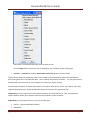
button can be used to return the Roster file to the condition of a new file for the type and The version of the decoder listed in the roster entry. It does NOT change the values in the roster file on your hard disk, unless you specifically save it after using this reset button. It also is not written to the decoder until you specifically select a write operation. It was included in DecoderPro so that if you get hopelessly confused in proceeding screen to screen entering variables, you can return to the decoder manufacturers baseline default set and start again. Most decoders will activate the Reset Menu (next to the File menu at the top of the page). This will reset the decoder to the manufacturers default settings for all the CVs, or just some of them if the manufacturer has several reset routines. It does this by writing directly to a CV in the decoder, if the decoder has that feature, CV8 in the case of Digitrax. All decoders may not support reset and how they work is manufacturer and decoder dependent. One decoder with a lengthy list of reset routines is the QSI Revolution decoder, which enables a drop‐down list of options for resetting the decoder as shown below: [Typetext]
Page31
DecoderPro3®User’sGuide
You will note that the decoder address is shown but grayed out (or blank if this is a new locomotive in the roster). This field is automatically filled in by the program and is determined from the address entered using the Basic tab which we will get to shortly. This address is used with the Ident function on the start page if you wish to recall a locomotive that is already in your roster. The Programming mode can be changed by clicking on the drop down box [Typetext]
Page32
DecoderPro3®User’sGuide
There are options for several programming modes. JMRI now selects the best mode for you. It determines this from the command station type you are using and the decoder model you are attempting to program. Usually this will be OK. If you find that you are having a problem with programming you may try a different mode. For most newer decoders, stay with Paged mode or whichever Direct mode your Command Station supports. Your decoder documentation should let you know if programming in some other mode is necessary... but if you are having problems, experiment. If a mode is not supported for the selected decoder and system, that option will be grayed out. For this decoder I will use Direct Bye Mode. When you make your selection, the programming mode should now display to the left of the in the dropdown box. ProgrammingModes
Some brief comments on Programming Modes [Typetext]
Page33
DecoderPro3®User’sGuide
AddressMode is an outdated programming method that is included here for the sake of full compliance with the NMRA DCC standard. RegisterMode is an expanded form of Address Mode, and is still used by some older and/or lower end decoders, particularly some from MRC and Wangrow. It is inherently limited in its ability to access all CVs in a decoder. PagedModeis an expansion of Register mode that gives full access to all decoder CVs. DirectMode is another method, not yet supported by all decoders, that allows full access. There are two ways of implementing Direct Mode. The radio button(s) for the Direct Mode method(s) your command station supports will be activated. If you experience difficulty programming a decoder in Paged Mode, try Direct Mode, then Register Mode, and finally Address Mode. The EasyDCC AD4 Accessory Decoder can only be programmed in Direct Mode. Below is a Basic Programming Roster setup for Athearn FP‐45 locomotive in n scale with OEM decoder (Tsunami 750) decoder. Note in the status at the bottom of pane indicates that the file has been saved. [Typetext]
Page34
DecoderPro3®User’sGuide
Now that we have the Roster information all in order, we can continue with programming the decoder. Now it's time to click on the Save to Roster button to save this data. Note that there will be brief message in status bar at the bottom of the screen that roster has been saved. Let’s move on to the Basic Programmer. [Typetext]
Page35
DecoderPro3®User’sGuide
BasicPane
You may have noticed that at the top of the window are two tabs: Roster Entry and Basic. We have completed the Roster Entry pane of the Program window, now, click on the Basic tab to change panes to continue with programming your decoder. The Basic pane will be displayed and look similar to the following illustration: Many panes in the programmer contain decoder dependent features, as a result what you see may not exactly agree with what you see here. Only those variables that your decoder can implement will be shown. Below is a screen for OEM decoder that is used in the Athearn FP‐45 locomotive. Shown in factory settings, which is normally address 3 . [Typetext]
Page36
DecoderPro3®User’sGuide
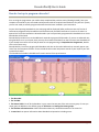
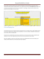
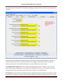
You will see three options you can change, highlighted in yellow: 1. The decoder address (should be unique among your locomotives, unless you are operating sevral as a set) often the locomotive number is used. 2. Two radio buttons that let you toggle between 2 digit (one byte, "Normal") or 4 digit (two byte, "Extended") addressing 3. Analog operation (enables the decoder to run under regular DC voltage/analog control) Enable Analog Operation with caution, as some decoders will jump to full speed resulting in a “Runaway locomotive” if they are enabled for Analog Operation and encounter power spikes on a DCC digital signal. They seem to get confused, and revert to Analog operation and use the full track voltage DCC power to take off and GO! There is no stopping them without removing layout power. Very disturbing to your operating mates, but better than running into them at full tilt. To enable Analog (old style DC, some vendors refer to this as dual mode) Operation select the appropriate entry from the drop‐down list. The yellow highlighting indicates these options are "probable" settings and have not been confirmed from the decoder. Settings that have been changed by the user and have not been written back to the decoder appear in a orange color. You will see examples of this throughout the manual. To read the actual settings for these options (and IF your system and installed decoder will allow read back of decoder values), click on the Read full sheet button. The individual settings will turn red while they are in the process of being read (clever, eh?), and will turn white once the values have been read successfully from the decoder. Once again, Decoder Pro must play "Twenty Questions" to get this information, and sometimes even has to ask a couple of times. Be patient, especially with older computers. At the very bottom of the pane (where it says "idle") you will see a running account of exactly what DecoderPro is doing, for example, the specific CV being read. Again, the Read full sheet button and Read all sheets buttons functions are dependent on your command station. If your system does not have the capability to read CVs, then these buttons will not be available. If you wish to change the address of the locomotive, type in the new address. To turn on or off 4 digit addressing, select the desired radio button. . Be sure that the address type agrees with the number of characters in the address. When you are finished, click on Write full sheet button to write the new values in the decoder. Writing usually takes much less time than reading, because the value can be sent directly. As the write operation proceeds, the data will change from yellow to white. If there is difficulty writing to the decoder, the data will change to red. The software will automatically keep trying until the write operation is successful. In some instances the system will “time‐out” after a certain number of tries without an acknowledgement from the [Typetext]
Page37
DecoderPro3®User’sGuide
decoder. This does not necessarily mean that the values have not been written, just that the program has not received an acknowledgement. This can be due to the locomotive moving and getting on dirty track so that it can’t pulse back or possibly because the command station or decoder cannot read back. Try moving the loco and try again. If it is a command station or decoder read‐back issue, try the loco on the mainline and see if the programming was successful. To finish this "basic" programming of a decoder, click once more on the Roster Entry tab, You will see that the address field has now been filled in, so you can now click on the Save to roster button. Your new decoder settings have now been written not only to the decoder, but also saved to a computer file where they may be recalled in the future. I have programmed the address for this locomotive and clicked on the Write full sheet button to send the address to the command station to program the decoder. Note that the status line keeps you updated as to what is writing and should finish with OK, which is good or an error message which usually means the write was not completed. All the entries are now in white color as they match the decoder. [Typetext]
Page38
DecoderPro3®User’sGuide
Now that we have entered the Roster data and set the desired address, let’s return to DecoderPro3 Main window by closing the Programming window. Notice that we now have a list of all the locomotives programmed so far that is in our roster. What we’ve done so far is what is available in the Basic mode of programming in DecoderPro3. Which i basically puts the Locomotive in the roster and assigns an address. A good place to start for new folks or at a club programing locomotives. It’s hard to go wrong, but you can change the loco address and add it the roster, which are the two most often needed actions with programming. The classic DecoderPro offered a number of modes, most of which were often redundant and confusing showing how the user could edit the underlying file to make special application programming modes. The Comprehensive Programmer was the most popular for a long time until Advanced came along with added features. So now they’ve been combined in DecoderPro3. Thus the Comprehensive Programmer with added advanced features is the only other programmer that DecoderPro3 offers. Since we’ve already covered Basic, let's explore the DecoderPro3 Comprehensive Programmer! At the bottom of the window is the Labels & Media and Throttle buttons. Use these buttons to set up the Icon photos for your roster entries and to set‐up the Function Labels on the software throttle included in JMRI®. Go to those pages and take a look. [Typetext]
Page39
DecoderPro3®User’sGuide
DecoderPro3®ComprehensiveProgrammer
RosterEntryPane
The Comprehensive Programmer begins the same way as the Basic Programmer, with a Programmer Setup Pane and a Roster Pane. The content are identical, so they will not be repeated here. Just be sure that you select the Comprehensive Programmer in the DecoderPro3 Preferences, Roster pane, Program TAB, then select locomotive you wish to program from the DecoderPro3 main screen from the roster list, now press the Program button. We have programmed the Athearn FP‐45 in the Basic Programmer, it is on the roster list and has been addressed. If we want to add the extra features of the decoder, we will select the locomotive from the roster list then, set preferences for Comprehensive Program then click the Program button. The Programmer window will open as shown below. All programmers, Basic and Comprehensive, open to the Roster Entry pane, which will be similar to that shown below for the FP‐45. The programmer opens with the roster entry page filled in because we selected the loco from the roster panel in the previous screen.. Note that there are now a whole lot more TABs at the top of the page, allowing us to open many panes to program more features. The number of TABS will depend upon the decoder being programmed. This Tsunami Sound Programming has several TABS that are unique to sound decoders. [Typetext]
Page40
DecoderPro3®User’sGuide
Note that the Roster pane is essentially unchanged from the Basic programmer, but the window has a LOT more options in the Tabs at the top. If you are unsure how to handle the Roster information, go back to that section in the Basic Programmer. If you're ready to move on to bigger and better things, let's go to the next tab. ExpandedBasicPane
One of the first things you will notice about the expanded Basic Pane in the Comprehensive Programmer is that there are a lot more options than you found in the Basic Programmer. Now use the Read full sheet button to read the values that the locomotive is programmed to. Now you can determine if you want to change any values. [Typetext]
Page41
DecoderPro3®User’sGuide
Select 2 or 4 digit addressing radio button to select which mode of addressing you wish to be active You can enter locomotive addresses in both the Primary address and/or the Extended address. The address of a decoder is the prefix for the code it responds to. This is how you are able to run multiple locomotives on a single line and keep all their speeds and functions independent. Decoders originally could have only a two digit address... after all, who could possibly need more than 100 locomotives? Some lower‐end command stations and decoders still use only two digit addressing. Newer decoders can have up to a four digit address. The "Addressing Mode" option lets you choose between two and four digit addresses. The addresses themselves are input into the appropriate text boxes. The "Extended Addressing" check box turns on and off the 4 digit address mode. This allows you to have two different addresses stored in a decoder, and toggle between the two. Normal direction of motion: Set the Locomotive direction: normal or reverse from the drop‐down list. The option for Normal direction of movement is important for people who model railroads like the NS, who ran diesel locomotives long hood forward, or for the person who occasionally makes a mistake and hooks the decoder up in reverse. It lets you change the direction defined in the decoder as "forward" (no disassembling and rewiring). Speed Steps: Unless your command station or decoder can only handle 14 speed steps, choose the 28/128 setting. If your decoder offers 128 speed step operation, you'll find you get much finer control of your locomotives by using the 128 speed steps setting. You choose between 128 or 28 with your throttle, when the locomotive is ready to roll on the track. [Typetext]
Page42
DecoderPro3®User’sGuide
Analog operation (enables the decoder to run under regular DC voltage/analog control) Enable Analog Operation with caution, as some decoders will jump to full speed resulting in a “Runaway locomotive” if they are enabled for Analog Operation and encounter power spikes on a DCC digital signal. They seem to get confused, and revert to Analog operation and use the full track voltage DCC power to take off and GO! There is no stopping them without removing layout power. Very disturbing to your operating mates, but better than running into them at full tilt. To enable Analog (old style DC, some vendors refer to this as dual mode) Operation select the appropriate entry from the drop‐down list. User ID #1" and User ID #2 (off to the right} there are two CVs that have nothing to do with any function of the decoder. They simply provide you with a method of electronically marking your equipment. Use these CVs, even though you may have custom‐painted equipment for your own free‐lanced railroad ‐ it provides one more way to identify your decoders if they are removed from the loco. TheReadandWriteButtons
At the bottom of all the programmer panes you will find three rows of buttons, as shown : The top row operates ONLY on the currently visible pane. These buttons are: 1. Read changes on sheet ‐ an "Oops!" button that lets you recover data from the decoder if you've changed it accidentally on the computer (and don't remember what the values were!), but only if you haven’t written it yet. 2. Write changes on sheet ‐ faster than writing all the data on the sheet, and ideal for tweaking changes in Ops mode, programming on the main track. 3. Read full sheet ‐ read all data in this pane from the decoder. Note this may take a great deal of time, depending upon the speed of your computer and the controller station in use. 4. Write full sheet ‐ writes all data in this pane to the decoder. The second row of buttons performs essentially the same functions, but on the entire range of CVs for the decoder. This allows you to read all CVs, for example, or to make a series of changes across several panes, and when done then write them all to the decoder. Again, you have the option of reading/writing only the changed data, or all data. [Typetext]
Page43
DecoderPro3®User’sGuide
Below the two rows of buttons is a text line that shows what the current programming mode setting, and a Set... button that allows you to change it without exiting the programmer. Go to Programming Modes for further information. Finally, the bottom line of the pane is a status bar that tells you exactly what the system is doing. It shows idle in these screen shots because the system was not actively programming decoders when they were made. Now let’s go to the Motor TAB. MotorControlPane
Motor control is divided into three separate panes. The Motor Control pane deals with CV’s for simulating locomotive weight or inertia. The Basic Speed Control pane deals with basic motor control CV’s and the third Speed Table pane covers those dealing with the Speed Table method of controlling the motor. These last two methods of motor control are mutually exclusive. The selection is made with a radio button at the top of each of those two panes. The default selection is Basic Speed Control. [Typetext]
Page44
DecoderPro3®User’sGuide
TheMotorPane
The contents of the Motor pane will vary significantly between different brands and models of decoders. In the case of the decoder shown in the illustration: Acceleration Rate and Deceleration Rate help simulate a locomotive under load ‐ but don't use them unless you have very clean track, because an interruption of power can make a locomotive stop and cycle through the acceleration curve again! On the latest Tsunami Diesel sound decoders the firmware has been changed. The decoder now returns to the last speed setting before the power interruption but it has no knowledge of where it was in the acceleration curve. So if you have been in the habit of using lots of momentum and setting speed to maximum to get the sound of a notch 8 motor, be aware that if the loco loses power for just an instant from a dirt spot on the rails, it will resume at the top speed step and appear to be running away. High deceleration rates can make station stops and switching realistic, but very challenging! Back EMF or Speed stabilization is implemented differently by each manufacturer.. See your decoder documentation for the best ways to implement these variables, and be prepared to do a lot of experimenting! However they do it and whatever they call it, you should find it in this pane. [Typetext]
Page45
DecoderPro3®User’sGuide
SpeedControlPane
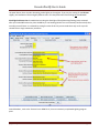
The Speed Control pane looks very complicated, but it can be one of the most significant in improving the performance of your locomotive fleet. Remember if you use Speed Table TAB this TAB is not used. Let's look first at the top of the pane: You now have the option of using Basic Speed Control (this pane) or Speed Table to control your locomotive's speed. Use the tabs at the top of the screen to select the method you wish to use and then click the button in the top center for the page to select that method of speed control. Whichever one you select last with the button will be the method used for speed control. Now back to Basic Speed Control Pane. We see the Start Voltage (0‐255) slider to set the start voltage. What appears in the body of this panel is dependent on what is available from your decoder manufacturer. Most have something similar to what is shown, but the Soundtraxx Tsunami series is very limited. We’ll show you a way around this limitation when we get to the Speed Table screen. Three important CVs are programmed in this pane Vstart, Vmid and Vhigh. They work together to make a very basic three point speed table. On some decoders these settings may be labeled differently and all three may not be available. Decoder Pro will show the correct options for your selected decoder. Possible setting that can appear on this TAB. Vstart (Start Voltage) is the voltage at the first speed step. If your locomotive didn't start moving until there were three volts on the track with analog power, this lets you set up the decoder to give it 2.99 volts right away, so it will start moving when you advance your DCC throttle. [Typetext]
Page46
DecoderPro3®User’sGuide
Vhigh ( Top Voltage, Max Voltage, Maximum Voltage) is the maximum amount of power the locomotive will get from the decoder. If your locomotive looks like Chuck Yeager's X‐1 at full throttle, then you can trim the top speed down to a more reasonable scale level. A similar looking limit can be set on the Roster Entry screen, but it only apples to JMRI Throttles. Vmid (Mid Voltage, Midpoint Voltage) lets you configure the slope between Vstart and Vhigh a bit, so that if your locomotive reaches full speed at 5 volts, you can stretch out the lower end of the curve to get more fine control in a useful speed range. If you are having problems with unpredictable speeds with your locomotives, check these settings. Sometimes, one or more of these settings have been changed accidentally (usually due to an error in programming CV’s with a throttle), leading to very odd speed performance. In particular, if the Vmid is lower than Vstart or higher than Vhigh, results can be highly unpredictable. Decoder Pro will not let you make this mistake. Forward Trim and Reverse Trim allow you to compensate for differences in the forward speed and reverse speed of the locomotive. Most model locomotives do not run at exactly the same speed forward and backward due to the motor mechanics and the gear train to the wheels. The settings for these controls are not as intuitive as you might think. A setting of 0 in these CVs turns them off. However, a setting of 128 in either of them will have no visible effect! To make the forward and reverse trim effective, raise the value above 128 to increase speed, and lower it below 128 to decrease speed in this pane. The Forward and Reverse Trim does not work the same for all decoders, with variations between manufacturers. Usethesesuggestionsforusingthebasicmotorcontrolsandprogrammingthemonthemain.
Unless you want to get into some precision speed matching, you probably won't need to use the Speed Tables you'll see on the Speed Table pane‐ you'll be able to accomplish much of what you want using just Kick start, and Start Volts, Mid Volts, and Max Volts if they are available in this pane... but how to do this? Start with the Kick start value, and Programming on the main rather than the programming track. Set the locomotive to be programmed on throttle step 1. If it moves at all, don’t changes the Kick start value. If it doesn't move, slowly step up the throttle until it does. Then, turn the throttle down. If the locomotive stops at the same setting it started, you won't need to set the Kick start value. However, if it continues to run at a slower speed than it would start, then increase the Kick start value until it will start and run at its slowest possible speed. Now, if the locomotive isn't running at throttle step 1, increase the Start Volts value (and write it) without changing the throttle until the locomotive barely crawls... you can usually get this down to a speed of a tie a minute or so if you like! Remember, you are doing this in "ops mode", so you can make these changes while the locomotive is actually running. Don't forget to write the value changes to the decoder ‐ they won't take effect unless you do. [Typetext]
Page47
DecoderPro3®User’sGuide
Now, set the top speed of the locomotive. Run the throttle up to full, and lower the Max Volts value (and write it) until the locomotive runs at the maximum speed you want it to reach, but don't forget that adding a train will slow it down! Finally, set the Mid Volts value about half‐way between Start Volts and Max Volts. Setting it above or below the median of the Start Volts and Max Volts values will give you a crude, three point speed table. There are no hard and fast rules for the exact numbers to use. Even identical locomotives with identical decoders will need different numbers, due to variances in motors and drive trains. Experiment with the settings ‐ Decoder Pro makes it easy! Note: Not all decoders will have Start, Mid and Max Volts, but will have some version of this which will be displayed by Decoder Pro for the specific decoder. If you select Speed Table all of the settings in this pane are ignored. TheSpeedTablePane
The Speed Table allows you to fine‐tune the throttle response of your locomotive. You might opt to match all of your locomotives so they run at the same speed for the same throttle setting, or you might want to set the table up so that your locomotive runs at the actual scale speed indicated by the throttle. Or maybe you have someone in your operating group that likes to switch the yard at Mach 2.5, and you want to slow them down a bit. There are a lot of ways to use this feature. (This feature may vary by manufacturer and decoder series) Some decoders may only have preset curves that you can select. You now have the option of using Speed Table (this pane) which if selected and written to the decoder will replace the Basic Speed Control to set your locomotive's speed control mode. Whichever one you select last and write to your decoder will be the method used for speed control. To select the use of speed tables, the Use Table radio button is selected at the top of the pane, and in the case of Soundtraxx and QSI decoders, the drop down selection box must be used. See the discussion at the end of this section for an example. The default speed table for most decoders is a straight line from zero on the left to maximum on the right. The below the table duplicates that in the table.. [Typetext]
Page48
DecoderPro3®User’sGuide
StraightLineSpeedCurve
As you can see, you have both numbers and sliders to work with. Changing either a number or slider will make the other change to match it. If you are CV inquisitive, you can use the tool tip to advantage. By hovering over any of the sliders, the tool tip will reveal the CV to which you are pointing. The Match ends button will also result in a straight‐line graph, but you can offset the beginning and end by any amount you wish. The first and last steps are used to set to minimum and maximum values for the straight line. The function will then draw a straight line between those two end points. Below is an example of the result. [Typetext]
Page49
DecoderPro3®User’sGuide
Now if you’ve used DecoderPro in the past, you’re probably wondering what those little boxes at the bottom of each slider are used for. Well, they’re difficult to explain, but easy to use. They basically allow you to set a slider to control every slider in columns to its left as well as to its right. If you click two of the boxes and then move one of those sliders you’ll see that they are linked to the sliders between them. Points to the right never are higher than the slider being moved, and the points to the left are never lower that the slider being moved. This “always increasing left to right” is normally the way the sliders worked, but now the ones in between the check are linked. If the slider is lowered and then raised the straight line is drawn between the column checked to the right and the column that the slider is controlling. It’s difficult to describe, but try it and you’ll see. What could that possibly be used for, you ask? Well, many decoders (like the Soundtraxx Tsunami in this example) do not support V‐start, V‐mid and V‐max. So, if you are trying to use the simplified method of speed matching locos, these decoders won’t support it. Well now you have a way. Check the left‐hand, right‐hand and middle columns. Set the left‐hand column to V‐start, the right‐hand to V‐max and then slide the middle slider up and down until you get the V‐mid that you want. Now all you have to do is write this speed table to the loco and you’ve accomplished what you wanted to do, but the decoder manufacturer didn’t provide for. [Typetext]
Page50
DecoderPro3®User’sGuide
SubstituteforQuickSpeedMatching
If you want to set up a loco for switching you can set a start speed that is the same for the first portion of the throttle revolution and lower the top speed for use in the yard as shown below: SwitcherSpeedCurve
if you don't desire a strait‐line response curve there are other options available. The Constant ratio curve gives you a response that increases slowly in the low end and rapidly at high throttle. This function will also draw the curve between preset end points. [Typetext]
Page51
DecoderPro3®User’sGuide
ConstantRatioCurve
The Log curve reverses this response, giving you a logarithmic response curve with high acceleration at low speeds, but topping out quickly. It will also draw the curve between preset end points. LogarithmicSpeedCurve
The Shift left button moves the entire speed table to the left one space with each click on the button. The example below shows a linear 0‐255 speed table that has been shifted left three times. [Typetext]
Page52
DecoderPro3®User’sGuide
CurveShiftedLeft
The Shifted right button move the entire speed table to the right one space with each click on the button. The example below shows a linear 0‐255 speed table that has been Shifted right three times. CurveShiftedRight
Of course, you can enter the numbers individually or move the sliders one at a time to create your own fully customized speed table. To aid you with setting the individual values, the slider value is shown at the top of each slider. Also, by hovering the mouse at a slider column the number of the CV being entered will be revealed. One very important thing to remember: No matter how pretty your speed table looks, it has absolutely no effect on the locomotive unless you write it to the decoder! [Typetext]
Page53
DecoderPro3®User’sGuide
And this point is especially pertinent with the QSI and Soundtraxx Tsunami decoders, because they have a separate drop down box like the QSI box below. They require that you select the user defined speed table entry in this box or your table will not be written to the decoder. Interestingly, Tsunami puts the selection at the bottom of the list making it very easy to miss. FunctionMappingPane
Some decoders allow you to change the function assigned to each set of output wires (or pads). Multiple choices for function assignments are shown by several check boxes. This is more common in decoders with more than four functions, and in sound decoders. Some of the new sound decoders may have up to 28 functions, and your throttle may have a limited function capability. So, here’s your opportunity to pick which ones you can operate from your throttle. When this capability is present, the check boxes as shown in the window below are active and allow you to choose to which function key on the throttle each output responds. [Typetext]
Page54
DecoderPro3®User’sGuide
If a checkbox is dimmed that indicates that no changes in function assignments are possible. Not all decoders allow you to remap the functions and others have very limited functions. Only remap functions if you are sure you know what you are doing. LightingandFXFunctionsPane
This pane provides for control of some of the most "gee‐whiz" functions on the decoder. While fine‐tuning the motor is important, and speed tables help add to the realism of operation, everyone notices the lights ‐ especially when they change intensity, flicker, flash, or fade. They attract even more attention when, for example, the ditch lights that were steadily shining as the locomotive approached the crossing suddenly begin flashing alternately, then return to a steady glow; or when a locomotive pulls into a siding, stops, and dims its headlight for the approaching train. All these effects are possible with the right decoder and proper set‐up, and set‐up is what DecderPro is all about. [Typetext]
Page55
DecoderPro3®User’sGuide
Every Manufacturer and decoder family handles the lighting in a unique manner, so there are many versions of this pane. The specific effects available differ widely between manufacturers, and even between different "families" of decoders from the same maker. The above example is from a Digitrax FX decoder. Some of the advanced features you will see in many decoders (though they may go by different but similar names) The Lamp keep‐alive voltage determines how dark a light gets between "full on" moments. This can let you adjust effects to give the impression of, for example, a marker light that also has a rotary beacon in the same housing. Play with this value and see what kind of results you get for your specific decoder. FX rate adjust controls how fast an FX effect operates. The higher the number, the slower the frequency of flash or "rotation" of the effect. This can be used to set subtle differences between locomotives. As you can see from [Typetext]
Page56
DecoderPro3®User’sGuide
the panel above, there are twin alternating strobe lights on the engines. If you vary the setting for the FX Rate slightly, the locomotives flash at slightly different rates. This keeps MU units from looking too coordinated! Ditch light hold‐over time CV establishes how long the ditch light effect (alternating flashing) stays activated after you hit the F2 function key. Since the F2 key is non‐latching (think of it as a momentary contact switch) that normally turns off when it is released. By raising the value of this CV you can make them stay on for up to 30 seconds from a single momentary activation. Sound decoders , such as the Tsunami in our OEM FP‐45, have an extremely complicated Lighting program pane. [Typetext]
Page57
DecoderPro3®User’sGuide
Note that some of the lighting functions can be tied to a sound function which is unique to sound decoders. Sound decoders have many more functions than normal motor control decoders. The other lighting effects are highly variable between decoders. Check your specific decoder documentation for what the decoder is supposed to be capable of doing, and have fun playing with them. They are the most visually satisfying of all the capabilities of the decoders! Even if the function and effect are available, you may have to add the lighting to your locomotive in order to be able to use that function, such as adding ditch lights, beacons, etc. AnalogControlsPane
As discussed in the Expanded Basic Pane, some decoders allow operation on Analog or Conventional DC layouts. At the discretion of the manufacturer, some of the non‐motor responses may be changeable by setting CV’s in the decoder. This pane is where you would set these values. Typical would be whether any of the various functions (such as lights and bell) would be on or off when in DC mode. Consult your decoders manual for options available. Some decoders are Analog Controls panes are simple and others such as the FP‐45 are complicated. [Typetext]
Page58
DecoderPro3®User’sGuide
ConsistingFunctionsPane
Consisting is a means to have two or more locomotives respond to orders from the command station, and do it together in unison. There are a number of terms used to describe consisting, and the manufacturers don’t agree what those terms should be. The NMRA has adopted terminology, so that is what will be used in this discussion. Address Consisting. You merely set the address of every locomotive to be the same, and we can use the Basic Programmer pane to do this. Then a DCC instruction sent to a locomotive with address XX will cause all the locomotives with address XX to respond. It works well for locomotives that are always run together, and is portable from one layout to the other. The disadvantage is that it’s a pain to keep re‐addressing your locomotives if you don’t always run them together. So, the NMRA came up with two additional means of consisting. One is set up in, and remembered by the command station, and the other is set in the decoders. The NMRA calls the command station based system Basic Consisting. The command station keeps a list of all the locos in the consist. When an action is needed the command station sends an individual packet to every locomotive in the consist, which causes them to then act together. Since this method is command station based the consist is not portable to another system. Also, since it does not need to be programmed into the decoders, DecoderPro doesn’t need to deal with it. The NMRA calls the decoder based system Advanced Consisting. To implement this system the decoder has to have a special memory space (CV19) which is used to store a consist address. This type of consisting is portable between layouts, since the information that the loco is part of a consist, and the address information for that consist is carried in the decoder. The disadvantage is that once the locomotive is assigned to a consist it will only respond to the consist address. If you forget to “break ” the consist at the end of an operation, you will be [Typetext]
Page59
DecoderPro3®User’sGuide
puzzled as to why your locomotive won’t respond to requests for motion, even though it will respond to some of the lighting functions. DecoderPro utilizes the Consisting Pane to set up NMRA Advanced Consists and the response of the locomotive to function requests sent to the consist address. The Advanced Consist Address is for EPF (Extended Packet Format, as defined by the NMRA Recommended Practices for DCC). If the consist address is any value other than zero, the locomotive is considered to be in a consist and will only respond to instructions sent to the consist address. Thus we set a short address here to create a multiple engine group that will all respond to the same address. Think of it as an MU specific locomotive address. Since the address is in the same range as non‐consisted locomotives with short addresses, we need to be sure the address is unique on the layout. A way of doing this is to use higher end of the short address range [Typetext]
Page60
DecoderPro3®User’sGuide
starting from 127 and going down. Most folks working with single locomotives with short addresses tend to be using the manufacturer’s default of 3, or other low values, typically for their logging locomotives. This Pane also allows one to instruct the decoder what effects are to be active when the locomotive is in part of a consist, assuming the decoder is capable of responding appropriately. As an example, this allows you to specify if the headlights and other lighting functions are to be always off if the locomotive is in the middle, or tail end. This can be handy if only the “B” unit has sound. You can set it’s lights to be off in a consist, but it can sound it’s horn even though it’s in the consist. If you've had your locomotives on another layout and ran them together, but can't get them to run separately on your home system, check this to see if it's consist address has been set. AdvancedFeaturesPane
The Advanced Features pane covers CVs that don't fall readily into one of the other categories, and more importantly are not generally part of the NMRA DCC standard. This is a bit like the Netscape/Microsoft Browser Wars, areas where the manufacturer is pushing the envelope. In this case, the CV here controls the Transponding feature of newer Digitrax decoders, which allows them to report their location and engine number back to the Loconet. There may be one or several of these panes, depending on how complex the decoder programming is and the style of the person who wrote the definition file for your particular decoder. This is the Simple Advanced pane for Digitrax decoder. The Complex Advanced pane used with the Tsunami OEM of the FP‐45 decoder. [Typetext]
Page61
DecoderPro3®User’sGuide
SoundFXPane
This pane will only be displayed for Sound decoders. Several manufacturers now offer decoders that include sound functions. This pane is designed to control those CVs. The screen shot below is from a programmer for Tsunami OEM FP‐45 sound decoder. There are also steam sound decoders available. These sounds can be coordinated with the mechanism of the locomotive, and appropriate sounds can be triggered from the function keys of the throttle. Others can be set to be triggered at startup or to run in the background. This pane allows for the selection of sound effects from sound decoders, and the Sound Levels Pane allows for setting the loudness levels of those sounds when they play back. [Typetext]
Page62
DecoderPro3®User’sGuide
For specific function options, see your decoder documentation and the programmer for the specific decoder. Sometimes (depending on the volunteer that wrote the decoder definition file) there are “tool tips” that appear if you hover over a selection entry box. Here are is a sampling of sound functions on some other decoders: Athearn N Scale Big Boy and Challenger [Typetext]
Page63
DecoderPro3®User’sGuide
Digitrax F40PH [Typetext]
Page64
DecoderPro3®User’sGuide
SoundLevelsPane
Here are the controls for the relative volume levels and timing nuances of the sound decoder. Again, this is an example of one implementation. See your decoder documentation and the specific decoder programmer for details applicable to your equipment. Above all, don't be afraid to play with these settings and those in the Sound pane until you get sound you like. It's much easier to do here than it is to try to program these using a throttle! And even easier, if you are using the Ops Mode option to program the unit when it’s running on the track. If you “write changes” after doing your selection change, you’ll get instant feedback of how the sound has changed. [Typetext]
Page65
DecoderPro3®User’sGuide
GlobalCVListingPane
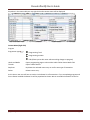
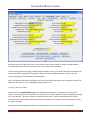
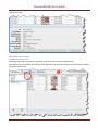
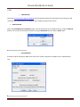
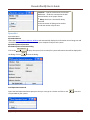
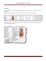
For the hard‐core programmer, this pane is a listing of the raw CV data by CV number, with data in decimal format. You may change data by typing new numbers into the Values window. State shows the validity of the data, whether it was taken From file (the decoder information saved in the Roster), Edited, Read directly from the decoder, Stored to the decoder or if the status is Unknown. Note the scroll bar on the right side of the listings. You may scroll up or down to access all of the CV listings. DecoderLocking
You tried to read a CV value and get “Error 308, No Acknowledgement from Decoder”, well the decoder may be locked. CV 15 and 16 deal with locking, if your manufacturer implements this feature (and manufacturers have slight differences as to how they implement it). If the decoder is locked, then you will not be able to read data from it or write to it. To unlock the decoder, you must enter a value into CV15 (the only CV that can be written when the decoder is locked), that is equal to the value that is currently in CV16. Now I hear you thinking “but I can’t read CV16 to know what to put into CV15”. Well, you’ll have to try all possible values, which isn’t that hard since it can only have 8 possible values 0 thru 7. After each write, try to read CV16. It’s the fastest read since it can only have 8 possible values. If JMRI responds with the no‐ack error, then try the next value. If it returns the value in CV16, you’ve unlocked the decoder and you’re in. If you have unsuccessfully tried all the 8 possibilities, then check your layout connection and the loco’s wheels for poor connections and try again. Now you say, “I’ve looked thru the list several times and CV 15 doesn’t appear”. That’s on purpose, to minimize inadvertent locking by a Write All Sheets. You will have to use the Single CV Programmer to write CV15. It can be found in the Tools menu on the Main Page, under Programmers. If you have more than one decoder in your locomotive, you probably have a decoder locking scheme implemented to be able to access each one individually for programming. You may Read or Write individual CVs using the buttons in their row. On this page, a Read sheet or Write sheet operation is the same as a Read all or Write all. Again, a reminder: you can only read CVs if your command station has that capability. [Typetext]
Page66
DecoderPro3®User’sGuide
One thing to keep in mind about the CV listing on this pane ‐ anything you can do here you can do from one of the other panes in Decoder Pro, without having to know the CV number or how to compile the values to get the desired effect. This pane is meant for advanced users of DCC used to crunching the numbers themselves. Those new to DCC can safely ignore this panel without losing any capability at all. ManufacturerSpecificDataPane
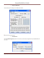
This pane in the Comprehensive Programmer provides programming for functions that are specific to an individual manufacturer, but outside the realm of the DCC standard. While items like Transponding may eventually find a place in the NMRA DCC standard, and are therefore in the advanced pane, these items are obviously beyond that category. This pane will be manufacturer dependent and decoder family dependent [Typetext]
Page67
DecoderPro3®User’sGuide
[Typetext]
Page68
DecoderPro3®User’sGuide
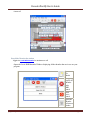
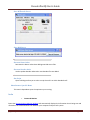
These items will, by definition, vary greatly between manufacturers. Once again, your best resource is the documentation for the specific decoder you are programming and this pane in the programmer for that decoder. PrintingDecoderData
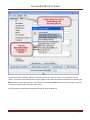
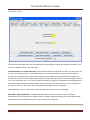
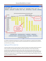
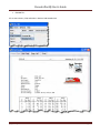
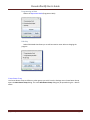
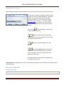
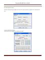
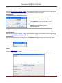
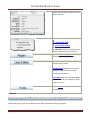
Print Data: DecoderPro provides the capability to print out a full list of the decoder CV data or selected data. To print, select the File menu of any Comprehensive Programmer Pane, then select the Print or Print Preview options.
Print all..., Preview all... Displays Select Items to Print dialog box [Typetext]
Page69
DecoderPro3®User’sGuide
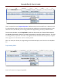
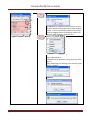
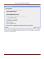
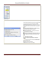
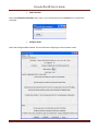
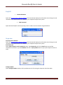
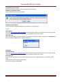
Select each or all of the decoder items that you want to print Click the OKay button to print then the Print dialog for your computer system is displayed.
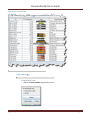
Print CVs..., Preview CVs...Displays Select Items to Print Dialog box or Preview screen These printouts show the variables by name in each category that is selected.(as shown on the DecoderPro panes) along with their CV number and Value. Use as a handy reference for the future. You may print these as PDF documents and save them on your computer for reference or future printing. Print preview will look like it’s about to print the list, and ask for which printer to use. Don’t panic!, that’s only to get the preview to work. Go ahead and select the printer and you’ll only get the preview. Import Data: You may import the list from another computer in the PR1 file format. Thus, the Export and Import capability allows you to take the data from one computer system to another. Export Data: you may export the list as one of several file types :
CSV file... (Comma separated variables) PR1DOS file... [Typetext]
Page70
DecoderPro3®User’sGuide
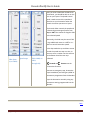
PR1WIN file... All are two columns, CV#, and Value in Decimal and Hexadecimal [Typetext]
Page71
DecoderPro3®User’sGuide
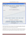
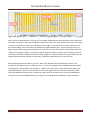
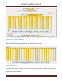
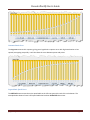
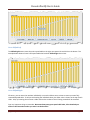
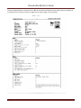
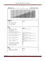
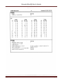
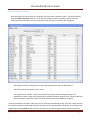
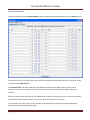
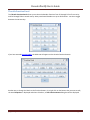
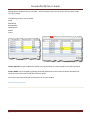
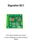
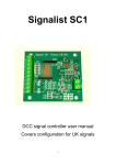
The three images below are samples of the "All" printout from the SD40‐2 that has been used as an example in many places in this manual. Click on the page to see a larger image in a new window. [Typetext]
Page72
DecoderPro3®User’sGuide
[Typetext]
Page73
DecoderPro3®User’sGuide
[Typetext]
Page74
DecoderPro3®User’sGuide
DecoderPro3®MainWindow
MainWindowOverview
When you start Decoder Pro3®, the Roster window is displayed. All of the JMRI functions can be accessed via the menu bar on the DecoderPro3® window. Menubar
Most of the DecoderPro3® functions can be accessed via the menu bar. File
NewRosterWindow
Another instance of DecoderPro3 Roster window is opened. ImportRoster
Imports Roster into DecoderPro3® [Typetext]
Page75
DecoderPro3®User’sGuide
ImportRosterEntry
Open the Open dialog to allow you to select a Roster Entry to import. ImportDecoderFile
Opens the Open dialog allowing you to select a Decoder File to import. ImportDecoderURL The link ed image cannot be display ed. The file may hav e been mov ed, renamed, or deleted. Verify that the link points to the correct file and location.
[Typetext]
Page76
DecoderPro3®User’sGuide
ExportRosterEntry
Exports .xml file for the selected locomotive on your roster. ExportCompleteRoster The link ed image cannot be display ed. The file may hav e been mov ed, renamed, or deleted. Verify that the link points to the correct file and location.
CloseWindow
Greyed out if only one Roster Window has been opened. Allows you to close an extra Roster Window that is no longer needed. [Typetext]
Page77
DecoderPro3®User’sGuide
PrintRoster
The link ed image cannot be display ed. The file
may hav e been mov ed, renamed, or deleted.
Verify that the link points to the correct file and
location.
Entry Opens the Select Items to Print dialog Printed page for selected Roster Entry. Summary
This printout may be many pages. You can print to pdf file using printer dialog. [Typetext]
Page78
DecoderPro3®User’sGuide
The link ed image cannot be display ed. The file may hav e been mov ed, renamed, or deleted. Verify that the link points to the correct file and location.
PrintPreviewRoster
The link ed image cannot be display ed. The file
may hav e been mov ed, renamed, or deleted.
Verify that the link points to the correct file and
location.
Entry
Same as print except it uses the system printers Preview window. Summary Quit
ShutsdownDecoderPro3.
Edit
Cut
Copy
Paste
DuplicateLoco Select the roster entry that you would like to duplicate. Enter a new name for the duplicate entry. [Typetext]
Page79
DecoderPro3®User’sGuide
press OK and the duplicate is now added to the roster list. You may now edit or reprogram as required. . DeleteLoco
Select the loco that you wish to delete in the roster list, select menu item. The link ed image cannot be display ed. The file may hav e been mov ed, renamed, or deleted. Verify that the link points to the correct file and location.
Preferences
Preferences window is displayed. [Typetext]
Page80
DecoderPro3®User’sGuide
Settings
Hide/ShowSummaryPane
Togglesthedecoderinformationon/off,Part4ofthemainwindow
Showdecodersummarypane
[Typetext]
Page81
DecoderPro3®User’sGuide
Hidedecodersummarypane
Note the up and down arrows in the area above the summary pane. The down arrow will hide the summary pane and the up arrow will show the summary pane when clicked on. ResetWindowSizes
notavailableyet
ResetColumnWidths
Resetsallofthecolumnstodefaultsettingsifyouhaveresizedanyofthem.
Hide/ShowRosterImages Toggles the roster image in Part 4 of the main window to show or hide ShowRosterimage. [Typetext]
Page82
DecoderPro3®User’sGuide
Hide Roster image. Hide/ShowRosterGroups
ShowRosterGroupsPane Selected group Roster Entries will be displayed. Select All Entries to show complete Roster. Note the arrows on the border of the Roster Table. Right arrow shows Roster Groups pane and Left arrow hides the Roster Groups pane. [Typetext]
Page83
DecoderPro3®User’sGuide
HideRosterGroupsPane. The link ed image cannot be display ed. The file may hav e been mov ed, renamed, or deleted. Verify that the link points to the correct file and location.
Programming The link ed image cannot be display ed. The file
may hav e been mov ed, renamed, or deleted.
Verify that the link points to the correct file and
location.
The link ed image cannot be display ed. The file may hav e been mov ed, renamed, or deleted. Verify that the link points to the correct file and location.
ProgrammingTrack
Selects the Service Mode (Programming Track ) [Typetext]
Page84
DecoderPro3®User’sGuide
ProgrammingonMain Selects the Operations Mode (Program on Main) EditOnly
Selects Edit Mode that allows you to edit locomotive roster without changing the program CreateRosterGroup
Use Create Roster Group to define any other groups you wish. From the Settings menu Create Roster Group opens the New Roster Group dialog. This same New Roster Group dialog may be opened using the + button above. [Typetext]
Page85
DecoderPro3®User’sGuide
Creates a New Roster Group
The OK button will Add the Roster Group to the list in the panel and to the drop‐down list on Main window toolbar. You can now add locomotives to the Groups either by dragging from the locomotive roster list or using the Table Associate, discussed later. Opens menu for Roster Groups Open in New Window A window may be opened for each group if you wish. Export... Opens Save dialog box allowing you to save the group to a file. Rename... Duplicate Delete [Typetext]
Page86
DecoderPro3®User’sGuide
RosterGroupTableAssociation
Once the groups are named, then you “associate” the roster entries with their group. This can be done by using the Table Association selection. At the top of the table you select the group you wish the roster entries to be associated with, then the roster entries that you want to associate with that group. Select Roster Group: from drop down list the roster group that you want to add entries to. The table shows all the engines in your roster. In the right column, Include... select the entries that you wish to add to the Roster Group, click individually to select a single item, hold the shift key down to select a range of items, hold the CNTRL key down to randomly select items. Close the Table and the entries will be added to the group. Once the associations have been made, then you can select the Active Roster Group. Once this is done then the Print and Print Summary actions will show only the roster entries associated with that group. As an example you could select the Group Santa Fe and only the roster entries in this Roster Group will be printed. The printout [Typetext]
Page87
DecoderPro3®User’sGuide
does not currently show the active group in the header. The active group will also influence any drop down box which has a list of entries in it, such as Throttle, edit entry, copy, etc. Also, when adding a new roster entry it will automatically be associated with the currently active group, so it is good practice when finishing working with a group to return the active group to Global. RestoringRostertoincludeallEngines
To return your roster to show all engines, Select Roster Group to All Entries, or Global. Then you may be certain that you are working with all engines in your roster. DisassociationofRosterEntrytoGroup
To disassociate a roster entry to a Roster Group, open Roster Group Table and uncheck roster selection and save new Group by closing the Roster Group Table. Actions
Program
Opens the Programmer that is setup in your preferences for the selected Roster Entry, Comprehensive Programmer, defaults to Basic Programmer LabelsandMedia
Opens the Labels and Media window with two tabs allowing you to set these parameters for the selected roster entry in your roster. Select the Function Labels TAB to edit your throttle function labels. Select the Roster Media TAB to edit the icon for your roster selection. [Typetext]
Page88
DecoderPro3®User’sGuide
FunctionLabelsPane
This pane is opened from the Labels & Media button the DecoderPro3 main window or from the Actions menu. This pane is more than a scratch pad to keep track of what happens when function buttons are pushed. It also interacts with the JMRI throttle. The Function Labels Tab makes settings for the Software Throttles within JMRI. Primarily the on‐screen throttles, but some of the settings are mirrored on smart‐phones (iPhone/Android) using the WiThrottle interface. When you use the roster pull‐down on the JMRI throttle to select a loco from your roster, the function buttons will be marked with the descriptions you have entered for those functions in this pane. In this example, the Function keys on the Throttle will be labeled for the FP‐45 with Tsunami OEM Sound decoder with sounds and lighting functions. [Typetext]
Page89
DecoderPro3®User’sGuide
[Typetext]
Page90
DecoderPro3®User’sGuide
Using the checkboxes, space holders and the radio button to the right of each function may be set to: Makes the function button "latching" or "non‐latching". When the box is checked the function is "locked" or "latched". lock Latched Function when pressed will stay on(down position) until pressed again i.e. Function button labeled "Bell" would ring until pressed again. Unlatched Function when pressed toggles on and then off. i.e. Function Button labeled "short horn", when pressed provides one blast of horn. off Place holder for icon that is displayed on Function Button when it is in off state. on Place holder for icon that is displayed on Function Button when it is in on state. Sets "virtual" function key for software throttle. The "lock" option also needs to be set simultaneously with the "shunt" virtual function key activation. When this Function key is pressed shunt the throttle speed slider on the software throttle changes to "center off" style for shunting, rather than the "full‐range with separate direction key" You may drag and drop icons into the off or on space holder herer or in the Throttle Function pane properties. You may also edit the function button text in the JMRI Throttle and save those changes to the selected Roster entry. To use these changed entries in the future, make sure you click on the into the Roster entry that is in use. Save to Roster
to save these values RosterMediaPane
The Roster Media Pane is opened from the DecoderPro3 button in main window or from the Action menu, then select the Roster Media TAB. The Roster Media Pane allows you to add a main image and an icon to the engines roster. The main image may be used for Throttle background image if selected in the Throttle preferences. The icon image is used in the Throttle list and various roster combo boxes. The icon is the image that will appear in the Decoder Information part of the DecoderPro3 initial screen, once you have selected a locomotive from the list. The icon will also display in the icon column of the Locomotive Roster List. [Typetext]
Page91
DecoderPro3®User’sGuide
Image to be used as main image for that roster: The large black box is the image holder. The image is placed into the image holder by following these instructions. 1. First you must find the image of the Locomotive and store it on your disk drive. a. Sources 1. Images downloaded from a website to your computer 2. Photos taken with a digital camera or scanned from film 3. Other sources, CD, DVD frames from videos etc. saved as an image to your computer b. Format 1. The GIF format is preferred with transparent background 2. PNG with transparent background 3. JPG [Typetext]
Page92
DecoderPro3®User’sGuide
2. After storing image on your computer open the Roster Media Pane, then open Windows Explorer or File Manager for your system and drag and drop the image file into the large black box. You may also save the image to your Desktop and drag and drop to Roster Media from there. DO NOT try to drag and drop from a website. 3. Roster images are stored in the <JMRI Preferences folder>/resources. When an image is updated or removed it is not removed from this folder. To remove either image from the Roster, Right click and click remove in the context that displays, however, it will not remove the image from the Resources folder. Image to be used as icon for that roster, head to the right: similarly, there is a small black box which can be filled with a picture to be used as an icon for roster entry identification. The instructions are the also similar: 1. Next you must find the image of the Locomotive to use as an icon and store it on your disk drive. [Typetext]
Page93
DecoderPro3®User’sGuide
a. Sources 1. Images downloaded from a website to your computer 2. Photos taken with a digital camera or scanned from film 3. Other sources, CD, DVD frames from videos etc. saved as an image to your computer b. Format 1. The GIF format is preferred 2. PNG with transparent background 3. Do not use JPG. 2. After storing icon image on your computer open the Roster Media Pane, the open Windows Explorer or File Manager for your system and drag and drop the image file into the small black box. You may also save the image to your Desktop and drag and drop to Roster Media from there. DO NOT try to drag and drop from a website. To remove either image from the Roster, Right click and click remove in the context that displays, however, it will not remove the image from the Resources folder. Web reference: You can copy the URL of the website where you located the images for reference Save to Roster
After adding images to the image boxes for main image and icon, click on this button to store images in your Roster. Now the image will appear in your roster list in DecoderPro3. Links for icons in GIF and images of most Locomotives are listed below: Rail Serve www.railserve.com/TrainGIFs/ Train GIF Railyard www.djcooley.com/info/gifs/loco/gifloco [Typetext]
Page94
DecoderPro3®User’sGuide
Karl's RR Pages www.kls2.com/~karl/rr/consists/ ED Bindler Train GIF.s www.bluarcher.com NewThrottle
LoadDefaultThrottleLayout
Opens the default throttle that is set in preferences [Typetext]
Page95
DecoderPro3®User’sGuide
JMRI®ThrottleWindow
The JMRI® Throttle may be used on your computer screen to replace the vendor throttle that is furnished with your DCC system. One or several throttles may be in use at one time. The Throttle opens as a floating window that may be positioned anywhere on your desktop. Note the Title Bar contains the locomotive address information. (Color shading added to show functional areas throttle panels) The Throttle Window contains Menu Bar, Toolbar and three panels which may be enabled or disabled via check box in the View menu. Each panel has a title bar with windows controls to minimize, maximize and exit: : Warning!!! Be careful with the left hand (minimize) buttons. In Windows, if the little guy is clicked it will minimize the panel, which means it is no longer visible but the restore button is lost behind the rest of the panels. The way to easily get it back, is to go into the view menu, uncheck it there, then go back again and re‐
check it. You may also drag the panels out of the way to uncover the Maximize icon for a minimized panel. [Typetext]
Page96
DecoderPro3®User’sGuide
ThrottleWindowMenuBar
File
NewThrottle...
Opens new copy of the throttle OpenThrottle
Select a saved throttle XML: file. SaveCurrentThrottle
Save a throttle file that has been opened and modified SaveCurrentThrottleAs...
[Typetext]
Page97
DecoderPro3®User’sGuide
Opens the Save dialog to allow you to save the Throttle XML file in the location you select and using the name you specify OpenThrottlesLayout...
Opens Throttle layout that you select. SaveThrottlesLayout...
Save Throttles Layout to file in Throttle Folder LoadDefaultThrottlesLayout
Load the default throttle layout from Throttle Folder SaveAsDefaultThrottlesLayout
Save as the default throttle layout from Throttle Folder StartWiThrottle
This window controls the connection between WiFi throttles, e. g. an iPhone, iPod Touch, or Android Phone and JMRI Preference in the Wi/Throttle Pane. Menu Bar [Typetext]
Page98
DecoderPro3®User’sGuide
WiThrottle o Start Server Starts the server for the WiThrottle o
Filter Controls Set up Turnouts and Routes that can be controlled by DecoderPro3® for control by WiThrottle. o
Preferences... Opens the WiThrottle Preferences Pane in preferences.
Window Help Edit
FrameProperties
[Typetext]
Page99
DecoderPro3®User’sGuide
Frame Title: Type the title of your choice for the Throttle frame. This is referred to below as
”text”.
Frame Title Components: Select the text component desired. There are two components which
can be in the title bar of the throttle “Text” and “Address” The selections allow either or both to
be in the title (in the order they appear in the selection), or one can opt for the description in the
locomotive Roster Entry
Address --Automatically display the address of whatever locomotive is selected.
(default)
Text -- Display the text that you enter in the field as the title at the top of this window
Text Address -- Display the text you entered, followed by the selected address
Address Text -- Display the selected address, followed by the text you entered
Roster ID -- Display the selected roster ID
(Note that if you enter text, it will not be visible unless one of the middle three
modes is selected)
Frame Decorations:
This will remove the individual control bars for the separate panes of the throttle. This is advised
for Windows users, as clicking the minimize buttons causes the restore button to be lost behind
the rest of the panels. Recovery entails using the view menus to remove and then restore the
panel in question.
adds the edits
aborts the operation
ExportCurrentThrottleCustomizationtoroster
[Typetext]
Page100
DecoderPro3®User’sGuide
ThrottlePreferences
Select throttle startup conditions, shown are defaults, but you may change the settings.
View
Allows you to select which of the three panels of the throttle are being shown. Place a check mark in each of the panels that your want to display.
Address Panel
Control Panel
Function Panel You may ask yourself, “Why would I want to turn off any of these panels?” As only one example, let’s say we have an observation car at the rear of a passenger train. We could equip this car with a function only decoder to control: [Typetext]
Page101
DecoderPro3®User’sGuide
1. Interior lights, 2. Rear marker lights, and 3. A rear Drum light. We have no need for the speed control pane and only need three function buttons for this “Throttle”. With a whole passenger train equipped like this, lots of screen space can be conserved by using the throttle set‐up files to optimize the Throttle windows. Then you could turn off the lights in the kitchen and lower the lights in the dining area so the passengers can enjoy the sunset as they transit the Rockies enjoying the beautiful sunset sipping Cognac…. but I digress. You get the idea. ResetFunctionButtons
Resets all the Function buttons to the default settings, , , etc. Getallcurrentthrottlecomponentsinbounds
Returns all the throttle panels to the throttle frame. SwitchThrottleframeviewmode Toggles the Throttle frames on/off Frames on. [Typetext]
Page102
DecoderPro3®User’sGuide
Frames off Show/HideThrottleslistwindow Toggles the Local JMRI throttles list window on or off Opens the Local JMRI throttles Window displaying all the throttles that are in use on your
program.
Opens a
new
Thottle
Emergency
stop for all
Throttles
under
JMRI
control
Track
power
control
Opens the
Throttles
preferences
window
[Typetext]
Page103
DecoderPro3®User’sGuide
Power(trackpowercontrol,ifsupportedbyyoursystem)
Power On Power Off Window
Minimize Lists all open DecoderPro windows. If one of the windows is clicked it will be brought to the front so that you can minimize it to the system tray. Help
Window Help... General Help... License... Locations... Context System Console Upload Debugging Info... ThrottleToolbar
The Throttle toolbar is enabled from the Throttles Preferences Pane Use Throttles preferences window to set the desired preferences. [Typetext]
Page104
DecoderPro3®User’sGuide
When it is enabled, a Throttle Window can host a set of Throttles. You can browse through these throttles: Add a new Throttle in that Throttle Window. Once the number of Throttles in a Throttle Window is greater than one, Next and Previous Icons are enabled. [Typetext]
Page105
DecoderPro3®User’sGuide
ThrottleToolbar
Open a new Throttle Window Closes the current Throttle Window Return to Previous running Locomotive. Goes to previous throttle. Goes to next throttle Goes to next running locomotive Issues an emergency stop command to all locomotives under JMRI control. Controls track power on or off, if supported. Switch to or revert from Edit Throttle mode. Opens the Local JMRI Window [Typetext]
Page106
DecoderPro3®User’sGuide
ThrottleAddressPanel
(green shading) facilitates setting the address of the locomotive you wish to control with the throttle. Primary use is to identify the decoders address, and to dispatch or release the identified address. Locomotive address may be entered by one of two methods: typed into text box or use drop‐down list to select locomotive from your roster. . If you have added Function labels, to your Roster, the label text from the Roster will be displayed on the throttle function buttons. Set
to send the address to your system Click on the to make this throttle active. Dispatch
is used to dispatch the locomotive which releases the throttle for that address so that it can be acquired by another throttle Release
is used to release the address from your system. Program
opens the Programmerfor the locomotive selected in ops‐mode (Programming on the Main) Only active when roster entry is used to select the address for the throttle. Any of the buttons may be grayed out depending on the status of your system. Control Panel (blue shading) contains the controls for applying power to the locomotive that is addressed and controlling speed ThrottleControlPanel
SpeedControlPanel
Right Click in the Speed Control Panel space and context menu with Properties is displayed. [Typetext]
Page107
DecoderPro3®User’sGuide
Click on Properties and Edit Speed Control Panel window opens. Control Panel Properties may be set by right clicking on the Throttle Control Panel(Speed), the Edit Speed Control Panel dialog is displayed. This allows you to select either of the two slider or step speed control Display Speed Slider(from 0 to 100)‐‐ displays the Throttle Control shown at the left Display Speed Steps ‐‐ displays the Throttle Control shown in the middle Display shunting speed slider(from 100 to 0 to 100) ‐‐ displays the Throttle control shown on the right Track sider in real time Switch to contiuous speed slider on function: F5
Enter the function from the Function Panel that you want to use. OK button Sets the selections Cancel button Cancels any settings [Typetext]
Page108
DecoderPro3®User’sGuide
After you have established an address for the throttle, you should be able to run the train on your layout. The Speed Control panel is used to control the speed and direction on your locomotive when the throttle is used to operate on a layout. The throttle slider controls the speed and indicates the percentage of power from Stop to 100%. Use mouse to drag the slider to the desired speed Alternately, the slider may be set to STOP in the middle and move to + 100% or to ‐
100% to control locomotive speed. Sliderfrom
0%to100%
Speedsteps
Slider100%to
100%
through0%
In the Step mode the up and down arrows control the speed one step at a time, or you may enter a number into the text box area between 0 and the max step indicated. Forward and Reverse set the locomotives direction. executes an emergency stop, locomotive stops immediately overriding any BEMF or momentum programmed into the decoder.
stops the locomotive smoothly using any momentum setting programmed into the decoder.. Back [Typetext]
Page109
DecoderPro3®User’sGuide
ThrottleFunctionPanel
The Throttle Function Panel allows you to select the decoder functions from F0 through F15 on first overlay and F16 through F28 on second overlay. Many new Sound decoders use up to 28 functions.. use the to toggle between the two overlays If you have entered Function labels, the label text will appear on the throttle Function buttons. Another way to change the labels on the function buttons, is to right click on the button that you want to edit, the word Properties. Is displayed and when clicked on, an Edit Function Button dialog box will be displayed. [Typetext]
Page110
DecoderPro3®User’sGuide
Edit Function Button allows you to edit the text displayed on the button and the function assigned. Function Number: text box to set the function assigned to the button. Warning!!! Make sure you do not assign the same function number to more than one button, otherwise, undesirable results may occur Text: the text you want displayed on the button. Font Size: Select the font size in points. Lockable ‐ locks the function when button is clicked. eg makes the button a push on / push off button. Visible ‐ makes the button visible. When unchecked the button will not show in the panel. To restore use the View menu and select Show All Function Buttons option. Function off icon: Drag and drop icon of your choice into the box. To remove icon right click and click on Remove. Function on icon: Drag and drop icon of your choice into the box. To remove icon right click and click on Remove. OK button sets all the values edited. Cancel button exits dialog without change. You can use the Save button on the Address Panel to save the edited functions to your locomotives Roster entry. [Typetext]
Page111
DecoderPro3®User’sGuide
ThedescriptionsshownaboveareonlyasmallpartofwhattheThrottleWindowcando.The
author(s)oftheThrottleWindowhavecreatedanextensivesetofHelpfilestohelpyoucustomize
ThrottleWindowstoyourwayofoperating.ToaccessHelp,justopenaNewThrottle.Then,clickon
HelpandselectWindowHelpfromthedropdownbox.There’slotsofgoodstuffinthere.
LoadsDefaultThrottleLayout
Opens the default throttle that is set in preferences ConsistingTool
Three types of consists are used on DCC systems:
A basic or primary address consist, where each locomotive is assigned the same address on the programming track, or on the main with OpsMode Programming (if supported by the command station and decoder).
A Command Station Assisted Consist (CSAC) which builds the consist using a function of your command station. Command Station Assisted Consists go by the trade names listed below.
Manufacturer Trade Name Usage Notes Digitrax Universal Consist Limited to the number of slots supported by the system. Allows any address Lenz Double Header Limited to 2 locomotives. Allows any address but 00 to be used NCE Old Style Consist Limited to 8 locomotives. Allows any address but 00 to be used EasyDCC Standard Consist Limited to 8 locomotives. Allows any address but 00 to be used A Decoder Assisted Consist (DAC), often referred to as Advanced Consist. The NMRA® has set aside CV19 as a dedicated location for consist addresses. If CV19 contains a value other than 0, the locomotive will respond to speed and direction instructions sent to the address in CV19. If CV19 contains zero then it will respond to speed and direction commands sent to the usual short or long decoder address. Since the consist address is a single CV, it is limited to the range of 1 to 127. If you add 128 to the consist address, the locomotive will run backwards (relative to it's normal direction of travel) in the consist. The DAC can be set up in the Consisting tab in the Comprehensive Programmer. DecoderProConsistingTool
The consist tool provides a visual tool for manipulating the Decoder Assisted Consists and , on some command stations, Command Station Assisted Consists. [Typetext]
Page112
DecoderPro3®User’sGuide
The Advanced Consist and the Command Station Consist allow you to select either consisting mode if supported by your command station. If not supported the options will be grayed out. Consist text box: type the consist ID assigned to the locomotives in the consist for Decoder Assisted Consists. For Command Station Consist, this is automatically filled in with the address of the lead locomotive in the consist. New Locomotive text box : type in a new locomotive address or select from you roster using the drop‐down list. Clicking the adds button will add the locomotive to the consist and it will appear in the list area of the window. Clicking the reset button will clear the information of the current locomotive. The Direction Normal ? determines the direction of the locomotive travel as forwarded or reverse when the consist is traveling forward. Will be grayed out until the lead locomotive is selected. DEL button removes the consist. The list of the consist will have a DEL button for each locomotive, allowing you to remove any locomotive from the consist. Delete button ‐‐deletes the entire consist. Throttle button ‐‐o pens a throttle for the consist. Reverse button ‐‐ reverses the direction of the consist. [Typetext]
Page113
DecoderPro3®User’sGuide
TurnoutControl
Turnout Control Turnout Enter the accessory number or tunout system name for the accessory or turnout you wish to control. For example, entering 678 and by pressing Throw n
closed
either the or , you should be able to change the state of accessory number 678 on the layout. Another example, a valid turnout system name for NCE could be NT456. Then by pressing either the Throw n
closed
or , you should be able to change the state of turnout or accessory number 456 on the layout Another example, a valid turnout name could be IT123 which is internal turnout number 123. Pressing Throw n
closed
or will only change the either the state of the internal turnout and will not change a turnout on the layout. current state: A turnout can have four states: <unknown>, <inconsistent>, <thrown> and <closed> feedback mode: some of the available feedback modes are: <DIRECT>, <ONE SENSOR>, <TWO SENSOR>, and <MONITORING>. A turnout using DIRECT mode does not have feedback from the layout. ONE SENSOR use one sensor on the layout to provide feedback on he state of the turnout. TWO SENSOR uses two sensors for feedback, one for closed and one for thrown. MONITORING gets feedback from the system by either listening to cab commands on the layout or polling the system for turnout status. Caboperation: some turnouts can be locked. If the control button is grayed out, the lock feature is not available. Pushbuttons: Shows state of Pushbuttons. [Typetext]
Page114
DecoderPro3®User’sGuide
PowerControl Speedometer
Three sensors are installed on your layout, sensor 1 and 2 for slow speeds, and sensor 1 and 3 used for higher speeds. The time to travel between the sensors is used with the distance to calculate the speed in English or Metric units Enter the sensor number for each of the sensors in the Sensor text box. You can set to start or stop on the entry or exit of the block. Enter the Distance 1 (scale feet): in text box, which is the distance between sensor 1 and 2. Enter the Distance 2 (scale feet): in text box, which is the distance between sensor 1 and 3. The Start button starts the speedometer. To metric units button converts output to metric values. The Timer 1 and 2 Speed(scale MPH): and Time (seconds) is displayed. [Typetext]
Page115
DecoderPro3®User’sGuide
SingleCVProgrammer
The Simple Programmer is opened from the Main Page of DecoderPro3® Action menu. The Simple Programmer allows you to read or write CV values in DCC decoders one at a time. Prior to reading a CV value you should enter the CV Number (address) into the CV Number text box. If writing a CV value you should enter the CV Number and then a value in the Value text box. You may enter the value as Decimal or Hexadecimal depending upon the option selected in Value is: area. On the left side of the window you can select the Programming Mode. Any mode not supported by your command station will be grayed out. If you select the Ops mode, which programs on the main track, you need to enter the address of the decoder (locomotive) that you are programming. Your DCC system may require you to check the Long address check box if the address is a long address. Most DCC systems do not allow you to read on the main, if so, the Read CV button will be disabled. Now that you have everything setup, you may read the current value in the decoder’s memory from the CV by clicking on the Read CV button or write your new value to the CV by clicking on the Write CV button. The link ed image cannot be display ed. The file may hav e been mov ed, renamed, or deleted. Verify that the link points to the correct file and location.
[Typetext]
Page116
DecoderPro3®User’sGuide
StartWiThrottleServer StartWebServer The link ed image cannot be display ed. The file may hav e been mov ed, renamed, or deleted. Verify that the link points to the correct file and location.
RecreateRosterIndex Recreates the Roster Index when adding new XML roster files. RecreateDecoderIndex Used to update Decoder Index when new decoder files are added. The link ed image cannot be display ed. The file may hav e been mov ed, renamed, or deleted. Verify that the link points to the correct file and location.
RunScript Opens a dialog to allow you to select a script that will run within DecoderPro3®. ManufacturerSpecificMenu
This menu is dependent upon the equiment you are using. Acela
Command Monitor Opens the Communications Monitor Window and automatically displays the information that is being sent and received on the communications link between your computer and your DCC system. [Typetext]
Page117
DecoderPro3®User’sGuide
Send Command Opens the Send Acela command prompt, type in your command and click on Send button to execute the command.
Configure Nodes Opens the Configure Nodes window. This tool facilitates configuring the Acela network nodes. [Typetext]
Page118
DecoderPro3®User’sGuide
CMRI
CMRI Monitor Opens the Communications Monitor Window and automatically displays the information that is being sent and received on the communications link between your computer and your DCC system.
Send Command Opens the Send CMRI serial command prompt. You may poll devices on the CMRI serial link, using the Send poll button. You can send a command to the device using the Command: text box and the Send button. The link ed image cannot be display ed. The file may hav e been mov ed, renamed, or deleted. Verify that the link points to the correct file and location.
Run Diagnostics Provides a tool for testing your CMRI serial cards in the system using either an Output Test or a Wraparound Test. . The link ed image cannot be display ed. The file may hav e been mov ed, renamed, or deleted. Verify that the link points to the correct file and location.
[Typetext]
Page119
DecoderPro3®User’sGuide
Configure C/MRI Nodes Tool the allows you to configure your C/MRI system Nodes. The link ed image cannot be display ed. The file may hav e been mov ed, renamed, or deleted. Verify that the link points to the correct file and location.
List Assignments Opens List C/MRI Assignments window. Thsi tool lets you check teh pin assignments of your C/MRI Nodes and print them. [Typetext]
Page120
DecoderPro3®User’sGuide
Run CMRI Diagnostic window Provides a tool for testing your CMRI serial cards in the system using either an Output Test or a Wraparound Test. Configure C/MRI Nodes Window Tool the allows you to configure your C/MRI system Nodes. [Typetext]
Page121
DecoderPro3®User’sGuide
EasyDCC
Command Monitor Opens the Communications Monitor Window and automatically displays the information that is being sent and received on the communications link between your computer and your DCC system.
Send Command Opens the Send EasyDcc command prompt, which is used to send commands using DecoderPro. Grapevine
Communications Monitor Opens the Communications Monitor Window and automatically displays the information that is being sent and received on the communications link between your computer and your DCC system. Send Command Opens Send Grapevine serial command prompt. Type Command and click the Send button to send the command via serial Bus. Type node Address and click on Query Node button to query the Grapevine serial bus node. Configure Nodes Opens Configure Nodes window, which provides the tools for setting the Grapevine Serial Bus nodes. [Typetext]
Page122
DecoderPro3®User’sGuide
Node Table Opens Grapevine Nodes window which displays a table of the nodes. LocoNet
Monitor LocoNet Opens the Monitor LocoNet Window(Gerneric Communications Monitor Window) and automatically displays the information that is being sent and received on the communications link between your computer and your DCC system. Monitor Slots Slots are used to control individual locomotive and consists. The display includes the decoder's speed step format, current speed and function settings, consist information and status. You may choose to show all slots or just the ones being actively used. [Typetext]
Page123
DecoderPro3®User’sGuide
The checkboxes at the top allow to select what slots are displayed. Show unused slots Show system slots estop all
Executes an Emergency Stop for all locomotives. The columns are: Column Displays Slot The number of the slot Address Locomotive address the slot controls Speed For unconsisted locomotives and addresses that are at the top of a consist, this is the current speed setting. It is an internal value for consisted slots. Decoder Type The format of the commands being sent to the decoder, typically, either 128 step or 28 step, though other values are possible. Status One of the four possible states: Free Not reserved for any particular use, no contents Idle Not reserved for any particular use, no contents Common Not in use at the moment, but still contains valid data for the last decoder to use it. In Use Currently controlling a decoder Consisted Displays the consist status of the slot, whether it is not consisted, the top of a consist, included in a consist, etc. Throttle ID The UT4 throttles have a fixed throttle ID. The DT400 has a fixed common leading HEX value and a user programmable second HEX value. . It is displayed as two hexadecimal bytes, see the Digitrax instructions for details. Direction Whether the decoder is currently being commanded to go Forward or Reverse. F0‐F8 The current function settings
[Typetext]
Monitor Clock Page124
DecoderPro3®User’sGuide
A Digitrax LocoNet can contain it's own fast clock timebase. This can be driven either by a DCS100/DCS200 command station, or by a separate fast clock module such as those made by Logic Rail Technologies. The Monitor Clock dialog allows you to control this feature. Monitor LocoNet Stats If active displays the statistics related to traffic on the LocoNet Monitor LocoNet Stats Window. Configure BDL16/BDL168 Opens Configure BDL 16/BDL168 window The link ed image cannot be display ed. The file may hav e been mov ed, renamed, or deleted. Verify that the link points to the correct file and location.
[Typetext]
Page125
DecoderPro3®User’sGuide
Configure LocoIO Opens the Configure LocoIO window. Configure PM4/PM42 Opens the Configure PM4/PM42 window. [Typetext]
Page126
DecoderPro3®User’sGuide
Configure SE8C Opens the Configure SE3C window. Configure DS64 Opens the Configure DS64 window. The DS64 programming tool lets you configure the internal options of a DS64 directly from your computer. Type the address of a DS64 board in the text field and click the Read from DS64 button.. The tool will read back the current state of the various options, and set the check boxes to correspond to their current values. You can then, if you wish, change the checkboxes and click Write to DS64 to make your changes permanent. Limitations Because of the way the DS64 board works, this tool can't change the basic address of the unit. At present, DS64 routes cannot be programmed by this tool. It's possible, but nobody has written the code for it yet because JMRI routes are more powerful and easier to use. Configure Command Station Opens the Configure Command Station window Configure LocoNet ID [Typetext]
Page127
DecoderPro3®User’sGuide
Opens the Configure LocoNet ID dialog that allows you to Read
Set
or the LocoNet ID Value: Configure Duplex Group Provides dialog to configure duplex Radio system The link ed image cannot be display ed. The file may hav e been mov ed, renamed, or deleted. Verify that the link points to the correct file and location.
Send Throttle Messages Opens Throttle message prompt with limited capabiltiy to send messages to handheld throttle. The link ed image cannot be display ed. The file may hav e been mov ed, renamed, or deleted. Verify that the link points to the correct file and location.
[Typetext]
Page128
DecoderPro3®User’sGuide
Send LocoNet Packet Opens the Send LocoNet Packet dialog that lets you directly command LocoNet devices. LocoNet packets are sent in raw hexadecimal format, you may use the Monitor Window in the Show Raw Data option to monitor the packets. The top section lets you send a single LocoNet packet. Type the hexadecimal numbers and click Send button, you should include the byte for the checksum at the end of the message. The bottom section lets you enter from one to four packets that will be repeatedly sent in sequence, with the user‐defined delays in between. Press Go button to start transmission sequence, and press again to stop the sequence. Select PR3 Mode Opens the Select PR3 Mode dialog. The link ed image cannot be display ed. The file may hav e been mov ed, renamed, or deleted. Verify that the link points to the correct file and location.
Download Firmware Opens the Firmware Downloader. ome Digitrax products can have new firmware downloaded to them.The firmware updates are distributed as .dml (Digitrax Mangled Firmware) files. They contain both the code itself, and various management information to make sure that it can be downloaded into the hardware it expects. [Typetext]
Page129
DecoderPro3®User’sGuide
To use this tool: Click Select button and select the .dmf file you want to download. Click Read file button to read the file into the program and verify its contents. Only if instructed to by Digitrax, change the various values in the control fields (this is usually not needed Click Download button to load the firmware. This will take a little while. Download Sounds [Typetext]
Page130
DecoderPro3®User’sGuide
Digitrax sound decoders are loaded with "sound projects", stored in "Sound Project" (.spj) files. Those contain a number of "sound fragments" in .wav format, plus some additional control information. The Decoder Sound Downloader tool lets you load a new .spj file into a Digitrax sound decoder via a Digitrax PR2 or PR3 interface. If you're using a PR3, it needs to be put into "Programmer mode" before trying to download, see the main PR3 page. Digitrax provides sample sound project files at their Sound Depot (http://www.digitrax.com/sounddepot.php) web site. You can also find links to documentation and additional tools there. JMRI also provides tools for editing sound project files to include new sounds and even to change the sound logic. When you first select the Download Sounds tool, it opens a dialog with most of the controls disabled: (Click on any image on this page to see a larger version) The status line at the bottom will walk you through the steps needed. First, click "Select" and pick the .spj file you want to download. Next, click "Read" to read the file (this is a separate step so you can just click "Read" multiple times if you're editing and saving new versions of the file). If everything is OK, the file will be read into the program and verified, a version string from the file will be displayed, and the "Download" button will be enabled. Click "Download" to start the download process. It will take a little while. The progress is described in the status line: "Starting download; erase flash" The first step is to erase the decoders memory so it can take new data. This will take up to about 30 seconds, depending on the specific decoder. "Sending initialization message" Set up the decoder to accept data after being erased. This should only take a fraction of a second. "Send SDF data" Load the Sound Definition data into the decoder, which should only take a few seconds "Send WAV data" The sound data is being downloaded. As each block is sent you'll get an update: "Send WAV data block 1", then 2, then 3, etc. "Done" The download completed OK. If something goes wrong, the final status will be "Download aborted". The most common reason is that the PR2 couldn't handle the data that was being send, which is listed as "PR2 not ready". If this happens repeatedly, make sure that the serial port and cable that the PR2 is using as the control lea Edit SPJ Sound File Opens Sound File editing tool Start LocoNet Server Starts the LocoNet server. Start LocoNet over TCP Server Opens the LocoNetOver Tcp Server dialog. [Typetext]
Page131
DecoderPro3®User’sGuide
NCE
Command Monitor Opens the Communications Monitor Window and automatically displays the information that is being sent and received on the communications link between your computer and your DCC system. Send Command Opens the Send prompt with a text box to enter the NCE Format command that you want to send. Send Macro Opens the Execute NCE Macro Window which allows you to enter the Macro number to be executed. Clicking the Send button sends the macro. [Typetext]
Page132
DecoderPro3®User’sGuide
Edit Macro This tool allows you to review, edit and save NCE style macros. It also allows you to backup and restore all the NCE command station macros to and from a file. The file format is identical to NCE, so you can restore a file that was generated by the NCE backup command. It is recommended that you set the baud rate at 9600 when using this tool. Backup button Click on the Backup button located on the bottom row. This will open the Save dialog. This will read the NCE command station memory and store the contents into the file you selected. Restore button Click the Restore button located on the bottom row. This will display the Open dialog, select the file you want to restore to the NCE command stations memory and click on Open button. Get button To review a macro, enter the number of the macro in the text box under the heading Macro and click the Get button. This will retrieve the macro from the command station's memory. If the the macro currently exists, Reply: will be macro found. If the macro does not exist, the Reply: will be macro empty. If there is a macro, the editor will show a list of accessories that the macro is programmed to activate. Add button Links The Add button will add an accessory's address Delete button The Delete button will remove an accessory's address Link Macro button this macro to another one. Previous and Next buttons Allow you to search the macros. [Typetext]
Page133
DecoderPro3®User’sGuide
Save button Saves macros to the NCE command station Edit Consist This tool allows you to review, edit and save NCE style consists. Also allows you to backup and restore all the NCE command station consists to and from a file. Backup button allows you to backup all of your consists to a file from the NCE command Station. Restore button allows you restore consists from a file to the NCE command Station. Get button is used to retrieve the consist from the command station's memory. You may add a locomotive by entering the address and clicking the ?? button to set forward or reverse running. The Type button toggles between Long and Short address (remember that NCE allows both long and short addresses in the range below 128). Click the Add button and that locomotive will be added to the consist. Alternately, you may add a locomotive from your roster with the drop‐down list, then click the Add button. Consist roster enables saving and maintaining consist roster when checked. Save and Load Button is displayed as a Save button when program has detected that a change has been made to a consist. When you select a consist to load from the consist menu, it becomes the Load button. Clear button removes all the locomotives from a consist. DCC Packet Analyzer The DCC packet analyzer entry is software to log data from a hardware device sold by NCE which allows the user to observe the packets on the NCE Command Bus, or alternatively directly from the track. The latter feature allows the device to look at track packets sent from any Command Station that conforms to the NMRA standard (such as Digitrax or Lenz). The input signal is interpreted and sent to JMRI through a serial interface. With it the user can see speed and function instructions being sent from the Command Station to the decoder [Typetext]
Page134
DecoderPro3®User’sGuide
Monitor Clock Opens the NCE Clock Monitor window. When the clock is running as clock master mode, the internal clock rate is adjusted to match time with the NCE command station clock. The goal is the minute should roll over at the same time for the internal clock and ProCab displays. Show Cabs Opens a window that displays the cabs currently on the system. This is handy for determining the cab number assigned to a throttle that doesn’t have a display. Just use “Show Cabs” to display the cabs currently on the system. Then plug in the cab in question and use it again to see which one is added. If you have a standalone set‐up bench it’s even easier. Cycle the power to clear the command station memory. Then plug in the new cab and Show Cabs will display its number Booster Programming Booster Programming is stated to be only for NCE booster testing, and warns that the booster must be disconnected from the track before using. [Typetext]
Page135
DecoderPro3®User’sGuide
OakTreeSystems
Communications Monitor Opens the Communications Monitor Window and automatically displays the information that is being sent and received on the communications link between your computer and your DCC system. Send Command Opens the Send Oak Tree serial command prompt, which will allow you to type in a Command: then click on Send
. You may also type in an Address: and poll the system by clicking on the Send poll
. Powerline
Communications Monitor Opens the Communications Monitor Window and automatically displays the information that is being sent and received on the communications link between your computer and your DCC system. Send Command Opens the Send power line device command prompt to allow you to type in a Command and it to the powerline device. QSI
Command Monitor Opens the Communications Monitor Window and automatically displays the information that is being sent and received on the communications link between your computer and your DCC system. Send Command Opens the Send QSI command prompt to type in a Command: and click on Send
. [Typetext]
Page136
DecoderPro3®User’sGuide
RPS
RPS Monitor Opens the Communications Monitor Window and automatically displays the information that is being sent and received on the communications link between your computer and your DCC system. RPS Receiver Control Opens the RPS Receiver Control window, which will detect how many receivers it has and set up a table with the right number of rows. RPS Polling Control Opens the RPS Polling Control window where you tell the RPS system which of your locomotives have RPS transmitters installed, and how often to talk to them. RPS Debugging Window Opens the RPS Debugger window that lets you look at information as it moves throught the RPS system. [Typetext]
Page137
DecoderPro3®User’sGuide
RPS Tracking Display Opens the RPS Tracking frame that displays two types of things, the measured positions and paths of RPS transmitters and the detection regions used for RPS blocks and sensors. [Typetext]
Page138
DecoderPro3®User’sGuide
RPS Sound Speed Monitor Opens the RPS Sound Speed Control window that lets you monitor and control the speed of sound used by the RPS system. RPS Alignment Tool Open the RPS Alignment window that allows you to align the sensors. The link ed image cannot be display ed. The file may hav e been mov ed, renamed, or deleted. Verify that the link points to the correct file and location.
[Typetext]
Page139
DecoderPro3®User’sGuide
SECSI
Communications Monitor Opens the Communications Monitor Window and automatically displays the information that is being sent and received on the communications link between your computer and your DCC system. Send Command The Send SECSI serial command prompt opens. Type the Command into the text box and click the Send button to send the command. A polling Address: may be typed in the text box at the bottom of the prompt box and click on Send poll to poll the addresses on the communications link. SPROG
Command Monitor Opens the Communications Monitor Window and automatically displays the information that is being sent and received on the communications link between your computer and your DCC system. Send Command Opens the Send prompt with a text box to enter the Command message that will be sent to the DCC system when you click on the Send button. Console Opens the Sprog Console window that combines the communications monitor, Send Command and other features into a single user interface. [Typetext]
Page140
DecoderPro3®User’sGuide
Get SPROG Firmware Version Retrieves the SPROG firmware version and displays that information. SPROG V3/V4 Firmware Update Starts the SPROG Firmware Update wizard. SPROG II Firmware Update Starts the SPROG II Firmware Update Wizard (basically the same as above) TMCC
TMCC Monitor Opens the Communications Monitor Window and automatically displays the information that is being sent and received on the communications link between your computer and your DCC system. Send Command Opens the Send TMCC command prompt to send a command to the DCC system by typing in the Command text box and clicking the Send button to send the oommand. wangrow
Command Monitor Opens the Communications Monitor Window and automatically displays the information that is being sent and received on the communications link between your computer and your DCC system. Send Command Opens the NCE Command Generator, Whose binary commands are designed to work in a computer friendly mode. Command format (cmd number) (data) (data) ... Commands range from 0x80 to 0xBF [Typetext]
Page141
DecoderPro3®User’sGuide
Command:— type the command in the text box. Send button —sends the command to the DCC command station in the proper format. Binary check box is checked for binary commands Text box at bottom of dialog can be used to override the number of bytes sent. XpressNet
XpressNet Menu XpressNet Monitor Opens the Communications Monitor Window and automatically displays the information that is being sent and received on the communications link between your computer and your DCC system. XpressNet System Information XPressNet System Information Dialog Click on the Get System Info
the dialog. Click on Close
to query the system (Lenz or other) for system information that will be displayed in to close the dialog. Send XpressNet Command Opens the Send XpressNet Packet prompt so that you can type in a Packet: and click on the via XpressNet to your system. Send
to transmit [Typetext]
Page142
DecoderPro3®User’sGuide
The link ed image cannot be display ed. The file may hav e been mov ed, renamed, or deleted. Verify that the link points to the correct file and location.
Command Station Database Manager Command Station Stack Monitor Click the Refresh
to update the display to the current information. LI101 Configuration Manager Open the LI101 Configuration Utility Window. LZ100 Configuration Manager Open the LV100 Configuration Manager Window LZV100 Configuration Manager Open the LZV100 Configuration Manager Window [Typetext]
Page143
DecoderPro3®User’sGuide
LV102 Configuration Manager Open the LV102 Configuration Manager Window. [Typetext]
Page144
DecoderPro3®User’sGuide
Zimo
Command Monitor Opens the Communications Monitor Window and automatically displays the information that is being sent and received on the communications link between your computer and your DCC system. Send Command Opens the Send prompt with a text box to enter the Packet message that you want to sent. Window o
Minimize The link ed image cannot be display ed. The file may hav e been mov ed, renamed, or deleted. Verify that the link points to the correct file and location.
o
open windows listed o
Window Help... General Help... License... Locations... Context... System Console... Upload Debugging Info... Help o
o
o
o
o
o
The link ed image cannot be display ed. The file may hav e been mov ed, renamed, or deleted. Verify that the link points to the correct file and location.
[Typetext]
Page145
DecoderPro3®User’sGuide
About DecoderPro3 o
MainWindowToolBar
Opens the create new loco window Attempts to Identify the locomotive if it is in the roster. Dispays the Help file for the DecoderPro® window Opens new Throttle or other buttons added by preferences.
Controls Track power if your command station supports this feature. Drop down list allows you to select Progamming Mode [Typetext]
Page146
DecoderPro3®User’sGuide
Roster Table The Roster Table in the main body of DecoderPro3® displays all of the locomotives in your roster or selected roster groups. SORT by any column by clicking on the column header. Roster above is sorted by DCC addresses. Hide/show any column by right clicking anywhere in the Roster header and checking columns to be displayed and unchecking columns to hide. [Typetext]
Page147
DecoderPro3®User’sGuide
With columns hidden. Selecting Actions using Context menu (Right Click ) on locomotive selected. Select the action you would like to perform. Double Click on Selected locomotive and Programming Window will open. [Typetext]
Page148
DecoderPro3®User’sGuide
Editing column of a Roster Entry in the table. Select locomotive then click on column that you want to edit. Type your change. The following columns may be edited. ID Col Road Name Road Number Manufacturer Model Owner Column sequence may be modified and Saved. Just Drag and Drop the column header to the desired position. Column Width may be changed by grabbing the divider between the column until the double headed arrow shows and move the arrows to the desired column width. You may use the same technique to resize panes or the main window. Decoder Information Area [Typetext]
Page149
DecoderPro3®User’sGuide
Displays the information about the current decoder selected. You may select the progamming mode: Programming Track Programming on Main Edit Only allows you to edit the roster without programming the locomotive. Opens the Default Programmer for the selected decoder in the Roster List Opens the Labels & Media Window for the selected roster member. Functions labels TAB opens the Function labels pane which allows you to label throttle function buttons Roster Media TAB opens the Roster Media pane which allows you to assign an image to the roster entry Opens a throttle tool for the selected loco in the Roster List. Status bar Displays message, so that you can determine the state of DecoderPro3 during operation. [Typetext]
Page150
DecoderPro3®User’sGuide
DecoderProgrammerCommonErrorMessages
Various things can go wrong when JMRI tries to work with your DCC command station to program a DCC decoder. This page lists the error message that can result, and describes what they mean. JMRIErrorCodes
301 — no locomotive detected The command station has reported that it doesn't see a locomotive on the programming track. This can happen if the locomotive isn't making good electrical contact or if there's a wiring fault in the locomotive. 302 — programmer busy The command station has reported that it's busy doing something else, and can't do any programming right now. This usually means that some other part of the DCC system is doing a programming operation, e.g. a hand‐held throttle. Some DCC systems can't do ops‐mode programming (programming on the main) while also using the service mode programming track, in which case they'll return this error message. 303 — requested not implemented in command station This means that JMRI has requested the command station do something that it doesn't support. This is not supposed to happen, as JMRI should disable programming modes that the command station can't provide. If you do see this message, please report the circumstances on the jmriusers mailing list. 304 — aborted by user The user has requested that the read or write operation stop early. This is considered an error, because the program doesn't know whether the decoder actually saw the operation complete or not. 305 — confirm failed Some command stations allow you to "confirm" the content of a CV, rather which read the value from it. In general, this is faster than doing a complete read. If the value in the CV doesn't match the expected value, this message is issued. It's considered an error because if the values don't match, we know that we don't know the correct value for the CV contents. [Typetext]
Page151
DecoderPro3®User’sGuide
306 — timeout talking to command station The program did not hear back from the command station when it expected to. This is by far the most common error message when people first start using JMRI. In that case, it usually means that the connection to the command station isn't correct. This could be a problem with the cable(s) making the connection, or a problem with how the preferences are set. Picking the wrong serial port is particularly common. Once JMRI is working properly, this error may occasionally happen due to a transient error. DecoderPro generally will retry it successfully in that case. 307 — Unknown error An error has happened, but JMRI doesn't know enough about it to be able to report more detail. In general, JMRI is pretty good at deciphering what went wrong, and this message isn't very common. If you do see this message, please report the circumstances on the jmriusers mailing list. 308 — No acknowledge from locomotive At the end of a CV read or write operation, the locomotive replies ("acknowledges") to the command station using a pulse of current. If that pulse isn't seen, some command stations provide this error message. It could be due to poor electrical connections to the programming track or within the locomotive. It could also be that the decoder doesn't support readback. Some decoders, particularly certain sound decoders, draw so much current that the reply pulse isn't detected by the command station. In that case, one of the various "programming boosters" may solve the problem. 309 — Short Circuit on Programming Track The command station has reported seeing a short circuit on the programming track. That prevents programming operations. Check the electrical connections to the programming track, and also within the locomotive. [Typetext]
Page152
DecoderPro3®User’sGuide
Index
A Actions TAB, 17 Adding New Locomotive, 27 H hardware, 4, 14, 129, 134 I B Basic Programmer, 30, 35, 40, 41, 59, 88 Basic tab, 32, 36 Buttons TAB, 17 C Command station, 7, 14 Comprehensive, 25, 28, 39, 40, 41, 67, 69, 88, 112 Connection name, 14 connection options, 13 Connection prefix, 14 Connections, 12, 13 Connections Pane, 13 Console TAB, 20 CV, 31, 37, 44, 47, 49, 53, 57, 58, 61, 66, 67, 69, 70, 71, 112, 116, 151, 152 Install, 1, 5 J JSON Server, 13, 23 L Labels and Media, 26, 88 language, 20 load at startup, 18 location, 16, 20, 21, 61, 112 M Messages Panes, 21 MinServer, 23 D DCC, 2, 3, 4, 12, 14, 25, 31, 34, 37, 43, 46, 59, 60, 61, 67, 96, 112, 116, 117, 119, 122, 123, 132, 134, 136, 137, 140, 141, 142, 145, 147, 151 decoders, ii, 2, 4, 12, 25, 27, 31, 33, 34, 37, 40, 43, 44, 45, 46, 47, 48, 50, 54, 55, 56, 57, 58, 59, 61, 62, 63, 107, 116, 131, 152 Defaults Pane, 15 Delete, 26, 80, 133 Display Panes, 19 Duplicate, 26, 79 F G [Typetext]
New Loco, 27 new user, 26 P PR3, ii, 3, 4, 13, 129, 131 preferences, 5, 9, 10, 11, 13, 24, 25, 40, 91, 95, 146, 152 programmer, 4, 21, 25, 28, 36, 39, 40, 41, 43, 44, 62, 63, 65, 66, 69, 151 Programmer TAB, 21 Programming Track, 26, 27, 84, 152 R File locations Pane, 16 Files TAB, 18 First Time, 5 GUI TAB, 19 N Read type, 27 roster, 5, 9, 10, 13, 21, 25, 26, 31, 32, 35, 39, 40, 77, 79, 80, 82, 85, 88, 91, 92, 93, 94, 107, 113, 117, 134, 146, 147 Roster, 10, 21, 25, 26, 29, 30, 31, 34, 35, 36, 38, 39, 40, 41, 47, 66, 75, 76, 77, 78, 79, 82, 83, 85, 87, 88, 91, 93, 94, 107, 117, 147, 149 Roster Entry, 29, 30, 36, 38, 40, 47, 76, 77, 78, 88, 149 Roster Panes, 21 Roster TAB, 21 Page153
DecoderPro3®User’sGuide
Roster Table, 25, 83, 147 Throttle Pane, 22 S Scripts TAB, 18 Service Mode, 27, 84 Settings, 14, 15, 25, 37, 81 start screen, 5 Start Up Pane, 17 System manufacturer, 14 U User File Locations, 16 W Web Server Pane, 23 WiThottle, 22 WiThrottle Pane, 22 T Throttle, 22, 26, 39, 91, 95, 96, 107, 110, 112, 124, 128, 146 [Typetext]
Page154