1
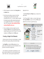
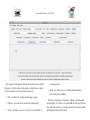
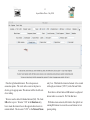
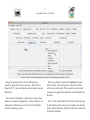
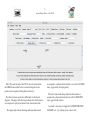
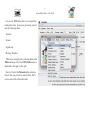
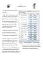
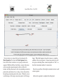
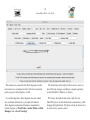
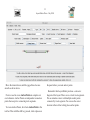
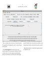
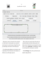
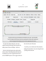
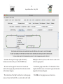
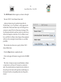
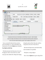
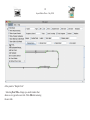
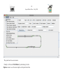
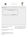
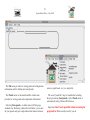
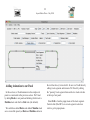
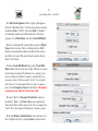
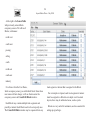
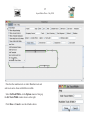
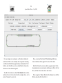
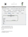
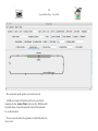
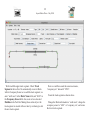
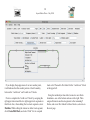
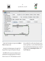
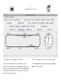
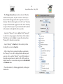
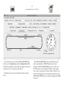
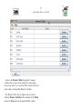
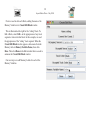
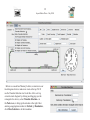
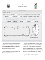
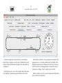
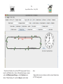
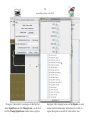
Using the JMRI/PanelPro Layout Editor
Dave Duchamp
Dick Bronson (Co-Presenter)
Bob Jacobsen (Co-Presenter)
A Clinic presented at the
NMRA National Convention, July 2008
Anaheim, California
1
Layout Editor Clinic - July 2008
Introduction
Layout Editor allows JMRI users to create animated
schematics of a model railroad layout. It is an alternative to
JMRI’s traditional Panel Editor. Layout Editor differs from
Panel Editor in several ways, including:
• Layout Editor uses a drawn track schematic, instead of
the icon based schematic used by Panel Editor,
• Layout Editor captures the full connectivity
automatically as the layout schematic is constructed,
• Layout Editor supports new animation features and
tools.
Layout Editor is similar to Panel Editor in many ways,
including:
• Both build on the same JMRI configuration items, such
as, turnouts, sensors, and signal heads.
PanelPro Layout Editor. It requires JMRI 2.1.7 or later. In
this clinic we go through the operations needed to:
• Create a Layout Editor Panel for a simple oval layout,
• Add animation to our simple oval panel,
• Add signals to the animated simple oval panel,
• Modify the panel background for use with a CTC panel.
Configuration/Panel Files
Associated with this postscript file are two layout
configuration/panel files. If you open these files in PanelPro,
you can see the panels that are built in this clinic. You can
also simulate a train running on the simple oval layout. You
can use these panels as starting points if you want to follow
along with the clinic. To use these associated files:
1. Start PanelPro (or another JMRI application).
Outline
2. In the preferences dialog, select Loconet Simulator. If
you’ve set up any Advanced Preferences items make
sure they are all turned off, so that the clinic files will
load correctly.
This clinic demonstrates many of the features of the JMRI/
3. Save preferences and restart the program.
• Both use the same icons for panel items other than the
track schematic.
2
Layout Editor Clinic - July 2008
4. After the program is restarted, select Load panels... in
the Panels menu.
5. In the file selection dialog, navigate to the folder
containing this postscript file and select either:
LayoutEditorClinic.xml - to view the simple oval panel,
the animation panel, and the animated signals panel,
or LayoutEditorClinicCTC.xml - to view the panel
with a CTC background. Do not load both without
restarting PanelPro in between.
6. You can simulate a train traversing the layout by
clicking the Run button on the animation panel, the
animated signals panel, or the CTC panel. To rerun the
simulation, click Pause, then click Run again.
Creating a Simple Oval Schematic
In this section we will create a track schematic of a simple
oval layout with a passing siding and an industrial spur.
Start PanelPro (or another JMRI application if you
prefer), and set the preferences to Loconet Simulator. Save
preferences and restart the application.
To save having to enter turnouts, signal heads, etc, into
tables, load LayoutEditorClinic.xml as described in steps
4 and 5 in the above section. Ignore the panels that are
displayed for now.
Select New Panel in the Panels menu, as shown in the
figure below.
The “Choose Editor” window (see lower figure) opens. Click Layout Editor to open a new Layout Editor panel.
Adjust the size of the new panel if necessary.
3
Layout Editor Clinic - July 2008
The top part of the panel contains the tool bar used to build
the panel. At the bottom of the panel is a help bar to explain
the user interface. Note the menus at the top:
• File - provides for saving and deleting a panel,
• Options - provides items used fairly infrequently,
• Tools - provides access to a variety of tools helpful in
creating panels.
• Help - provides access to detailed documentation
describing Layout Editor.
We start our simple oval panel by adding a right-handed
turnout (RH). To do this, we check RH on the top of the tool
bar, and click where we want the turnout to be located while
holding shift down (shift-click).
4
Layout Editor Clinic - July 2008
Note the right-handed turnout. The red squares are
connection points. The circle at the center is the place to
click to get its popup menu. This turnout will be the left side
of our siding.
We now need to add a left-handed turnout (LH). We check
LH on the top row. We enter “180” in the Rotation entry
box to make the turnout face in the opposite direction to its
normal default. We also enter “LT31” in the Turnout:Name
entry box. This links the turnout schematic to be created
with a physical turnout (“LT31”) in the Turnout Table.
Note that we did not link our RH turnout to a physical
turnout when we created it. We’ll do that later.
With these items entered, shift-click to the right of our
existing RH turnout to create the second turnout of our
passing siding.
5
Layout Editor Clinic - July 2008
We get the popup menu for our new LH turnout by
control-clicking on the circle at its center. Note that it is
linked to LT31. Also note that it has been rotated to face the
RH turnout.
The last line of the help bar explains how to drag an item
and how to summon its popup menu. The line shown is for
a Macintosh. Different lines will be shown for Windows
and Linux operating systems.
This is a good time to point out Location at the upper
left of tool bar. The x and y entries follow the location
of the cursor on the panel. This is useful in placing track
components in approximate alignment when adding them to
the panel.
Next we will add another LH turnout for our industry spur
by shift-clicking at the bottom of our simple oval schematic.
Note it will be assigned to LT32 and will not be rotated from
its default orientation.
6
Layout Editor Clinic - July 2008
Note: Physical turnouts, like LT32, must be entered into
the JMRI turnout table before a turnout diagram on the
panel can be assigned to that physical turnout.
The three turnouts are drawn differently on the layout
diagram. The upper left drawing indicates that the turnout is
not assigned to a physical turnout from the turnout table.
The upper right turnout drawing indicates that turnout
is assigned to a physical turnout that is set to the CLOSED
state (a gap in the diverging track).
The lower turnout drawing indicates that turnout is
assigned to a physical turnout that is in the UNKNOWN
state (gaps in both tracks).
A turnout’s state may be toggled, CLOSED/THROWN/
CLOSED/, etc., by clicking in its center circle.
7
Layout Editor Clinic - July 2008
Lets review JMRI tables that were set up before
starting this clinic. Items were previously entered
into the following tables:
Turnouts
Sensors
Signals and
Memory Variables.
Tables may be displayed by selecting them in the
Tables submenu of the main JMRI Tools menu, as
illustrated in the figure at the right.
Here we’ll select the Turnouts table and take a
look at what was previously entered there. We’ll
review some of the other tables later.
8
Layout Editor Clinic - July 2008
At the right is the top portion of the turnout table
requested above.
In JMRI “turnouts” correspond to outputs, which
can control track switches, but can also be used for
other output functions. In the table, LT1 through
LT12 are used for the green, yellow and red outputs
of signal heads defined in the Signals table. User
names are used to easily identify which output of
which signal head is referred to. There are more
signal head outputs below LT40. These can be
displayed by scrolling the table.
Of interest here are LT30, LT31, and LT32 which
correspond to physical track switches. These
turnouts (track switches) must be entered in the
Turnout table prior to being used in Layout Editor.
LT30, LT31, and LT32 were manually entered into
the table using the Add button. The other entries
were entered automatically as Signal Heads were
added to the Signals table. All User Names were
added manually when turnout items were created.
Note: New users may wonder why JMRI Lights are not
used for Signal Head outputs, instead of turnouts. The
answer is simple. Lights were introduced to JMRI long after
Signal Heads were introduced. When Signal Heads were
introduced, turnouts were the only type of output in JMRI,
so they were used. To date adding new features to JMRI has
taken precedence over re-engineering existing ones.
9
Layout Editor Clinic - July 2008
Our next step is to connect the top two turnouts with
Track Segments. We check the Track Segment check
box in the tool bar to indicate we’re going to add a track
segment. With the shift key held down, we press the mouse
on the top right connection point (red box) of the left
turnout, and drag the mouse to the corresponding connection
point on the right turnout. As we drag, a line is drawn from
the starting connection point to the cursor. When the cursor
is within range of the target connection point, it will change
shape. When this happens, release the mouse to complete
addition of the track segment. Connection point boxes will
turn green, indicating those connection points are “full”, i.e.,
have their maximum number of connections.
Note the second line of the help bar reminds us how to add
a track segment.
Add a track segment to complete the siding track.
10
Layout Editor Clinic - July 2008
The turnouts are connected with Track Segments, but the
two turnouts are not aligned correctly. The four connection
points are green, indicating they are full.
The bottom line of the help bar tells us how to move an
item. This item changes according to computer operating
system (MacOS X, Windows, or Linux).
It’s worth noting that a Track Segment does not contain
any coordinate information (x,y location information).
Track diagram coordinate information is maintained in
turnout diagrams, in Track Nodes (Anchor Points and End
Bumpers) and in Level Crossings.
We’ll move the right turnout down a little. For our
MacOS X system, we’ll hold down the command key, while
dragging the right turnout. The place to drag the turnout is at
its center circle, as shown above.
11
Layout Editor Clinic - July 2008
Move the turnout down, until the jagged lines become
smooth as shown above.
Next we need to create Anchor Points to complete our
oval schematic. Anchor Points are independent connection
points that accept two connecting track segments.
To create Anchor Points, first check Anchor Point in the
tool bar. Then with the shift key pressed, click at places on
the panel where you want anchor points.
Remember that Layout Editor produces a schematic
diagram of the layout. There are no curved track segments.
We can simulate corners with multiple anchor points
connected by track segments. You can use the cursor
location in the tool bar to help place anchor points.
12
Layout Editor Clinic - July 2008
The new anchor points are shown as red connection points.
To complete the oval diagram, they must be connected using
track segments.
Check Track Segment in the tool bar, click on one
connection point of the track segment, and drag to the other
(as shown above for a track segment connecting the first
anchor point to the throat connection point of the left upper
turnout). Remember not to release the mouse until the cursor
changes shape when the second connection point is reached.
Repeat this procedure to create all track segments needed
to complete the oval.
13
Layout Editor Clinic - July 2008
All the anchor points are connected to form a schematic
oval. Note that as two track segments were connected to
an anchor point, its connection square changed from red to
green indicating a full connection at that anchor point.
If your diagram needs alignment, move the anchor points
to align things. Follow the instruction in the help bar as we
did when we moved the right top turnout.
There is still one red connection point. We need to add
an industrial siding track at that connection point on the
industry turnout. For the other connection point of the siding
track, we create an End Bumper. An End Bumper is similar
to an anchor point, but only accepts one connection.
Check End Bumper in the tool bar, and click where the
industrial siding should end.
14
Layout Editor Clinic - July 2008
To complete the industrial siding track, add a track
segment connecting the diverging connection point of the
industry turnout to the new end bumper. (See above.)
Note how both the right upper turnout and the industry
turnout are drawn. The drawings indicate both turnouts are
in an unknown state. Click to toggle the turnout states of
each to CLOSED. The place to click to toggle a turnout is in
the circle at the center of the turnout.
If you like, you can verify the state of these turnouts by
looking in the turnout table. You can also change their state
by clicking in the turnout table
15
Layout Editor Clinic - July 2008
Schematic drawings of the upper right and industry
turnouts now indicate they are in the CLOSED state.
holding the control key down) on the turnout’s center circle
to show its popup menu.
We cannot set the upper left turnout to the closed state
until we first assign a physical turnout from the turnout table
to this turnout diagram.
Note that the popup menu tells us “No Turnout Set”. This
is replaced with the name of a turnout if a physical turnout is
assigned to the turnout diagram.
The bottom line of the help bar tells us how to show popup
menus of items. For MacOS X, we control-click (click while
Click Edit... in the popup menu as shown above.
16
Layout Editor Clinic - July 2008
The Edit Turnout window appears, as shown at the right.
We enter “LT30” in the Turnout Name field.
A physical turnout may be specified using either its
“System Name” or its “User Name”, as they appear in the
turnout table. The System Name may not be changed once
a turnout is created. The User Name may be changed. The
User Name should not be used here unless it is final, that is,
will not be changed at a later time. If a User Name is used
here, and if the User Name is later changed, the assignment
will be lost. By entering the System Name, we avoid that
possibility.
This window also allows us to specify a Block. We’ll
discuss Blocks later.
Click the Done button to complete the edit.
Click on the upper left turnout to toggle it to the CLOSED
state.
This clinic is being run using Loconet Simulator, without
a connection to a real layout. If a layout was connected,
and if the entered turnouts correspond to track switches on
the real layout, the track switch positions would change on
the layout when the corresponding turnout on the panel is
clicked.
17
Layout Editor Clinic - July 2008
By now, you should be familiar with the user interface
used by Layout Editor, so we don’t need the help bar at the
bottom any more. We select the Options menu, and uncheck
Show Help Bar in Edit Mode.
The Options menu provides for items not used very often.
The upper part consists of various check boxes, and the
lower part provides defaults and for adding and/or changing
infrequently used items. Most of these items could have
been put in the tool bar, but it’s fairly full as it is.
Each item in the Options menu is described in the Help
menu documentation for Layout Editor.
The help bar is no longer displayed.
Next we’ll use the Options menu again to change the title
18
Layout Editor Clinic - July 2008
of the panel to “Simple Oval”.
Selecting New Title... brings up a small window that
allows us to type in the new title. Click OK after entering
the new title.
19
Layout Editor Clinic - July 2008
The panel now has a new name.
Finally we’ll turn off Edit Mode by unchecking it in the
Options menu to see what our simple oval layout looks like.
20
Layout Editor Clinic - July 2008
Our schematic of the simple oval layout is shown, as it
would be displayed when in use.
The tool bar and the various connection point squares and
selection circles are not shown.
Note that it has taken far longer to describe how to draw
this track diagram, than it would take to redraw it now that
you know how!
If this were a layout diagram we wanted to preserve, we
would save it to disk at appropriate times to make sure we
don’t lose our work to computer or power gremlins.
21
Layout Editor Clinic - July 2008
The File menu provides for storing panel and configuration
information and for deleting unwanted panels.
sensors, signal heads, etc.) in a single file.
The Panels menu in the main PanelPro window also
provides for storing panel and configuration information.
The saved “panel file” may be loaded after restarting
the program using Load panels... in the Panels menu or
automatically using Advanced Preferences.
Selecting Store panels... in either menu will bring up a
standard store file dialog window that will allow you to store
all your panels and your configuration information (turnouts,
Important: Don’t load a panel file without restarting the
program first! Errors usually result if you do.
22
Layout Editor Clinic - July 2008
Adding Animation to our Panel
In this section, we’ll add animation to the simple oval
panel we constructed in the previous section. We’ll start
by adding Blocks to our panel and defining which track is
Mainline track and which is Side track (the default).
We could have added Blocks and defined Mainline track
as we created the panel (see Block and Mainline entries in
the tool bar above), but we didn’t. So now we’ll add them by
editing track segments and turnouts. We’ll start by editing
the “passing” track segment between the two track switches
at the top of our panel.
Select Edit... from the popup menu of the track segment.
Control-click (MacOS X) on a track segment’s selection
circle to get its popup menu.
23
Layout Editor Clinic - July 2008
The Edit Track Segment window (upper right) appears.
We select “Mainline Track” for this track segment, and keep
the default Style of “Solid”. (The other Style is “Dashed”,
for simulating tunnels and other hidden track.) We enter
“passing” for a Block:Name, and click Create/Edit Block.
Blocks are automatically created when you enter a Block:
Name for the first time. There is a Blocks table in JMRI.
Blocks are automatically added to the Block table when a
new Block is created. The entered name becomes the new
Block’s User Name.
Clicking Create/Edit Block brings up the Create/Edit
Block window shown at the lower right. A Block is a section
of track that is monitored by hardware for occupancy by a
train or rolling stock. Block occupancy is indicated by an
occupancy sensor, which is usually “Active” for occupied
and “Inactive” for unoccupied. Here we enter “occupancy
pass” as the Occupancy Sensor for this Block. The named
occupancy sensor must be in the Sensor table.
We select “Red” for Occupied Track Color, and leave
the default, “Black”, for Track Color (unoccupied track).
Track in this block will be drawn “red” if it is occupied, and
“black” if it is unoccupied, following its occupancy sensor.
We’ll skip Memory Variable Name: and come back to it
later. Complete the edit by clicking Done in both windows.
24
Layout Editor Clinic - July 2008
At the right is the Sensor Table
with previously entered block
occupancy sensors. We will use 8
Blocks, with names:
north west
south west
passing
siding
south
north east
south east
industry
It’s obvious from the User Name,
which occupancy sensor goes with which block. Since these
user names will not change, we’ll use them to enter the
occupancy sensors in Create/Edit Block windows.
Each Block may contain multiple track segments and
possibly a turnout. Each Block needs to be set up only once.
The Create/Edit Block window may be requested from any
track segment or turnout that is assigned to the Block.
For our simple oval panel, each track segment or turnout
must be assigned to a Block in our simple oval. In actual
layouts, there may be unblocked areas, such as yards.
Blocks are very useful for animation, and are essential for
setting up signal logic.
25
Layout Editor Clinic - July 2008
Note that the mainline track is wider. Mainline track and
side track can be drawn with different widths.
Select SetTrackWidth... in the Options menu to bring up
the Set Track Width window shown at the right.
Click Done or Cancel to use the defaults shown.
26
Layout Editor Clinic - July 2008
For our simple oval schematic, we’ll add text labels for
each block. This is not normally done on panels. Labeling
our Blocks will afford an opportunity to demonstrate Text
Labels, and will allow you to see what Block is located in
what area of our schematic panel.
To add a Text Label, we check Text Label in the tool bar,
and enter the text to be shown. In the example above, we’ve
entered “passing” as our text.
Now, create the Text Label. While holding shift down,
click at the desired the upper left corner of the label.
Each Text Label is an icon, and has a popup menu. From
its popup menu you can inspect and change its Font, its Font
Size, its Font Color and various other items.
Next assign the “siding” Block to the siding track, edit that
Block, and add a Text Label for it.
27
Layout Editor Clinic - July 2008
Two Blocks are assigned and labeled. Now we need to
provide a new Anchor Point on the left side to serve as the
block boundary between the “north west” and the “south
west” blocks.
Start by deleting the track segment on the left side by
selecting Remove in its popup menu.
28
Layout Editor Clinic - July 2008
The connection point squares are now drawn red.
Add the new Anchor Point that will serve as our block
boundary. Select Anchor Point in the tool bar. With the shift
key held down, click at the point the Anchor Point should
be, as shown above.
Now we need to add track segments to rebuild the left side
of our oval.
29
Layout Editor Clinic - July 2008
We first add the upper track segment. Check Track
Segment in the tool bar. To automatically create its Block
with its Occupancy Sensor as we add the track segment, we
enter “north west” in the Block: Name field, and “LS10” in
the Occupancy Sensor field. Also, note we have checked
Mainline in the Tool Bar. Making these entries before the
track segment is created will save time by not having to edit
the new track segment.
Note we could have used the sensor user name,
“occupancy nw” instead of “LT10”.
Create the track segment as shown above.
Change the Block information to “south west”, change the
occupancy sensor to “LS11” or “occupancy sw”, and create
the lower track segment.
30
Layout Editor Clinic - July 2008
If you display the popup menu of our new anchor point,
it will indicate that this anchor point is a block boundary
between the “north west” and “south west” blocks.
Next we complete the “north west” block by assigning the
right upper turnout and the two right upper track segments to
this block. Also, when editing the two track segments, select
Mainline. While editing the turnout or either track segment,
click Create/Edit Block, and select “Red” for its occupied
track color. Then add a Text Label for the “north west” block
at the upper left.
Using the methods just described, create two new block
boundaries--one at the bottom and one on the right. Then
assign all turnouts and track segments to the remaining 5
blocks, and create Text Labels for those blocks, as shown on
the next page.
31
Layout Editor Clinic - July 2008
Your simple oval with Blocks should be similar to that
shown above.
This clinic is using Loconet Simulator, without a
connection to a real layout. However, we can simulate a
train traversing our simple oval layout using a Logix. Our
Logix simulates the train by changing occupancy sensors
and turnout states according to the time shown on the JMRI
Fast Clock.
Explaining how Logix works is beyond the scope of this
clinic. You can view our Logix by displaying the Logix
table using the PanelPro Tools menu, then clicking the Edit
button next to the Logix.
Here, we need to add a Fast Clock display to our panel.
32
Layout Editor Clinic - July 2008
To add a Fast Clock display to our panel, select Add Fast
Clock in the Options menu.
An analog fast clock display appears at the upper left of
the panel. Move it (drag it) to the right side of the panel.
The JMRI Fast Clock was previously defined to start at
8:00 AM, and to load stopped (paused) at 8:00. The Fast
Clock rate was set to 16:1. This information was saved in
the LayoutEditorClinic.xml file, along with panels, sensors,
turnouts, signal heads, etc., and was loaded when that panel
file was loaded. Fast Clock information may be viewed and
changed by selecting Clocks>Setup Fast Clock... in the
PanelPro Tools menu.
33
Layout Editor Clinic - July 2008
Our analog fast clock display is at the right.
We need to add a button to our panel that we can use
to start the fast clock and run our simulation. We’ll use a
Sensor Icon linked to the Fast Clock’s ISCLOCKRUNNING
internal sensor. When this sensor is toggled, the fast clock
switches from run to pause, etc.
First we’ll change the sensor icons to button images.
Check Sensor Icon in the tool bar, and click Change
Icons... as shown above.
34
Layout Editor Clinic - July 2008
The Change Sensor Icons window is shown. When the
window is first opened, only the “resources” directory is
shown. Click the toggle at the left to open the “resources”
directory. Then click the toggle next to the “icons” directory
to open it. Then click the toggle next to the “misc” directory
to open it. The lower part of your window should be similar
to the window at the right. (Scroll as needed.)
Assign the “Pause.gif” icon to Active. Click “Pause.gif”
to select it--its image appears at the bottom of the window.
Click the icon next to Active: to assign the selected icon,
“Pause.gif” to the active sensor state.
Assign “Run.gif” to Inactive by first selecting it, then
clicking the icon next to Inactive.
After a Sensor Icon is created using these assignments,
the “Pause.gif” icon will be displayed when the assigned
sensor is Active, and the “Run.gif” icon will be displayed
when the assigned sensor is inactive. We will be using an
internal sensor, so we need not assign icons to Inconsistent
or Unknown states.
Close the window by clicking appropriately in the upper
window bar.
35
Layout Editor Clinic - July 2008
To create the sensor icon, enter ISCLOCKRUNNING in
the box next to Sensor Icon, and check Sensor Icon. With
the shift key held down, click where the upper left corner of
the sensor icon is to be placed. (See above).
Under the new sensor icon, add a Text Label as shown
above.
The ISCLOCKRUNNING sensor is linked to the fast
clock automatically by JMRI. When the fast clock is
running, the ISCLOCKRUNNING sensor is active, and
the “Pause.gif” icon is displayed. When it’s not running
(as it is now), the sensor is inactive and the “Run.gif” icon
is shown. Clicking the sensor icon changes the state of the
ISCLOCKRUNNING sensor, starting or stopping the JMRI
fast clock.
36
Layout Editor Clinic - July 2008
We could stop at this point and run the train simulation,
but instead we’ll add Train Tracking animation.
Train Tracking allows us to display dynamically which
train is in an occupied Block. So for one train, or for several
trains transiting a layout at the same time, we can show
where each train is at any given time.
Train Tracking is based on the Block software developed
by Bob Jacobsen prior to the development of Layout Editor,
and primarily used with scripts. Basically, each occupied
Block has a value. This value is automatically passed from
Block to Block as a train moves from Block to Block, and
is cleared when a Block is no longer occupied. So the value
follows the train around the layout. Setting value to a train
name, passes the train name around from Block to Block.
Layout Editor has expanded Bob’s original Block software
by adding a tool to automatically initialize each Block,
creating needed Path and Bean Settings objects. This
initialization (previously done in scripts only) is needed to
make the Block system work. Since Layout Editor captures
the full connectivity of its panel, it has the information
needed to perform this initialization automatically. The
initialization is performed when Blocks are changed or
when a panel file is loaded. (Since it’s automatic, Layout
Editor users don’t need to be concerned about Path and Bean
Settings objects.)
Layout Editor also provides software to allow a Memory
Variable to be assigned to each Block. When the value of a
Block changes, Layout Editor automatically copies the new
value of the Block into its assigned Memory Variable (if
there is one).
So, by using a Memory Label near each Block, we can
display the name of the train in that Block.
This might sound complicated, but it’s very easy to set up
because the JMRI Block and Layout Editor software does
almost everything automatically. There is even software to
automatically save and restore Block values between runs of
the program.
Since our panel is already blocked, all we need to do to
implement Train Tracking on our simple oval panel is:
1. Create the Memory Variables (they are already in the
Memory Variables Table),
2. Assign one of the Memory Variables to each Block,
3. Place a Memory Label near each Block in our panel.
37
Layout Editor Clinic - July 2008
Above is the Memory Table showing the 8 memory
variables that were previously defined. To make things
easy to keep track of, we used our Block names for the user
names of the corresponding Memory Variables.
The Memory Table may be displayed at any time by
selecting Memory Variables in the submenu of the Tables
item in the Tools menu of the main PanelPro window.
38
Layout Editor Clinic - July 2008
Next we need to edit each Block, adding the name of its
Memory Variable in its Create/Edit Block window.
This is illustrated at the right for the “siding” block. To
Edit a Block, select Edit... in the popup menu of any track
segment or turnout in that block. In this example, we used
the popup menu of the “siding” track segment. When the
Create/Edit Block window appears, add a name from the
Memory table in Memory Variable Name:, then click
Done. Then click Done in the Edit window that was used to
summon the Create/Edit Block window.
Our next step is to add Memory Labels for each of the
Memory Variables.
39
Layout Editor Clinic - July 2008
Before we can add our Memory Labels, we must move our
track diagram down to make more room at the top. We’ll
use the Translate Selection tool to do this. After selecting
our entire track diagram by clicking and dragging (see the
rectangular box above), select Translate Selection... in
the Tools menu, to bring up the window at the right. After
entering an appropriate number in Vertical (y) Translation:,
click Move Selection to do the translation
40
Layout Editor Clinic - July 2008
The track diagram is now 25 pixels lower. Note: if the
translation was not satisfactory, you can reverse it by
selecting Undo Translate Selection in the Tools menu
immediately after translating a selection.
Next we need to add Memory Labels near each of the
Block names in our track schematic.
To do this, check Memory Label in the tool bar. Then for
each Memory Label, enter the name of one of the Memory
Variables, either System Name or User Name, in the text
field following Memory Label. While holding shift down,
click the location of the upper left corner of the new memory
label, placing it near its corresponding Block text label.
Repeat for each of the 7 other memory labels.
41
Layout Editor Clinic - July 2008
A small rectangle shows the location of each memory
label. These rectangles are only shown in Edit Mode. Each
memory label automatically expands to the right when text
is displayed.
Hovering the cursor over each rectangle shows the name
of the Memory Variable assigned to that memory label.
Each memory label also has a popup menu, similar to the
popup menu we’ve already mentioned for text labels. This
popup menu provides for changing text font style, font size,
and/or font color. Use popup menus to change the color of
each memory label to “Red”, and the style to “Bold”.
Memory labels can also be moved (repositioned) like other
items in the track schematic.
42
Layout Editor Clinic - July 2008
On to the demo of a train running around our oval.
To initialize things, place a train in the “siding” block. To
do this:
1. Enter a train name in the Block Table, and
2. Set the block’s occupancy sensor to Active. (This need
not be done with a real layout connection. The occupancy
sensor will reflect the presence of a train automatically.)
We enter the train name, here we’ll just use “Train”, in the
Value column of the “siding” Block of the Block Table as
shown above. Remember to click somewhere outside the
value entry after typing in the train name to make Java
read what you entered. (The Block Table is opened using
the Tables item in the Tools menu of the main PanelPro
window.) Close the Block Table.
Next we open the Sensor Table (see page 24) and set the
state of the “occupancy side” sensor to Active. This tells
JMRI that the “siding” block is occupied. Close the Sensor
Table.
43
Layout Editor Clinic - July 2008
After turning off Edit Mode using the Options menu,
the above panel is displayed. Track in the “siding” block is
displayed Red, indicating that this block is occupied. Also,
the train name is displayed next to the “siding” Block.
We’re now ready to run the train simulation. Switch to the
PanelPro program from the application reading this pdf file.
If the panel shown above is not displayed, go to the Show
Panel > item in the Panels menu of the main PanelPro
window, and select Simple Oval w/Animation.
Click Run to start the simulation. Our Logix will simulate
the train making two transits of the oval, and returning to
the “siding” Block. Track color changes as the train enters
and exits each Block. After the simulation is complete, click
Pause. Click Run to run the simulation again.
44
Layout Editor Clinic - July 2008
Adding Signals and Signal Logic
We’ll use Layout Editor’s Set Signals at XXX... tools to
place signals and setup signal logic for these signals. Layout
Editor’s five Set Signals at XXX... tools may be accessed
using Layout Editor’s Tools menu, however, except for
the Set Signals at Throat-to-Throat Turnouts... tool, it’s
best to access them using the popup menus of turnouts and
anchor point block boundaries.
We’ll start by selecting Set Signals... in the popup menu of
our left upper turnout. This brings up the window shown on
the next page.
45
Layout Editor Clinic - July 2008
The main purpose of this window (and all Set Signals
windows) is informing Layout Editor which signal head is
assigned to which function. Two automated options are also
available to help in setting up signaling.
1. Add Signal Icon to Panel - Will place an icon for an
entered Signal Head on the panel at a reasonable position
near the turnout. Icon positions may be adjusted by
manually moving them. Signal icon images may be changed
before they are added to the panel by 1) checking Signal
Icon in the Tool Bar, 2) clicking Change Icons..., and 3)
following a procedure similar to that used to change the
Pause/Run icons previously.
2. Set up Logic - Will set up Simple Signal Logic, SSL,
for the Signal Head. SSL supports ABS signalling. SSLs set
up by Layout Editor usually need no adjustment, however,
in special situations manual editing may be needed. The SSL
for a Signal Head may be viewed/edited by selecting Edit
Logic... in the popup menu of its signal head icon.
Layout Editor doesn’t have enough information to set up
signal logic until Signal Heads are set in adjacent Blocks.
So we’ll first go through setting and placing Signal Heads at
every block boundary, then return later to set up the logic for
these signals.
Prior to entering them in a Set Signals window, Signal
Heads must be in the Signal Table. The Signal Heads
entered above were previously entered into the Signal Table.
Click Done to add icons for these Signal Heads to the panel.
46
Layout Editor Clinic - July 2008
Our pre-entered Signal Table is shown at the right.
Each Signal Head was assigned a User Name that indicates
where the Signal Head is placed. This makes it easy to keep
track of the function and location of each Signal Head.
All Signal Heads are “Triple Output” type. The three
outputs for each Signal Head are shown in the Turnout
Table.
47
Layout Editor Clinic - July 2008
Four Signal Heads are placed around our left upper
turnout. The positions of these Signal Heads may be
adjusted manually. The icons are shown “Dark” because
the signal logic is not set up and working yet. (Note:
if you are following along in PanelPro after loading
LayoutEditorClinic.xml, you’ll see colors instead of “Dark”,
because the signal logic was included in that file, and you’ll
see Signal Head names automatically displayed in Set
Signals at XXX windows because that information was also
in the panel file.)
Next we’ll set the signals at the block boundary on the left
by selecting Set Signals... in the popup menu of the anchor
point that divides the “north west” and “south west” blocks.
48
Layout Editor Clinic - July 2008
The Set Signals at Block Boundary window is displayed.
After entering the two required Signal Head names and
checking Add Signal Icon to Panel below each Signal Head
name, click Done to tell Layout Editor those Signal Heads
serve the designated function and to place signal head icons
on the panel.
Repeat this procedure to set Signal Heads and place signal
head icons at the other four block boundaries:
anchor point - “south west” to “south”,
industry turnout - “south” to “south east” and “south” to
“industry”,
anchor point - “south east” to “north east”,
upper right turnout - “south east” to “passing” and “south
east” to “siding”.
With signal head icons placed, and Layout Editor knowing
which Signal Heads serve which function, there is enough
information to set up signal logic. To do this, we revisit each
of the turnouts and anchor point block boundaries.
Our revisit of the upper left turnout is shown on the next
page.
49
Layout Editor Clinic - July 2008
The window is shown with the Signal Head names already
in place.
Uncheck Add Signal Icon to Panel under each Signal
Head name, because the icons for the named Signal Heads
are already on the panel.
Check Set up Logic under each Signal Head name.
Click Done to set up the signal logic.
Repeat this at the other turnout and anchor point block
boundaries. As signal logic is set up, signal head icons will
show as colored icons.
Layout Editor sets up Simple Signal Logic (SSL) for each
Signal Head. SSL supports ABS signalling.
50
Layout Editor Clinic - July 2008
All signals are placed, and ABS signal logic is functioning!
Note we have also changed the title of this panel.
Using Layout Editor’s tools, adding signals to our
animated simple oval panel was quick and pain free.
Now we’re ready to re-run our train simulation.
Uncheck Edit Mode in the Options menu.
51
Layout Editor Clinic - July 2008
We’re now ready to re-run our train simulation.
Switch to the PanelPro program from the application
displaying this pdf file. If the panel displayed above is not
shown, go to the Show Panel > item in the Panels menu of
the main PanelPro window, and select Layout Editor Clinic
- Full Signals.
As before, click the Run button to run the simulation.
Since the siding track shows occupied and “Train” is
displayed in its memory label, we do not need to re-initialize
the simulation.
52
Layout Editor Clinic - July 2008
Adding a CTC Panel Background
We’ll now add a background suitable for a CTC panel
using Dick Bronson’s “multi-slice” method. Note: we
removed Block names and Memory Labels, and extended
the panel in the vertical direction. (We’ll put the Memory
Labels back in later.) The panel shown above and on the
next few pages is clipped at the bottom, to provide room
for this text. Adding backgrounds is the only CTC support
currently offered by Layout Editor, but the manual methods
to continue on in Dick’s clinics apply here also.
To begin, select Add Background Image... in the Options
menu.
53
Layout Editor Clinic - July 2008
A standard file selection window opens up to allow
us to select a background file. This window varies with
operating system.
The window will begin with the “resources” or with
the “icons” directory. Navigate to the “background”
directory, which is found in the “USS” directory of the
“icons” directory. The “icons” directory is found in the
“resources” directory of the JMRI directory.
Each of the “Panel-” files corresponds to a vertical
slice of the CTC background. To complete a
background, we start with the left-most slice, and keep
adding slices across the panel, until we finish with the
right most slice. When a slice is added, Layout Editor
automatically places it to the immediate right of the
previously entered slice. The first slice is placed at the
upper left of the panel.
Note that there are two sets of slices in the “background”
directory, those with a “-9” in the name, and those without
the “-9”. You can use either set, but should not mix slices
across sets. Here we’ll use the set without the “-9” in the
names.
Begin by selecting “Panel-left.gif”, as shown to the right.
click Open to add this slice to the panel.
54
Layout Editor Clinic - July 2008
Note the left border slice of the CTC background. Next we
need to add blank slices, slices without plate images. Again,
select Add Background Image... in the Options menu.
Select “Panel-blank.gif”, and click Open to add a blank
slice.
Repeat this two more times to add two more blank slices
of CTC background.
55
Layout Editor Clinic - July 2008
Note problems with centering and color. The track
schematic is too high in the background image, and the
tracks and signals are black on black.
56
Layout Editor Clinic - July 2008
We use the Translate Selection... tool in the Tools menu
to lower the track diagram (see page 39).
Next, set Default Track Color > in the Options menu to
“White”, so edit circles will show up on the background.
57
Layout Editor Clinic - July 2008
Next, open Create/Edit Block for each of our eight
blocks and change Track Color: to “White” (see page 38 to
remember how to bring up these windows. This will make
all unoccupied track visible. Now for Signal Heads.
58
Layout Editor Clinic - July 2008
Change to “short-white” icon images. In the Tool bar
check Signal Icon and click Change Icons... in the Tool
bar. The Change Signal Icons window (above right) is
displayed. After changing icons, use Set Signals... at each
anchor point block boundary and turnout (above left) to
replace the signal icons with the “short white” ones
59
Layout Editor Clinic - July 2008
Add a background slice with switch and signal plates for
the upper-left turnout.
Next add more blank slices and two switch and signal plate
slices for the other two turnouts, then add a right end slice.
60
Layout Editor Clinic - July 2008
Above is our finished CTC background. Before exiting
Edit Mode, we changed the panel title, and used Translate
Selection... to stretch the track diagram to the right to align
turnouts over their plates. The text label color under the
fast clock was also changed. This panel is found by loading
LayoutEditorClinicCTC.xml into PanelPro.
61
Layout Editor Clinic - July 2008
Our CTC panel needs to be completed manually.
Procedures for adding “levers” and “jewels” to the plates
shown above for Panel Editor type CTC panels are given in
clinics by Dick Bronson. These procedures are very similar
for Layout Editor type CTC panels. Layout Editor tools to
automate these procedure are possible future additions to
Layout Editor.
Future Layout Editor Development
We’ll conclude our clinic with a brief discussion of the
future. Layout Editor development is continuing. Possible
directions include:
1. Automated setup for automatically running trains around
the layout. Using Layout Editor’s connectivity information
should facilitate a reasonably easy user interface for setting
up transit paths for automated running of trains.
2. Linked to the above, is automated addition of APB
signal logic to the ABS signal logic demonstrated in this
clinic.
3. Development of a tool for automated placement of
levers and jewels on a Layout Editor CTC panel with
backgrounds made using the multi-slice method.
4. Development of a tool for automated setup of the logic
for operating the CTC switch and signal plates.
5. ??? User suggestions. JMRI developers continue to be
very interested in user suggestions. These often come in
via the Yahoo jmriusers list. User suggestions have led to
addition of many JMRI features, including some in Layout
Editor.
In this clinic, we’ve only been able to cover a part of
Layout Editor. You will probably need some of what was
not covered when you use Layout Editor to build a panel for
a real layout. To build on what you’ve learned here, please
make use of documentation provided via the Help menu
of the main Layout Editor window. And be sure to look at
the detailed documentation available in the Help menus
of Layout Editor’s other windows, especially windows
shown when tools are selected or components are edited.
For example, there is detailed information on how to handle
crossover turnouts and double slip turnouts in Help menu
documentation, as well as answers to many other Layout
Editor questions.
Thanks for your interest in Layout Editor and in this clinic.