1
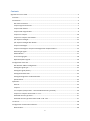
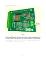
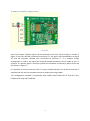
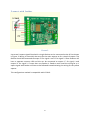
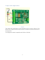
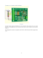
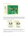
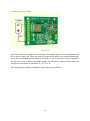
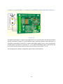
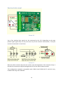
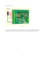
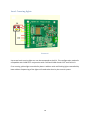
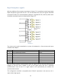
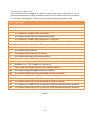
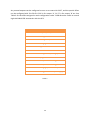
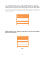
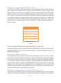
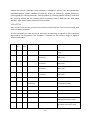
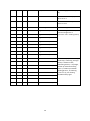
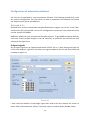
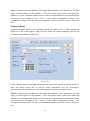
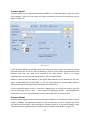
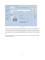
Signalist SC1
DCC signal controller user manual
Covers configuration for UK signals
1
Contents
Signalist SC1 user manual ...............................................................................................................................5
Overview .....................................................................................................................................................5
Connections ................................................................................................................................................5
DCC track connection..............................................................................................................................6
2-aspect signal connections ....................................................................................................................7
2-aspect with feather..............................................................................................................................8
3-aspect with single feather ...................................................................................................................9
3-aspect or 4-aspect .............................................................................................................................10
3-aspect or 4-aspect with feathers .......................................................................................................11
2/3-aspect searchlight ..........................................................................................................................12
2/3-aspect searchlight with feather .....................................................................................................13
4-aspect searchlight ..............................................................................................................................14
3-aspect searchlight or 4-aspect searchlight with multiple feathers ...................................................15
Position light signal ...............................................................................................................................16
SPAD indicator ......................................................................................................................................17
Level Crossing lights ..............................................................................................................................18
Dapol Semaphore signals ......................................................................................................................19
Configuration of the SC1 ...........................................................................................................................20
DCC decoder address configuration .....................................................................................................20
Setting the signal type ..........................................................................................................................22
Setting the signal polarity .....................................................................................................................23
Setting the default state .......................................................................................................................23
Setting the brightness of individual LEDs..............................................................................................23
Special effects .......................................................................................................................................23
Operation ..................................................................................................................................................25
General..................................................................................................................................................25
2-aspect.................................................................................................................................................25
3 or 4-aspect (except CV38 = 7 and extended accessory protocol) ......................................................26
3-aspect or 4-aspect when CV38 = 7 or 11 ...........................................................................................27
Extended accessory protocol ................................................................................................................27
Extended accessory protocol when CV38 = 128 - 134 ..........................................................................27
List of CVs ..................................................................................................................................................28
Configuration of automation software .....................................................................................................30
Railroad & Co ........................................................................................................................................30
2
JMRI ......................................................................................................................................................34
RocRail ..................................................................................................................................................39
Specification..............................................................................................................................................47
Additional support ....................................................................................................................................48
3
4
Signalist SC1 user manual
Overview
The signalist SC1 is a highly versatile DCC accessory decoder optimised for driving LED based
signals and will drive any LED based signal that will operate from a 5V supply. The SC1 can
typically drive up to eight signal lamps in various configurations allowing the connection of
up to four 2-aspect signals, two 3-aspect signals or two 4-aspect signals. The flexible output
configuration can drive searchlight and position light signals using multicolour LEDs as well
as feathers with a correct common centre lamp. Configuration of signal type and address is
by standard programming of configuration variables on the DCC programming track
connection from a command station or dedicated DCC programmer such as a Sprog.
Connections
The following section shows how to connect the SC1 to the signals and DCC system. The
diagrams all show common cathode wiring but if common anode signals are used the
common wire should be connected to terminal ‘a’ instead of terminal ‘k’.
5
DCC track connection
FIGURE 1
Only the DCC signal is required to control and power the SC1 via terminal block J2. Normally
this will be connected to the accessory bus, but if you do not have a separate accessory bus
it can be connected to the track bus or just to the track adjacent to the signal. When
programming the SC1, J2 will need to be connected to the programming track output of the
command station instead of to the track output.
6
2-aspect signal connections
FIGURE 2
Up to four simple 2-aspect signals can be attached to the SC1. The first signal is shown in
Figure 2 with the red LED connected to terminal ‘A’, the green LED connected to terminal
‘B’, and the common cathode wire connected to terminal ‘k’. If a common anode
arrangement is used in the signal the common anode connection can be made to the ‘a’
terminal. If a distant signal is used the yellow LED should be connected in place of the red
LED shown in Figure 2.
It is possible to connect the two LEDs in inverse parallel between the A and B terminals if
required and not use the common terminal to make the wiring simpler.
This configuration method is compatible with CV38=0 (and CV38=14 E+F and G+H only,
CV38=6 G+H only) and CV38=129.
7
2-aspect with feather
FIGURE 3
Up to two 2-aspect signals fitted with a single feather can be connected to the SC1 as shown
in Figure 3. Wiring is essentially the same for the main aspects as for a simple 2-aspect. The
feather should be connected to output ‘D’ for signal 1 and ‘H’ for signal 2. Some feathers will
have a separate common LED and this can be connected to output ‘C’ for signal 1 and
output ‘G’ for signal 2. If more than one feather is fitted to each head the wiring for a 4aspect signal with feather will have to be followed instead omitting the wiring for the yellow
aspects.
This configuration method is compatible with CV38=2.
8
3-aspect with single feather
FIGURE 4
Two 3-aspects with single feathers can be connected to the SC1 as shown in Figure 4. If the
feathers have a separate common lamp connection it should be connected to terminal D or
H as appropriate.
This configuration method is compatible with CV38=9 or CV38=130.
9
3-aspect or 4-aspect
FIGURE 5
Two 4-aspect signals can be connected to the SC1 as shown in Figure 5. If 3-aspect signals
are used there will be no connection to outputs ‘D’ or ‘H’ and any attempt to display double
yellow will result in single yellow being displayed instead.
This configuration method is fully compatible with CV38=1, 7, 11, 14 (A-D only) and 128.
10
3-aspect or 4-aspect with feathers
FIGURE 6
A single 4-aspect signal with feathers can be connected, with provision for up to three
feathers. If a prototypically correct common centre lamp is used it should be connected to
output ‘E’.
This configuration method is compatible with CV38=3, CV38=133 (and CV38=6 single feather
only).
.
11
2/3-aspect searchlight
FIGURE 7
Up to four 2-aspect searchlight signals or 3-aspect searchlight signals can be connected to
the SC1 as shown in Figure 7. 2-aspect searchlight signals may or may not have a common
connection as shown in Figure 8, and if not there is no need to make a common connection.
3-aspect must have common anode or cathode.
FIGURE 8
The yellow aspect is achieved by turning on both the red and green LEDs at once. Careful
adjustment of the brightness CVs will enable the best yellow colour to be displayed.
This configuration method is compatible with CV38=0 (2-aspect only), CV38=8 (3-aspect) or
CV38=129 (3-aspect extended protocol).
12
2/3-aspect searchlight with feather
FIGURE 9
Up to two 2-aspect or 3-aspect searchlight signals with a single feather can be connected to
the SC1 as shown in Figure 9.
This configuration method is compatible with CV38=2 (2-aspect) and CV38=131 (3-aspect
extended protocol).
13
4-aspect searchlight
FIGURE 10
Up to two 4-aspect searchlight, or two 3-aspect searchlight signals can be connected to the
SC1 as show in Figure 10. There may only be a single connection for the second yellow lamp,
but if two are provided and connected to terminals ‘C’ and ‘D’ the colour can be adjusted as
for the main lamp. 3-aspect searchlight signals will not have a second yellow lamp and
therefore no connection to terminals ‘C’, ‘D’, ‘G’ or ‘H’
This configuration method is compatible with CV38=4 and CV38=132.
14
3-aspect searchlight or 4-aspect searchlight with multiple feathers
FIGURE 12
A 4-aspect searchlight or 3-aspect searchlight with up to three feathers can be connected to
the SC1 as shown in Figure 12. If the feathers have a separate common lamp connection it
should be connected to terminal E. 4-aspect searchlight signals may or may not have the
second yellow’ connection to terminal ‘D’. If a 3-aspect searchlight signal is used there will
be no second yellow aspect and therefore no connection to terminals ‘C’ or ‘D’.
This configuration method is compatible with CV38=5 and CV38=134.
15
Position light signal
FIGURE 13
Up to four position light signals can be connected to the SC1. Depending on the type
position light signals may or may not have any of the common connections; if not just
connect to terminals ‘A’ and ‘B’ etc.
FIGURE 14
With the white common lamp the 1K resistor sets the brightness of the common lamp. It
will then be necessary to adjust the brightness CVs for the other lamps to match.
This configuration method is compatible with CV38=0 (and CV38=14 E+F and G+H only,
CV38=6 G+H only) and CV38=129.
16
SPAD indicator
FIGURE 15
Up to two SPAD indicators can be connected to the SC1. This configuration method is
compatible with CV38=13 in conjunction with CV56 and CV60=3 and CV57 and CV61=12.
17
Level Crossing lights
FIGURE 16
Up to two level crossing light sets can be connected to the SC1. This configuration method is
compatible with CV38=12 in conjunction with CV56 and CV60=3 and CV57 and CV61=12.
First crossing yellow light controlled by base+1 address with red flashing lights controlled by
base address. Sequencing of the lights will need to be done by the control system.
18
Dapol Semaphore signals
With the addition of the simple circuit shown in Figure 17 it is possible to control up to eight
Dapol semaphore signals with the SC1. The red and black wires from the signals should be
connected to 16V AC as recommended by Dapol or regulated 9V DC, and the yellow wires
should be connected in pairs as shown below in figure 17.
FIGURE 17
The circuit can be easily assembled on a piece of stripboard in a few minutes with parts
available from Maplin:Quantity Part
Maplin ref
2
ILQ74 Quad opto isolator
YY63T
1
Stripboard
FL17T
11
Terminal 2W
RH80B
1
Terminal 3W
RH81C
8
Push button
KR90X
2
16-pin IC socket
BL19V
The SC1 should maintain synchronisation with the signal once set up even during power
outages to the SC1, but if power is lost to the signal while the SC1 is powered
synchronisation may be lost. If a signal needs to be synchronised just activate the
synchronisation button.
This configuration method is compatible with CV38=15. Operation is the same as for 2aspect colour light signals.
19
Configuration of the SC1
Configuring the SC1 is quite straightforward and may be as simple as just setting the DCC
address.
DCC decoder address configuration
The SC1 occupies a contiguous block of up to eight accessory addresses and can be set to
use any accessory address or extended accessory address. The address is set in CV1 and
CV9. The SC1 supports both decoder address mode and output address mode. The address
mode can be changed with CV29.
Setting the address with decoder address mode (default) when CV29=128
With the default setting of CV29=128 and CV9=0 it is possible to simply set the decoder
address to any address between 1 and 63 by writing the decoder address to CV1. This will
allow the use of accessory addresses 1-252. If accessory addresses are required outside this
range it will be necessary to change CV9 as well.
The values of CV1 and CV9 can be calculated from the following formula:First accessory address = CV9 x 256 + CV1 x 4 – 3
With CV29 set to 128 values of CV1 above 63 are not allowed, and 63 will not work for
configurations that use more than four addresses. CV9 can have values 0-7, values above 7
are not allowed.
See note overleaf about variations in addressing used in some command stations.
Setting the address with output address mode when CV29=192
If you change CV29 from the default to 192 the effect of CV1 will change. With CV9=0 it is
now possible to write a value between 1 and 255 to CV1 which will allow the use of
accessory addresses 1-258. If accessory addresses are required outside this range it will be
necessary to change CV9 as well.
The values of CV1 and CV9 can be calculated from the following formula:First accessory address = CV9 x 256 + CV1
CV9 can have values 0-7, values above 7 are not allowed. With CV29 set to 192 CV1 can
have any value between 1 and 255, but values above 248 will not work for some
configurations.
See note overleaf about variations in addressing used in some command stations.
20
Setting the address automatically
It is possible to set the decoder address automatically using the PGM jumper. To set the
address automatically use the following steps.
1.
2.
3.
4.
Power off the SC1.
Fit the PGM jumper to pins 1 and 2 of J5.
Power on the SC1.
Operate the desired base address on your command station to both Normal and
reverse.
5. Power off the SC1.
6. Remove the PGM jumper.
7. Power on the SC1
The address will now be set in CV1 and CV9 in output address mode with CV29 set to 192.
The decoder will respond to contiguous addresses starting with the one that was operated.
The jumper must be removed for normal operation.
Normal operation
Jumper fitted for programming
Figure 18 - PGM jumper J5 location
Important note: -
Many command stations and some software
applications do not follow the NMRA accessory numbering scheme, so it is important to be
aware that setting the address CVs according to the NMRA formulae used above may not
work and some addresses may not be accessible. Lenz, ESU and ZTC are notable in this
respect and you will need to make allowance. Some systems can only operate a subset of
the accessory range, often limited to addresses below 256 or below 1024 so this may need
to be taken in to account also before choosing addresses. If you are not sure how the
addressing works on your system use the automatic address setting mode with the PGM
jumper.
21
Setting the signal type
The SC1 needs to be configured to match the signal type that is connected to the J1
terminals by adjustment of CV38. By default CV38 is set to zero which allows the connection
of up to four 2-aspect signals. Table 1 shows the different settings allowed in CV38.
CV38
0
1
2
3
4
5
6
7
8
9
10
11
12
13
14
15
128
129
130
131
132
133
134
Signal type
4x 2-aspect
2x 3-aspect or 4-aspect
2x 2-aspect with a feather
1x 3-aspect or 4-aspect with 3x feathers
2x 3-aspect searchlight or 4-aspect searchlight
1x 3-aspect or 4-aspect searchlight with 3x feathers
1x 3-aspect or 4-aspect (A-D) with feather (E, F) + 1x 2-aspect (G, H)
2x 4-aspect allowing dark and flashing aspects
8x individually controlled outputs
2x 3-aspect with a feather
2x 4-aspect searchlight with a feather
2x 4-aspect allowing easy manual control
4x pairs on together (for level crossing etc.)
2x triplets on together (for SPAD indicator etc.) (A-C and D-F)+ pair (G and H)
4-aspect (A-D) + 2x 2-aspect (E-F and G-H)
Eight Dapol semaphore signals (with adaptor board)
2x 4-aspect using extended accessory protocol
4x 3-aspect searchlight using extended accessory protocol
2x 3-aspect with feather using extended accessory protocol
2x 4-aspect searchlight with a feather using extended accessory protocol
2x 4-aspect searchlight using extended accessory protocol
1x 3-aspect or 4-aspect with 3x feathers using extended accessory protocol
1x 4-aspect searchlight with 3x feathers using extended accessory protocol
Table 1
22
Setting the signal polarity
By default the SC1 is configured to work with signals that are wired for common cathode. If
common anode signals are used it will usually be necessary to invert the outputs by setting
CV35=255. Each output is separately configurable by a single bit in CV35 so it is possible to
use a mixture of common anode and common cathode if required.
Setting the default state
By default the signals will be dark (no aspect showing) when the decoder is reset. It is
possible to configure which aspect is shown at reset by changing the value of CV37. Typically
it will be desirable for signals to show green (automatic block signals) or red (controlled
signals) when the SC1 is reset until it receives commands to set the aspects. Each bit of CV37
maps to an output, bit 0 = output ‘H’, bit 1 = output ‘G’ etc. so by setting each bit you can
set the relevant LED to be on. Typical values that might be used are CV37 = 136 for a pair of
4-aspect signals to start up on red, or CV37 = 85 for four 2-aspect signals to start up green.
Setting the brightness of individual LEDs
Each output can have its brightness adjusted independently. The default setting of
maximum brightness can result in up to 25mA LED current which in many cases will result in
the LED being much brighter than is prototypically correct. Different coloured LEDs will
behave differently so may appear to be brighter than other similar LEDs of a different
colour.
It is possible to simulate a LED series resistor in the range of 120 Ohms (the default) to
around 2K Ohms by adjusting the value of the brightness CVs 48-55. CV48 allows the
adjustment of the brightness of output ‘A’, CV49 output ‘B’ etc. If it is found that values
lower than 16 are required it may be beneficial to add a 2.2K Ohms or larger series resistor
to the output to prevent the visible flicker which can occur when very low values are being
used in these CVs.
Careful adjustment of the red and green (and blue) brightness values can help to adjust the
shade of yellow (and lunar) present on searchlight signals. The common pivot light on
feathers will typically need to be set to a quarter of the value of the main parts of the
feather.
Special effects
While not relevant to signals specifically it is possible to make use of spare outputs on the
SC1 for animating the lights on static scenic items. The rotating beacon or flashing strobe
effects can be very effective on parked emergency or breakdown vehicles, and the gently
flickering oil lamp effect can be handy to illuminate the spectacle plate of semaphore signals
more realistically or perhaps some workman’s road lamps.
23
Any unused outputs can be configured to turn on at reset with CV37, and the special effect
can be configured with CVs 56-63. CV56 is for output ‘A’, CV 57 is for output ‘B’ etc. See
Table 2 for the effect assigned to each configuration value. CV38=8 can be useful to control
eight individual LED accessories with the SC1.
Value in CV56-63
Effect
0
Always on (default)
1
MARS light
2
Flickering oil lamp
3
Flashing light
4
Single flash xenon strobe
5
Double flash xenon strobe
6
Rotating beacon (‘Fuzz’ light)
7
Gyralight
8
Fade up and down flashing phase 1
9
Fade up and down flashing phase 2
12
Flashing light (alternate to 3)
14
Flashing portable battery warning light
Table 2
24
Operation
General
When any aspect is changed on the SC1 the new state is stored in non-volatile memory so
that it can be recovered in the event of a power failure and the aspects will be displayed
when power is restored as if nothing has happened.
When the SC1 is reset by a DCC reset packet it will load up the default aspect settings stored
in CV37. A decoder reset packet is typically sent by the command station following
operation of the emergency stop button and when powering up the command station.
2-aspect
Each 2-aspect signal occupies a single accessory address. Operation is by simply toggling the
accessory between normal (Green or white for a position signal) and reversed (Red or
Yellow for a distant signal).
Operation can be by manual control from a hand controller or automatic from the command
station (perhaps using layout automation software or route setting).
State
Home
Distant
Position
Normal
Red
Yellow
Red
Reverse
Green
Green
White
Table 3
Signals with a feather will use the next consecutive address to control the feather. The
feather will only illuminate if the signal is showing the green aspect.
If used with JMRI the signal head type is Single Output.
25
3 or 4-aspect (except CV38 = 7 and extended accessory protocol)
Each 4-aspect signal occupies two consecutive accessory addresses. The lower address
toggles between red or green and yellow or double yellow while the higher address toggles
red or yellow and green or double yellow. On 3-aspect signals the double yellow aspect will
display as single yellow. The second signal will use base+2 and base+3 or if with a feather
base+3 and base+4.
Base
Base+1
Aspect
state
state
Normal
Normal
Red
Reverse
Normal
Green
Normal
Reverse
Yellow
Reverse
Reverse
Double Yellow
Table 4
Signals with multiple feathers will use the next two consecutive addresses to select the
feather according to Table 5. Signals with a single feather will only use the base+2 address
(Base+5 for the second signal).
Base+2
Base+3
state
state
Normal
Normal
None
Reverse
Normal
Feather 1
Normal
Reverse
Feather 2
Reverse
Reverse
Feather 3
Table 5
26
Feather
3-aspect or 4-aspect when CV38 = 7 or 11
This setting is available in order to allow for the extra flashing red, yellow, double yellow or
green aspect to be displayed and to make manual operation of 4-aspect signals much
simpler. Each of the four aspects is assigned to its own accessory address and reversing that
address will cause that aspect to be displayed regardless of the previous aspect. This makes
for very quick manual operation compared to the other methods. Setting the four addresses
to normal will extinguish the signal making it dark. Automation software such as JMRI uses
this method to create the flashing aspects by alternating between dark and on. There is no
truth table for this method since the aspect displayed is simply the last one selected as
shown in Table 6.
State
Aspect
Normal (any)
Dark*
Reverse base
Red
Reverse base+1
Green
Reverse base+2
Yellow
Reverse base+3
Double yellow
*NOTE CV38=7 only
Table 6
On 3-aspect signals the double yellow aspect will display as single yellow.
If used with JMRI signal type is Quad Output where Green output is base+1, Yellow output is
base+2, Red output is base and Lunar output is base +3. The second signal uses the next
block of four addresses.
Extended accessory protocol
The extended accessory protocol allows multi-aspect signals to be set using a single
command on command stations that support it (Sprog, Digitrax, NCE and EasyDCC support
the extended accessory protocol). Each signal occupies just a single signal address regardless
of its number of aspects instead of a group of turnout addresses. The extended protocol
allows a larger number of signals to be controlled and reduces the number of commands
required to set the aspects and flashing aspects are managed within the decoder. The
reduced data overhead and freeing of addresses can be a real boon on a large layout where
response to commands will be significantly improved.
Extended accessory protocol when CV38 = 128 - 134
These settings are available in order to allow the use of extended accessory protocol. Where
a signal has a single route indication it will be activated by the matching turnout accessory
27
address but where a multiple route indication is available it will use the next consecutive
extended address. Aspect numbers are Red (0), Green (2), Yellow (1), Double Yellow (3),
Flashing Red (4), Flashing Green (6), Flashing Yellow (5), Flashing Double Yellow (7) and Dark
(8). Flashing aspects are not support before firmware v0.18. In JMRI use the ‘DCC Signal
decoder’ type. Other aspect values will show as dark.
List of CVs
Here is the CV list for the current 0.21 revision of the firmware. This list may change with
future firmware revisions.
All CVs are listed, but some are of no relevance to operating UK signals so have not been
discussed in this document. The firmware is common to the current range of Signalist
accessory decoders.
CV
Alt.
CV
Def.
value
Range
Description
Notes
1
513
1
0-255
Lower address bits
0-63 only for decoder address
mode
3
515
0
0-144
Output on time in 10mS
increments
0=constant, 1=10mS, 100=1S,
144=1.44S
4
516
0
0-144
Output on time in 10mS
increments
0=constant, 1=10mS, 100=1S,
144=1.44S
5
517
0
0-144
Output on time in 10mS
increments
0=constant, 1=10mS, 100=1S,
144=1.44S
6
518
0
0-144
Output on time in 10mS
increments
0=constant, 1=10mS, 100=1S,
144=1.44S
7 (rd)
519
9
-
Software release number
Accessory firmware
7 (wr)
519
0
0,1,2,10,11,1
2,20,21,22
LokMaus2
Used for LokMaus2
programming mode
8 (rd)
520
98
-
Manufacturer ID
98 = Harman DCC
8 (wr)
520
-
8
Factory Reset
8= Reset to defaults
9
521
0
0-7
Upper address bits
29
541
128
128,192
Configuration bits
192=output address mode,
128=decoder address mode
33
545
0
0-127
Mode
Bits 0-3 as MERG toggle mode,
bit 6 Roco momentary mode
28
34
546
8
0,8
ACK pin
Do not change (ack load on pin
11)
35
547
0
0-255
invert
Each bit inverts an output pin
when set to 1
37
549
0
0-255
Default output state
Each bit will set an output to be
active at reset
38
550
0
0-7
Decoder type
See decoder type table 1 above
48
560
255
0-255
Brightness of output A
49
561
255
0-255
Brightness of output B
Maximum brightness =255,
minimum brightness =1
(minimum =16 if avoiding flicker)
50
562
255
0-255
Brightness of output C
51
563
255
0-255
Brightness of output D
52
564
255
0-255
Brightness of output E
53
565
255
0-255
Brightness of output F
54
566
255
0-255
Brightness of output G
55
567
255
0-255
Brightness of output H
56
568
0
0-15
Special effect for output A
57
569
0
0-15
Special effect for output B
58
570
0
0-15
Special effect for output C
59
571
0
0-15
Special effect for output D
60
572
0
0-15
Special effect for output E
61
573
0
0-15
Special effect for output F
62
574
0
0-15
Special effect for output G
63
575
0
0-15
Special effect for output H
29
0= Constantly on, 1=MARS lamp,
2=Oil lamp, 3=Flashing, 4=Single
strobe, 5=Double strobe,
6=Rotating beacon, 7=Gyralight,
8=fade up and down flashing
phase 1, 9=fade up and down
flashing phase 2, 12=Flashing
(inverse to 3), 14= flashing
portable battery light.
Configuration of automation software
The SC1 can be operated by most automation software. The following should help in the
SC1 specific configuration. Full instructions on how to implement the software are outside
the scope of what can be included here.
Railroad & Co
Railroad & Co and the related Roco bundled Rocomotion support any of the ‘Truth Table’
modes of the SC1 where CV38 is set to 0-6. Configuration instructions here are based on the
current version 8 of RR&Co.
RR&Co by default can only show US and European aspects. To get RR&Co to display feathers
and more realistic aspect displays it will be necessary to purchase the Gold version and
customise the signal icons.
4-Aspect signals
Any 4-aspect signal can be implemented where CV38=1,3,4 or 5. After placing the signal on
to the track diagram, right click and select the signal properties and set the connection tab
as below in Figure 19.
FIGURE 19
I have used the default US searchlight signal here where the four aspects are shown as
Green, Red, Yellow and Lunar (white). The Lunar aspect is used to display double yellow.
30
Address is always the base address of the signal (base address of the decoder for the first
signal, or base address of the decoder + 2 for the second signal). Addr.2 will always be
address +1. If your command station works in reverse as regards what is normal and reverse
you will have to exchange all the + with – in the output configuration section – the
configuration shown here is for Lenz and compatible systems, Roco will work in reverse to
this.
3-Aspect signals
Again any 3-aspect signal can be implemented where CV38=1,3,4 or 5. After placing the
signal on to the track diagram, right click and select the signal properties and set the
connection tab as below in Figure 20.
FIGURE 20
I have used the default searchlight signal here where the three aspects are shown as Green,
Red, and Yellow which will be OK for some installations, but for multi-aspect
representations and feathers new icons will need to be created in the Gold version.
Address is always the base address of the signal (base address of the decoder for the first
signal, or base address of the decoder + 2 for the second signal). Addr.2 will always be
address +1. If your command station works in reverse as regards what is normal and reverse
you will have to exchange all the + with – in the output configuration section – the
configuration shown here is for Lenz and compatible systems, Roco will work in reverse to
this.
31
2-aspect signals
2-aspect signals can be implemented where CV38=0 or 2. After placing the signal on to the
track diagram, right click and select the signal properties and set the connection tab as
below in Figure 21.
FIGURE 21
I have used the default searchlight signal here where the two aspects are shown as Green
and Red which will be OK for some installations, but for multi-aspect representations and
feathers new icons will need to be created in the Gold version. There is no simple
implementation of a Green and Yellow distant, this is covered below.
Address is always the base address of the signal (base address of the decoder for the first
signal, or base address of the decoder + 1 for the second signal etc. except where feathers
are used and the second signal will be decoder base address +2).
If your command station works in reverse as regards what is normal and reverse you will
have to exchange all the + with – in the output configuration section – the configuration
shown here is for Lenz and compatible systems, Roco will work in reverse to this.
2-aspect distant
2-aspect distant signals can be implemented where CV38=0 or 2 but they do not have native
support in RR&Co. To implement a distant it will be necessary to use a 3-aspect signal and
just ignore the red aspect. After placing the 3-aspect signal on to the track diagram, right
click and select the signal properties and set the connection tab as below in Figure 22.
32
FIGURE 22
As you can see the red aspect has been ignored and Addr. 2 has been set to a dummy value
(1024 in this case, but any unused address that you do not intend to use will suffice). It is
just important that you do not allow the signalling logic set the signal to red because RR&Co
can still display red on the track diagram even though it cannot switch the actual signal to
red.
Similar configuration can be done using a 4-aspect signal to create a 3-aspect (green, yellow,
double yellow) distant.
33
JMRI
JMRI is a suite of open source programs to aid layout automation. It is outside the scope of
this manual to cover the full functionality and configuration of JMRI, but I will show how to
configure individual signal heads to match the configuration within the SC1 decoder. JMRI is
not quite as intuitive as RR&Co and is not always consistent in how it describes things and
the selection of configuration items can be confusing. It does in some ways offer more
flexibility than RR&Co, and being open source you can always modify JMRI to suit what you
are trying to do. The following is based on JMRI version r21399 but newer versions can be
used. I have referred here to signal heads for simplicity, but for practical purposes signal
masts can be used instead.
To get to the signal head table you will need to launch one of the JMRI programs (I have
used PanelPro here in figure 23) and then from the Tools menu choose Tables > Signals >
Signal Heads.
FIGURE 23
34
2-aspect signal configuration
To add a new signal head in the signal head table click on the ‘Add’ button. In the ‘add new
signal’ window choose Single Output. Put the signal DCC address in the Green output
number. Appearance when closed will always be Green, but you can choose Red or Yellow
for appearance when Thrown depending on whether your signal is home or distant.
FIGURE 24
FIGURE 25
Figure 25 shows the configuration for a distant. 2-aspect configuration applies to CV38=0, 2,
6 or 10.
35
3-aspect signal configuration
3-aspect configuration is a little more complex. When adding a signal head you will need to
choose MERG Signal Driver. Choose 3 aspects and input1 is the base signal DCC address
(base decoder address for the first signal or base decoder address + 2 for the second signal)
while Input2 is Input1 + 1
FIGURE 26
Because the MERG decoder reverses the Red and Green connections it is necessary to
reverse Input 1 in the turnout table. Just tick the inverted box next to the address used for
Input1. This configuration is suitable for CV38=1, 3, 4, 5, 6, 9, 10 or 14.
FIGURE 27
36
4-aspect signal configuration
There is no suitable 4-aspect truth table driver built in to JMRI so for 4-aspect signals it is necessary to set
CV38 to 7 (or 11 if flashing and dark aspects are not desired) and use the Quad Output driver. In 4-aspect
signals JMRI refers to the double yellow aspect as Lunar. Red output number is the decoder base address,
Green output number is the decoder base address +1, Yellow output number is the decoder base address
+2 and Lunar output number is decoder base address +3 (add 4 to each of these for the second signal).
FIGURE 28
This configuration mode offers the maximum flexibility of aspects when using the standard
accessory addresses including flashing Red, Green, Yellow and Double Yellow as well as the
standard aspects and dark is available too to create approach lit signals.
Extended accessory protocol signal configuration
JMRI is one of the few applications to support the advanced signal protocol so it makes
sense to use it if your command station supports it for any signal with more than two
aspects. All extended protocol signals are configured the same in JMRI regardless of CV38
setting or number of aspects. Using the extended accessory protocol makes configuration a
lot easier if it is available as shown in Figure 29.
37
FIGURE 29
Regardless of how many aspects your signal has you just need to select the DCC Signal
Decoder type as in figure 29 and set the Hardware Address to base for the first signal, base
+1 for the second signal, base+2 for the third or base+3 for the fourth. This is suitable for
CV38=128-135
38
RocRail
RocRail is free to download layout automation software, although they do ask for a
donation. I will not cover the full configuration of RocRail because it is outside the scope of
this manual, but just the configuration of signals. RocRail is very European-centric and will
take quite a lot of customisation to give a UK look to the signal elements. Being European a
lot of the language and terms used are likely to be unfamiliar.
To add a signal to your RocRail map go to the Tables menu and choose Signals.
FIGURE 30
39
In the Signal table click New to add a new signal entry to the table. Click the new entry to
highlight it.
FIGURE 31
40
In RocRail the addressing expects you to be using a NMRA 4-output accessory decoder using
decoder addressing mode so the address referred to is the NMRA Decoder address and the
port number is the output on that decoder. For example this will mean that accessory
addresses 1-4 will be on decoder address 1 ports 1-4, accessory addresses 5-8 will be
decoder address 2 ports 1-4. Since you will probably be using a single decoder to operate
multiple signals it will be necessary to set any ports that you are not using to address 0
which makes it inactive. The following shows the interface tab set for a 2-aspect signal using
the first signal on a decoder. The type ‘Patterns’ must be used for truth-table modes (where
CV38 = 0-6, 9-10 or 14).
FIGURE 32
When you have configured a signal you can test it by clicking on the new signal icon on the
map and it will cycle through the aspects in a strange order red – green – double yellow
(referred to as white and displays green/yellow on the map) – yellow.
If you have a system that reverses the sense of Normal and Reverse (referred to as R for
normal and G for reverse in RocRail) like Roco you just need to exchange the Rs for Gs and
vice versa in the details page.
41
RocRail 2-aspect home signal configuration
For a 2-aspect signal set the interface tab as in figure 32. In the RED box set Port to be 1 for
outputs A and B, 2 for outputs C and D, 3 for outputs E and F and 4 for outputs G and H. In
the YELLOW box both Address and Port should be set to 0 because they are not used.
In the Details tab chose Light signal as signal type, Main signal as signification and Aspects
should be 2.
Under the green entry select G1 for the RED Address and N for the YELLOW Address, and
under the red entry choose R1 for the RED Address and N for the YELLOW Address. All other
entries are unused so must be set to N.
FIGURE 33
This configuration is valid for CV38=0, 2, 6 or 14.
42
RocRail 2-aspect Distant configuration.
The distant configuration in RocRail is not completely straightforward. In the details tab
shown in Figure 34 you will need to set Aspects to 3, set the red entry to RED Address N and
the yellow entry to RED Address R1. Although the signal can only show Yellow and Green it
is configured in RocRail as a 3-aspect so it is possible to set it to red within RocRail if you are
not careful.
FIGURE 34
This configuration is valid for CV38=0, 2, 6 or 14.
43
RocRail 3-aspect configuration.
For a 3-aspect signal set the interface tab as in Figure 35. The RED port will be 1 and YELLOW
port will be 2 for the first signal on outputs A-D or RED port will be 3 and YELLOW port will
be 4 for the second signal on outputs E-H. Control is Patterns and the address will be the
decoder address and not the output address. Aspect numbers should be used instead of
Patterns when extended modes are used (where CV38=128-135).
FIGURE 35
44
Set the Details tab as in Figure 36. Aspects should be 3, green entry should have RED
Address G1 and YELLOW Address R2, red entry RED Address R1 and YELLOW Address R2 and
yellow entry should have RED Address R1 and YELLOW Address G2. The Number field should
be filled in with green=2, red=0, yellow=1 and blank=8 if CV38=128-135.
FIGURE 36
This configuration will work for CV38=1, 3, 4, 5, 6, 9, 10 or 14.
45
RocRail 4-aspect signal configuration
4-aspect signal configuration in RocRail is much the same as the 3-aspect. Set the interface
tab the same as the 3-aspect configuration shown in Figure 35. The fourth double yellow
aspect is referred to as white in RocRail and is similar to the Lunar aspect in other systems.
The details tab should be set as in Figure 37. Aspects is 4, green has RED Address G1 and
YELLOW Address R2, red has RED Address R1 and YELLOW Address R2, yellow has RED
Address R1 and YELLOW Address G2 and white has RED Address R1 and YELLOW Address
G2. The Number field should be filled in with green=2, red=0, yellow=1, white=3 and
blank=8 if CV38=128-135.
FIGURE 37
This configuration is suitable for CV38=1, 3, 4, 5, 6, 10 or 14.
46
Specification
Maximum track voltage
24V*
Minimum track voltage
12V with 100mA load*
8V with 50mA load
Output voltage
5V
Output current
25mA per output (overload limited)
100mA total (overload limited)
Current consumption
10mA
Number of outputs
8
Protocol supported
NMRA basic accessory decoder (turnout)
NMRA extended accessory decoder (signal)
Address modes supported
Decoder address mode
Output address mode
Programming modes supported
Direct bit
Direct byte
Page**
Automatic address (using jumper)
* Good ventilation is required when using track voltage above 18V or at maximum load to prevent
overheating.
** Page mode is only provided as a fall-back in the event that Direct modes do not work or your system
does not support it. Page mode is not recommended.
47
Additional support
The Signalist SC1 is a very complex product, and therefore not every aspect of its operation
can be covered in this manual. If you need any support on things covered in this manual or
for things that have not been covered interactive support is available on the Signalist web
site where you will find a link to the Signalist support forum:-
http://signalist.co.uk/
Signalist SC1 Issue 2 user manual Rev 5
© Paul Harman 2013 all rights reserved
48