1
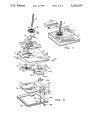
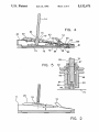
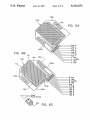
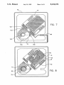
1
5,132,671
2
INTEGRATING GRAPHICS INPUT DEVICE
device, gross and ?ne control of cursor position were
generated, respectively, by a moveable cover and a
moveable puck contained within the cover.
BACKGROUND OF THE INVENTION
The invention relates to graphics input devices which
are operated manually by a user to provide signals de
SUMMARY OF THE INVENTION
The invention is an apparatus for use in a graphics
?ning a graphical object whose image is to be displayed
processing system in which a graphics processor re
in a graphics system.
sponds to graphics input signals descriptive of a graph
In the prior art, hand-operated pointing or picking
devices are known. These devices are operated by a
user to position a cursor on the screen of a graphical
output device such as a display. The primary role of
these devices is to permit a user to select a speci?c XY
location on a display screen. Other devices, called loca~
ics object by operating a graphics output device to
display an image of the object. The apparatus provides
to the graphics processor graphics input signals descrip
tive of the graphics object. The apparatus includes a
manually operable ?nger grip assembly with a ?rst
pressure sensor for providing pressure-generated, force
tor devices, include the tablet, the mouse, the trackball,
vector signals representing a display location on the
and the joystick. All of these devices are employed to
graphics
output device. A pressure-responsive lockout
move a screen cursor, and operate in combination with
switch
assembly
generates a lockout' signal. The lockout
separate devices which input information relevant to
signal is for indicating inactivation of the force vector
the location occupied by the cursor. Most commonly,
function buttons, function switches, or alpha-numeric 20 signals. In the apparatus, a stylus assembly is moveable
in two dimensions and has a position sensor for generat
keyboards are used for command or information entry
after positioning of a cursor.
ing graphics input signals representing a multi-dimen
In the prior art, the drawing of graphic objects has
sional portion of a graphics object which is to be dis
played at the indicated display location. An interface is
been the province of a program entered into a graphics
processor. Commonly, such an application program 25 connected to the ?nger grip assembly, to the lockout
utilizes a bottom-up procedure for object creation,
using hierarchially-arranged object components. The
switch assembly, and to the stylus assembly for receiv
ing the force vector signals, the lockout signal and the
graphics input signals. Last, a processor communicator
components map to a set of output primitives with mas
ter coordinates which are used to control the function
connected to the interface means communicates to the
30
of an output device, such as a display.
graphics processor display location signals representing
Free-hand creation of graphical objects by a user
currently is supported by complicated devices having
large drawing surfaces upon which the user moves a
stylus or pen to draw an image. The drawing surface is
related to the display surface by a dedicated applica
tions process which maps the drawing surface to the
display area. When the drawing is being made on the
drawing surface, a conversion function is invoked, dis
patching the application program, and converting the
drawing into an image which is displayed on the screen
of the display device.
The invention has the objective of providing a user
with a graphics input device which permits the display
an updated position for the location in response to the
force vector signals received by the interface, the lock
out signal, and graphic input signals representing the
graphic object to be displayed in the updated position.
The principal object of this invention is to provide a
graphics input device which integrates graphics input
position information and graphics object information
which is to be input at the indicated position.
It is the further object of this invention to provide
repositioning control of a position area displayed by a
graphics processor.
A further objective is to also provide graphics object
device of a graphics processing system to be used like a
input signals de?ning a portion of an image which is to
drawing surface, without the need to provide a physical 45 be displayed in the position area.
surface as an analog to the display surface. This permits
Other objectives and attendant advantages of this
a graphics processor system to provide to a user imme
invention will become manifest when the following
diate feedback, or echoing, of a drawing operation
detailed description is read with reference to the below
which the user is conducting. Thus, the display screen
described drawings.
of a CRT may be used much as a blank tablet upon 50
BRIEF DESCRIPTION OF THE DRAWINGS
which a user can draw.
The integrating graphics input device which has been
invented by the applicants provides hand-to-eye feed
back through a graphics processor system by combining
cursor-like movement of a position area on a display 55
surface, together with tablet-like entry of graphical
image information by means of a stylus which can be
manipulated by the user to draw within the located
positioned area. The device can be used to enter a con
tinuous image by successively relocating the position
area in a sequence of overlapping positions within
which the user's manual input is integrated to form a
continuous, coherent image.
The closest prior art to this device is the inventor's
FIG. 1 is an isometric perspective view of the inte
grating graphics input device.
FIG. 2 is a side-view of the device illustrated in FIG.
1.
FIG. 3 is an exploded assembly diagram of the device
of FIG. 1.
FIG. 4 is an elevational side sectional view of the
device of FIG. 1, the view being taken along line 175 of
FIG. 3.
FIG. 5 is a magni?ed, side sectional view of a stylus
slider in the device of FIG. 1.
FIGS. 6A, 6B, and 6C illustrate the sensors used to
integrating pointing device, described in US. Pat. No. 65 provide graphics object force vector, and lockout sig
nals in the device of FIG. 1.
4,719,455 which is incorporated herein by reference. In
that device, graphical input was provided by a hand
FIG. 7 is a top plan view illustrating a circuit board
manipulated device which ?t to the user's hand. In the
included in the assembly of the device of FIG. 1.