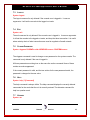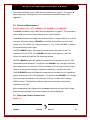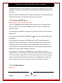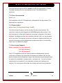
1
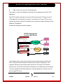
DT-6XXX
LOOP TEST NETWORKING
IP-LTCN APPLICATION
USER'S MANUAL
RELEASE 14 VERSION 1
BUILD 14.1
721 Route 202-206
Bridgewater, NJ 08807
fax: 908.218.1736
phone: 908.218.0500
email: [email protected]
http://www.datatekcorp.com
DT-6xxx IP-LTCN Application User's Manual
CONTENTS
1
FORWARD ......................................................................................................................................... 4
2
GLOSSARY......................................................................................................................................... 5
3
SUGGESTED REFERENCE............................................................................................................. 7
4
THE IP-LTCN MIGRATION SOLUTION ..................................................................................... 8
5
REDUNDANCY & RELIABILITY ISSUES ................................................................................. 10
6
IP-LTCN INTERFACES ................................................................................................................. 11
7
IP-LTCN APPLICATION COMMAND SET................................................................................ 14
7.1
INPUT CONVENTIONS ...................................................................................................................... 14
7.2
LOGIN ............................................................................................................................................. 14
7.3
LOGOUT .......................................................................................................................................... 15
7.4
EXIT ................................................................................................................................................ 15
7.5
CHANGE PASSWORD ....................................................................................................................... 15
7.6
HELP ............................................................................................................................................... 15
7.7
VERSION ......................................................................................................................................... 15
7.8
DISPLAY OF MEASUREMENTS ......................................................................................................... 16
7.9
DISPLAYING CURRENT CONNECTIONS ............................................................................................ 16
7.10
SNOOPING ON BX.25 TRAFFIC ................................................................................................... 17
7.11
CLEAR MEASUREMENTS ............................................................................................................ 17
7.12
VERIFY CONFIGURATION ........................................................................................................... 18
7.13
PROMPT LABELS ........................................................................................................................ 18
7.14
APPLICATION COMMENTS .......................................................................................................... 18
8
IP-LTCN MEASUREMENTS ......................................................................................................... 19
9
THE INSTALLATION COOKBOOK ........................................................................................... 20
10
KNOWLEDGE BASE ...................................................................................................................... 22
11
12
10.1
SPECIFIC MODEM INFORMATION ................................................................................................ 22
10.2
CABLING, ADAPTERS, AND PATCH PANELS ............................................................................... 22
10.3
ISOCHRONOUS LTS CONNECTIONS ............................................................................................ 22
INTERFACE DEFINITION ............................................................................................................ 23
11.1
CONTROL INTERFACE ................................................................................................................. 23
11.2
HOST INTERFACE ....................................................................................................................... 23
11.3
LTS INTERFACE ........................................................................................................................ 23
TAIL CIRCUITS .............................................................................................................................. 25
12.1
03/05/04
OPTION 1 – MAKE THE LTS/DCTU IP NETWORK CAPABLE ..................................................... 25
Datatek Applications Inc.
2
DT-6xxx IP-LTCN Application User's Manual
12.2
OPTION 2 – USE A MODEM TAIL CIRCUIT .................................................................................. 26
12.3
OPTION 3 – USE A MEDIATION DEVICE IN THE CENTRAL OFFICE .............................................. 27
12.4
OPTION 4 – USING AN EXISTING DATAKIT NETWORK................................................................ 28
12.5
WHAT NOT TO DO WITH TAIL CIRCUITS .................................................................................. 29
13
HARDWARE WARRANTY............................................................................................................ 31
14
END-USER LICENSE AGREEMENT FOR SOFTWARE.......................................................... 31
15
14.1
SOFTWARE LICENSE ................................................................................................................... 31
14.2
INTELLECTUAL PROPERTY RIGHTS ............................................................................................. 31
14.3
SOFTWARE SUPPORT .................................................................................................................. 31
14.4
EXPORT RESTRICTIONS .............................................................................................................. 31
14.5
LIMITED WARRANTY ................................................................................................................. 32
14.6
NO OTHER WARRANTIES ........................................................................................................... 32
14.7
SPECIAL PROVISIONS.................................................................................................................. 32
LIMITATION OF LIABILITY....................................................................................................... 32
03/05/04
Datatek Applications Inc.
3
DT-6xxx IP-LTCN Application User's Manual
1
FORWARD
The Mechanized Loop Test operations system has been around since what can seem
like the dawn of time. It provides a necessary testing function in the maintenance of end
user loop facilities. The Mechanized Loop Test operations system has been continually
updated to support an ‘up to date’ set of loop elements.
The communications between the Mechanized Loop Test operations system contain
components that have become manufacturer discontinued. As such, the
communications path between the Mechanized Loop Test operations system and the
loop test equipment is at risk.
The IP-LTCN application will be described as a replacement for all existing
communications environments.
The IP-LTCN application is an Internet Protocol replacement that has been designed to
be used in conjunction with the Tollgrade LoopCare product. Support and feature
request issues should be addressed directly to the author of this document.
03/05/04
Datatek Applications Inc.
4
DT-6xxx IP-LTCN Application User's Manual
2
GLOSSARY
BNS
Broadband Networking System
BX.25
Bell System X.25 Protocol Specification.
CO
Central Office
CODEC
Coder/Decoder
COLO
Central Office Co-Location
DCN
Loop Test System Data Communications Network
DCTU
Directly Connected Test Unit
DK
Datakit
DMN
Digital Measurement Node
DMU
Digital Measurement Unit
IP
Internet Protocol
LCN
Loop Test System Communications Network
LMOS
Loop Maintenance Operations System
LoopCare
The new name for the Mechanized Loop Test Operations
System.
LTCN
Loop Test System TCP/IP Communications Network
LTS
Loop Test System
MLT
Mechanized Loop Test Operations System
NE
Network Element
OS
Operations System
OSS
Operations Support System
RFC
Request For Comments (Internet Specifications)
SNMP
Simple Network Management Protocol
03/05/04
Datatek Applications Inc.
5
DT-6xxx IP-LTCN Application User's Manual
TCP
Transport Control Protocol
TCP/IP
Transport Control Protocol over the Internet Protocol
UMI
Universal Mediation Interface (Datakit/BNS interface module)
URP
Universal Receiver Protocol
03/05/04
Datatek Applications Inc.
6
DT-6xxx IP-LTCN Application User's Manual
3
SUGGESTED REFERENCE
The following documents are resident at http://www.datatekcorp.com under the
documentation button.
Document
Scope
DT-6xxx Platform User’s Manual.
Describes the DT-6xxx Embedded
Network Processor infrastructure and
command set. This includes configuration
information, hardware specifications, and
SNMP MIB support.
The DT-6xxx is the infrastructure on which
the Mechanized Loop Test
communications applications reside.
DT-4000 User’s Manual.
Describes the DT-4000 multi-protocol
access device. The DT-4000 implements
special functions enabled by the IP-LTCN
to interface with LTS and DCTU interfaces.
DT-4180 User’s Manual
Describes the DT-4180 access device. The
DT-4180 implements special functions
enabled by the IP-LTCN to interface with
LTS and DCTU interfaces.
DT-4216, DT-4232, DT-4280
Describes the DT-42xx series of access
devices. The DT-42xx implements the
User’s Manual
special functions enabled by the IP-LTCN
to interface with LTS and DCTU interfaces.
03/05/04
DT-6xxx Redundant Operation
Describes the method of operating the DT-
White Paper.
6xxx in a 1+1 sparing configuration.
Datatek Applications Inc.
7
DT-6xxx IP-LTCN Application User's Manual
4
THE IP-LTCN MIGRATION SOLUTION
The IP-LTCN application is a migration solution for all variants of the Loop Test
Communications Environments. It is designed to be used in conjunction with an Internet
Protocol conversion of the Tollgrade LoopCare product. The LoopCare product is the
evolution of the Lucent Technologies MLT operations system.
The IP-LTCN can replace a DCN in its entirety. This eliminates a maintenance risk since
the DCN is manufacturer discontinued, with a consequential shortage of spare parts. A
side benefit is that the IP-LTCN will free up the 120 square feet of conditioned floor
space taken up by the DCN.
The IP-LTCN supports an enhanced TCP/IP interface to the LoopCare host. This allows
connectivity with the LoopCare hosts using an IP infrastructure. The new LoopCare
hosts do not have either a BX.25 interface to communicate with a DCN, nor a fiber
interface to communicate with a BNS node. Instead, the LoopCare hosts have
implemented a direct TCP/IP interface to the IP-LTCN application.
The following diagram shows this arrangement:
IP-LTCN Deployment
TCP/IP Hosts
DT-6xxx
IP-LTCN Application
LoopCare
IP
Network
LoopCare
Central Office
LTSs
DT-4xxx
DT-4xxx
BX.25
Central Office
LTSs
Private
Lines
Async
DMUs
BX.25
Async
BX.25
DMUs
DCTUs
03/05/04
5ESS
DCTUs
Datatek Applications Inc.
5ESS
8
DT-6xxx IP-LTCN Application User's Manual
In the diagram above, the asynchronous DMUs would be accessed directly by the
LoopCare OS host. The LoopCare OS host would establish a TCP connection with the
DT-4xxx port to which the DMU is attached. Data exchange would proceed using RFC
854 encapsulation as normal.
The LTS connections (and DCTU connections via the 5ESS) would be exactly the same
as in the LCN or DCN cases. That is, the LTS link is connected to the DT-4xxx port. The
DT-4xxx port is configured to originate a TCP connection to the IP-LTCN at the TCP port
number corresponding to the LTS identification.
The OS host connections to the IP-LTCN are done directly using TCP/IP. This is done at
the designated TCP port number for this type of interface. See the interface section of
this document for more details. The host protocol suite is fully supported. Status
information of the LTS connections will be available if the MLT OS host desires.
03/05/04
Datatek Applications Inc.
9
DT-6xxx IP-LTCN Application User's Manual
5
REDUNDANCY & RELIABILITY ISSUES
The Loop Test operation requires a very high reliability. Each solution provides some
form of protection. However, the IP-LTCN is superior in all regards.
The DCN approach to this type of reliability was in having the ability of multiple “A”
cabinets access an LTS on a single “B” cabinet. The MLT host would then be attached
to two “A” cabinets. If a BX.25 link from the host to the “A” cabinet would fail, test
operations would proceed on the alternate connection. If an “A” cabinet would fail, the
alternate “A” cabinet would still be attached to the host and could proceed with the test
operations. However, if a “B” cabinet should fail; then all the LTS connections would not
be protected. An engineer would need to re-cable the LTS links to another “B” cabinet
manually.
The LCN approach to this type of reliability was hinged on the DKAP making the
outbound calls to the SAM endpoints on the BNS network. Should the DKAP fail, then all
connections would be torn down. A new DKAP would then be brought into service
manually. The MLT host would then reconfigure the DKAP and establish new calls to the
LTS endpoints on the SAM. Note that this is a manual operation since the address
groups for the DKAP to which the MLT OS hosts make the call need to be unique to a
single DKAP channel sets. Consequently, they cannot be pooled reliably. Consult the
BNS documentation for more information.
The IP-LTCN application relies on the DT-6xxx redundancy infrastructure for its
reliability. The DT-6xxx infrastructure provides 100% reliability through a 1+1 spare
arrangement. Should a DT-6xxx fail, the spare would immediately take over
automatically. The spare would become the active DT-6xxx in the set, and assume the
public IP address of the set. It should be noted that the application interfaces do not
need to change, or even be made aware, of the duplex nature of the DT-6xxx
redundancy. The IP-LTCN implements both the “A” and “B” cabinets of the DCN, and all
interface paths of the LCN. Consequently, the IP-LTCN is the most reliable solution
possible for the loop test environment. Consult the DT-6xxx redundancy documentation
for more information. Redundancy is optional. It is not required by the IP-LTCN
application.
03/05/04
Datatek Applications Inc.
10
DT-6xxx IP-LTCN Application User's Manual
6
IP-LTCN INTERFACES
The TCP port numbers associated with a DT-6xxx application are normally referenced
by which instance the application is installed. The IP-LTCN is different in that premise
because of the large number of distinct TCP port numbers, the need to simplify
administration, and engineering configurations.
The IP-LTCN application may only be installed on instance #1 of the DT-6xxx. Installing
on any other instance will result in a periodic alarm after which the IP-LTCN will proceed
to sleep perpetually. Consult the DT-6xxx infrastructure manual for information on how to
install an application.
The TCP Numbers associated with the IP-LTCN application (using instance #1 as
required) are as follows:
Set
#Channels
TCP Port#
Usage
OA&M
1
10001
Configuration and administration of the
IP-LTCN application. This is the
standard configuration TCP port
number for instance #1. The general
formula is 10,000 + instance#.
Connections to this TCP port are made
via a Telnet client.
Host
20
30001 - 30020
These are the host data port
connections. They are maintained as
separate TCP port numbers so that
every LoopCare OS host may be
configured uniquely. In that manner,
access is always guaranteed for a
particular host.
03/05/04
Datatek Applications Inc.
11
DT-6xxx IP-LTCN Application User's Manual
Control
20
31001 - 31020
Each of these TCP ports reports status,
and provides a mechanized control
interface to a host. This interface is
documented as an appendix to this
document. All of the control connections
are equivalent. They are maintained as
separate TCP ports so that each one
may be configured uniquely.
LTS
768
40000 + LTS ID
There are a total of 768 TCP ports
reserved for LTS connections. These
are from 40,001 through 40,768 and
correspond to LTS ID 1 through 768
inclusive. This is identical to a physical
mapping on a DCN “B” cabinet. BX.25
from the LTS connections are
terminated by the IP-LTCN on these
connections.
An example of how these circuits are used follows:
The IP-LTCN would be assigned to instance #1 on the DT-6xxx. Once done, the IPLTCN will listen for inbound TCP connections on all of the TCP port numbers specified
above.
Each DT-4xxx port on which an LTS is connected then originates a TCP call to the IPLTCN application at its LTS identification TCP port number (40,001 to 40,768). The IPLTCN will then establish and terminate the BX.25 protocol to the LTS on these
connections.
03/05/04
Datatek Applications Inc.
12
DT-6xxx IP-LTCN Application User's Manual
A TCP/IP LoopCare OS host responsible for control functions, including address upload,
would attach any of the TCP port numbers between 31,001 and 31,020. This connection
is optional, and not required for the proper operation of the IP-LTCN.
Any TCP/IP LoopCare OS host may also make a connection to the IP-LTCN at TCP port
numbers 30,001 to 30,020.
No correspondence exists between the TCP ports used for host interfaces, and the TCP
ports used for control interfaces. All control interfaces are equivalent to each other. All
host interfaces are equivalent to each other. The multitude of each type is to allow for
simultaneous access for different hosts.
Once both the LoopCare OS host and LTS endpoints have established connections; the
IP-LTCN can emulate the DCN/LCN functions as needed.
03/05/04
Datatek Applications Inc.
13
DT-6xxx IP-LTCN Application User's Manual
7
7.1
IP-LTCN APPLICATION COMMAND SET
INPUT CONVENTIONS
All parameters may be given on the command line. Parameters of the form
name=<value> may be given in any order.
For several complex commands, listed below, missing parameters, or corrections of
errors in given parameters, of the form name=<value> are collected by prompting the
console user. The user responds to a prompt for the name by typing the required
<value> followed by newline. Defaults are supplied in some cases, so the user need
only enter newline.
Commands may be entered in upper or lower case.
Parameters of the form name=value may use upper or lower case for name.
Default values, if any, are shown in parenthesis as part of the prompt.
Case is not preserved for values.
Backspace erases one character.
7.2
LOGIN
Syntax: login PASSWD=<password>
The login command is used to allow access to the other configuration commands.
The login command is only visible when the application is in the logged out (i.e. secure)
mode. The unit enters this mode whenever a logout command is issued or when the
Telnet to the application instance OA&M TCP port is interrupted for any reason.
The password is not echo-suppressed. The password consists of up to seven
alphanumeric characters. Special characters are not allowed.
The default password is “initial”. If no password is given, the IP-LTCN will prompt for a
password. In the prompted mode, the password is not echoed. Instead an asterisk is
echoed for each character.
03/05/04
Datatek Applications Inc.
14
DT-6xxx IP-LTCN Application User's Manual
7.3
LOGOUT
Syntax: logout
The logout command is only allowed if the console user is logged in. It uses no
arguments. It will set the console to the logged out mode.
7.4
EXIT
Syntax: exit
The exit command is only allowed if the console user is logged in. It uses no arguments.
It will set the console to the logged out mode, and drop the telnet connection. It is useful
where a daisy chain of telnet connections are used to negotiate a firewall network.
7.5
CHANGE PASSWORD
Syntax: chgpass PASSWD=<old> NEWPASS=<new> CONFIRM=<new>
The chgpass command is used to change a user password on the system console. The
command is only allowed if the user is logged in.
All three parameters must be given on the same line as the command. None of those
entries are echo-suppressed.
If the current password is valid, and the two entries for the new password match, the
password is changed to the new value.
7.6
HELP
Syntax: help |? [Command]
The help command is always visible. The help command displays the currently allowed
commands for the mode that the unit is currently entered. The alternate command for
help is a question mark.
7.7
VERSION
Syntax: ver
03/05/04
Datatek Applications Inc.
15
DT-6xxx IP-LTCN Application User's Manual
The version command is only visible when the application is logged in. The command
has no arguments. It displays the current software and database revisions of the
application.
.
7.8
DISPLAY OF MEASUREMENTS
Syntax: dmeas [ ALL | CTL <RANGE> | OS <RANGE> | LTS <RANGE>
The dmeas command is only visible when the application is logged in. The command is
used to display the current measurements on any of the interfaces.
The dmeas command may display the measurements for a single interface, or all of the
interfaces. Where the value of <RANGE> is specified, the identifier may be a single
numeric (e.g. the number ‘3’), a numeric range (e.g. ‘1-3’), or the value ‘ALL’ to indicate
the entire allowed numeric range.
The LTS <RANGE> option will display the measurement information for the LTS
connection to the IP-LTCN. The <RANGE> may have values between 1 and 768
inclusive to match the LoopCare OS numbering scheme.
The CTL <RANGE> option will display the measurement information for the IP-LTCN
mechanized control interfaces. The values in the <RANGE> are 1 through 20 inclusive
that correspond one for one to the TCP port numbers 31,001 through 31,020 inclusive.
There is no requirement that these interfaces be attached in any particular order.
The OS <RANGE> option will display the measurement information for the Operations
System interface to the IP-LTCN application. The values in the <RANGE> are 1 through
20 inclusive that correspond one for one to the TCP port numbers 30,001 through
30,020 inclusive. The Operations System hosts are not required to attach these
interfaces in any order.
When measurements are displayed via the dmeas command, and more than a single
entity has been specified; only non-zero entries are actually displayed.
7.9
DISPLAYING CURRENT CONNECTIONS
Syntax: dc
03/05/04
Datatek Applications Inc.
16
DT-6xxx IP-LTCN Application User's Manual
The dconn command is used to display all of the current connections into the IP-LTCN
application. This includes all of the LTS, Control Interface, and Operations System native
connections.
Please note that the command does not require any arguments. The command will issue
a report that shows the connection peer for each active connection.
7.10 SNOOPING ON BX.25 TRAFFIC
Syntax: snoop [ OFF | OS <#> | LTS <#> ]
The IP-LTCN application has a diagnostic ability to snoop on any of interfaces which
carry user data. This is done with the snoop command. All output is directed to the
OA&M connection.
If the command is invoked with no arguments, it produces a report of all active snooper
configurations.
If the command is invoked with the OFF option, all of the active snooper configurations
are disabled.
If the command is invoked with the LTS <#> option, the LTS interface specified is
snooped. The <#> is in the range of 1 to 768 to be compatible with the LoopCare OS
numbering scheme. Output is displayed on the OA&M session. Please note that this
could be extensive for a moderately busy BX.25 line. Both BX.25 and session data are
displayed. The session data messages are decoded.
If the command is invoked with the OS <#> option, the OS interface specified is
snooped. The <#> is in the range of 1 to 20 inclusive and correspond to host interfaces
on TCP ports 30,001 through 30,020. The OS interface does not have a BX.25 protocol
present, but frame data is decoded and displayed on the OA&M session. Please note
that this could become rather voluminous for even a lightly loaded OS interface.
7.11 CLEAR MEASUREMENTS
Syntax: clr
03/05/04
Datatek Applications Inc.
17
DT-6xxx IP-LTCN Application User's Manual
The measurements displayed with the dmeas command are aggregated until cleared.
The clear command will set all measurements to zero. The command has no
arguments.
7.12 VERIFY CONFIGURATION
Syntax: vfy
The configuration of the IP-LTCN application is displayed with the vfy command. The
command has no arguments.
7.13 PROMPT LABELS
Syntax: label [ “Double Quoted String” | NONE ]
The label command is used to give the command console a unique prompt. The
command is visible only when logged into the IP-LTCN administrative console. If the
label command is invoked without arguments, the current configuration of the label is
displayed. If the argument to the label command is the word ‘none’, any current label is
set to a null value. If the argument to the label command is a double quoted string, the
contents of the string becomes the application console prompt label. A console label
may be up to 31 characters in length.
7.14 APPLICATION COMMENTS
Syntax: comment [ L1=”Any Comment”]
[ L2=”Any Comment”]
[ L3=”Any Comment”]
The IP-LTCN application may have comments which are displayed with the verify
configuration command. Up to three lines of comments are available. Each line may
have a comment up to 64 characters in length. Each comment is double quoted to allow
for spaces to be embedded. A comment with no characters (i.e. “”) is used to delete a
comment which is not desired. It is not necessary to delete prior to adding a new
comment. The new comment shall replace the existing comment at the line specified.
03/05/04
Datatek Applications Inc.
18
DT-6xxx IP-LTCN Application User's Manual
8
IP-LTCN MEASUREMENTS
This section itemizes the measurements available using the display measurements
(dmeas) command.
The base measurements are always displayed, and the error and exception counters are
only displayed if nonzero.
The BX.25 measurements available are as follows:
Measurement Description
Type
Number of LAPB Frames Received
Base
Number of LAPB Frames Transmitted
Base
Number of LAPB Bytes Received
Base
Number of LAPB Bytes Transmitted
Base
Number of Invalid Frames Received.
Exception
Number of Frames Ignored when Link is not Inactive.
Exception
03/05/04
Datatek Applications Inc.
19
DT-6xxx IP-LTCN Application User's Manual
9
THE INSTALLATION COOKBOOK
This section is a series of installation instructions for the deployment of the IP-LTCN
application.
The TCP/IP capable LoopCare host uses the OS native protocol TCP ports on the IPLTCN application to make their connection. A connection to a Control TCP port is not
required, but may be used by the LoopCare host to acquire link status information for the
attached LTS endpoints.
Consider the following connectivity diagram:
TCP/IP Deployment
Co-Location NOT Required
DT-6xxx
IP-LTCN Application
10/100 BaseT
LoopCare
IP
IP
IP WAN
IP
10/100 BaseT
BX.25
BX.25
Any
Network
LoopCare
LTS
Or
DT-4xxx
Direct Connection
LTS
BX.25
In the diagram above, none of the components are required to be located with each
other. The communications between components is via the IP infrastructure. The
LoopCare OS hosts communicate directly with the IP-LTCN using TCP/IP and the
protocol suite. It should be noted that this configuration is exceptionally economical both
in terms of equipment and facility expenses. A typical deployment would have one DT6xxx and eight DT-4xxxs.
03/05/04
Datatek Applications Inc.
20
DT-6xxx IP-LTCN Application User's Manual
Given the above, the deployment could be as follows:
1. Install each DT-6xxx by assigning an IP address, gateway address (if any), and the
IP-LTCN application on instance #1. These are done by the ipaddr <ip_address>,
the gateway <ip_address>, and the app 1 type=ip_ltcn commands on the DT-6xxx
system console. It will be necessary to reboot the DT-6xxx following the IP address
configuration. This step may be staged in advance of the deployment.
2. Configure the DT-4xxx ports so that they initiate a TCP call to the IP-LTCN
application at the TCP port appropriate for its function. The following assumes
external clocking via a modem set such as a 202T.
Port <#> type=ORIG Dest=<DT-6xxx IP Address> dport=<40000+LTS#>
Port <#> prot=HDLC pap=ON dxe=DTE clk=norm enc=nrz
Rs <#>
The cable adapter is a SYNC DTE with a DB-25 Male. This attaches to the cable of
the 202T modem to the Network Element. The <40000+LTS#> is for LTS ports in
this configuration. The OS connections are native TCP/IP. That is, the LTS port picks
a unique TCP number associated with its LTS identifier. For an LTS identifier of 333,
the TCP port is 40333 or 40000 + the LTS identification. The <#> is the DT-4xxx port
number being configured. Since the “permanently active” option is configured, the
TCP call will be immediately set up. Doing a “display connections” command (dc) on
either the DT-4xxx or the IP-LTCN OA&M session will show the LTS connection at
this time. The clock option normally defaults to ‘normal’ operation, and the encoding
normally defaults to NRZ. However, making the specification is not harmful.
3. No further configuration is required.
03/05/04
Datatek Applications Inc.
21
DT-6xxx IP-LTCN Application User's Manual
10
KNOWLEDGE BASE
This section is a random collection of information that may be relevant during the
deployment of the IP-LTCN application. In order to avoid duplication and potential for
error, much of the information in this section has been moved to their respective User’s
Manuals.
10.1 SPECIFIC MODEM INFORMATION
Information about the configuration of specific modem sets are now exclusively covered
in the DT-4000 User’s Manual, the DT-42xx User’s Manual, and the DT-4180 User’s
manual. In the Build #20 version of the DT-4000 User’s Manual, it is on page 58 under
section 15 “Cabling”. In the Build #3 version of the DT-4180 User’s Manual, it is on page
50 and section 14.
10.2 CABLING, ADAPTERS, AND PATCH PANELS
Consult the DT-4000 User’s manual for Build #20 or higher, the DT-42xx User’s manual
Build #1.0 or higher, or the DT-4180 User’s manual Build #3 or higher. These manuals
cover the DT-9116 Intelligent Patch Panel, and the various wiring adapters.
10.3 ISOCHRONOUS LTS CONNECTIONS
This section is covered in the appropriate DT-4xxx User’s manual under the heading
“Synchronous Protocols with Recovered Clocks”. In the DT-4000 build #20 manual, this
is section 16 on page 67. A similar section is covered in the DT-4180 User’s manual.
03/05/04
Datatek Applications Inc.
22
DT-6xxx IP-LTCN Application User's Manual
11
INTERFACE DEFINITION
The intent of this section is to define the interfaces used by the IP-LTCN application for
reference during troubleshooting activity in the field. The interfaces may be monitored
both within the IP-LTCN application, and by external means such as a LAN sniffer or a
serial line protocol analyzer on the DT-4xxx port.
The interfaces are partitioned by the TCP port on which they interface. There are three
types of interfaces. These are the IP-LTCN control interface, a TCP/IP host interface,
and a BX.25 LTS interface.
11.1 CONTROL INTERFACE
The control interfaces to the IP-LTCN accept a connection on TCP ports 31,001 through
31,020 inclusive. Each of the control interfaces are equivalent to each other. The intent
of the interface is to provide a mechanized means for a host to acquire information about
the operation of the IP-LTCN application. Configuration of the IP-LTCN application is not
performed on the control interface.
11.2 HOST INTERFACE
The host interface to the IP-LTCN accepts a connection at TCP port between 30,001
and 30020 inclusive. Each TCP port has a hunt group of exactly one. They are
maintained unique to prevent a rogue host from locking out its partner.
The host interface provides the means by which messages may be sent to an LTS and
responses directed to the originating host. Spurious messages from an LTS are sent to
all connected hosts simultaneously. Duplication of spurious messages is prevented by
the IP-LTCN.
11.3 LTS INTERFACE
The LTS interface to the IP-LTCN accepts a connection at TCP port between 40,001
and 40,768 inclusive. Each TCP port has a hunt group of exactly one. They are
maintained unique to provide an exact mapping to a particular LTS. Exactly one DT-4xxx
(e.g. DT-4000, DT-4180, DT-4216, DT-4232, DT-4280) port may make a connection to
03/05/04
Datatek Applications Inc.
23
DT-6xxx IP-LTCN Application User's Manual
an IP-LTCN TCP port for a particular LTS ID. The DT-4xxx provides “B” cabinet
functions for the IP-LTCN.
03/05/04
Datatek Applications Inc.
24
DT-6xxx IP-LTCN Application User's Manual
12
TAIL CIRCUITS
The IP-LTCN has several deployment options. Many RBOCs will chose to implement a
“DCN Drop-In” where the IP-LTCN is dropped in place of an existing DCN. When this
occurs, a “tail circuit” will exist for some period of time. This section details the tail circuit
deployment. Because of the unique nature of the LTS and DCTU endpoints; special care
must be used in the selection of the tail circuit transport.
In the sections below, several options for tail circuits are presented. Any of these can be
used interchangeably. In addition, an improper scenario is presented. This last incorrect
scenario is certain to present a failure situation because of timing issues. Consequently,
it is specifically not supported by the IP-LTCN.
12.1 OPTION 1 – MAKE THE LTS/DCTU IP NETWORK CAPABLE
This option is simply where the LTS or DCTU is made IP network capable. This is done
with a DT-9480 network adapter. A connectivity diagram of this solution is as follows:
IP-LTCN Deployment
Direct LTS/DCTU to IP
using DT-9480
DT-6xxx
IP-LTCN Application
LoopCare
IP
Network
LoopCare
Central Office
Central Office
IP
Network
LTSs
IP
Network
IP
LTSs
IP
IP
IP
DMUs
DMUs
DCTUs
5ESS
5ESS
DCTUs
When the LTS or DCTU is made IP network capable with a DT-9480 adapter, there is no
mediation equipment of any kind required. It is an easy and clean method of eliminating
the tail circuit.
03/05/04
Datatek Applications Inc.
25
DT-6xxx IP-LTCN Application User's Manual
12.2 OPTION 2 – USE A MODEM TAIL CIRCUIT
This option is really nothing more than the status quo after the DCN has been initially
replaced. The DT-4xxx mediates to a BX.25 connection. These are then distributed by
modem tail circuits to the LTS or DCTU.
IP-LTCN Deployment
Modem Tail Circuits
DT-6xxx
IP-LTCN Application
LoopCare
IP
Network
LoopCare
DT-4xxx
Central Office
LTSs
Private
Lines
Async
DMUs
DCTUs
BX.25
5ESS
The diagram above has such a configuration. The DT-4xxx series works in conjunction
with the DT-6xxx IP-LTCN to handle the IP to BX.25 mediation in a manner suitable for
the LTS and/or DCTU. Since the modem circuits are constant latency, they can be
distributed remotely.
This option has on-going costs of maintaining the tail circuits; but is otherwise trouble
free.
03/05/04
Datatek Applications Inc.
26
DT-6xxx IP-LTCN Application User's Manual
12.3 OPTION 3 – USE A MEDIATION DEVICE IN THE CENTRAL OFFICE
One of the most common approaches is to distribute the DT-4xxx mediation devices to
the central offices. The DT-4xxx mediation devices support other systems such as SCC
connections and E2A telemetry and are shared with IP-LTCN usage. A diagram of that
deployment is as follows:
IP-LTCN Deployment
Distributed Mediation
DT-6xxx
IP-LTCN Application
LoopCare
IP
Network
LoopCare
Central Office
LTSs
DT-4xxx
BX.25
BX.25
Async
DMUs
DCTUs
5ESS
In the above diagram, it can be noted that any port may support one or any protocol.
Several operations systems can share a single mediation device and reduce the overall
cost of deployment considerably. The DT-4xxx mediation device insures the proper
timing and presentation of the interface to the LTS and DCTU using local (B)X.25 or
isochronous cabling at the Central Office.
03/05/04
Datatek Applications Inc.
27
DT-6xxx IP-LTCN Application User's Manual
12.4 OPTION 4 – USING AN EXISTING DATAKIT NETWORK
Another common approach is to use an existing Datakit network for distribution of the
LTS/DCTU circuits. This only works because the Datakit network is connection oriented
and has a constant latency. Consequently, the timing functions of the DT-4xxx LTCN
interface are preserved within the Datakit network. Typically, a SAM is used at either
endpoint. Consider the following diagram:
Tail Circuit Distribution Via Datakit/BNS
BNS-2000
DT-6xxx
w/ IP-LTCN
UTM
TCP/IP
BNS-2000
ANY SAM or DT-4000
Central Office
U T T T
T C E E
M O R R
N M M
3 3
2 2
T
E
R
M
3
2
T
E
R
M
3
2
BNS-2000
SAM Trunk
Any
SAM
DT-4xxx
DK RJ-Xover
cables
5ESS
DCTU
BX.25
BX.25
LTS
DMU
DT-4xxx
Notes: Isochronous operation is supported only by the DT-4xxx.
A UTM is the preferred BNS trunk in this deployment.
In the diagram above, the mediation occurs at the DT-4xxx interface. The BNS network
then transports the BX.25 preserving both the format and the timing. Isochronous
connections must be connected directly to a DT-4xxx device since the BNS network and
the SAM in particular cannot support that protocol.
03/05/04
Datatek Applications Inc.
28
DT-6xxx IP-LTCN Application User's Manual
12.5 WHAT NOT TO DO WITH TAIL CIRCUITS
As explained in the previous section, the distribution of LTS/DCTU connections does
work with the Datakit/BNS network. It does so because Datakit/BNS is a connection
oriented network with constant paths and constant delays. Both of these assumptions
are not true with an IP based network. There is considerable logic in the DT-4xxx to
account for the anomalies in the IP network between the DT-6xxx and the DT-4xxx. The
LTS and DCTU are not tolerant of these anomalies. Once the frames have been
transmitted by the DT-4xxx, there is no additional protection. Performing additional
transport of these frames with an IP network is certain to fail at some time. The failure
can and will lock the LTS so that it must be manually restarted. This is a known failure
mode that occurs even when DT-4xxx are used in the second hop.
Consider the following diagram of what not to do:
Tail Circuit Distribution - WRONG
DT-6xxx
w/ IP-LTCN
TCP/IP
TCP/IP
Central Office
Any IP Mediation
Device
DT-4xxx
BX.25
Any IP Mediation
Device
5ESS
DCTU
BX.25
BX.25
LTS
DMU
DT-4xxx
In the diagram above, the frames are transported across the IP WAN by the Mediation
device. However, timing is not preserved and packet loss can occur. Consequently, this
scenario will fail and is specifically not supported by the IP-LTCN. Note that even if the
03/05/04
Datatek Applications Inc.
29
DT-6xxx IP-LTCN Application User's Manual
IP mediation device were another DT-4xxx device, the logic to preserve the LTS/DCTU
integrity only operates between the IP-LTCN and the initial DT-4xxx. Consequently, even
that scenario will fail. It cannot be overly stressed that this deployment should be
avoided.
03/05/04
Datatek Applications Inc.
30
DT-6xxx IP-LTCN Application User's Manual
13
HARDWARE WARRANTY
The warranty period for the DT-6xxx hardware on which this application is resident shall be ninety
(90) days from the date of delivery of the hardware unless extended warranty coverage has been
purchased at additional charge without lapse in coverage. Replacements and repairs of the
hardware are guaranteed for the longer of the remaining original warranty period or thirty (30)
days.
14
END-USER LICENSE AGREEMENT FOR
SOFTWARE
This License Agreement ("License") is a legal contract between you and the manufacturer ("Manufacturer") of the system
("HARDWARE") with which you acquired software product(s) identified above ("SOFTWARE"). The SOFTWARE may
include printed materials that accompany the SOFTWARE. Any software provided along with the SOFTWARE that is
associated with a separate end-user license agreement is licensed to you under the terms of that license agreement. By
installing, copying, downloading, accessing or otherwise using the SOFTWARE, you agree to be bound by the terms of
this LICENSE. If you do not agree to the terms of this LICENSE, Manufacturer is unwilling to license the SOFTWARE to
you. In such event, you may not use or copy the SOFTWARE, and you should promptly contact Manufacturer for
instructions on return of the unused product(s) for a refund.
14.1 SOFTWARE LICENSE
You may only install and use one copy of the SOFTWARE on the HARDWARE (unless otherwise licensed by
Manufacturer). The SOFTWARE may not be installed, accessed, displayed, run, shared or used concurrently on or from
different computers, including a workstation, terminal or other digital electronic device (“Devices”). Notwithstanding the
foregoing and except as otherwise provided below, any number of Devices may access or otherwise utilize the services of
the SOFTWARE. You may not reverse engineer, decompile, or disassemble the SOFTWARE, except and only to the
extent that such activity is expressly permitted by applicable law notwithstanding this limitation. The SOFTWARE is
licensed as a single product. Its component parts may not be separated for use on more than one HARDWARE. The
SOFTWARE is licensed with the HARDWARE as a single integrated product. The SOFTWARE may only be used with the
HARDWARE as set forth in this LICENSE. You may not rent, lease or lend the SOFTWARE in any manner. You may
permanently transfer all of your rights under this LICENSE only as part of a permanent sale or transfer of the
HARDWARE, provided you retain no copies, you transfer all of the SOFTWARE (including all component parts, the media
and printed materials, any upgrades, this LICENSE and, if applicable, the Certificate(s) of Authenticity), and the recipient
agrees to the terms of this LICENSE. If the SOFTWARE is an upgrade, any transfer must also include all prior versions of
the SOFTWARE. Without prejudice to any other rights, Manufacturer may terminate this LICENSE if you fail to comply
with the terms and conditions of this LICENSE. In such event, you must destroy all copies of the SOFTWARE and all of
its component parts.
14.2 INTELLECTUAL PROPERTY RIGHTS
The SOFTWARE is licensed, not sold to you. The SOFTWARE is protected by copyright laws and international copyright
treaties, as well as other intellectual property laws and treaties. You may not copy the printed materials accompanying the
SOFTWARE. All title and intellectual property rights in and to the content which may be accessed through use of the
SOFTWARE is the property of the respective content owner and may be protected by applicable copyright or other
intellectual property laws and treaties. This LICENSE grants you no rights to use such content. All rights not expressly
granted under this LICENSE are reserved Manufacturer and its licensors (if any).
14.3 SOFTWARE SUPPORT
SOFTWARE support is not provided by Manufacturer, or its affiliates or subsidiaries separate from the HARDWARE. For
SOFTWARE support, please contact your supplier of the HARDWARE. Should you have any questions concerning this
LICENSE, or if you desire to contact Manufacturer for any other reason, please refer to the address provided in the
documentation for the HARDWARE.
14.4 EXPORT RESTRICTIONS
You agree that you will not export or re-export the SOFTWARE to any country, person, or entity subject to U.S. export
restrictions. You specifically agree not to export or re-export the SOFTWARE: (i) to any country to which the U.S. has
embargoed or restricted the export of goods or services, which as of March 1998 include, but are not necessarily limited
to Cuba, Iran, Iraq, Libya, North Korea, Sudan and Syria, or to any national of any such country, wherever located, who
intends to transmit or transport the products back to such country; (ii) to any person or entity who you know or have
reason to know will utilize the SOFTWARE or portion thereof in the design, development or production of nuclear,
chemical or biological weapons; or (iii) to any person or entity who has been prohibited from participating in U.S. export
transactions by any federal agency of the U.S. government.
03/05/04
Datatek Applications Inc.
31
DT-6xxx IP-LTCN Application User's Manual
14.5 LIMITED WARRANTY
Manufacturer warrants that (a) the SOFTWARE will perform substantially in accordance with the accompanying written
materials for a period of ninety (90) days from the date of shipment. Software support is limited to the hours of 8 AM to 5
PM ET Monday through Friday excluding Datatek observed holidays. Other coverage and extended warranty may be
purchased at an additional charge. Any implied warranties on the SOFTWARE are limited to ninety (90) days. Some
states/jurisdictions do not allow limitations on duration of an implied warranty, so the above limitation may not apply to
you.
Manufacturer's and its suppliers' entire liability and your exclusive remedy shall be, at Manufacturer's option, either (a)
return of the price paid, or (b) repair or replacement of the SOFTWARE that does not meet this Limited Warranty and
which is returned to Manufacturer with a copy of your receipt. This Limited Warranty is void if failure of the SOFTWARE
has resulted from accident, abuse, or misapplication. Any replacement SOFTWARE will be warranted for the remainder of
the original warranty period or thirty (30) days, whichever is longer.
14.6 NO OTHER WARRANTIES
TO THE MAXIMUM EXTENT PERMITTED BY APPLICABLE LAW, MANUFACTURER AND ITS SUPPLIERS DISCLAIM
ALL OTHER WARRANTIES, EITHER EXPRESS OR IMPLIED, INCLUDING, BUT NOT LIMITED TO IMPLIED
WARRANTIES OF MERCHANTABILITY, FITNESS FOR A PARTICULAR PURPOSE AND NONINFRINGEMENT, WITH
REGARD TO THE SOFTWARE AND THE ACCOMPANYING WRITTEN MATERIALS. THIS LIMITED WARRANTY
GIVES YOU SPECIFIC LEGAL RIGHTS. YOU MAY HAVE OTHERS, WHICH VARY FROM STATE/JURISDICTION TO
STATE/JURISDICTION.
14.7 SPECIAL PROVISIONS
The SOFTWARE and documentation are provided with RESTRICTED RIGHTS. Use, duplication, or disclosure by the
United States Government is subject to restrictions as set forth in subparagraph (c)(1)(ii) of the Rights in Technical Data
and HARDWARE Software clause at DFARS 252.227-7013 or subparagraphs (c)(1) and (2) of the Commercial
HARDWARE Software-Restricted Rights at 48 CFR 52.227-19, as applicable. Manufacturer is Datatek Applications, Inc.,
Rte. 202-206, Bridgewater, New Jersey 08807.
If you acquired the SOFTWARE in the United States of America, this Software License are governed by the laws of the
State of New Jersey, excluding its choice of laws provisions. If you acquired the SOFTWARE outside the United States of
America, local law may apply. This LICENSE constitutes the entire understanding and agreement between you and the
Manufacturer in relation to the SOFTWARE and supercedes any and all prior or other communications, statements,
documents, agreements or other information between the parties with respect to the subject matter hereof.
15
LIMITATION
OF
LIABILITY
To the maximum extent permitted by applicable law, in no event shall Manufacturer or its suppliers be liable for any
damages whatsoever (including without limitation, special, incidental, consequential, or indirect damages for personal
injury, loss of business profits, business interruption, loss of business information, or any other pecuniary loss) arising out
of the use of or inability to use this product, even if Manufacturer has been advised of the possibility of such damages. In
any case, Manufacturer's and its suppliers' entire liability under any provision of this License shall be limited to the amount
actually paid by you for the SOFTWARE and/or the HARDWARE. Because some states/jurisdictions do not allow the
exclusion or limitation of liability for consequential or incidental damages, the above limitation may not apply to you.
Author: Angel Gomez , Phd.
[email protected]
©Copyright 1998, 2002 TeleComp Inc.
©Copyright 2002, 2004 TeleComp R&D Corp.
©Copyright 1998, 2004 Datatek Applications, Inc.
All Rights Reserved
Printed in USA
03/05/04
Datatek Applications Inc.
32