1
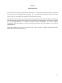
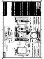
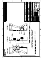
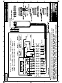
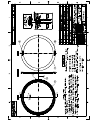
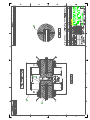
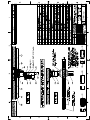
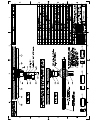
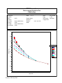
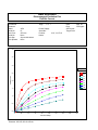
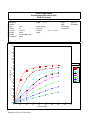
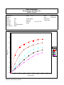
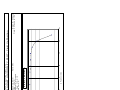
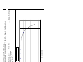
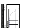
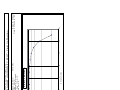
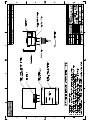
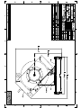
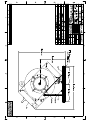
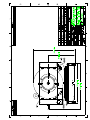
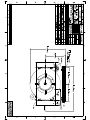
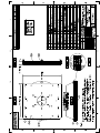
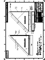
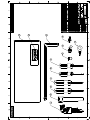
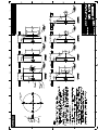
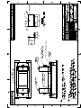
GMW
USER’S MANUAL
MODEL: 3474-140
MODEL: 3474FG-140
250MM ELECTROMAGNET
Date Sold _______________
Magnet SN ______________
PROPRIETARY
THIS DOCUMENT CONTAINS CONFIDENTIAL INFORMATION PROPRIETARY
TO GMW ASSOCIATES. IT MUST NOT BE REPRODUCED OR DISCLOSED TO
OTHERS OR USED IN ANY WAY EXCECPT FOR THE INSTALLATION,
OPERATION OR MAINTENANCE OF GMW ASSOCIATES PRODUCTS.
File No:M3474h.407.doc
GMW
Revision Date: July, 2009
955 Industrial Road, San Carlos, CA 94070 Tel: (650) 802-8292
Email: [email protected] Web site: http://www.gmw.com
Fax: (650) 802-8298
TABLE OF CONTENTS
SPECIFICATIONS
Table 1 Model 3474-140 General Specifications
Table 2 Model 3474-140 Electrical and Water Connections
Section 1
WARNINGS [ Refer to this section before operation of Electromagnet ]
Section 2
INSTALLATION
Facility Requirements
Unpacking Instructions
Mounting Position
Pole Selection and Installation
Electrical Circuit
Interlocks
Cooling
Section 3
OPERATION
General
Calibration
Field Control Operation
Section 4
MAINTENANCE
Section 5
STANDARD OPTIONS
Heat Exchanger Cooling System
Motorized Rotating Drive
Bias Coils
Pole Spacer
Probe Holder
Section 6
CUSTOM OPTIONS
Section 7
EXCITATION CURVES
Section 8
TEST DATA
Magnet System Open Loop Stability Plots
Magnet System Closed Loop Stability Plots
Magnet Field Uniformity Plots
Section 9
DRAWINGS
See list of drawing on next page
Section 10
TABLE OF CONTENTS
DRAWINGS
Elmwood 3450 Thermostats
Johnson Controls 61 Series Flow Switches
Drawing 11801602 3474-140 Electromagnet General Assembly
Drawing 11801603 3474FG-140 Electromagnet General Assembly
Drawing 11901430 3474FG-140 Electromagnet Fixed Gap General Assembly
Drawing 11901360 3474 Electromagnet Water I/O Manifold General Assembly
Drawing 11900120 3474/DF853 Electromagnet Electrical Assembly
Drawing 13900030 3474/DF853 Electromagnet Electrical Wiring
Drawing 11900310 3474/P83C-100150A Electromagnet Electrical Assembly
Drawing 13900380 3474/P83C-100150A Electromagnet Electrical Wiring
Drawing 11900480 3474 Electromagnet Assembly Sequence to Rolling/Rotating Base
Drawing 11900930 3474 Electromagnet Assembly to Rolling/Rotating Base (45 Deg Mtg)
Drawing 11900690 3474 Electromagnet Assembly to Rolling Base (45 Deg Mtg)
Drawing 11900940 3474 Electromagnet Assembly to Rotating Base (45 Deg Mtg)
Drawing 11900950 3474 Electromagnet Assembly to Rolling/Rotating Base (Horz Mtg)
Drawing 11900960 3474 Electromagnet Assembly to Rolling Base (Horz Mtg)
Drawing 11900970 3474 Electromagnet Assembly to Rotating Base (Horz Mtg)
Drawing 11900980 3474 Electromagnet Rolling/Rotating Base Assembly
Drawing 11801800 3474 Electromagnet Rolling Base Assembly
Drawing 11900990 3474 Electromagnet Rotating Base Assembly
Drawing 11900490 3474 Electromagnet Vertical Mounting Assembly
Drawing 17802690 3474 Electromagnet Vertical Mounting Bracket
Drawing 17801730 3474 Electromagnet 45 Deg Mounting Bracket
Drawing 18900010 3474 Electromagnet Tool Kit
Drawing 17801710 3474 Pole Cap [ 250 , 200 , 150 , 100 , 75 , 50 , 25 mm ]
Drawing 18800191 Shipping Crate Assembly
Drawing 18800430 Pole Cap Pair Packing Box
Section 1
SPECIFICATIONS
Table 1. Model 3474-140 General Specifications
------------------------------------------------------------------------------------------------------------------------Pole Diameter
250 mm (10 inch)
Pole Gap *
0 - 160 mm (0 to 6.3 inch)
Standard Pole Caps:
250 mm (10 inch) cylindrical
200 mm (8 inch) tapered
150 mm (6 inch) tapered
100 mm (4 inch) tapered
75 mm (3 inch) tapered
50 mm (2 inch) tapered
2 5 mm (1 inch) tapered
Coil Resistance (20o C)
Maximum Resistance (hot)**
Maximum Power [air]
Maximum Power [water]
series connection
0.44 ohm
0.54 ohm
40A/22V (0.88kW)
140A/76V (10.6kW)
Self Inductance
80mH (measured at 5Hz)
Water Cooling (18° C)
15 liters/m (4 US gpm) 2.0 bar (30 psid)
Overtemperature Interlock
Elmwood 3450G thermal sensor part number
3450G 611-1 L50C 89/16 mounted on each coil
and wired in series. Contact rating 120Vac,0.5A.
Closed below 50o C.
Water Flow Interlock
Johnson Controls flow switch part number F61KD
mounted on outlet side of water circuit.
Contact rating 120Vac/16A, 240Vac/8A non-inductive
Set to open at a flow of less than 10 liter/min (2.7US gpm)
Dimensions
Drawing 11801602/11801603
920mm W x 636 mm D x 864 mm H
(36.2 inch W x 25.0 Inch D x 34.0 inch H)
Weight
1800 kg (3970 lb)
* The 3474FG-140 is a fixed pole gap magnet. Pole gap can be fixed in the range of 5 to 160mm
**CAUTION - The value of maximum coil resistance given should not be exceeded. At this
resistance the coils are at maximum safe temperature for continuous operation.
1-1
Section 1
SPECIFICATIONS
Table 2. Model 3474-140 Electrical and Water Connections
------------------------------------------------------------------------------------------------------------------------DC Current (Refer to Drawing 11801602/11801603)
Right hand terminal Negative
Left Hand terminal Positive
Ground
An M6 screw is provided alongside the dc current connections to enable the magnet frame to be grounded
according to local safety regulations. It is normally appropriate to connect the magnet frame to the power
supply ground.
Interlocks (Refer to Drawing 11801602/11801603)
1
Water flow
2
Water flow
3
Overtemperature
4
Overtemperature
5
No connection
6
No connection
7
No connection
8
Control ground
Normally open. Closed when flow
over 10 l/min (2.7 USgpm)
Normally closed. Open when coil
temperature exceeds 50oC.
Water (Refer to Drawing 11801602/11801603)
outlet 3/8 inch NPT
inlet 3/8 inch NTP
(mating couplings for 1/2 inch hose provided)
---------------------------------------------------------------------------------------------------------------------
CAUTION - Ensure that the high current connections are tight. Loose connections may lead to oxidation
and overheating. The field stability may be degraded and the current terminations damaged.
1-2
Section 2
WARNINGS
REFER TO WARNINGS BELOW BEFORE OPERATING ELECTROMAGNET
1
Personnel Safety
In operation, the magnet fringing field is in excess of 0.5mT (5G). This can cause malfunctioning
of heart pacemakers and other medical implants. We recommend that the fringing field should be
mapped and warning signs be placed outside the 0.5mT (5G) contour. Entry to this region should
be restricted to qualified personnel
2
Ferromagnetic Objects
During operation the magnet exerts strong magnetic attraction towards ferromagnetic objects in the
near vicinity of its pole gap or coils. Loose objects can be accelerated to sufficient velocity to cause
severe personnel injury or damage to the coils or precision pole faces if struck. Keep ferromagnetic
tools clear!
3
Arcing
This magnet stores considerable energy in its field during operation. Do not disconnect any current
lead while under load or the magnetic field energy will be discharged across the interruption causing
hazardous arcing.
4
Coil Hot Resistance
Do not exceed the maximum coil hot resistance given in the specifications or coil overheating and
possible damage may occur.
5
Interlocks
These should always be connected if the magnet is operated unattended, to avoid the possibility of coil
overheating caused by excessive power dissipation or inadequate cooling.
6
Watches, Credit Cards, and Magnetic Disks
Do not move magnetically sensitive items into the close vicinity of the magnet. Even some antimagnetic watches can be damaged when placed in close proximity to the pole gap during operation.
Credit cards, and magnetic disks are affected by magnetic fields as low as 0.5mT (5G). Depending on
the previous operating field and the pole gap, the remanent field in the gap can be in excess of 50G
(5mT) with the magnet power supply off or disconnected.
2-1
GMW
April 11, 2003
Model 3474 System Installation; Minimum Facility Requirements
for Systems with Field Reversal, High Precision Systems and
High Power Systems installed in North America
Floor Space:
Magnet Floor Area: 830 x 830mm (33 x 33”)
Floor Capacity: 1800kg (3,980lb)
Power Supply & Rack Floor Area: 700 x 900mm (28 x 36”)
Floor Capacity: 100kg (220lb)
An area for access to the Magnet and Power Supply must be provided. The total area for the system and
comfortable operation is about 3 x 3m (10 x 10ft). The area should be clean and free from obstructions.
Electrical Service:
MPS Power:
Power Supply:
Voltage:
Systems with Field Reversal or
High Precision Systems.
High Power System
Power10 P83C-100150
Danfysik 853-160A/80V
208Vac, Three Phase,
50 – 60Hz
56 Amps per phase
60 Amps minimum
4 Conductor, 4AWG Min.
Nema 15-60R or equivalent
Nema 15-60P or equivalent
Power10 P86C-100200
208Vac, Three Phase,
50 – 60Hz
74 Amps per phase
80 Amps minimum
4 Conductor, 3AWG Min.
Hard-wired in to electrical panel
(no suitable plugs available)
Current:
Circuit Breaker:
Power Cable:
Mains Outlet:
Mating Plug:
Auxiliary Power for Rack:
Voltage:
115Vac, Single Phase
Current:
15A
Note: Due to liability and insurance reasons, the mains power installation and connections must be completed by
the facility electrician.
Water Cooling:
Water Temperature:
Flow Rate:
Pressure:
Water Hose:
Plumbing Fittings:
15°C to 20°C, non-condensing. Specifications given at 18°C
15 liters / minute (4 US gpm)
2 bar (30 PSID)
12.5mm I.D. (½”), rubber, 2 x 5m long minimum
To connect 12.5mm hose to water source and drain. (It is recommended to have a 50
micron water filter to trap debris on the facility water source and shutoff valves on the
water source and drain.)
System Computer (if required and not provided by GMW):
Processor:
Intel Pentium III, 500MHz PC or better
Memory:
128MB RAM
Free Drive Space:
500MB
Interface:
IEEE-488 (GIPB), National Instruments GPIB-PCII/IIA, P/N: 777158-01
Monitor Resolution:
1024 x 768 or better
Operating System:
Windows ME / 2000 / XP pro / NT4
Lifting Equipment for Installation:
Forktruck or other lifting device with minimum safe lifting capacity of 2000kg
Nylon Slings with minimum safe lifting capacity of 2000kg
Continued…
_____________________________________________________________________________________
955 Industrial Road, San Carlos, CA 94070 Tel: (650) 802-8292 Fax: (650) 802-8298
Email: [email protected] Web site: http://www.gmw.com
GMW
GMW
April 11, 2003
General:
The Purchaser must provide all equipment and labor for delivering the equipment from the delivery dock to the
installation site. You should have a User Manual for the Model 3474 250mm Electromagnet and for the magnet
power supply. Please provide these to the person who will be responsible for the System installation. If you do
not have the User Manual or need to discuss details of the installation please call GMW. If a GMW Engineer is
to supervise the installation any delays caused by inadequate preparation may result in additional charges for
Engineering Time.
Model 3474 System Installation; Check List
Site:
___ Floor space and work space cleared and ready for equipment installation.
___ Appropriate electrical services installed
Materials Required:
___ Power Plugs
___ Power Cable
___ Facility Electrician ready to make mains connections to power supply
at the time of system install
___ Cooling water supply installed with shut-off valves
Materials Required:
___ 12.5mm I.D. (½”) water hose, 5m for source and 5m for drain
___ Water hose fittings appropriate for installed plu mbing
___ Water hose clamps
Misc. Items (to be provided by facility) :
Tools:
___ Power Drill with 5/16” socket (to open magnet crates)
___ 24mm combination wrench (open and box end)
___ 24 mm socket wrench (for attaching the angle brackets to the magnet)
___ ¾” socket wrench (for removal of magnet from shipping crate)
___ Nylon lifting slings, chains, cables and other rigging equipment suitable for lifting magnet.
Other Items:
___ 4” x 4” x 3’ wood blocks. (about 4 – 6 pieces)
___ 3’ x 3’ ¾” plywood
All required materials on this list are to be provided by the facility.
If you are providing your own equipment rack, it must be a minimum of 760mm (30”) deep.
Note: The weight of an assembled 3474 magnet system is just over 4300 lbs. It is not possible to rig and move this
magnet by hand, so use of proper lifting equipment is required (either an appropriately rated lift truck or a traveling
crane). It is the responsibility of the facility to provide the means to move and lift the magnet for assembly on to its
base and move it to its final installed position. If the means to do this is not available in-house, the customer may
be required to hire an outside rigging company to lift and move the magnet. Scheduling of the riggers is the
responsibility of the customer. Should the installation time be extended due to problems with the rigger scheduling,
GMW reserves the right to bill for additional time beyond the original contracted amount.
Important: Due to liability and insurance reasons, the mains power installation and connections must be
completed by the facility electrician. The GMW engineer will not complete the mains power connection. Please
ensure that the facility electrician is available to do this work.
_____________________________________________________________________________________
955 Industrial Road, San Carlos, CA 94070 Tel: (650) 802-8292 Fax: (650) 802-8298
Email: [email protected] Web site: http://www.gmw.com
GMW
Section 3
INSTALLATION
Caution: This is a heavy system. The magnet mass is approximately 1800 kg (4000 lb) so lifting
equipment of this capacity should be used to shift the magnet. Two lifting eyes threaded M33 are
provided and they can be used in several holes. Be sure to ensure the eyes are screwed fully home before
use. Flexible lifting slings of at least 4000kg (9,000 lb) lifting capacity are recommended to avoid
damage to the magnet. All movement, lifting and installation of the 3474 Electromagnet must be under the
supervision of an experienced person to prevent the possibility of serious injury or damage to the
Electromagnet and associated equipment.
Mounting Position
The magnet can be operated in any position. 45 degree mounting angles are available to allow the field
axis to be horizontal with the yoke inclined back at 45o for access from the horizontal and vertical
direction. Refer to drawing 11900930 for showing the 45o mounting arrangement.
Alternatively, vertical mounting brackets can be used to position the field axis vertically. In each case the
magnet should be oriented with the water lines below the electrical connections to reduce the chance of
water leakage shorting electrical connections. Refer to drawing 11900490.
Unpacking Instructions and Damage Inspection
To unpack the electromagnet please use the following procedure (Refer to Drawing 18800191).
1. First remove all of the "Hex Head Screws" located at the lower edge of all the side panels of the
"Crate Top Cover".
2. Gently rock the "Crate Top Cover" to work it loose from the shipping crate base.
3. Use one person on each side of the shipping crate grip the side panels of the Crate Top Cover. Lift
"Crate Top Cover" high enough to clear top of electromagnet, walk cover sideways to clear area and
place on floor.
4. Inspect the magnet to ensure that no damage has occurred to the magnet in shipment. If damage is
evident report the damage in detail to the shipper for claim and simultaneously notify GMW in case
assessment of the damage must be made. If no damage is found proceed with magnet unpacking and
installation.
5. Remove the M16 Hex Bolts that secure the magnet to the steel shipping angle brackets.
6. Remove the hex lag bolts that secure the steel "shipping angle brackets" to shipping crate base, and
remove shipping angle brackets.
7. Install M16 lifting eye and washer to top of magnet yoke, screw down firmly.
8. The magnet is now prepared for final installation, follow the appropriate following procedure to
install to 45°, vertical or direct mounting.
Direct Mounting
1. With suitable lifting equipment (e.g. 4000kg (9000 lb.) minimum safe lifting rating), lift magnet 50mm
(2") clear of shipping crate base.
2. Slide shipping crate base clear.
3. Lower magnet to 50mm (2") above floor.
4. Move magnet to final location and secure using the steel shipping angle brackets. The brackets can be
modified to suit installation space needs.
3-1
Section 3
INSTALLATION
45° Mounting (Refer to Drawing 11900480)
1. With suitable lifting equipment (e.g. 4000kg (9000 lb.) minimum safe lifting rating), lift magnet 50mm
(2") clear of shipping crate base.
1. Slide shipping crate base clear.
2. Lower magnet to 50mm(2") above floor.
3. Move magnet to desired final location and place on 12mm (0.5") plywood sheet and wooden 100mm x
100mm (4" x 4") blocks (refer to figure 2).
4. Install 45° Mounting Brackets using M16 x 30 Hex bolts, flat and spring washers (refer to figure 2).
5. Lift magnet from top lifting eye about 50mm (2") remove 100mm x 100mm (4") wooden block located
next to 45° mounting bracket (refer to figure 2).
6. Lower magnet so that it rests only on the front 100mm x 100mm (4") wooden block (refer to figure 3).
7. Install shackles and lifting sling to BOTH FRONT EYEBOLTS. Caution, keep hands and feet clear of
magnet and 45° brackets during the following operation. Take weight of magnet and push the top front
of the magnet rearward. The magnet weight should move over center. Lower magnet so that it rests on
the 45° mounts (refer to figure 3 and 4).
Rolling or Rolling/Rotating Base Mounting (refer to Drawing 11900480)
Caution do not attempt to move magnet and rolling base or rolling/rotating base until the magnet has been
firmly bolted down to the base (refer to figure 6).
1. To mount on rolling base or rolling/rotating base lift magnet from BOTH FRONT EYEBOLTS high
enough to clear top of base (refer to figure 5).
2. Slide rolling base or rolling/rotating base underneath, lower magnet to 12mm (0.5") above base top
surface (refer to figure 5).
3. Position rolling base or rolling/rotating base so the tapped holes in the base are aligned with the 45°
mounting bracket hole (refer to figure 5).
4. Lower magnet onto rolling base or rolling/rotating base assembly (refer to figure 5).
5. Secure magnet and 45° mounting assembly to rolling base or rolling/rotating base with M16 x 25 long
Hex Head Bolts (refer to figure 6).
6. Move magnet and rolling base or rolling/rotating base to desired location.
7. Screw down the four support legs located on each corner of the rolling or rolling/rotating base until
the wheels clear the floor by 6mm (.25").
8. Secure the support legs with the locknut.
9. Secure rolling/rotating base to an adequate concrete floor to prevent movement and possible injury to
personnel during an earthquake.
3-2
Section 3
INSTALLATION
Pole Cap Selection and Installation (Refer to Drawing 11801602/11801603)
Using the field uniformity and induction curves determine the most desirable pole cap; cylindrical or
tapered. In general:
If a uniform field is required use a cylindrical cap.
If a high field is required use a tapered cap.
The pole caps are machined from low carbon steel. This material is relatively soft and easily damaged.
Since the pole caps are heavy and awkward to manipulate it is advisable to cover the pole faces to protect
them from damage.
Pole cap removal using lifting eye bolt. (Refer to Drawing 11801602/11801603)
1. Turn off the power supply
2. Draw pole caps about 20mm into the pole sleeves, so the tapped M10 holes on the pole cap are still
clear.
3. Fit the pole cap lifting eye bolt firmly into the top tapped hole (M10) of the pole cap to be removed.
4. Draw in the pole cap that is not to be removed until it is flush with the pole sleeve.
5. Tape cardboard or something similar to the face of the pole cap that is not to be removed to protect it
from damage.
6. Support the pole weight, using a sling and overhead crane (approx. weight 38kg/84lbs).
7. Remove the axial retaining stud nut (item 33 on drawing 11801602/11801603).
8. Place the pole cap retaining stud wrench (item 2 on drawing 18900010) onto the end of the retaining
stud (item 6 on drawing 11801602/11801603).
9. Remove retaining stud (item 6 on drawing 11801602/11801603) while supporting the pole cap.
10. Carefully rock the pole cap to break the adhesion to the pole and remove from the magnet
If lifting equipment is not available, the pole cap can be removed using the pole cap removal tool, using
the following procedure.
Pole cap removal using pole cap removal tool. (Refer to Drawing 11801602/11801603)
1. Turn off the power supply
2. Draw pole caps about 20mm into the pole sleeves, so the tapped M10 holes on the pole cap are still
clear.
3. Fit the pole cap removal tools (item 11 on drawing 18900010) firmly into two opposite tapped holes
(M10) on the pole cap to be removed.
4. Tape cardboard or something similar to the face of the other pole cap to protect it from damage.
5. Loosen the axial retaining stud nut 1 turn, but do not remove. (item 33 on drawing
11801602/11801603).
6. Use two people to support the weight of the pole cap (approx. weight 38kg/84lbs).
7. Place the pole cap retaining stud wrench (item 2 on drawing 18900010) onto the end of the retaining
stud (item 6 on drawing 11801602/11801603).
8. Remove retaining stud (item 6 on drawing 11801602/11801603) while supporting the pole cap.
9. Carefully rock the pole cap to break the adhesion to the pole and remove from the magnet
3-3
Section 3
INSTALLATION
Pole cap fitting.
1. Ensure the pole caps, pole cores, and pole sleeves are clean and free from debris.
2. Reverse the above pole cap removal sequence.
Electrical Circuit
Never connect or remove cables from the magnet with the power supply connected. The stored energy in
the magnet can cause arcing resulting in severe injury or equipment damage.
The magnet has two coils which may be connected in series (140A/76V) Model: 3474-140 or in
series/parallel (280A/38V) Model: 3474-280 to match different power supplies. Refer to drawing
11801602/11801603. The power supply cables should be connected directly to the DC current terminals
marked + and -. Recommended current cable is stranded copper of 120mm² cross section (250MCM) for
the 280A/38V coil connections. For 140A/76V coil connections use 70mm² cross section (2/0 AWG)
standard copper current cables. Refer to drawing 13900030 for details.
Because the magnet stores a significant amount of energy in its magnetic field, special care should be taken
to insure that the current terminations are secure and cannot work loose in operation. Local heating at the
terminations can cause rapid oxidation leading to a high contact resistance and high power dissipation at
the terminals. If left unattended this can cause enough local heating to damage the terminals and the coils.
Interlocks
Six thermal sensors Elmwood 3450G Part Number 3450G611-1 L50C 89/16 are wired in series and
terminated in positions 3 and 4 on the Interlock Terminal block. They are normally closed, opening when
the coil central cooling plate temperature exceeds 50oC +/3oC. The flow switch is connected to terminals
1 and 2. The contacts are normally open, closing when the water flow exceeds approx. 10 l/min.
3-4
Section 3
INSTALLATION
Cooling
The Model 3474 can be operated to an average coil temperature of 70oC. Assuming an ambient
laboratory temperature of 20oC and a temperature coefficient of resistivity of 0.00393, the hot resistance
of the coil should not exceed 20% more than the ambient temperature "cold" resistance.
The coil thermal sensor will open when the coil cooling plate temperature exceeds approximately 50oC .
Clean, cool (12oC - 20oC) water at 15 l/min and 2.0 bar (30 psid) should be
used to cool the magnet. The cooling tubes are not electrically connected to the coils so no
electrochemical corrosion will occur. If the water supply contains particulates, a 50 micron filter
should be placed before the input to the magnet to avoid unreliable operation of the flow switch.
For continuous operation of the magnet it may be appropriate to use a recirculating chiller to reduce water
and drainage costs. The chiller capacity will depend on whether cooling is required for the magnet alone
or magnet and power supply. For the Model 3474 Electromagnet alone a suitable chiller is the Neslab
HX-300 with PD-2 pump. Use distilled or deionized water with a biocide to prevent bacterial growth
and corrosion. Do not use corrosion inhibitors in high quality electrical systems since the water
conductivity is increased which can result in increased leakage currents and electrochemical corrosion.
At currents of below 40A for coils that are series connected or 80A for series/parallel connected coils the
Model 3474 can be operated safely without water cooling. However the coil temperature will vary with
the power dissipation. This results in dimensional and permeability changes of the magnet yoke. Air
cooling is not suitable when high field stability is required.
Freon, oil, ethylene glycol or other cooling mediums can be used. The flow required will be
approximately inversely proportional to their specific heats. An experimental determination of the flow
and pressure required will be necessary.
Avoid cooling the magnet below the dew point of the ambient air. Condensation may cause electrical
shorts and corrosion.
During operation the resistance can be checked using a voltmeter across each coil. The voltage will rise
to a constant value once thermal equilibrium has been reached. If it is desired to save water, the flow can
be reduced until the hot resistance is approached. NOTE: This adjustment must be made slowly enough to
allow for the thermal inertia of the coils.
3-5
Section 4
OPERATION
General
The magnet operates as a conventional electromagnet.
1. Adjust the poles to the desired gap with the poles approximately symmetrical about the center magnet
line. To reduce mechanical backlash when the magnetic field is applied, it is best to set the poles by
increasing the gap.
2. Adjust the cooling water flow to about 15 liters/min (4 US gpm). For operation at less than maximum
power the water flow may be correspondingly reduced.
3. Turn on the power supply and increase the current until the desired field is reached.
Calibration
The induction curves may be used to estimate the field in the air gap to within four or five percent.
More accurate field determination may be obtained by deriving experimentally a calibration curve for the
particular pole and air gap combination being used. Magnetic hysteresis in the yoke and poles can cause
an error of 30 to 70G (3 to 7mT) with an arbitrary application of such a calibration curve. This effect may
be reduced to less than one percent by following a prescribed 'current setting schedule' designed to make
the magnet 'forget' its prior magnetic history. The schedule should of course be used both in establishing
the calibration curve and in its subsequent use. A possible schedule would be:
From zero current, increase to maximum current and reduce again to zero current. Increase again to
maximum current and reduce to the current to give the desired field setting. Approaching the desired field
from a higher setting will typically produce better field uniformity. This is because the field changes at
the pole edges will normally lag the field change at the center thereby helping to compensate the radial
decrease in field.
Greater precision in setting up the calibration curve will be achieved with the use of a digital gaussmeter
and by making a numerical table. This table used with an interpolation routine will eliminate the error
associated with reading a graph.
In any event, three points need to be remembered:
1. A calibration curve or table is only as good as the precision employed in generating it.
2. The field is defined only at the point it is measured. It will generally be different at a different point in
the air gap. For example, the induction curves refer to the field on the pole axis and at the center of the air
gap (median plane).
3. The field is most directly a function of the current in the magnet coils. Voltage across the coils is not a
good measure of field since the electrical resistance of the coils depends on the temperature (about 0.4%
per degree Celsius).
4-1
Section 4
OPERATION
Field Control Operation
The necessity to use calibration curves can be avoided by using a field controller to sense the magnetic
field and provide a corresponding power supply control signal through the power supply programming
inputs. Contact GMW for suitable instrumentation.
4-2
Section 5
MAINTENANCE
Periodically check that the pole adjustment mechanism is clean, properly lubricated and free of grit and
dirt, which may cause binding of the mechanism. Be very careful not to damage the relatively soft pole
surface since this may degrade the magnetic field uniformity in the gap.
Note that the surface treatments used provide good corrosion protection but in order to maintain the
inherent mechanical precision of the magnet, heavy build-up of plating materials is deliberately avoided.
As a result, high humidity or otherwise seriously corrosive atmospheres can cause corrosion.
Periodically apply an appropriate corrosion protection, particularly when the magnet is stored for an
extended period.
Check the cooling water circuit to ensure the water is clean and free of debris and bacterial growth.
Ensure the in-line water filter is clean.
5-1
Section 6
STANDARD OPTIONS
Section 7
CUSTOM OPTIONS
Section 8
EXCITATION CURVES
GMW Associates
Electromagnet Excitation Plot
Field Vs Gap
Contract No:
Customer:
Page:
1 of 1
Model:
Serial No:
3474
Power Supply:
Serial No:
Pole Face:
Serial No:
Pole Gap:
Pole Spacers:
As per table below
None
As per table below
None
Position:
Notes:
Date:
Engr:
Feb 04,2003
Y. Qin
Set Current: 140 Amps
Target Field:
X=0, Y=0, Z=0
4.0
3.5
3.0
Pole Face
Field in Tesla
2.5
25
50
75
2.0
100
150
200
250
1.5
1.0
0.5
0.0
0
20
40
60
80
Gap in mm
Filename: 3474 Gap-Field
100
120
140
160
GMW Associates
Electromagnet Excitation Plot
Field Vs Current
Contract No:
Customer:
Page:
1 of 7
Model:
Serial No:
3474
07
Power Supply:
Serial No:
Pole Face:
Serial No:
Pole Gap:
Pole Spacers:
250 mm
None
As per table below
None
Position:
Notes:
Date:
Engr:
April, 93
G.Douglas
Set Current:
Target Field:
X=0, Y=0, Z=0
4.0
3.5
3.0
Gap mm
10
2.5
Field in Tesla
20
30
40
2.0
50
70
100
150
1.5
1.0
0.5
0.0
0
20
40
60
80
100
Current in Amps
Filename: 3474 Ex 250-10-150.xls
120
140
160
180
GMW Associates
Electromagnet Excitation Plot
Field Vs Current
Contract No:
Customer:
Page:
2 of 7
Model:
Serial No:
3474
09
Power Supply:
Serial No:
Pole Face:
Serial No:
Pole Gap:
Pole Spacers:
200 mm
None
As per table below
None
Position:
Notes:
Date:
Engr:
Feb 12, 97
E.Schulze
Set Current:
Target Field:
X=0, Y=0, Z=0
4.0
3.5
3.0
Gap mm
10
2.5
Field in Tesla
20
30
40
2.0
50
70
100
150
1.5
1.0
0.5
0.0
0
20
40
60
80
100
Current in Amps
Filename: 3474 Ex 200-10-150.xls
120
140
160
180
GMW Associates
Electromagnet Excitation Plot
Field Vs Current
Contract No:
Customer:
Page:
3 of 7
Model:
Serial No:
3474
07
Power Supply:
Serial No:
Pole Face:
Serial No:
Pole Gap:
Pole Spacers:
150 mm
None
As per table below
None
Position:
Notes:
Date:
Engr:
April, 93
G.Douglas
Set Current:
Target Field:
X=0, Y=0, Z=0
4.0
3.5
3.0
Gap mm
10
2.5
Field in Tesla
20
30
40
2.0
50
70
100
150
1.5
1.0
0.5
0.0
0
20
40
60
80
100
Current in Amps
Filename: 3474 Ex 150-10-150.xls
120
140
160
180
GMW Associates
Electromagnet Excitation Plot
Field Vs Current
Contract No:
Customer:
Page:
4 of 7
Model:
Serial No:
3474
01
Power Supply:
Serial No:
Pole Face:
Serial No:
Pole Gap:
Pole Spacers:
100 mm
None
As per table below
None
Position:
Notes:
Date:
Engr:
March 03, 86
R.Gummer
Set Current:
Target Field:
X=0, Y=0, Z=0
4.0
3.5
3.0
Gap mm
2.5
Field in Tesla
10
20
30
2.0
40
50
60
1.5
1.0
0.5
0.0
0
20
40
60
80
100
Current in Amps
Filename: 3474 Ex 100-10-150.xls
120
140
160
180
GMW Associates
Electromagnet Excitation Plot
Field Vs Current
Contract No:
Customer:
Page:
5 of
Model:
Serial No:
3474
48
Power Supply:
Serial No:
Pole Face:
Serial No:
Pole Gap:
Pole Spacers:
75 mm
None
As per table below
None
Position:
Notes:
7
Date:
Engr:
Feb 4, 03
Y.Qin
Set Current:
Target Field:
X=0, Y=0, Z=0
4.0
3.5
3.0
Gap mm
06
10
2.5
Field in Tesla
20
30
40
2.0
50
70
100
150
1.5
1.0
0.5
0.0
0
20
40
60
80
100
Current in Amps
Filename: 3474 Ex 75-10-150
120
140
160
180
GMW Associates
Electromagnet Excitation Plot
Field Vs Current
Contract No:
Customer:
Page:
6 of 7
Model:
Serial No:
3474
01
Power Supply:
Serial No:
Pole Face:
Serial No:
Pole Gap:
Pole Spacers:
50
None
As per table below
None
Position:
Notes:
Date:
Engr:
March 03, 86
R.Gummer
Set Current:
Target Field:
X=0, Y=0, Z=0
4.0
3.5
3.0
Gap mm
Field in Tesla
2.5
10
20
30
2.0
40
50
1.5
1.0
0.5
0.0
0
20
40
60
80
100
Current in Amps
Filename: 3474 Ex 50-10-150.xls
120
140
160
180
GMW Associates
Electromagnet Excitation Plot
Field Vs Current
Contract No:
Customer:
Page:
7 of 7
Model:
Serial No:
3474
01
Power Supply:
Serial No:
Pole Face:
Serial No:
Pole Gap:
Pole Spacers:
25
None
As per table below
None
Position:
Notes:
Date:
Engr:
March 03, 86
R.Gummer
Set Current:
Target Field:
X=0, Y=0, Z=0
4.0
3.5
3.0
Gap mm
Field in Tesla
2.5
10
20
30
2.0
40
50
1.5
1.0
0.5
0.0
0
20
40
60
80
100
Current in Amps
Filename: 3474 Ex 25-10-150.xls
120
140
160
180
Section 9
TEST DATA
-80
3474-140
09
C7955
100 Amp.
-60
-40
-20
0
X Position (mm)
20
Pole SN:
Field vs Position
Pole Face: 150 mm
Pole Gap: 30 mm
Pole Spacers: Not fitted
Fixed Axis: Y=0, Z=0
Variable Axis: X
40
60
80
Engr: E. Schulze
Date: 29 January, 1997
GMW ASSOCIATES
LABORATORY ELECTROMAGNET UNIFORMITY PLOT - Field Vs Position
Filename: SC7955 Uniformity Plot 2.507
2.0600000
2.0800000
2.1000000
2.1200000
2.1400000
2.1600000
2.1800000
2.2000000
2.2200000
2.2400000
Model
Serial No
Contract No:
Note:
Field (Tesla)
-80
3474-140
09
C7955
140 Amp
-60
-40
-19
-20
0
X Position (mm)
20
Pole SN:
Field vs Position
2.0049200
Pole Face: 150 mm
Pole Gap: 30 mm
Pole Spacers: Not fitted
Fixed Axis: Y=0, Z=0
Variable Axis: X
19
40
2.0088720
60
80
Engr: E. Schulze
Date: 29 January, 1997
GMW ASSOCIATES
LABORATORY ELECTROMAGNET UNIFORMITY PLOT - Field Vs Position
Filename: SC7955 Uniformity Plot 2.507
2.2000000
2.2200000
2.2400000
2.2600000
2.2800000
2.3000000
2.3200000
2.3400000
2.3600000
2.3800000
Model
Serial No
Contract No:
Note:
Field (Tesla)
-80
3474-140
09
C7955
100 Amp.
-60
-40
-20
0
X Position (mm)
20
Pole SN:
Field vs Position
Pole Face: 150 mm
Pole Gap: 40 mm
Pole Spacers: Not fitted
Fixed Axis: Y=0, Z=0
Variable Axis: X
40
60
80
Engr: E. Schulze
Date: 29 January, 1997
GMW ASSOCIATES
LABORATORY ELECTROMAGNET UNIFORMITY PLOT - Field Vs Position
Filename: SC7955 Uniformity Plot 3.507
1.7800000
1.8000000
1.8200000
1.8400000
1.8600000
1.8800000
1.9000000
1.9200000
1.9400000
Model
Serial No
Contract No:
Note:
Field (Tesla)
-80
3474-140
09
C7955
140 Amp
-60
-40
-19
-20
0
X Position (mm)
20
Pole SN:
Field vs Position
2.0049200
Pole Face: 150 mm
Pole Gap: 40 mm
Pole Spacers: Not fitted
Fixed Axis: Y=0, Z=0
Variable Axis: X
19
40
2.0088720
60
80
Engr: E. Schulze
Date: 29 January, 1997
GMW ASSOCIATES
LABORATORY ELECTROMAGNET UNIFORMITY PLOT - Field Vs Position
Filename: SC7955 Uniformity Plot 3.507
1.9600000
1.9800000
2.0000000
2.0200000
2.0400000
2.0600000
2.0800000
2.1000000
2.1200000
2.1400000
2.1600000
2.1800000
Model
Serial No
Contract No:
Note:
Field (Tesla)
-80
3474-140
09
C7955
100 Amp.
-60
-40
-20
0
X Position (mm)
20
Pole SN:
Field vs Position
Pole Face: 150 mm
Pole Gap: 50 mm
Pole Spacers: Not fitted
Fixed Axiz: Y=0, Z=0
Variable Axis: X
40
60
80
Engr: E. Schulze
Date: 29 January, 1997
GMW ASSOCIATES
LABORATORY ELECTROMAGNET UNIFORMITY PLOT - Field Vs Position
Filename: SC7955 Uniformity Plot 4.507
1.5000000
1.5200000
1.5400000
1.5600000
1.5800000
1.6000000
1.6200000
1.6400000
Model
Serial No
Contract No:
Note:
Field (Tesla)
-80
3474-140
09
C7955
140 Amp
-60
-40
-19
-20
0
X Position (mm)
20
Pole SN:
Field vs Position
2.0049200
Pole Face: 150 mm
Pole Gap: 50 mm
Pole Spacers: Not fitted
Fixed Axiz: Y=0, Z=0
Variable Axis: X
19
40
2.0088720
60
80
Engr: E. Schulze
Date: 29 January, 1997
GMW ASSOCIATES
LABORATORY ELECTROMAGNET UNIFORMITY PLOT - Field Vs Position
Filename: SC7955 Uniformity Plot 4.507
1.7400000
1.7600000
1.7800000
1.8000000
1.8200000
1.8400000
1.8600000
1.8800000
1.9000000
1.9200000
1.9400000
Model
Serial No
Contract No:
Note:
Field (Tesla)
-80
3474-140
09
C7955
100 Amp.
-60
-40
-20
0
X Position (mm)
20
Pole SN:
Field vs Position
Pole Face: 150 mm
Pole Gap: 60 mm
Pole Spacers: Not fitted
Fixed Axis: Y=0, Z=0
Variable Axis: X
40
60
80
Engr: E. Schulze
Date: 29 January, 1997
GMW ASSOCIATES
LABORATORY ELECTROMAGNET UNIFORMITY PLOT - Field Vs Position
Filename: SC7955 Uniformity Plot 5.507
1.2800000
1.3000000
1.3200000
1.3400000
1.3600000
1.3800000
1.4000000
1.4200000
1.4400000
Model
Serial No
Contract No:
Note:
Field (Tesla)
-80
3474-140
09
C7955
140 Amp
-60
-40
-19
-20
0
X Position (mm)
20
Pole SN:
Field vs Position
2.0049200
Pole Face: 150 mm
Pole Gap: 60 mm
Pole Spacers: Not fitted
Fixed Axis: Y=0, Z=0
Variable Axis: X
19
40
2.0088720
60
80
Engr: E. Schulze
Date: 29 January, 1997
GMW ASSOCIATES
LABORATORY ELECTROMAGNET UNIFORMITY PLOT - Field Vs Position
Filename: SC7955 Uniformity Plot 5.507
1.5600000
1.5800000
1.6000000
1.6200000
1.6400000
1.6600000
1.6800000
1.7000000
1.7200000
1.7400000
Model
Serial No
Contract No:
Note:
Field (Tesla)
-80
3474-140
09
C7955
100A
-60
-40
-20
0
X Position (mm)
20
Pole SN:
Field vs Position
Pole Face: 150 mm
Pole Gap: 70 mm
Pole Spacers: Not fitted
Fixed Axis: Y=0, Z=0
Variable Axis: X
40
60
80
Engr: Mike Duffy
Date: 28 January, 1997
GMW ASSOCIATES
LABORATORY ELECTROMAGNET UNIFORMITY PLOT - Field Vs Position
Filename: SC7955 Uniformity Plot 6.507
1.1200000
1.1400000
1.1600000
1.1800000
1.2000000
1.2200000
1.2400000
1.2600000
Model
Serial No
Contract No:
Note:
Field (Tesla)
-80
3474-140
09
C7955
140A
-60
-40
-19
-20
0
X Position (mm)
20
Pole SN:
Field vs Position
2.0049200
Pole Face: 150 mm
Pole Gap: 70 mm
Pole Spacers: Not fitted
Fixed Axis: Y=0, Z=0
Variable Axis: X
19
40
2.0088720
60
80
Engr: Mike Duffy
Date: 28 January, 1997
GMW ASSOCIATES
LABORATORY ELECTROMAGNET UNIFORMITY PLOT - Field Vs Position
Filename: SC7955 Uniformity Plot 6.507
1.4000000
1.4200000
1.4400000
1.4600000
1.4800000
1.5000000
1.5200000
1.5400000
1.5600000
1.5800000
Model
Serial No
Contract No:
Note:
Field (Tesla)
-80
3474-140
09
C7955
100 Amp.
-60
-40
-20
0
X Position (mm)
20
Pole SN:
Field vs Position
Pole Face: 200 mm
Pole Gap: 30 mm
Pole Spacers: Not fitted
Fixed Axis: Y=0, Z=0
Variable Axis: X
40
60
80
Engr: E. Schulze
Date: 12 February, 1997
GMW ASSOCIATES
LABORATORY ELECTROMAGNET UNIFORMITY PLOT - Field Vs Position
Filename: SC7955 Uniformity Plot 12.507
2.0020000
2.0040000
2.0060000
2.0080000
2.0100000
2.0120000
2.0140000
2.0160000
2.0180000
2.0200000
Model
Serial No
Contract No:
Note:
Field (Tesla)
-80
3474-140
09
C7955
140 Amp
-60
-40
-19
-20
0
X Position (mm)
20
Pole SN:
Field vs Position
2.0049200
Pole Face: 200 mm
Pole Gap: 30 mm
Pole Spacers: Not fitted
Fixed Axis: Y=0, Z=0
Variable Axis: X
19
40
2.0088720
60
80
Engr: E. Schulze
Date: 12 February, 1997
GMW ASSOCIATES
LABORATORY ELECTROMAGNET UNIFORMITY PLOT - Field Vs Position
Filename: SC7955 Uniformity Plot 12.507
2.1200000
2.1250000
2.1300000
2.1350000
2.1400000
2.1450000
2.1500000
Model
Serial No
Contract No:
Note:
Field (Tesla)
-80
3474-140
09
C7955
100 Amp.
-60
-40
-20
X Position (mm)
0
20
Pole SN:
Field vs Position
Pole Face: 200 mm
Pole Gap: 70 mm
Pole Spacers: Not fitted
Fixed Axis: Y=0, Z=0
Variable Axis: X
40
60
80
Engr: E. Schulze
Date: 12 February, 1997
GMW ASSOCIATES
LABORATORY ELECTROMAGNET UNIFORMITY PLOT - Field Vs Position
Filename: SC7955 Uniformity Plot 15.507
1.1900000
1.1950000
1.2000000
1.2050000
1.2100000
1.2150000
1.2200000
Model
Serial No
Contract No:
Note:
Field (Tesla)
-80
3474-140
09
C7955
140 Amp
-60
-40
-19
-20
X Position (mm)
0
20
Pole SN:
Field vs Position
2.0049200
Pole Face: 200 mm
Pole Gap: 70 mm
Pole Spacers: Not fitted
Fixed Axis: Y=0, Z=0
Variable Axis: X
19
40
2.0088720
60
80
Engr: E. Schulze
Date: 12 February, 1997
GMW ASSOCIATES
LABORATORY ELECTROMAGNET UNIFORMITY PLOT - Field Vs Position
Filename: SC7955 Uniformity Plot 15.507
1.4350000
1.4400000
1.4450000
1.4500000
1.4550000
1.4600000
1.4650000
1.4700000
Model
Serial No
Contract No:
Note:
Field (Tesla)
-80
3474-140
09
C7955
100 Amp.
-60
-40
-20
X Position (mm)
0
20
Pole SN:
Field vs Position
Pole Face: 200 mm
Pole Gap: 100 mm
Pole Spacers: Not fitted
Fixed Axis: Y=0, Z=0
Variable Axis: X
40
60
80
Engr: E. Schulze
Date: 12 February, 1997
GMW ASSOCIATES
LABORATORY ELECTROMAGNET UNIFORMITY PLOT - Field Vs Position
Filename: SC7955 Uniformity Plot 16.507
0.8450000
0.8500000
0.8550000
0.8600000
0.8650000
0.8700000
0.8750000
0.8800000
0.8850000
0.8900000
Model
Serial No
Contract No:
Note:
Field (Tesla)
-80
3474-140
09
C7955
140 Amp
-60
-40
-19
-20
X Position (mm)
0
20
Pole SN:
Field vs Position
2.0049200
Pole Face: 200 mm
Pole Gap: 100 mm
Pole Spacers: Not fitted
Fixed Axis: Y=0, Z=0
Variable Axis: X
19
40
2.0088720
60
80
Engr: E. Schulze
Date: 12 February, 1997
GMW ASSOCIATES
LABORATORY ELECTROMAGNET UNIFORMITY PLOT - Field Vs Position
Filename: SC7955 Uniformity Plot 16.507
1.0900000
1.0950000
1.1000000
1.1050000
1.1100000
1.1150000
1.1200000
1.1250000
1.1300000
1.1350000
1.1400000
Model
Serial No
Contract No:
Note:
Field (Tesla)
+5,3 +5, -5
6
-5, -5, -5
Position X, Y, Z (mm)
5+5, +5, +5
7
19
-5, -5, +58
Pole SN:
Field vs Position
2.0049200
-5,
4 +5, +5
Filename: SC7955 Uniformity Plot Cube @1.0T.507
-5, +5,
2 -5
100ppm
-19
Pole Face: 200 mm
Pole Gap: 50 mm
Pole Spacers: Fitted
Fixed Axis:
Variable Axis: X, Y, Z
+5, -5, -5
9
2.0088720
+5, -5,
10+5
0, 11
0, 0
Engr: E. Schulze
Date: 14 February, 1997
GMW ASSOCIATES
LABORATORY ELECTROMAGNET UNIFORMITY PLOT - 10mm Cube
3474-140
09
C7955
1.0T
1.0021200
0, 0,
10
1.0021400
1.0021600
1.0021800
1.0022000
1.0022200
1.0022400
1.0022600
Model
Serial No
Contract No:
Note:
Field (Tesla)
+5,3 +5, -5
-5,
4 +5, +5
Filename: SC7955 Uniformity Plot Cube @1.0T.507
-5, +5,
2 -5
100ppm
6
-5, -5, -5
Position X, Y, Z (mm)
5+5, +5, +5
7
-5, -5, +58
Pole SN:
Field vs Position
Pole Face: 200 mm
Pole Gap: 50 mm
Pole Spacers: Fitted
Fixed Axis:
Variable Axis: X, Y, Z
+5, -5, -5
9
+5, -5,
10+5
0, 11
0, 0
Engr: E. Schulze
Date: 14 February, 1997
GMW ASSOCIATES
LABORATORY ELECTROMAGNET UNIFORMITY PLOT - 10mm Cube
3474-140
09
C7955
1.5T
1.4999000
0, 0,
10
1.4999200
1.4999400
1.4999600
1.4999800
1.5000000
1.5000200
1.5000400
1.5000600
1.5000800
1.5001000
Model
Serial No
Contract No:
Note:
Field (Tesla)
1.53950000
-20
100ppm
3474-140
09
C7955
100A
-15
50ppm
-10
-5
5
X or Z Position (mm)
0
Pole Face: 200 mm
Pole Gap: 50 mm
Pole Spacers: Fitted
Fixed Axis: Y=0
Variable Axis: X, Z
Filename: SC7955 Uniformity Plot with spacers x & z axis.507
-25
1.53955000
1.53960000
1.53965000
1.53970000
1.53975000
1.53980000
1.53985000
1.53990000
Model:
Serial No:
Contract No:
Note:
10
Pole SN:
15
20
25
X axis, Z=0
-25ppm
+25ppm
-50ppm
+50ppm
Z axis, x=20
Z axis, x=10
Z axis, x=5
Z axis, x=0
Z axis, x=-5
Z axis, x=-10
Z axis, x=-20
Engr: E. Schulze
Date: 14 February, 1997
GMW ASSOCIATES
LABORATORY ELECTROMAGNET UNIFORMITY Z-Axis as a function of X-Axis
GMW ASSOCIATES
LABORATORY ELECTROMAGNET STABILITY PLOT
Model:
3474-140
Pole Face: 200 mm
Pole SN:
Serial No:
09
Pole Gap: 50 mm
Contract No: C7955
Pole Spacers: Fitted
Note:
140A
Fixed Axis: X=0, Y=0, Z=0
Field measurement done with MetroLab 2025 & 1062-5 NMR system.
Engr: E. Schulze
Date: 14 February, 1997
Field Stability
1.7649000
1.7648500
1.7648000
1.7647500
Field
10ppm
1.7647000
1.7646500
1.7646000
1.7645500
16:19
16:33
16:48
17:02
17:16
17:31
17:45
18:00
Time Index
Water temp, in
Temperature Stability
Water temp, out
Ambient air temp
30
25
Temp °C
20
15
10
5
0
16:19
16:33
16:48
17:02
17:16
Time index
Filename: SC7955 Stability Plot, 140 Amps.507
17:31
17:45
18:00
GMW ASSOCIATES
LABORATORY ELECTROMAGNET STABILITY PLOT
Model:
3474-140
Pole Face: 200 mm
Pole SN:
Serial No:
09
Pole Gap: 50 mm
Contract No: C7955
Pole Spacers: Fitted
Note:
56A
Fixed Axis: X=0, Y=0, Z=0
Field measurement done with MetroLab 2025 & 1062-5 NMR system.
Engr: E. Schulze
Date: 25 February, 1997
Field Stability
1.0022100
1.0022000
1.0021900
10ppm
Field
1.0021800
1.0021700
1.0021600
1.0021500
1.0021400
15:44
16:13
16:42
17:11
17:39
18:08
18:37
19:06
Time Index
Water temp, in
Temperature Stability
Water temp, out
Ambient air temp
25
20
Temp °C
15
10
5
0
15:44
16:13
16:42
17:11
17:39
Time Index
Filename: SC7955 Stability Plot, 1.0T.507
18:08
18:37
19:06
Section 10
DRAWINGS