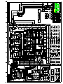
1
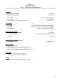
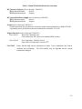
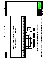
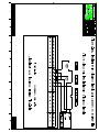
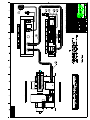
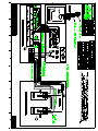
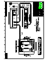
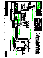
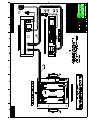
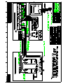
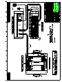
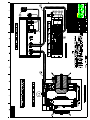
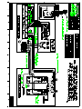
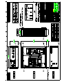
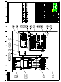
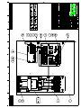
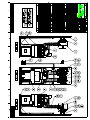
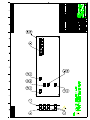
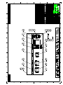
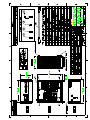
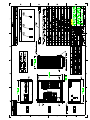
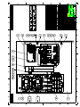
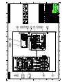
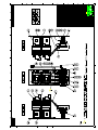
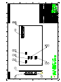
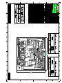
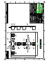
GMW
USER’S MANUAL
MODEL: 5970-80
MODEL: 5970-160
CURRENT REVERSAL SWITCH
Date Sold: _____________
Serial number: __________
PROPRIETARY
THIS DOCUMENT CONTAINS CONFIDENTIAL INFORMATION PROPRIETARY TO GMW
ASSOCIATES. IT MUST NOT BE REPRODUCED OR DISCLOSED TO OTHERS OR
USED IN ANY WAY EXCEPT FOR THE INSTALLATION, OPERATION OR MAINTENANCE
OF GMW ASSOCIATES PRODUCTS.
File No: M5970i.407
GMW
955 Industrial Road, San Carlos, CA 94070 Tel: (650) 802-8292
Email: [email protected] Web site: http://www.gmw.com
Revision Date: March 22, 2000
Fax: (650) 802-8298
TABLE OF CONTENTS
SPECIFICATIONS
Model: 5970-80
Model: 5970-160
Section 1
WARNINGS
Refer to this section before operation of Current Reversal Switch.
Section 2
INSTALLATION
Unpacking Instructions.
Mounting Position.
Electrical Circuit.
Section 3
OPERATION
General.
To reverse polarity.
Section 4
ANALOG DEVICE INTERFACE (Option)
General.
ADI Installation Kit.
GPIB Installation Kit
ADI Field Installation
ADI commands.
Software Drivers
Section 5
MAINTENANCE
Section 6
DRAWINGS
Section 7
Drawing 13900360 5970-80/160 Reversing Switch Schematic, [shown with optional ADI]
Drawing 13900361 5970-80/160 Reversing Switch Schematic, [shown without optional ADI]
Drawing 13900311 5970-80/160 Remote Control Schematic, [shown using internal power supply]
Drawing 13900312 5970-80/160 Remote Control Schematic, [shown using external power supply]
Drawing 13900370 5970-160 Contactor Assembly Schematic
Drawing 11900790 5403/RS/P62B-3066A Electrical Assembly
Drawing 13900290 5403/RS/P62B-3066A Electrical Wiring
Drawing 11900780 3472-50/RS/P62B-4050A Electrical Assembly
Drawing 13900280 3472-50/RS/P62B-4050A Electrical Wiring
Drawing 11900770 3472-70/RS/P63C-60110A Electrical Assembly
Drawing 13900270 3472-70/RS/P63C-60110A Electrical Wiring
Drawing 11900760 3473-50/RS/P62B-4050A Electrical Assembly
Drawing 13900260 3473-50/RS/P62B-4050A Electrical Wiring
Drawing 11900750 3473-70/RS/P63C-60110A Electrical Assembly
Drawing 13900250 3473-70/RS/P63C-60110A Electrical Wiring
Drawing 11900860 3474-140/RS/P83C-100150A Electrical Assembly
Drawing 13900390 3474-140/RS/P83C-100150A Electrical Wiring
Continued
DRAWINGS (continued)
Drawing 11900561 5970-80 General Assembly, [shown with optional ADI]
Drawing 11900562 5970-80 General Assembly, [shown without optional ADI]
Drawing 11900571 5970-80 Base Plate Assembly, [shown with optional ADI]
Drawing 11900572 5970-80 Base Plate Assembly, [shown without optional ADI]
Drawing 11900580 5970-80 Contactor Assembly
Drawing 11900590 5970-80 Front Panel Assembly
Drawing 11900601 5970-80 Back Panel Assembly, [shown with optional ADI]
Drawing 11900602 5970-80 Back Panel Assembly, [shown without optional ADI]
Drawing 11900611 5970-160 General Assembly, [shown with optional ADI]
Drawing 11900612 5970-160 General Assembly, [shown without optional ADI]
Drawing 11900621 5970-160 Base Plate Assembly, [shown with optional ADI]
Drawing 11900622 5970-160 Base Plate Assembly, [shown without optional ADI]
Drawing 11900630 5970-160 Contactor Assembly
Drawing 11900640 5970-160 Front Panel Assembly
Drawing 11900651 5970-160 Back Panel Assembly, [shown with optional ADI]
Drawing 11900652 5970-160 Back Panel Assembly, [shown without optional ADI]
Drawing 15900000 5970-80/160 Control PCB Assembly
Drawing 15900010 5970-80/160 Front Panel PCB Assembly
Section 1
SPECIFICATIONS
Table 1. Model 5970-80 Specifications
-------------------------------------------------------------------------------------------------------------------Electrical
DC Voltage (maximum):
DC Current (maximum):
100 Volts
80 Amps
AC Voltage:
AC Current:
DC Internal power supply (control power):
Fuse Ratings
AC Input:
AC Input:
DC Interlock:
100-125 or 200-250 Volts
2.0/1.0 Amps
24VDC/2.4A
for 115V use 20 x 5 mm 2.0Amp SLO-BLOW
for 230V use 20 x 5 mm 1.0Amp SLO-BLOW
use 20 x 5 mm 2Amp SLO-BLOW
Electrical Connections
DC Current: (up to 80A max)
DC Control wiring:
AC Power:
Analog Device Interface (Option)
GPIB Plug.
M6 Stud
Phoenix Plug/Header Type: MSTB
IEC320
GPIB Female
Spare Parts Kit
Pilot lamps 12V (x 2).
Fuses type 20 x5 mm 1.0 Amp SLO-BLOW (x 5)
Fuses type 20 x5 mm 2.0 Amp SLO-BLOW (x 5)
Dimensions
483 mm W x 541mm D x 177 mm H.
(19.0 inch W x 21.3 Inch D x 7.0 inch H).
Weight
20kg (44 lb), excluding interconnecting cables.
1-1
Section 1
SPECIFICATIONS
Table 1. Model 5970-160 Specifications
-------------------------------------------------------------------------------------------------------------------Electrical
DC Voltage (maximum):
DC Current (maximum):
100 Volts
160 Amps
AC Voltage:
AC Current:
DC Internal power supply (control power):
Fuse Ratings
AC Input:
AC Input:
DC Interlock:
100-125 or 200-250 Volts
2.0/1.0 Amps
24VDC/2.4A
for 115V use 20 x 5 mm 2.0Amp SLO-BLOW
for 230V use 20 x 5 mm 1.0Amp SLO-BLOW
use 20 x 5 mm 2Amp SLO-BLOW
Electrical Connections
DC Current: (up to 160A max)
DC Control wiring:
AC Power:
Analog Device Interface (Option)
GPIB Plug.
M12 Stud
Phoenix Plug/Header Type: MSTB
IEC320
GPIB Female
Spare Parts Kit
Pilot lamps 12V (x 2).
Fuses type 20 x5 mm 1.0 Amp SLO-BLOW (x 5)
Fuses type 20 x5 mm 2.0 Amp SLO-BLOW (x 5)
Dimensions
483 mm W x 495 mm D x 266 mm H.
(19.0 inch W x 19.5 inch D x 10.5 inch H)
Weight
22 kg (48 lb), excluding interconnecting cables.
1-2
Section 2
WARNINGS
REFER TO WARNINGS BELOW
BEFORE OPERATING CURRENT REVERSAL SWITCH
1
AC Power
Ensure that the VOLTAGE SELECTOR has been set to the correct input voltage before
applying AC Input Power. To check the Voltage Selector first turn off power on the AC input
receptacle and remove the AC input plug. The voltage displayed next to the triangle on the lower
right hand side of the AC input receptacle is the voltage setting. To change the voltage settings
insert a small bladed screwdriver into the slot on the top of the Fuse Drawer located directly
below the ground pin on the AC input receptacle and pull the Fuse Drawer out. Check the the
correct fuse is inserted in the correct location. A 2.0A fuse is used for 115 Vac and 1.0A fuse used
for 230Vac The Fuse Drawer should then be rotated 180° and reinserted. Check that the correct
voltage setting is displayed next to the triangle on the lower right hand side of the AC input
receptacle.
2
DC Interlock
Check the operation of the DC Interlock circuit before operating the Reversal Switch. Turn on the
DC Power Supply and increase the output voltage to 2 volts. The High Current Interlock light on
the front panel should illuminate and relay RL2 should be energized. If the lamp does not
illuminate check the High Current Interlock circuit and remedy the problem before using the
Reversal Switch.
3
Arcing
The magnet stores considerable energy in its field during operation. Do not disconnect any high
current or ac power lead while under load or the magnetic field energy may be discharged across
the interruption causing severe and hazardous arcing.
4
Current Rating
Do not exceed the current rating for the Current Reversal Switch given in the specification tables
in section 1 of this User’s Manual. Exceeding the current rating is dangerous and will damage the
internal components. Damage caused by using the Current Reversal Switch at higher currents than
specified will void the warranty.
5
Watches, Credit Cards, Magnetic Discs and Pacemakers
Do not move magnetically sensitive items into the close vicinity of the magnet. Even some antimagnetic watches can be damaged when placed in close proximity to the pole gaps during
operation. Credit cards, magnetic discs and pacemakers may be affected by magnetic fields as low
as 5G (0.5mT).
2-1
Table 2. Model 5970-80/160 Electrical Connections
DC Current to Magnet (refer to drawing 13900360/1)
TB1 Left hand terminal:
Positive
TB1 Right hand terminal:
Negative
DC Current from Power Supply (refer to drawing 13900360/1)
TB2 Left hand terminal:
Positive
TB2 Right hand terminal:
Negative
Ground (refer to drawing 13900360/1)
Ground connections are provided at two locations on the main terminal block on Model 5970-80.
A grounding stud is provided near the main terninal block on Model: 5970-160.
Magnet Interlocks (refer to drawing 13900360/1)
Pin 1 & Pin 2
Water flow: Normally open.
Closed when flow OK. (not used in standard GMW systems)
Pin 3 & Pin 4
Over temperature: Normally closed.
Open when coil temperature exceeds 50oC.
CAUTION : Ensure that the high current connections are tight. Loose connections may lead to
oxidation and overheating. The field stability may be degraded and the current
terminations damaged.
2-2
Section 3
INSTALLATION
Unpacking Instructions
The Model 5970-80/160 is supplied assembled. If damage is evident, report the damage in detail to
the shipper for claim and simultaneously notify GMW in case assessment of the damage must be made.
Included in the carton should be:
1 x 5970-80/160 Current reversing Switch
1 x Manual
1 x Spare Parts Kit
* 1 x ADI-123 (Optional)
* 1 x ADI-Mounting Kit (Optional)
* If the ADI Option has been ordered it will be installed in the Model 5970-80/160.
Mounting Position
The Model 5970-80/160 Reversal Switch is intended to be operated in the horizontal position either
as a bench top unit or in a 19" EIA Equipment Rack.
Electrical Circuit
Never connect or remove cables from the Reversal Switch with the power supply powered. The
stored energy in the magnet can cause arcing resulting in severe injury to personnel or equipment
damage. All terminals should be tight. If terminals come loose in operation local heating at the
terminations can cause rapid oxidation leading to a high contact resistance and high power dissipation
at the terminals. If left unattended this can cause enough local heating to damage the terminals.
AC Power (refer to section 2.1)
3-1
Section 4
OPERATION
General
Check that the AC voltage setting has been set correctly (refer to previous section) then insert the AC
input connector and turn on the AC Power switch. The green pilot light on the front panel should
illuminate indicating that the 24V control power supply is on. The white 'HIGH CURRENT
INTERLOCK' should come on if the DC Power Supply voltage is above 2 volts. The reversal switch
is interlocked and cannot change the DC polarity until the power supply voltage drops below 1.5V.
The yellow pilot lights on the front panel indicate the position of the internal reversal contactor.
To reverse polarity
Push the green push button on the front panel labeled 'PUSH TO REVERSE'. The following events
should take place:
1. Relay RL1 will latch closed programming the DC power supply down to zero current output.
2. Relay RL2 will de-energize when the DC power supply voltage drops below 1.5V, turning
off the front panel High Current Interlock light.
3. Then relay RL2 de-energizes it starts both timers TM1 & TM2.
4. Timer TM2 times out after 5.0 seconds providing a delay before actuating the current reversal
contactor.
5. M1 then times out after 6.0 seconds resetting RL1 and turning the DC power supply back on.
The reversal switch is then ready for another cycle.
Note: The settings of TM1 and TM2 should not need adjustment. If they are readjusted TM1 must be at
least 0.5 seconds longer than TM2 delay. A maximum time of 8 seconds should not be exceeded.
4-1
Section 5
ANALOG DEVICE INTERFACE
(OPTION)
GENERAL
The Analog Device Interface provides computer control of the Current Reversal Switch using GPIB
communications. It is optional equipment and can be field installed if required using the ADI
Installation Kit detailed below. Full details on the Group 3 Model ADI-123 Analog Device Interface
are given in the separate manual. The ADI has 1 Analog output channel, 2 Analog status channels, and
3 Two-state channels. The channel assignments are given below.
Analog Channels
Analog output:
Analog input 1:
Analog input 2:
Power supply current output programming.
Power supply current monitor.
Power supply voltage monitor.
Two State Channels
Ch1:
Magnet temperature and water flow interlock status.
Ch2:
Reversal switch control.
Ch3:
Reversal switch position status.
ADI Installation Kit
The following components make up the ADI Installation Kit.
1 x ADI-123G Analog Device Interface.
2 x ADI Mounting Bars. [ Dwg no 17900670]
2 x ADI Mounting Studs. [ Dwg no 179006780]
4 x ADI Mounting Nuts. [M6 Kepnuts]
1 x ADI Control Wiring Harness. [Connects ADI to R/S Control PCD]
1 x ADI Control Wiring Harness. [Connects ADI to R/S Control PCD]
1 x ADI Mains Wiring Harness. [Connects ADI to R/S Control PCD]
1 x ADI Connecting GPIB Cable 0.5M long [Connects ADI to R/S bulkhead GPIB Connector].
1 x R/S GPIB Bulkhead GPIB Connector.
4 x R/S GPIB Bulkhead Connector Mountings Screws.
4 x R/S GPIB Bulkhead Connector Mountings Washers
4 x R/S GPIB Bulkhead Connector Mountings Nuts.
GPIB Installation Kit
The following components are required to control the Current Reversal Switch through the ADI using
a computer. All the following items can be purchased through GMW Associates if required.
Controlling Computer.
Controlling Software.
GPIB Interface Board IEEE-488 [National Instruments Part no or similar].
GPIB Connecting Cable IEEE-488 [National Instruments Part no or similar].
5-1
Section 5
ANALOG DEVICE INTERFACE
(OPTION)
Field Installation of the Analog Device Interface.
1. Turn off the magnet power supply and turn off the ac power and remove the power cord to the
current reversal switch.
2. Remove the four screws securing the reversal switch cover and remove top cover.
3. Remove the four screws and cover plate from the cutout for the GPIB connector on the back panel.
4. Screw on a kepnut onto the ADI mounting studs about 6mm, so that the lock washer faces the short
end of the mounting stud. Repeat for the other mounting stud.
5. Screw the mounting studs 6mm into the current reversal switch base plate threaded holes using the
short threaded end.
6. Tighten down the kepnut on the mounting stud against the current reversal switch base plate, repeat
for the other mounting stud.
7. Remove the ADI’s bottom cover by undoing the center securing screw and mount the ADI mounting
bars to the bottom cover using M3 pan head screws. [Only required if the ADI mounting bars are
not fitted to the ADI].
8. Set the ADI DIP switches as required. GMW normally uses address 1 for the ADI installed in the
current reversal switch. [Only required if ADI has not been set up at GMW or end user needs to
change the ADI to another GPIB address.]
9. Reinstall the bottom cover onto the ADI and secure with the single center screw.
10. Plug in the control wiring harness into the ADI with the 9way connector.
11. Plug in the control wiring harness into the ADI with the 10way connector.
12. Mount the ADI into the current reversal switch by sliding the mounting bars over the two vertical
mounting studs located on the current reversal switch base plate.
13. Secure the ADI in place with two kepnuts.
14. Pull off one of the QC connectors located on the back of the ac input power receptacle. Push on a
QC receptacle from the ADI power lead with the same color wire onto the ac power filter.
15. Push on the removed QC receptacle from the internal power supply onto the tab of the ADI QC
receptacle.
16. Repeat for the other three QC connections.
17. Check that the wire colors are the same on each terminal of the ac filter and the removed QC
receptacles are returned to their original location.
18. Plug in the control wiring from the ADI with the 9-way plug into the vertical receptacle on the
control PCD.
19. Plug in the control wiring from the ADI with the 10-way plug into the vertical receptacle on the
control PCD. The connector should be installed with the male GPIB connection and mounting
flange facing the inside of the reversal switch case.
20. Secure the bulkhead GPIB connector onto the rear panel of the current reversal switch using the
pan head screw provided.
21. Connect the short length GPIB cable between the back of the bulkhead connector on the rear panel
and the GPIB connector on the ADI.
5-2
Section 5
ANALOG DEVICE INTERFACE
(OPTION)
ADI Commands (Full details given in the ADI User's Manual)
Analog Output Channel
W16383: Set analog output to full scale.
W00000: Set analog output to zero.
Analog Input Channels
R1:
Read channel 1, zero input = 0
full scale = 16383.
R2:
Read channel 2, zero input = 0
full scale = 16383.
Two State Channels
TR1:
Read status 1 (magnet temp and water flow interlock). State 1 = OK.
TR2:
Not used.
TR3:
Read status 3 (reversal switch position). State 1 = REVERSE.
TW21:
TW20:
Turns on channel 2 (reversal switch start).
Turns off channel 2.
Note: 1. After TW2 is turned on it must be turned off again to allow the reversal switch circuit to
reset before another reversal cycle can take place. Time between TW21 and TW20 should
be about 1 sec
2. The ADI two state channel 1 is set with jumpers to the passive position and monitors the
magnet interlocks at terminal 4 on P1.
Software Drivers
LabVIEW Driver
A LabVIEW driver is available from GMW Associates. It provides control and monitoring of the
model: 5970-80/160 current reversal switch and power supply. The driver is supplied free of charge.
5-3
Section 6
MAINTENANCE
The only routine maintenance required is to ensure that the high current connections are tight and the
High Current Interlock is working correctly.
To check the operation of the DC High Current Interlock circuit turn on the DC Power Supply and
increase the output voltage to 2 volts. The High Current Interlock light on the front panel should
illuminate and relay RL2 should be energized. If the lamp does not illuminate check the High
Current Interlock circuit and remedy the problem before using the Reversal Switch.
6-1
Section 7
DRAWINGS
DC OUTPUT
DC OUTPUT
DC OUTPUT