1
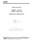
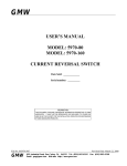
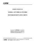
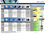
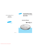
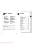
GMW
USER’S MANUAL
MODEL: 5971-160 Current Reversal Switch
PROPRIETARY
THIS DOCUMENT CONTAINS CONFIDENTIAL INFORMATION PROPRIETARY TO
GMW ASSOCIATES. IT MUST NOT BE REPRODUCED OR DISCLOSED TO
OTHERS OR USED IN ANY WAY EXCECPT FOR THE INSTALLATION,
OPERATION OR MAINTENANCE OF GMW ASSOCIATES PRODUCTS.
File No: 5971-160_Reversal_Switch_Users_Manual_Rev_A
GMW
Revision Date: 9 December, 2010
955 Industrial Road, San Carlos, CA 94070
Tel: (650)802-8292
E-mail: [email protected] Web: http://www.gmw.com
Fax: (650) 802-8298
TABLE OF CONTENTS
1 WARNINGS [ Refer to this section before operation ]
2.1 - Personal Safety
2.2 - Cable Connections
2.3 - Interlock Connections
Section 1
2
SPECIFICATIONS
Model 5971-160 General Specifications
Section 2
3
INSTALLATION
3.1 - Unpacking Instructions
3.2 - Rack Mounting
3.3 - Electrical Connections
Section 3
4 OPERATION
4.1 - System Description
4.1.1 - Front Panel
4.1.2 - Rear Panel
4.2 - Initial Operation
4.3 - External Control
4.4 - Computer Control
4.4.1 - USB 6251 DAQ
Section 4
5 SOFTWARE
Section 5
6
Section 6
MAINTENANCE
7 DRAWINGS
5971-160 Reversal Switch in a Bench Height Rack
General Assembly
5971-160 Reversal Switch Block Diagram
System Connection Diagram
System Connection Diagram
Internal Configuration Jumpers
SGA60-83 to 5971-160 Reversal Switch Cable
5971-160 Reversal Switch to 3473-70
SGA100-150 to 5971-160 Reversal Switch Cable
5971-160 Reversal Switch to 3474-140
Senis YM12 Signal & Power Cable
Section 7
11907-0154-0, Rev. A
11907-0153-0, Rev. C
13907-0008-0, Rev. A
13907-0009-0, Rev. A
13907-0009-1, Rev. A
1X907-0000-0, Rev. A
16907-0062-1, Rev. A
16907-0052-3, Rev. A
16907-0062-2, Rev. A
16907-0053-3, Rev. A
16912-0000-0, Rev. A
8
PHOTOGRAPHS
5971-160 Reversal Switch
Section 8
9
5971-160 Reversal Switch with GMW Electromagnets
8.1 - Table - GMW Electromagnets and appropriate DC Power Supplies
8.2 - Performance Data; Switch voltage vs. time
Section 9
10 Warranty
Section 1
WARNINGS
REFER TO WARNINGS BELOW BEFORE OPERATING THE 5971-160 REVERSAL
SWITCH
2.1 - Personal Safety
Never service alone. Do not perform service to the 5971-160 Reversal Switch and associated
DC Power Supply unless another person is present who is capable of rendering first aid.
The output from the model 5971-160 Reversal Switch and its DC Power Supply is potentially
lethal. It is capable of delivering high voltages at high current. Do not remove protective covers
or leave cable terminations exposed. Do not operate if terminals or cables are damaged.
2.2 - Current Connections
Special care should be taken to insure that the current terminations are secure and do not work
loose in operation. Local heating at the terminations can cause rapid oxidation leading to a high
contact resistance and high power dissipation at the terminals. If left unchecked this can cause
enough local heating to damage or destroy the current connection terminals.
2.3 - Interlocks
The 5971-160 Reversal Switch has interlock connections between the DC Power Supply and the
Electromagnet load. The interlocks must be connected for proper system functioning and
protection of the equipment, facility and to protect against personal injury. Attempting to
operate the system with the interlocks defeated is not recommended and will void the warranty.
Section 2
SPECIFICATIONS
Table 1. Model 5971-160 Current Reversal Switch Specifications
--------------------------------------------------------------------------------------------------------------------Electrical
Power Input (From DC Supply)
160A maximum
Recommended DC Power Supplies
Sorensen DLM40-75E
Sorensen SGA 60/83 60V, 83A
Sorensen SGA 100/150 100V, 150A
Sorensen SGA 160/31 160V, 31A
Sorensen SGA 160/62 160V, 62A
Sorensen SGA 160/156 160V, 156A
Sorensen SGA 200/75 200V, 75A
Power Input (Aux Power Supply)
115-220VAC, 50/60Hz, 2A
Note: While the power input module has a ‘selectable’ voltage range, it is not necessary
to select the range for any voltage between 115 - 220VAC.
200V, 160A maximum
Power Output
Switch Voltage Drop (at 20°C)
Switch Resistance at 150A (at 20°C)
< 440mV at 150A
< 3mΩ
Control Modes
Computer Control
National Instruments Multifunction DAQ, Model USB-6251
Current Control Resolution: 16 bits
Current & Voltage Monitor Resolution:16 bits
Digital read back of amplifier and magnet interlock status
Magnetic field read back resolution:16 bits
Manual Control
Manual control of the DC current via the DC Power Supply’s front panel controls
Manual control of the current polarity via the Current Reversal Switch’s front panel controls
Computer Control with external Analog Current Programming Input
National Instruments Multifunction DAQ, Model USB-6251
Current & Voltage Monitor Resolution:16 bits
Digital read back of amplifier and magnet interlock status
Magnetic field read back resolution:16 bits
User provided 0 - 10 volt analog control
Current Control Programming Voltage(1)
0 - 10 volt analog
Note (1): The Current output control may be via either the USB interface or the external analog
input, but not both.
Mechanical
5971-160 Current Reversal Switch
Form Factor
2U rack mount fully enclosed chassis
Overall Dimensions
482mm (19”) wide x 88.1mm (3.5”) high x 507mm (20”) deep
Weight 15.75 kg (35lbs)
5971-160 Current Reversal Switch & SGA Power Supply in Optima Rack
Overall Dimensions
560.5 (22”) wide x 1,058 (41.6”) high x 823 (32.4”) deep
Weight (with Sorensen SGA 60/83)
105.75kg (235lbs)
Weight (with Sorensen SGA 100/150)
115kg (250lbs)
Section 3
INSTALLATION
Caution: In many cases, the Reversal Switch and DC Power Supply will be pre-installed by
GMW into a 19” EIA equipment rack. If it is not, care should be taken during rack mounting to
avoid personal injury or damage to the equipment.
3.1 - Unpacking Instructions and Damage Inspection
3.1.1 - Systems Shipped with a GMW Supplied Rack:
1. Remove all eight of the lag bolts located at the lower edge of all the side panels of the
crate top cover.
2. Gently rock the crate top cover to work it loose from the shipping crate base.
3. Use one person on each side of the shipping crate grip the side panels of the crate top
cover. Lift the crate top cover high enough to clear top of the rack, walk the cover
sideways to a clear area and place it upon the floor.
4. Inspect the rack and its contents to ensure that no damage has occurred during
shipment. If any damage is evident report the damage in detail to the shipper for
claim and simultaneously notify GMW in case an assessment of the damage must be
made. If no damage is found, proceed with the unpacking and installation.
5. Cut the straps that secure the rack to the pallet base.
6. Remove the wood block at the bottom front edge of the rack.
7. Carefully slide the rack forward and off of the pallet base.
8. Unpack any other system components as per their instruction manuals.
3.1.2 - Systems Shipped without a GMW Supplied Rack:
1. Open the outer shipping carton by cutting the packing tape along the joints.
2. Remove the inner shipping carton by carefully lifting it out.
3. Open the inner shipping carton by cutting the packing tape along the joints.
4. Carefully lift the reversal switch clear of the shipping carton.
5. Inspect the reversal switch for any damage.
6. Retain all packing materials for future shipping needs.
3.2 - Rack Mounting
When rack mounting the 5971-160 Reversal Switch it is important to note that the vertical
mounting flanges alone are not strong enough to support the weight of the Reversal Switch.
Support angles on each side, beneath the 5971-160, must also be used. Failure to use adequate
support angles will result in equipment damage.
Take care when selecting a rack that it has enough depth to completely house the Reversal
Switch and DC Supply. The RC-351930 Bench Height Rack offered by GMW has an internal
depth of 762mm (30”). Typical installations would put the DC Supply at the bottom of the rack,
with the Reversal Switch just above, thus keeping the center of gravity as low as possible in the
rack. Other instrumentation may then be installed in to the upper sections of the rack.
Note: Telco style racks are NOT appropriate for the Reversal Switch and DC Supply.
3.3 - Electrical Connections
Even if the 5971-160 Reversal Switch was ordered as a complete system and assembled into a
rack by GMW, it is still recommended to follow and verify the following section as connections
may have loosened during shipment.
Refer to drawing 13907-0009-0, Rev. A for a detailed connection diagram.
3.3.1 - DC Supply and Electromagnet Connections
1. Connect the DC Supply to Switch Cable to the input +, input – and ground. This
cable provides the DC power, ground and interlock signals between the DC Power
Supply and the Switch. Ensure that ALL connections are tight, the polarity is correct
and the interlock cable is properly connected.
2. Connect the Reversal Switch to Electromagnet Cable output +, output – and ground.
This cable provides the current, ground and interlock signals between the Switch and
the Electromagnet. Again ensure that ALL connections are tight, the polarity is
correct and the interlock cable is properly connected.
It is critical that the DC Supply to the Reversal Switch and the Reversal Switch to
Electromagnet cables are connected correctly to the Reversal Switch Rear Panel
terminals. Incorrect connection may cause damage to the DC Power Supply or the
Reversal Switch.
3.3.2 – Reversal Switch Power
Connect the 115Vac or 220Vac power cord to the Reversal Switch. - This provides the
Reversal Switch with its required auxiliary power for the interlocks, computer interface,
magnetic field sensor and cooling fans.
3.3.1 - DC Supply Main Power
This procedure should be carried out by a qualified electrician.
1. Connect the DC Supply to the AC Mains service via an appropriate three-phase AC
power disconnect / breaker panel. For a GMW supported power supply, the
maximum input currents per phase are given below.
DC Power Supply
DLM40-75E, 3kW
SGA 60/83, 5kW
SGA 100/150, 15kW
SGA 160/156, 25kW
Voltage
180-264V
187-242V
187-242V
187-242V
Phases
3
3
3
3
Current per Phase
16A
21A
62A
103A
2. Ensure that the Electromagnet, Reversal Switch and DC Power Supply grounds are
connected. The DC Power Supply must be connected to the local service ground.
Section 4
SYSTEM DESCRIPTION
4.1 - System Description
A complete system would typically consist of an appropriate SGA series DC power supply, the
GMW 5971-160 Reversal Switch, a Senis magnetic field transducer, an electromagnet and an
appropriate computer and software or an external analog programming signal.
The DC Supply provides current to the electromagnet via the Reversal Switch, and is safety
interlocked by means of a relay contact in the Reversal Switch. The Supply’s output is enabled
on a closed contact, providing protection should the interlock cable be disconnected. Two
conditions will cause the interlock relay to open, shutting down the DC Supply’s output: An
internal fault detected in the Reversal Switch or a failure in the temperature or water flow
interlocks on the electromagnet.
The 5971-160 Current Reversal Switch is comprised of several sections: A proprietary MOSFET
switch and associated control electronics, a National Instruments USB-6251 Control with USB
interface and an auxiliary power supply all integrated into a single 19” rack mounting chassis.
Refer to drawing no. 13907-0008-0, Rev. A for an internal block diagram.
The auxiliary power supply provides power for the cooling fans, interlocks, control circuitry
and interface. It also provides -12V and +12V (400mA each) on the rear panel for an
optional external Senis Magnetic Field Transducer for magnetic field measurement and
closed-loop field control.
The interlock circuit for the magnet requires a ‘closed contact’ connection. Provision for
both the magnet over temperature and water flow is provided, and a failure of either one is
indicated on the front panel of the Reversal Switch. When using the NI USB-6251 DAQ,
this information is available via the computer control software. In the event of a magnet
interlock fault, the output of the DC Supply is inhibited.
The NI USB-6251 DAQ interface provides computer control and monitoring of the system.
It uses a 16-bit analog output (±10V) to provide the programming signal to the DC Supply.
The output voltage and current are monitored by two 16-bit input channels. Complete
Reversal switch and magnet interlock status is also monitored via its digital input channels.
When using an optional Senis Magnetic Field Transducer, the field is read back on a third
16-bit analog channel. For more information, please refer to the NI USB-6251 Manual and
section 4.5 in this manual.
4.1.1 - Front Panel
1.
2.
3.
4.
5.
6.
7.
8.
9.
10.
11.
12.
Power Switch
Power Indicator
Output Current Display
Output Voltage Display
Manual Current Polarity Control
Local Lockout Indicator
Power Supply Enabled Indicator
Forward Current Indicator
Reverse Current Indicator
Switch Over-Temperature Indicator
Magnet Over-Temperature Indicator
Magnet Water Flow Failure Indicator
4.1.2 - Rear Panel
1.
2.
3.
4.
5.
6.
7.
8.
9.
10.
11.
12.
13.
14.
AC Mains Input (Auxiliary Power Supply) - 115 - 220VAC, 2A
Fuse Holder / Voltage Selector
USB Port - Type B USB connection for computer control
Sensor Power - ± 12V power for Senis Magnetic Field Transducer
Sensor Input - Senis analog Magnetic Field Transducer input
Control Mode Switch - Selects either internal computer control or external analog
control input signal.
Analog Input - When selected, the Power Supply Full Scale output is proportional to a
0 to 10 volt control signal applied to this terminal
Magnet Interlock Connection
Power Supply Interlock Connection
Ground – Power Supply and Electromagnet GROUND connection
Output Positive to Magnet
Power Supply Negative Input
Output Negative to Magnet
Power Supply Positive Input
4.2 - Initial Operational Testing – Local Mode
Once the Power Supply, Reversal Switch and Electromagnet system are connected it is time to
perform initial system operational checks.
Start by switching on the Reversal Switch. The power indicator should illuminate, along with
the panel meters, the power supply enable and the polarity indicator as selected by the polarity
control. All interlock indicators should show green.
Temporally disconnect the Magnet Interlock connector from the Reversal Switch. The ‘Magnet
Temp’ and ‘Magnet Flow’ interlock indicators should illuminate red signifying a problem with
the magnet interlocks. Re-connect the Magnet Interlock connector. The interlock indicators on
the front panel should change to green.
Insure that the ‘Voltage’ and ‘Current’ controls on the DC Supply are turned down to their
minimum values and switch on the DC Power Supply. Slowly turn up the voltage and current
controls until about 5 amps is indicated on the DC Supply display. The panel meters on the
Reversal Switch should show similar values for voltage and current.
It is important to note that for normal operation, the DC Power Supply voltage be
set at Maximum. If this is not done, the DC Power Supply will be voltage limited
and full output current may not be achieved.
4.3 - External Control
To use the external control option, set the ‘Control Mode’ switch on the rear panel to ‘External’.
This disconnects the internal DAC and connects the DC Supply Current Input terminal to the
analog input. One thing to note is that it is still possible to use the internal DAQPad for
monitoring the Reversal switch even when using an external analog control signal.
Connect an analog voltage source to the Analog Input terminal. This source should be capable
of delivering voltages from 0V to +10V. The power supply current output is proportional to the
analog control input voltage.
4.4 - Computer Control
The 5971-160 is provided with a LabVIEW driver that allows basic control and monitoring of
the Reversal Switch and DC Power Supply. To use the external control option, set the ‘Control
Mode’ switch on the rear panel to ‘Internal’. This connects the internal DAC to the DC Power
Supply analog control input.
Start up the computer software and ensure that everything configured correctly. Please refer to
section 5 of this manual for more information.
4.4.1 - USB-6251 DAQ
The National Instruments USB-6251 DAQ together with GMW’s Magnet Control software
provides control and monitoring of the 5971-160 Reversal Switch. If GMW’s Magnet
Control software is not used, it is still possible to computer control the 5971-160 Reversal
Switch by writing custom software to communicate with the USB-6251. The table below
describes the channels used and their functions.
Signal
USB-6251 Connections
Type
Direction
Current Control Output
10V output proportional to 100%
current output
Current Control Common
Voltage Monitor
10V / 100% of the power supply’s
rated output voltage
Voltage Monitor Common
Current Monitor
10V / 100% of the power supply’s
rated output current
Current Monitor Common
Field Monitor +
Field Monitor Field Monitor Common
Analog
Single
Ended
Ground
Analog
Single
Ended
Analog
Analog
Single
Ended
Analog
Analog
Analog
Ground
- Reserved Switch Temp – Low = Okay
Magnet Flow – Low = Okay
Magnet Temperature – Low = Okay
P/S Enabled – High = Enabled
Polarity Status – High = Forward
Local Lockout – High = Remote
Polarity Control – High = Forward
Interlock Status Common
+5V Power
Digital
Digital
Digital
Digital
Digital
Digital
Digital
Digital
Ground
Power
6251 Terminal
Output
AO-0
Ground
Input
AO-GND
AI-0
Input
Input
AI-GND
AI-1
Input
Input
Input
Ground
AI-GND
AI-2
AI-10
AI-GND
Input
Input
Input
Input
Input
Input
Output
Output
-
P0.0
P0.1
P0.2
P0.3
P0.4
P0.5
P0.6
P0.7
DGND
+5V
Section 5
SOFTWARE
The 5971-160 Reversal Switch is provided with basic control and monitoring software. This
section covers the installation and basic operation of the software.
5.1 - Software Installation
Install the software packages in the order below. This should ensure that all components are
correctly installed and working.
1. Install the National Instruments software and driver package, NI-DAQmx, according to
the instructions in the National Instruments software manual.
2. Connect the Reversal Switch to the computer.
3. Using the National Instruments software, Measurement and Automation Explorer, verify
communication between the computer and the Reversal Switch.
4. Install the GMW Reversal Switch software.
The GMW supplied software allows basic control and monitoring. There are two options
when installing the software. The first is a basic run-time version that does not allow
modification of the software. The second option is a set of virtual instruments (VIs) that
may be modified to suite a custom application. Note that the ability to use the VI version
requires the purchase of the complete National Instruments LabVIEW software package.
5.1.1 - Installing the Run Time software version
1. Insert the GMW supplied software disc in to the CD or DVD drive.
2. Run the setup.exe located in the directory \Installer\Volume.
This will install both the runtime and source VIs and by default, the installer will
place the files in the directory c:\program files\GMW 5971 Reversal Switch\. You
may change this at the time of installation.
3. After the setup has completed, read the readme file for any last minute changes or
notes.
5.2 - Operating the Reversal Switch using the GMW Software
Once the software is installed, it will be possible to control and monitor the Reversal Switch
using the supplied software.
5.2.1 - Running the software
1. The runtime version is accessed via the start menu:
Start > All Programs > GMW 5971 Reversal Switch V1_0> GMW Reversal Switch
5971-160.exe
2. The source VIs are located in the directory c:\program files\GMW 5971 Reversal
Switch V1_0\Source VI\. Note that LabVIEW 8.6.1 or later is required to run, view
or modify the source VIs.
5.2.2 - Software Configuration
Upon the first run of the software, a simple configuration screen will be presented. Select
the DC Power Supply type from the provided list. If the power supply that is being used
is not listed, enter the maximum voltage and current of the DC Power Supply that you
have. Then select the address of the USB-6251 DAQ from the list. You may also enter
the default directory to be used for storing data generated from the data logger.
Save and exit the configuration screen.
Configuration Screen
5.2.3 - Basic Operation
Once configured, the normal operation screen will be presented. This screen provides
control of current and polarity and monitoring of the DC Power Supply’s output voltage
and current. It also provides status read back of the Reversal Switch and Electromagnet
interlock status.
It is important to note that when operating remotely, the DC Power Supply front
panel controls be set as follows: Voltage to Maximum, Current to zero. If this is
not done, the DC Power Supply will be voltage limited and full output current
may not be achieved.
5.2.4 - Local / Remote
The Reversal Switch software defaults to local operation. In order to control the
Reversal Switch it must first be placed into the ‘Remote’ mode. This is done by
clicking on the Local / Remote’ Control. This control will change its state depending
on what mode it is in. The two states are:
‘Local’ - The control is green and displays the legend ‘Push for Remote’
‘Remote’ - The control is yellow and displays the legend ‘Push for Local’
Selecting Local or Remote
5.2.5 - Setting the output current
The output current is simply set by entering the desired output current in the current
control box.
Setting the Output Current
5.2.6 - Selecting the Reversal Switch polarity
To change the Reversal Switch polarity, simply click on the polarity control toggle.
The Reversal Switch will then inhibit the DC Power Supply’s output, wait for the
voltage to drop to a safe level, change polarity and then re-enable the DC Power
Supply’s output.
The switching time will depend on the configuration of the load. Switching
times may approach 20 seconds.
Changing Polarity
5.2.7 - Timed Switching
The software has the ability to automatically switch at a rate chosen by the operator.
To use the timed switching function follow the procedure below.
1. Push the ‘Enable Timer’ button.
2. Enter the desired time switching interval in seconds. Note that 30 seconds is the
minimum interval.
Timer Enable and Interval
3. Press the ‘Start’ button.
Note that while timed switching is enabled, the regular forward / reverse control is
disabled..
5.2.8 - Data Logging
There are a few things to set up in order to use the data logger:
1. Push the ‘Create Log File’ button. This will open a dialog box that will prompt
for the file name of the log file. If the file exists, it will prompt for confirmation
to over write the existing file.
2. Enter a log file sample interval (in mili-seconds). Set to 0 to log every sample.
Note at this time, data is NOT being logged.
3. To start the logging, click on the green ‘Start Logging’ button. The button will
then change to a red ‘Pause Logging’ Button.
4. To stop or pause the logging, click on the red ‘Pause Logging’ button. The button
will change back to the green ‘Start Logging’ button.
5. To close the log file, click on the ‘Close Log File’ button.
Creating the Log File
5.2.9 - Status Read Back
This software will read back the Reversal Switch status regardless of its Local /
Remote status. The status read back consists of three interlock indicators and the
general status indicators.
If any one of the interlock conditions exists, the corresponding indicator will flash on
the screen and the DC Power Supply’s output will be disabled.
Interlock and Status Indicators
Section 6
MAINTENANCE
The 5971-160 Current Reversal Switch should operate for many years without any trouble
provided that the following basic maintenance points are observed. Always remember that the
AC power should be disconnected before performing any maintenance procedure. The 5971160 may generate lethal voltages and must not be operated with damaged components,
protective covers or cable insulation. For more information, please refer to Section 2, Warnings
1. Electrical Connections: Ensure that all electrical connections are clean and tight. Ensure that
the insulation of all electrical cables is undamaged and repair or replace if necessary. All
electrical termination covers must be in place and firmly secured.
A corroded and / or loose high current connection will cause a voltage drop across the
connection. A drop of 0.1V at 160A results in 16W being dissipated at the connection. The
connection will increase in temperature which will result in oxidation or the connection, a
higher resistance and a further increase in power dissipation. If this situation is left
uncorrected the cable and Reversal Switch insulation will melt and possibly the copper
connections will melt as well. Not only will the Reversal Switch and nearby equipment be
damaged, but there is the possibility for fire.
2. Warning Labels: Ensure that all protective covers on the system and the magnet are in place.
There are warning labels on all removable covers.
3. Cooling: Check that the fans are clean and free of blockage. Ensure that the fans are
operating at full efficiency.
4. Cleaning: To clean wipe the case with a soft cloth with a mild detergent or plain water. Do
not use any solvents as they may damage the finish.
Section 7
DRAWINGS
8
5
4
3
2
REVISION HISTORY
DESCRIPTION
Release
Update Front Panel
Update Rear Panel Text
DATE
10/20/2009
02/23/2010
11/22/2010
APPROVED
Michael E. Duffy
Michael E. Duffy
Michael E. Duffy
1
A
B
88.1
8
7
Weight:
15.75kg (35Lbs)
Power Input:
115-220VAC, 50/60 Hz, 2A
Max Switched Power: 200V, 160A
M. Duffy
DO NOT SCALE
FROM DRAWING
20 Oct, 2009
± 0.1
±0.5
1.6
2
THIRD ANGLE PROJECTION
63
±1
±0.3
±.5
X
FINISH
±.03
X.X
±0.03
mm
DEG.
± .01
±.06
X.XX
±.005
X.XXX
Date
ENGINEERING
M. Duffy
INCHES
DIMENSIONS & TOLERANCES
UNLESS OTHERWISE SPECIFIED
LINEAR
Date
Date
20 Oct, 2009
20 Oct, 2009
CHECK
M. Duffy
DRAWING No.
SCALE: NTS
WT: -
kg
A2 11907-0153-0
SIZE
SHEET: -
1
OF: -
C
REV
5971-160 MOSFET Reversing
Switch - General Assembly
TITLE
955 Industrial Road, San Carlos, CA 94070
Tel: (650) 802-8292. Fax: (650) 802-8298
GMW Associates
A
B
C
DRAWN
3
C
REV
A
B
C
D
ZONE
D
507
4
E
6
5
E
482
6
F
7
F
THIS DRAWING CONTAINS CONFIDENTIAL
INFORMATION PROPRIETARY TO GMW INC. IT MUST
NOT BE REPRODUCED OR DISCLOSED TO OTHERS OR
USED IN ANY OTHER WAY, IN WHOLE OR IN PART
EXCEPT AS AUTHORIZED IN WRITING BY GMW INC.
PROPRIETARY
Section 8
PHOTOGRAPHS
5971-160 Front View
5971-160 Rear View
Section 9
5971-160 with GMW ELECTROMAGNETS
9.1 Table - GMW Electromagnets and appropriate DC Power Supplies for use with the
5971-160 Current Reversal Switch
GMW Electromagnet
5403, 5403EG, 5403FC, 5403AC
5404
3472-50, 3472-70
3473-50, 3473-70
3474, 5501
5414
5451
9.2 Performance Data
Peak DC Power
Ametek - Sorenson Power Supply
70A, 33V, 2.3kW
70A, 160V, 11.2kW
70A, 50V, 3.5kW
70A, 59V, 4.1kW
140A, 76V, 10.6kW
140A, 116V, 16.2kW
70A, 25V, 1.75kW
DLM40-75E, 40V, 75A, 3kW
SGA 200/75, 200V, 75A, 15kW
SGA 60/83, 60V, 83A, 5kW
SGA 60/83, 60V, 83A, 5kW
SGA100/150, 100V, 150A, 15kW
SGA160/150, 160V, 150A, 25kW
DLM40-75E, 40V, 75A, 3kW
GMW Associates
5971‐160 Reversing Switch Performance Plot
Contract No:
Customer:
9625 Army Research Lab
5971‐160 Serial No:
Power Supply: Magnet Model:
Pole:
Field Meter:
Note:
02
P83C‐100150
3474 50mm
Senis YM12‐5‐5‐5T
Page:
1 of 1
Serial No:
Serial No:
Gap:
Serial No:
Date:
Engr:
2 Dec, 2010
M. Duffy
0250A00730
105 30mm
24‐07
Set Current: 50A, Timed Switching every 30 seconds.
Current (A)
Voltage (V)
80
2
60
1.5
40
1
20
0.5
0
0
‐20
‐0.5
‐40
‐1
‐60
‐1.5
‐80
‐2
13:18:01.152 13:18:09.792 13:18:18.432 13:18:27.072 13:18:35.712 13:18:44.352 13:18:52.992 13:19:01.632
Time
Field (Tesla)
Current & Voltage
Field (T)
GMW Associates
5971‐160 Reversing Switch Performance Plot
Contract No:
Customer:
9625 Army Research Lab
5971‐160 Serial No:
Power Supply: Magnet Model:
Pole:
Field Meter:
Note:
02
P83C‐100150
3474 50mm
Senis YM12‐5‐5‐5T
Page:
1 of 1
Serial No:
Serial No:
Gap:
Serial No:
Date:
Engr:
2 Dec, 2010
M. Duffy
0250A00730
105 30mm
24‐07
Set Current: 150A, Timed Switching every 30 seconds.
Current (A)
Voltage (V)
Field (T)
175
3
150
125
2
100
75
Current & Voltage
25
0
0
‐25
‐50
‐1
‐75
‐100
‐2
‐125
‐150
‐3
‐175
13:29:45.312 13:29:53.952 13:30:02.592 13:30:11.232 13:30:19.872 13:30:28.512 13:30:37.152 13:30:45.792
Time
Field (Tesla)
1
50
GMW Associates
5971‐160 Reversing Switch Performance Plot
Contract No:
Customer:
9625 Army Research Lab
5971‐160 Serial No:
Power Supply: Magnet Model:
Pole:
Field Meter:
Note:
02
P83C‐100150
3473
100mm
Senis YM12‐5‐5‐5T
Page:
1 of 1
Serial No:
Serial No:
Gap:
Serial No:
Date:
Engr:
7 Dec, 2010
M. Duffy
0250A00730
153
25mm
24‐07
Set Current: 70A, Timed Switching every 30 seconds.
Current (A)
Voltage (V)
Field (T)
150
2.5
125
2
100
1.5
75
1
0.5
25
0
0
‐25
‐0.5
‐50
‐1
‐75
‐1.5
‐100
‐2
‐125
‐150
‐2.5
14:52:46.877 14:52:55.517 14:53:04.157 14:53:12.797 14:53:21.437 14:53:30.077 14:53:38.717 14:53:47.357
Time
Field (Tesla)
Current & Voltage
50
GMW Associates
5971‐160 Reversing Switch Performance Plot
Contract No:
Customer:
9625 Army Research Lab
5971‐160 Serial No:
Power Supply: Magnet Model:
Pole:
Field Meter:
Note:
Page:
02
P83C‐100150
5403
76mm
Senis YM12‐5‐5‐5T
1 of 1
Serial No:
Serial No:
Gap:
Serial No:
Date:
Engr:
7 Dec, 2010
M. Duffy
0250A00730
352
54mm
24‐07
Set Current: 50A, Timed Switching every 30 seconds.
Current (A)
Voltage (V)
Field (T)
80
1
0.8
60
0.6
40
20
0.2
0
0
‐0.2
‐20
‐0.4
‐40
‐0.6
‐60
‐0.8
‐80
10:59:44.160
‐1
10:59:52.800
11:00:01.440
11:00:10.080
Time
11:00:18.720
11:00:27.360
Field (Tesla)
Current & Voltage
0.4
GMW
LABORATORY ELECTROMAGNET SYSTEMS
WARRANTY DECEMBER 2010
GMW Associates warrants that all Electromagnets, Laboratory Electromagnet Systems and
Electromagnet System Components supplied by GMW Associates will be free of defects in materials or
workmanship for a period of 12 months from the date of installation or 15 months from the date of
shipment whichever is the shorter.
Within this period GMW Associates will repair or replace defective parts free of charge either at the
end user’s site or at GMW Associates location at GMW choice.
GMW Associates will reimburse or pay the lowest two way freight charges on items returned to GMW
Associates or our authorized agent provided prior authorization for shipment has been given by GMW
Associates.
This warranty shall not apply to any equipment which our inspection shows to have become defective
due to mishandling, misuse, improper maintenance or any other damage not generally acceptable for
equipment of a similar type.
GMW Associates reserves the right to make changes in product or system design without incurring any
obligation to modify previously delivered equipment.
The foregoing is the full extent of the GMW Associates warranty. No other warranty is expressed or
implied. In no event shall GMW Associates be liable for damage arising from late delivery or misuse
of the equipment. GMW Associates makes no warranty of the fitness of the equipment for the intended
end-use other than the equipment meets the written specifications presented to the purchaser by GMW
Associates.
If any defect or fault in the equipment is discovered the end-user should notify GMW Associates of the
problem including details of Model numbers and serial numbers. GMW Associates will either make
arrangements for service by the end-user or GMW Associates, or give authorization for return shipment
to GMW Associates.
All return shipments must be made according to GMW Associates instructions with adequate
packaging and documentation identifying the shipment including the GMW Associates Return Material
Authorization (RMA) number. GMW Associates will not accept responsibility for equipment damaged
in return shipment and thus all shipments should be properly packed and adequately insured by the
customer.
File Name: 8X907-0001-0_Rev_B_LabMag_Warranty
955 Industrial Road, San Carlos, CA 94070 Tel (650) 802-8292 Fax (650) 802-8298 Email [email protected]