1
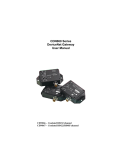
TM
MicroNode I/O
DeviceNet DIDO
User Manual
Controls Group
134 W Rio Robles Drive
San Jose, CA 95134
Main: 408.750.0300
Fax: 408.750.2990
Rev. 03
11/05
Page 1 of 31
© MKS Instruments CIT Products 2005, All rights reserved
MicroNode I/OTM DeviceNet DIDO User Manual
Copyright
This manual and the software described in it are copyrighted with all
rights reserved. Under the copyright laws, this manual and software may
not be copied, in whole or part, without the prior written consent of MKS
Instruments. The same proprietary and copyright notices must be affixed
to any permitted copies as were affixed to the original. This exception
does not allow copies to be made for others whether or not sold, but all of
the materials purchased may be sold, given, or loaned to another person.
Under the law, copying includes translating into another language or
format.
© MKS Instruments - Controls Group, 2011
134 W Rio Robles Drive
San Jose, CA 95134
Preface
About this manual
This manual is designed to serve as a guideline for the installation, setup,
operation and basic maintenance of the MicroNode device. The
information contained within this manual, including product specifications,
is subject to change without notice. Please observe all safety precautions
and use appropriate procedures when handling the MicroNode product
and its related software.
Export Regulation
MKS Products provided subject to the US Export Regulations. Diversion or
transfer contrary to U.S. law is prohibited.
Page 2 of 31
© MKS Instruments CIT Products 2005, All rights reserved
Table of Contents
1
GENERAL INFORMATION ..................................................................................................5
1.1
2
CONVENTIONS USED IN THIS USER MANUAL .................................................................................... 5
INSTALLATION AND SETUP ..............................................................................................6
2.1
SHIPPING BOX CONTENTS.............................................................................................................. 6
2.2
MICRONODE HARDWARE DESCRIPTION .......................................................................................... 6
2.3
INSTALLATION ................................................................................................................................ 6
2.4
WIRING ......................................................................................................................................... 7
2.5
ROTARY SWITCHES ....................................................................................................................... 7
2.6
CONFIGURATION ............................................................................................................................ 8
2.6.1 Power Supply Wiring............................................................................................................... 8
2.6.2 I/O Wiring ................................................................................................................................ 8
3
QUICK-START......................................................................................................................9
3.1
3.2
3.3
4
HARDWARE SETUP ........................................................................................................................ 9
CONFIGURING THE MICRONODE ................................................................................................... 10
ENABLING THE I/O ....................................................................................................................... 10
THEORY OF OPERATION .................................................................................................12
4.1
DEVICENET INTERFACE ............................................................................................................... 12
4.1.1 Digital I/O .............................................................................................................................. 13
5
MICRONODE CONFIGURATION.......................................................................................14
5.1
CONFIGURE DEVICENET INTERFACE ............................................................................................. 14
5.1.1 DeviceNet Baud Rate Switch................................................................................................ 14
5.1.2 MAC ID Switches .................................................................................................................. 14
5.2
POWER UP .................................................................................................................................. 14
5.2.1 DeviceNet Status LEDs ........................................................................................................ 15
5.3
REGISTER EDS FILE.................................................................................................................... 15
5.4
POLLED I/O CONFIGURATION ....................................................................................................... 15
6
DEVICENET OBJECT MODEL ..........................................................................................16
6.1
IDENTITY OBJECT CLASS CODE: 01 (0X01)................................................................................... 16
6.1.1 Revision – Attribute 4............................................................................................................ 17
6.1.2 Status – Attribute 5 ............................................................................................................... 17
6.1.3 Serial Number – Attribute 6 .................................................................................................. 18
6.2
ROUTER OBJECT CLASS CODE: 02 (0X02) ................................................................................... 18
6.3
DEVICENET OBJECT CLASS CODE: 03 (0X03) .............................................................................. 19
6.3.1 MACID – Attribute 1 .............................................................................................................. 19
6.3.2 Baud Rate – Attribute 2 ........................................................................................................ 19
6.3.3 Bus Off Interrupt – Attribute 3 ............................................................................................... 20
6.3.4 Bus Off Counter – Attribute 4................................................................................................ 20
6.3.5 Allocation Information – Attribute 5....................................................................................... 20
6.4
ASSEMBLY OBJECT CLASS CODE: 04 (0X04) ................................................................................ 20
6.4.1 Default Assembly Object Instance 1 and 2 Structure ........................................................... 21
CONNECTION OBJECT CLASS CODE: 05 (0X05)...................................................................................... 22
6.4.2 State – Attribute 1 .............................................................................................................. 23
6.4.3 Connection ID's – Attributes 4 and 5 .................................................................................... 23
6.4.4 Production and Consumed Sizes – Attributes 7 and 8 ......................................................... 23
6.4.5 Watch Dog Timeout Activity – Attribute 12 ........................................................................... 24
6.5
DISCRETE INPUT POINT OBJECT CLASS CODE: 08 (0X08) ............................................................. 24
6.5.1 Input State – Attribute 3 ........................................................................................................ 24
6.5.2 Status – Attribute 4 ............................................................................................................... 25
6.6
DISCRETE OUTPUT POINT OBJECT CLASS CODE: 09 (0X09).......................................................... 25
6.6.1 Output State – Attribute 3 ..................................................................................................... 25
6.6.2 Status – Attribute 4 ............................................................................................................... 26
Page 3 of 31
© MKS Instruments CIT Products 2005, All rights reserved
MicroNode I/OTM DeviceNet DIDO User Manual
6.7
S-DEVICE SUPERVISOR OBJECT CLASS CODE: 48 (0X30) ............................................................. 26
6.7.1 Change Mode Request ......................................................................................................... 27
6.7.2 Jump To Boot Loader Request............................................................................................. 27
6.7.3 Software Revision Level – Attribute 7................................................................................... 27
6.7.4 Hardware Revision Level – Attribute 8 ................................................................................. 28
6.7.5 Device Status – Attribute 11 ................................................................................................. 28
6.7.6 Exception Status – Attribute 12 ............................................................................................ 28
6.8
CONFIGURATION OBJECT CLASS CODE: 100 (0X64) ..................................................................... 28
6.8.1 Reset Service........................................................................................................................ 29
7
APPENDIX A - SPECIFICATIONS .....................................................................................30
8
WARRANTY .......................................................................................................................31
Page 4 of 31
© MKS Instruments CIT Products 2005, All rights reserved
MicroNode I/OTM DeviceNet DIDO User Manual
1 General Information
The MicroNode I/O™ product line provides high-density, compact and economical I/O solutions
for popular Fieldbus Networks. The MicroNode DIDO provides up to 16 digital I/O point to the
DeviceNet™ network. The MicroNode package provides flexible side or foot mounting and easy
access to I/O through a standard 37-pin D-Sub connector. All physical and object model
features are ODVA Semi SIG compliant.
AS00120-01
AS00121-01
AS00122-01
AS00123-01
MicroNode I/O, DeviceNet, 16 DIDO, sink, side
MicroNode I/O, DeviceNet, 16 DIDO, sink, front
MicroNode I/O, DeviceNet, 16 DIDO, source, side
MicroNode I/O, DeviceNet, 16 DIDO, source, front
1.1 Conventions used in this User Manual
Warning
The WARNING sign denotes a hazard to personnel. It calls attention to a
procedure, practice, condition, or the like, which, if not correctly
performed or adhered to, could result in injury to personnel.
Caution
The CAUTION sign higlights information that is important to the safe
operation of the unit, or to the integrity of your files. .
Note
THE NOTE SIGN DENOTES IMPORTANT INFORMATION. IT CALLS
ATTENTION TO A PROCEDURE, PRACTICE, CONDITION, OR THE
LIKE, WHICH IS ESSENTIAL TO HIGHLIGHT.
On screen buttons or menu items appear in bold and cursive.
Example: Click OK to save the settings.
Keyboard keys appear in brackets.
Example: [ENTER] and [CTRL]
Pages with additional information about a specific topic are cross-referenced within the
text.
Example: (See page xxx)
Page 5 of 31
© MKS Instruments CIT Products 2005, All rights reserved
MicroNode I/OTM DeviceNet DIDO User Manual
2 Installation and Setup
2.1 Shipping Box Contents
•
MicroNode Product
2.2 MicroNode Hardware Description
I/O 37 Pin DSUB
See I/O Table
Module Status LED (MOD)
STATE
DESCRIPTION
OFF
RED BLINK
RED
GREEN BLINK
GREEN
No power
Configuration error
Unrecoverable error
Not defined
Normal operation
DeviceNet Status LED (NET)
MicroNode I/O
STATE
DESCRIPTION
OFF
RED BLINK
RED
GREEN BLINK
GREEN
No power
Configuration error
Unrecoverable error
Not allocated to a master
Allocated to a master
2
DeviceNet Data Rate
Rotary Switch
DeviceNet Address
Rotary Switches
1
5
3
4
DeviceNet Channel
(male 5-pin micro connector)
PIN
SIGNAL
1
2
3
4
5
SHIELD
V+
VCAN H
CAN L
2.3 Installation
Mount the MicroNode on a horizontal or vertical surface, in a suitable location or enclosure for
your application. Provide sufficient clearance and airflow to maintain 0°C to 55°C ambient
operating temperature range. Fasten the unit to the mounting surface using four screws (not
provided) in the 4mm wide mounting holes.
Page 6 of 31
© MKS Instruments CIT Products 2005, All rights reserved
MicroNode I/OTM DeviceNet DIDO User Manual
Height of 31mm,
not including D-Sub 37 connector
Note
ALL DIMENSIONS ARE METRIC
2.4 Wiring
The MicroNode requires two connections – one to the DeviceNet network (male 5-pin micro
connector) and one to the 37-pin D-SUB. DeviceNet™ and I/O cables are available from a
variety of industrial sources. See table below for orderable I/O mating connectors.
Description
Manufacture Part Number
37-pin D-SUB Receptacle (solder cup)
Mouser
523-17D-C37S
37-pin D-SUB Metal Hood
Mouser
523-17-1727-2
Follow all applicable electrical codes in your area when mounting
and wiring any electrical device.
Warning
2.5 Rotary Switches
Set the rotary switches to the desired settings. Use a small slotted screwdriver to rotate the
switches. Align the indicator arrow to the desired setting, as shown below.
switch position
switch indicator
switch screw slot
Page 7 of 31
© MKS Instruments CIT Products 2005, All rights reserved
MicroNode I/OTM DeviceNet DIDO User Manual
Each rotary switch parameter has a PGM option. Setting a switch to PGM allows the parameter
to be remotely set over DeviceNet™. However, it must first be initialized. To initialize, set the
switch to desired value and power the unit . The new settings are saved in memory. Power
down and change switch to PGM mode.
2.6 Configuration
Rotary switches and software parameters are used to configure the MicroNode’s DeviceNet
Interface and I/O functions. The MicroNode is configured over DeviceNet. Use your DeviceNet
configuration program and the MicroNode’s electronic data sheet (EDS) file to set the software
parameters over DeviceNet.
2.6.1 Power Supply Wiring
All network circuits are powered from DeviceNet. Select your DeviceNet cables and power
supply so that it can provide sufficient current for all networked devices at their peak operating
power. For Digital I/O power, the 24-Volt power is supplied externally from the I/O Connector.
To power the Digital I/O from the DeviceNet power, you can remove the top cover, and add
jumpers to JP4 and JP5, pins 1&2. This connection is fused at 2A for 24VDC supply to the I/O
connector. Make sure that an additional power supply is not connected, as damage to the
DeviceNet network may occur.
2.6.2 I/O Wiring
The MicroNode has a male 37-pin D-Sub for I/O. The pinout is shown in the following table.
I/O Pinout
DIDO Model Connector
Pin Signal Pin Signal
1
+24V IN 20 24V GND
2
DIO9
21 24V GND
3
DIO8
22 +24V IN
4 24V GND 23 +24V IN
5
+24V IN 24
6
DIO7
25 24V GND
7
DIO6
26 +24V IN
8 24V GND 27
DIO15
9
+24V IN 28
DIO14
10
DIO5
29 24V GND
11
DIO4
30 +24V IN
12 24V GND 31
DIO13
13 +24V IN 32
DIO12
14
DIO3
33 24V GND
15
DIO2
34 +24V IN
16 24V GND 35
DIO11
17 +24V IN 36
DIO10
18
DIO1
37 24V GND
19
DIO0
Page 8 of 31
© MKS Instruments CIT Products 2005, All rights reserved
MicroNode I/OTM DeviceNet DIDO User Manual
3 Quick-Start
This chapter describes the setup for a simple system using a DeviceNet™ master and a
MicroNode module. Before beginning, a basic understanding of DeviceNet is recommended.
Experience using explicit and poll transactions from the software provided with your DeviceNet
master is essential. For more information on generating explicit and poll messages consult the
DeviceNet master’s user’s guide.
3.1 Hardware Setup
Setup a connection between a DeviceNet master and the MicroNode.
Required Hardware:
•
•
•
DeviceNet cable
DeviceNet master
Power supply
Sample Input Connection
Current Sinking
COM
Contact
Closure
DIO
Point
Current Sourcing
+24V
Contact
Closure
DIO
Point
Sample Output Connection
Current Sinking
22k
+24V
LED
R
DIO
Point
Current Sourcing
22k
DIO
Point
LED
R
COM
Page 9 of 31
© MKS Instruments CIT Products 2005, All rights reserved
MicroNode I/OTM DeviceNet DIDO User Manual
3.2 Configuring the MicroNode
The major steps for configuring the MicroNode include setting up the DeviceNet I/O Objects.
Configure the MicroNode switches as follows:
• MACID MSD to 0
• MACID LSD to 1
• DeviceNet Data rate to 500K
Once all of the hardware is setup and powered, make sure that the master can allocate both poll
and explicit connections to the unit. Once allocated, both the NET and MOD LED will be solid
green.
Warning At this point, if the network and module LEDs on both the master
and MicroNode are not solid green, do not proceed. Ensure the
master baud rate matches the switch on the MicroNode, and that
the MicroNode has a node address that is not used by another node
on the network.
Out of the box the MicroNode is pre-configured to control digital I/O. Refer to chapter 5 create a
customer I/O configuration.
3.3 Enabling the I/O
Reading Input Points
Set Explicit Message data as shown. Set Instance value for desired input point (1-16). Turn on an Input,
and verify the LED has turned on. Read the input through the Explicit Message below.
Setting Output Points
Set Explicit Message data as shown. Set Instance value for desired output point (1-16). To turn on the
output point, set Service Data to “03 01” and observer the LED has turned on. To turn off a point, set
Service Data to “03 00”.
Page 10 of 31
© MKS Instruments CIT Products 2005, All rights reserved
MicroNode I/OTM DeviceNet DIDO User Manual
Reading Output Points
Use same method as reading input points. Change Class to 9.
Note
The Instance for an I/O point is numbered 1 – 16, where as the I/O is
labeled 0 – 15.
Page 11 of 31
© MKS Instruments CIT Products 2005, All rights reserved
MicroNode I/OTM DeviceNet DIDO User Manual
4 Theory of Operation
This chapter describes how the MicroNode operates. Working knowledge of DeviceNet is
required before continuing. The Open DeviceNet Vendors Association (www.odva.com) is a
good source for general DeviceNet information.
4.1 DeviceNet Interface
The DeviceNet Specification defines an Object Model that consists of Objects and Attributes.
An Object is a predefined software process, and an Object Attribute is a data value used or
created by that process. An Object can have multiple Instances, or the same process operating
with different sets of Attributes or data values. For the purpose of this document, an Object
Instance is an independent program or process, and its Attributes are configuration parameters
and data values that are unique to that specific Object Instance.
The MicroNode has eleven different Object Classes, or types. Five are standard objects
defined by the DeviceNet Specification (Identity, Router, DeviceNet, Assembly, Connection).
Other specific objects defined for the MicroNode include (Discrete Digital Input, Discrete Digital
Output, eSupervisory Object, User Defined Configuration Object).
The MicroNode operates as a DeviceNet slave. It supports Explicit Messages and Polled I/O
Messages of the predefined master/slave connection set. The Explicit Unconnected Message
Manager (UCMM) is not supported. The MicroNode™ will be a Group 2 Only Slave device. It
will support Polled I/O and Explicit Messaging. The DeviceNet interface complies with the
DeviceNet Physical Layer specification.
NET /MO DULE
LEDS
DIG IT AL IN LED INDICAT IO N
POW ER
INPUT :11~36V
OUTPUT:
5V FO R TRNSCVR
5V ISLO ATED
FO R DIGITAL
SECTIO N
SERIAL DATA +CO NTRO L
FOR DOUT DRIVERS
ISO LAT IO N
ON BOARD BAUD RATE
RO TARY SW ITCH
SINK/SOURCE
DRIVERS
DIG ITAL IN /O UT
J1 INPUT/OUTPUT
ON BOARD MAC ID
ROTARY SW ITCHS
DIGITAL IN/O UT FEEDBACK
P1 DEVICENET
CAN
TRANSCIVER
ISOLATION
DNET
CO NT ROLLER
+PLD
+MEMO RY
Page 12 of 31
© MKS Instruments CIT Products 2005, All rights reserved
MicroNode I/OTM DeviceNet DIDO User Manual
4.1.1 Digital I/O
The Digital I/O is optically coupled from the processor. The individual outputs will support up to 200
mA loads per channel. Based on package dissipation the maximum fully loaded output current is
100 mA (8 outputs) at 50 oC ambient. Each output is thermally protected for short circuit (500 mA
typically) and includes under voltage protection. The output Fault State is accessible through
software. External Schottky diodes are provided for output transient protection and each I/O point is
protected with a self-resetting poly fuse rated for 200 mA. Outputs default to the OFF condition
during power up and processor reset conditions.
The digital output read back signals (inputs) are active low, with current limiting resistors setting the
short circuit current to 3 mA at 24 Vdc. Each input circuit includes an indicator LED in series with
the detection opto-coupler. Both the detection opto-coupler and the indicator LED are protected
with a shunt diode against reverse voltage breakdown.
The digital I/O circuitry is powered from an external +24 Vdc power source unless jumpers are
placed internally on JP4 and JP5. When the Jumpers are installed, the +24 Vdc is supplied by
the CAN Bus+ and Bus- pins. By default the +24 Vdc must be supplied externally on the I/O
connector.
Digital I/O Schematic
Page 13 of 31
© MKS Instruments CIT Products 2005, All rights reserved
MicroNode I/OTM DeviceNet DIDO User Manual
5 MicroNode Configuration
This chapter describes how to configure and operate the MicroNode. The MicroNode is
configured by reading and writing attribute values over the DeviceNet interface. There are a
variety of DeviceNet configuration tools available.
Simple configuration tools use
GET_ATTRIBUTE and SET_ATTRIBUTE explicit message commands to read and write
attribute values, addressing each attribute by its Object, Instance, and Attribute numbers. More
sophisticated configuration tools use EDS files to simplify attribute configuration.
5.1 Configure DeviceNet Interface
The DeviceNet Baud Rate and MAC ID Address are set using the rotary switches. Configure
switches before connecting to the DeviceNet network. There is either a small triangular
indicator or white indicator on the switch. Use a small screwdriver to align that indicator with the
desired setting.
5.1.1 DeviceNet Baud Rate Switch
Valid settings are 125K, 250K, 500K, or PGM. When PGM is selected, the MicroNode™ uses
the baud rate saved in its retentive memory. To save a valid baud rate in memory, set the
switch to the desired baud rate and power the MicroNode™ for a few seconds. Power down
and set the switch to PGM. You may also write to the DeviceNet Object Baud Rate attribute.
POSITION
0
1
2
SETTING
125 Kbps
250 Kbps
500 Kbps
5.1.2 MAC ID Switches
The two MAC ID switches represent decimal numbers from 00 to 99. The LSB switch selects
the Ones digit and the MSB switch selects the Tens digit. Valid MAC IDs are 00 to 63. Setting
a MAC ID address greater than 63 forces the to use the MAC ID saved in retentive memory. To
save a valid MAC ID in memory, set the switches to the desired MAC ID and power the
MicroNode™ for a few seconds. Power down and set the switches to value greater than 63.
You may also write to the DeviceNet Object MAC ID attribute.
MSB
0
1
2
3
4
5
6
LSB
0 to 9
0 to 9
0 to 9
0 to 9
0 to 9
0 to 9
0 to 3
Address
00 to 09
10 to 19
20 to 29
30 to 39
40 to 49
50 to 59
60 to 63
MSB
6
7
8
9
LSB
4 to 9
0 to 3
0 to 9
0 to 9
Address
stored address
stored address
stored address
stored address
5.2 Power Up
Connect the DeviceNet network cable and I/O cable to power the MicroNode.
Page 14 of 31
© MKS Instruments CIT Products 2005, All rights reserved
MicroNode I/OTM DeviceNet DIDO User Manual
5.2.1 DeviceNet Status LEDs
The MicroNode has two bi-color status LEDs (NET and MOD) that indicate operational status.
During power-up, the LEDs cycle through a sequence of alternating red and green. After
power-up, the NET LED should be flashing green (or solid green if allocated to a DeviceNet
master) and the MOD LED should be solid green. If this does not occur, disconnect from
DeviceNet and verify all the switch settings.
State
Off
Flashing Red
Solid Red
Flashing Green
Solid Green
DeviceNet Status LED (NET)
No power.
Configuration error. Check DeviceNet switch settings.
Unrecoverable error.
Device not allocated to a DeviceNet master.
Normal runtime, device allocated as a slave.
State
Off
Flashing Red
Solid Red
Flashing Green
Solid Green
Module Status LED (MOD)
No power.
Configuration error. Check object attribute settings.
Unrecoverable error.
Not defined.
Normal Operation.
5.3 Register EDS File
If using a DeviceNet configuration tool that supports Electronic Data Sheet (EDS) files, the latest
EDS file versions can be downloaded from www.mksinst.com. Select the EDS file that matches
the part number and firmware version. Follow the configuration tool instructions to register EDS
file.
5.4 Polled I/O Configuration
A polled connection to the MicroNode Combo will be determined by the Configuration Object,
Class Code 100. See chapter 6 for the default polled connection list.
Page 15 of 31
© MKS Instruments CIT Products 2005, All rights reserved
MicroNode I/OTM DeviceNet DIDO User Manual
6 DeviceNet Object Model
The MicroNode device operates as a slave on the DeviceNet network. The unit supports Explicit
Messages and Polled I/O Messages of the predefined master/slave connection set. It does not
support the Unconnected Message Manager (UCMM).
DeviceNet Message Types (Slave Receive)
As a group 2 slave device the Digital MicroNode supports the following received message types.
CAN IDENTIFIER
10xxxxxx100
10xxxxxx101
10xxxxxx110
10xxxxxx111
GROUP 2 Message Type
Master Explicit Request Message
Master I/O Poll Command Message
Unconnected Explicit Request Message
Duplicate MACID Check Message
xxxxxx = Node Address
DeviceNet Object Classes
The device supports the following DeviceNet object classes.
CLASS CODE
01 (0x01)
02 (0x02)
03 (0x03)
04 (0x04)
05 (0x05)
08 (0x08)
09 (0x09)
48 (0x30)
100 (0x64)
OBJECT TYPE
Identity
Router
DeviceNet
Assembly
Connection
Discrete Input Point
Discrete Output Point
S-Device Supervisor
Configuration
6.1 Identity Object
Class Code: 01 (0x01)
The Identity Object is required on all devices and provides identification of and general information
about the device.
Page 16 of 31
© MKS Instruments CIT Products 2005, All rights reserved
MicroNode I/OTM DeviceNet DIDO User Manual
Table 1. Class Attributes
Attribute
1
2
Access
Get
Get
Name
Revision
Max Instance
Type
UINT
UINT
Value
1
1
Table 2. Instance 1 Attributes
Attribute
1
2
3
4
Access
Get
Get
Get
Get
5
6
7
Get
Get
Get
Name
Vendor ID
Device Type
Product Code
Revision
Major Revision
Minor Revision
Status
Serial Number
Product Name
Type
UINT
UINT
UINT
STRUCT of:
USINT
USINT
WORD
UDINT
SHORT STRING
Value
664 = “MKS – Tenta”
999 = Vendor Specific
120
See Below
See Below
See Below
“DNIO-0120”
Table 3. Common Services
Service
Code
05 (0x05)
14 (0x0E)
Class
Instance
Service Name
No
Yes
Yes
Yes
Reset
Get_Attribute_Single
Table 4. Reset Service
Reset Value
0
1
Description
Reset device. Simulates recycling of the CPU power.
Reset device to “out-of-box” configuration, then reset device.
6.1.1 Revision – Attribute 4
MKS/CIT maintains strict revision control. The major revision number will increment as functional
enhancements are implemented. The minor revision will increment if minor changes are
incorporated.
6.1.2 Status – Attribute 5
Bit (s):
0
Called:
Owned
1
2
Configured
Definition
TRUE indicates the device has
an owner. Within the Master/Slave paradigm
the setting of this bit means that the
Predefined Master/Slave Connection Set has
been allocated to a master.
Reserved, set to 0.
TRUE indicates the application of the device
has been configured to do something different
Page 17 of 31
© MKS Instruments CIT Products 2005, All rights reserved
MicroNode I/OTM DeviceNet DIDO User Manual
Bit (s):
Called:
3
4, 5, 6, 7
8
Minor Recoverable Fault
9
Minor Unrecoverable Fault
10
Major Recoverable Fault
11
Major Unrecoverable Fault
12, 13
14, 15
Definition
than the “out–of–box” default. This does not
include configuration of the communications.
Reserved, set to 0.
Vendor-specific
TRUE indicates the device detected a
problem with itself, which is thought to be
recoverable. The problem does not cause the
device to go into one of the faulted states.
TRUE indicates the device detected a
problem with itself, which is thought to be
unrecoverable. The problem does not cause
the device to go into one of the faulted states.
TRUE indicates the device detected a
problem with itself, which caused the device
to go into the “Major Recoverable Fault” state.
TRUE indicates the device detected a
problem with itself, which caused the device
to go into the “Major Unrecoverable Fault”
state.
Reserved, set to 0.
Reserved, set to 0.
6.1.3 Serial Number – Attribute 6
The serial number is encoded in the product during the manufacturing cycle and is guaranteed
to be unique across all product lines produced by MKS/CIT.
6.2 Router Object
Class Code: 02 (0x02)
The Message Router Object provides a messaging connection point through which a Client may
address a service to any object class or instance residing in the physical device. Class or Instance
Attributes are not supported.
Page 18 of 31
© MKS Instruments CIT Products 2005, All rights reserved
MicroNode I/OTM DeviceNet DIDO User Manual
6.3 DeviceNet ObjectClass Code: 03 (0x03)
Table 5. Class Attributes
Attribute
1
Access
Get
Name
Revision
Type
UINT
Value
2
Table 6. Instance 1 Attributes
Attribute
1
2
3
4
5
Access
Get/Set
Get/Set
Get/Set
Get/Set
Get
Name
MACID
Baud Rate
Bus Off Interrupt
Bus Off Counter
Allocation Information
Choice Byte
Master Node Addr.
Type
USINT
USINT
BOOL
USINT
STRUCT of
BYTE
USINT
Value
See Below
See Below
See Below
See Below
See Below
Table 7. Common Services
Service
Code
14 (0x0E)
16 (0x10)
75 (0x4B)
76 (0x4C)
Class
Instance
Service Name
Yes
No
No
No
Yes
Yes
Yes
Yes
Get_Attribute_Single
Set_Attribute_Single
Allocate Master/Slave
Release Master/Slave
6.3.1 MACID – Attribute 1
The MACID is set using two BCD rotary switches located on the front panel. Valid MACID
addresses are 0 to 63 (0 to 3F Hex). Setting the switch address to a value greater than 63 will
disable the switch and allow software setting of the MACID. If the switches are set to a value
greater than 63, then the MAC ID attribute is settable. The software setting defaults to the last
hardware setting. The switch is only read during power up.
6.3.2 Baud Rate – Attribute 2
Settable only if the Baud Rate switch is set to a value greater than 2. Value returned would be
switch value if less than 3 or the last value set.
Switch/Value
0
1
2
3
Speed
125 kbits
250 kbits
500 kbits
Software settable
Page 19 of 31
© MKS Instruments CIT Products 2005, All rights reserved
MicroNode I/OTM DeviceNet DIDO User Manual
6.3.3 Bus Off Interrupt – Attribute 3
Bus Off Interrupt (BOI) determines the action if a Bus Off state is encountered.
BOI Value
0
1
Action
Hold chip on OFF state (default)
Try to reset CAN controller.
6.3.4 Bus Off Counter – Attribute 4
Bus Off Counter will be forced to 0 whenever set, regardless of the data value provided.
6.3.5 Allocation Information – Attribute 5
Choice Byte
Bit
7-2
1
0
Description
Reserved. Always 0.
If set, polled I/O connection to be allocated.
If set, explicit message connection to be allocated.
6.4 Assembly Object Class Code: 04 (0x04)
The Assembly Objects bind attributes of multiple objects to allow data to or from each object to be
sent or received over a single connection.
Table 8. Class Attributes
Attribute
1
2
Access
Get
Get
Name
Revision
Max Instance
Type
UINT
UINT
Value
2
2
Type
STRUCT of
BYTE
Value
Table 9. Instance 1 Attributes
Attribute
3
Access
Get
Name
Data
Status
Temp
Digital Inputs
SINT
BYTE
See Configuration
Object
See Configuration
Object
See Configuration
Object
Table 10. Instance 2 Attributes
Attribute
3
Access
Get
Name
Data
Digital Outputs
Type
STRUCT of
BYTE
Value
See Configuration
Object
Page 20 of 31
© MKS Instruments CIT Products 2005, All rights reserved
MicroNode I/OTM DeviceNet DIDO User Manual
Table 11. Common Services
Service Code
14 (0x0E)
16 (0x10)
Note
Class
Yes
No
Instance
Yes
Yes
Service Name
Get_Attribute_Single
Set_Attribute_Single
Assembly instance 1 is used to generate the poll response packet
and assembly instance 2 is used to consume the poll request packet.
See section 6.7 for custom poll configuration.
6.4.1 Default Assembly Object Instance 1 and 2 Structure
The table below shows the format of Assembly instance 1 and 2 with the “out-of-box” attributes
values of the Configuration object. The poll produce size is 4 bytes and the consume size is 2
bytes by default.
Instance
1
2
Byte
0
1
2
3
0
1
Bit 7
Bit 6
Bit 5
Bit 4
Bit 3
Bit 2
Exception Status – See S-Device Supervisor Object
Temperature – See Configuration Object
DI 7
DI 6
DI 5
DI 4
DI 3
DI 2
DI 5
DI 4
DI 3
DI 2
DI 11
DI 10
DO 7
DO 6
DO 5
DO 4
DO 3
DO 2
DO 15 DO 14 DO 13 DO 12 DO 11 DO 10
Bit 1
Bit 0
DI 1
DI 9
DO 1
DO 9
DI 0
DI 8
DO 0
DO 8
Page 21 of 31
© MKS Instruments CIT Products 2005, All rights reserved
MicroNode I/OTM DeviceNet DIDO User Manual
Connection Object
Class Code: 05 (0x05)
The Connection Objects manage the characteristics of each communication connection. As a
Group II Only Slave device the unit supports one explicit message connection and one poll I/O
message connection.
Table 12. Class Attributes
Attribute
1
Access
Get
Name
Revision
Type
UINT
Value
1
Table 13. Instance 1 Attributes (Explicit Connection)
Attribute
1
2
3
4
5
6
7
8
9
12
13
14
15
16
Access
Get
Get
Get
Get
Get
Get
Get
Get
Get/Set
Get/Set
Get
Get
Get
Get
Name
State
Instance Type
Transport Class Trigger
Produced Connection ID
Consumed Connection ID
Initial Comm. Char.
Production Size
Consumed Size
Expected Packet Rate
Watchdog Timeout Action
Prod. Path Length
Production Path
Cons. Path Length
Consumed Path
Type
USINT
USINT
USINT
UINT
UINT
USINT
UINT
UINT
UINT
USINT
UINT
Value
See Below
0 = Explicit Message
0x83
See Below
See Below
0x21
256
256
default 2500 msec
See Below
0
(null)
0
(null)
UINT
Table 14. Instance 2 Attributes (POLL connection)
Attribute
1
2
3
4
5
6
7
8
9
12
13
14
Access
Get
Get
Get
Get
Get
Get
Get
Get
Get/Set
Get/Set
Get
Get
Name
State
Instance Type
Transport Class Trigger
Produced Connection ID
Consumed Connection ID
Initial Comm. Char.
Production Size
Consumed Size
Expected Packet Rate
Watchdog Timeout Action
Prod. Path Length
Production Path
Log. Seg., Class
Class Number
Log.Seg., Instance
Type
USINT
USINT
USINT
UINT
UINT
USINT
UINT
UINT
UINT
USINT
UINT
STRUCT of
USINT
USINT
USINT
Value
See Below
1 = I/O Message
0x82
See Below
See Below
0x01
See Below
See Below
0
See Below
6
0x20
0x04
0x24
Page 22 of 31
© MKS Instruments CIT Products 2005, All rights reserved
MicroNode I/OTM DeviceNet DIDO User Manual
15
16
Instance Number
Log.Seg., Attribute
Attribute Number
Cons. Path Length
Consume Path
Log. Seg., Class
Class Number
Log.Seg., Instance
Instance Number
Log.Seg., Attribute
Attribute Number
Get
Get
USINT
USINT
USINT
UINT
STRUCT of
USINT
USINT
USINT
USINT
USINT
USINT
0x1
0x30
0x03
6
0x20
0x04
0x24
0x2
0x30
0x03
Table 15. Common Services
Service
Code
05 (0x05)
14 (0x0E)
16 (0x10)
Class
Instance
Service Name
Yes
Yes
No
Yes
Yes
Yes
Reset
Get_Attribute_Single
Set_Attribute_Single
6.4.2 State – Attribute 1
Connection State
0
1
3
4
Description
Non-Existent
Configuring
Established
Timed Out
6.4.3 Connection ID's – Attributes 4 and 5
Connection 1 Produced Connection ID: 10xxxxxx011
Connection 1 Consumed Connection ID: 10xxxxxx100
Connection 2 Produced Connection ID: 01111xxxxxx
Connection 2 Consumed Connection ID: 10xxxxxx101
Note
xxxxxx = Node Address.
6.4.4 Production and Consumed Sizes – Attributes 7 and 8
The Production and Consumed sizes will change based on the Assembly instance are structured
based on the Configuration Object. The Table below will define the maximum Production and
Consumed sizes will their respective Assembly.
Page 23 of 31
© MKS Instruments CIT Products 2005, All rights reserved
MicroNode I/OTM DeviceNet DIDO User Manual
Assembly
1
2
Production Size
4
Consumed Size
2
6.4.5 Watch Dog Timeout Activity – Attribute 12
Watchdog Timeout Value
0
1
2
3
Description
Timeout (I/O Messaging default)
Auto Delete (Explicit Messaging default)
Auto Reset
Deferred Delete
6.5 Discrete Input Point Object Class Code: 08 (0x08)
The Discrete Input Point (DIP) Object models discrete inputs in a product. You can use this object
in applications as simple as a toggle switch or as complex as a discrete I/O control module. There
is a separate instance for each discrete input available on the device.
Table 16. Class Attributes
Attribute
1
2
Access
Get
Get
Name
Revision
Max Instance
Type
UINT
UINT
Value
1
16
Table 17. Instance 1-8 Attributes
Attribute
3
Access
Get
NV
V
Name
Value
Type
BOOL
4
Get
V
Status
BOOL
Value
0 = Off
1 = On
0 = Okay
1 = Faulted
Table 18. Common Services
Service
Code
14 (0x0E)
Class
Instance
Service Name
Yes
Yes
Get_Attribute_Single
6.5.1 Input State – Attribute 3
Attribute 3 provides the state of the specific digital input. A value of 0 indicates an OFF state and a
value of 1 indicates an ON state. The Digital inputs provide feedback of the digital output states. If
the corresponding output state is set to 0 these points may be used as inputs.
Page 24 of 31
© MKS Instruments CIT Products 2005, All rights reserved
MicroNode I/OTM DeviceNet DIDO User Manual
6.5.2 Status – Attribute 4
If the I/O input power falls below 18Vdc, the discrete input point’s value will be indeterminist and
the status will report as faulted. This is the only cause for a faulted discrete input point.
6.6 Discrete Output Point Object
Class Code: 09 (0x09)
The Discrete Output Point (DOP) Object models discrete outputs in a product. You can use this
object in applications as simple as an actuator or as complex as a discrete I/O control module.
There is a separate instance for each discrete output available on the device.
Table 19. Class Attributes
Attribute
1
2
Access
Get
Get
Name
Revision
Max Instance
Type
UINT
UINT
Value
1
16
Table 20. Instance 1-8 Attributes
Attribute
3
Access
Get
NV
V
Name
Value
Type
BOOL
4
Get
V
Status
BOOL
5
Get/Set
NV
Fault Action
BOOL
6
Get/Set
NV
Fault Value
BOOL
7
Get/Set
NV
Idle Action
BOOL
8
Get/Set
NV
Idle Value
BOOL
Value
0 = Off
1 = On
0 = Okay
1 = Faulted
0 = Fault Value attribute
1 = hold last value
0 = Off
1 = On
0 = Idle Value attribute
1 = hold last value
0 = Off
1 = On
Table 21. Common Services
Service
Code
14 (0x0E)
16 (0x10)
Class
Instance
Service Name
Yes
No
Yes
Yes
Get_Attribute_Single
Set_Attribute_Single
6.6.1 Output State – Attribute 3
The digital outputs are sinking or sourcing depending on the part number ordered. Setting a
DOP state to 1 forces the corresponding output pin low (sinking) or high (sourcing). The state of
each DOP may be read back using the DOP state or the corresponding DIP state. The DIP
state reflects the state of the I/O pin. If an I/O point is to be used as an input the corresponding
DOP state must be set to 0 (off).
Page 25 of 31
© MKS Instruments CIT Products 2005, All rights reserved
MicroNode I/OTM DeviceNet DIDO User Manual
6.6.2 Status – Attribute 4
If the Digital MicroNode’s I/O input power falls below 18Vdc, the discrete output point’s value will
be indeterminist and the status will report as faulted. This is the only cause for a faulted
discrete output point.
6.7 S-Device Supervisor Object Class Code: 48 (0x30)
Table 22. Class Attributes
Attribute
1
2
Access
Get
Get
Name
Revision
Max Instance
Type
UINT
UINT
Value
1
1
Table 23. Instance 1 Attributes
Attribute
3
4
Access
Get
Get
NV
NV
NV
5
Get
NV
6
Get
NV
7
Get
NV
8
Get
NV
9
Get
NV
11
12
15
16
Get
Get
Get/Set
Get/Set
V
V
NV
NV
Name
Device Type
SEMI Standard
Revision Level
Manufacturer’s
Name
Manufacturer’s
Model Number
Software Revision
Level
Hardware
Revision Level
Manufacturer’s
Serial Number
Device Status
Exception Status
Alarm Enable
Warning Enable
Type
SHORT STRING
SHORT STRING
Value
“DIGITAL”
“E54-0997”
SHORT STRING
“MKS Instruments”
SHORT STRING
“DNIO-0120”
SHORT STRING
See Below
SHORT STRING
See Below
SHORT STRING
See Below
USINT
BYTE
BOOL
BOOL
See Below
See Below
0=Disable, 1=Enable
0=Disable, 1=Enable
Table 24. Common Services
Service
Code
05 (0x05)
06 (0x06)
07 (0x07)
14 (0x0E)
16 (0x10)
Class
Instance
Service Name
No
No
No
Yes
No
Yes
Yes
Yes
Yes
Yes
Reset
Start
Stop
Get_Attribute_Single
Set_Attribute_Single
Page 26 of 31
© MKS Instruments CIT Products 2005, All rights reserved
MicroNode I/OTM DeviceNet DIDO User Manual
Table 25. Object-Specific Services
Service
Code
75 (0x4B)
76 (0x4C)
78 (0x4E)
Class
Instance
Service Name
No
No
No
Yes
Yes
Yes
Abort
Recover
Perform_Diagnostics
Parameter
TestID
Form
USINT
Test ID Parameter
0
Description
Type of diagnostic test to be
performed
Type of diagnostics to be performed
Standard
Table 26. Manufacturer-Specific Services
Service
Code
Class
50 (0x32)
51 (0x33)
No
No
INSTAN
CE
Yes
Yes
Service Name
Change Mode
Jump to boot loader.
6.7.1 Change Mode Request
Parameter
Password
Form
UINT
Description
0x0000 = User
0x**** = Factory
6.7.2 Jump To Boot Loader Request
Parameter
NULL
Form
N/A
Description
This service is only accessible
in Factory Mode. It allows the
device to jump to the CAN boot
loader in order to download
new firmware to the device.
6.7.3 Software Revision Level – Attribute 7
The Software Revision will be a text string of the Major and Minor revision information of the
Identity object. It will have the format X.YYY, where X is the major revision and YYY is the Minor
revision. The revision code will match that provided by the Identity object.
Page 27 of 31
© MKS Instruments CIT Products 2005, All rights reserved
MicroNode I/OTM DeviceNet DIDO User Manual
6.7.4 Hardware Revision Level – Attribute 8
The Hardware Revision will be a text string reflecting the current revision of the hardware. It will
have the format X.YYY, where X is the major revision and YYY is the Minor revision.
6.7.5 Device Status – Attribute 11
Value
1
2
3
4
5
6
Description
Self Testing
Idle
Self-Test Exception
Executing
Abort
Critical Fault
6.7.6 Exception Status – Attribute 12
Bit
0
1
2
3
4
5
6
7
Function
ALARM/ device-common
ALARM/ device-specific
ALARM/ manufacturer-specific
Reserved – set to 0
WARNING/ device-common
WARNING/ device-specific
WARNING/ manufacturer-specific
1 == Expanded Method
6.8 Configuration Object Class Code: 100 (0x64)
Table 27. Class Attributes
Attribute
1
2
Access
Get
Get
Name
Revision
Max Instance
Type
UINT
UINT
Value
1
1
Table 28. Instance 1 Attributes
Attr
2
3
4
5
6
Access
Get
Get
Get/Set
Get/Set
Get
NV
NV
NV
NV
Name
Unit Temperature
PSV
Warning Temp Limit
Critical Temp Limit
PSV Critical Limit
Type
SINT
UINT
SINT
UINT
Value
Degrees C
See Below
Degrees C
Degrees C
450
Page 28 of 31
© MKS Instruments CIT Products 2005, All rights reserved
MicroNode I/OTM DeviceNet DIDO User Manual
Attr
9
Access
Get
NV
NV
Name
Altera Firmware
Version
Type
USINT
Value
0x01
Table 29. Common Services
Service
Code
05 (0x05)
14 (0x0E)
16 (0x10)
Class
Instance
Service Name
No
Yes
No
Yes 2
Yes
Yes
Reset
Get_Attribute_Single
Set_Attribute_Single
6.8.1 Reset Service
If a reset service is sent, then the attribute values will return to the “out-of-box” configuration.
Page 29 of 31
© MKS Instruments CIT Products 2005, All rights reserved
MicroNode I/OTM DeviceNet DIDO User Manual
7 Appendix A - Specifications
Physical Specifications
Criteria
Dimensions
I/O Connector
DeviceNet™
Connector
Weight
Specifications
80mm (3.1496”) Height X 120mm (4.7244”) Width X
31mm (1.22”) Depth
37-pin male D-sub
5-pin male microfast
200 g (0.44 lb)
Environmental Specifications
Criteria
Operating
Temperature
Storage
Humidity
Specifications
0 to 55°C
-40 to +85 °C
5-95% non-condensing
Functional Specifications
Criteria
BUS Interface
Front Panel
Indicators
Rotary Switches
Specifications
DeviceNet™
16 I/O points, Network Status, Module Status
MAC ID and Baud Rate
Power Specifications
Criteria
Input
Isolation
Specifications
Powered from DeviceNet™
+24VDC@120 mA min
DC/DC Isolation
DeviceNet™ Specifications
Criteria
Messaging
I/O
Compliance
Specifications
Explicit messaging
Polled I/O
ODVA Semi SIG Compliant
Input/Output Specifications
Criteria
Number of Digital I/O
Digital Input
Current sinking
Current sourcing
Digital Output
Current sinking
Current sourcing
Max current
Specifications
16 points (input or output)
Active low, 1.5 mA min, 1.5 ms filtering
Active high, 1.5 mA min, 1.5 ms filtering
Active low, 200 mA max / channel
Active high, 200 mA max / channel
800 mA max on DIO 0-7, and DIO 8-15
Page 30 of 31
© MKS Instruments CIT Products 2005, All rights reserved
MicroNode I/OTM DeviceNet DIDO User Manual
8 Warranty
MKS Instruments, Inc. (MKS) warrants that for one year from the date of shipment the
equipment described above (the “equipment”) manufactured by MKS shall be free from defects
in materials and workmanship and will correctly perform all date-related operations, including
without limitation accepting data entry, sequencing, sorting, comparing, and reporting,
regardless of the date the operation is performed or the date involved in the operation, provided
that, if the equipment exchanges data or is otherwise used with equipment, software, or other
products of others, such products of others themselves correctly perform all date-related
operations and store and transmit dates and date-related data in a format compatible with MKS
equipment. THIS WARRANTY IS MKS’ SOLE WARRANTY CONCERNING DATE-RELATED
OPERATIONS.
For the period commencing with the date of shipment of this equipment and ending one year
later, MKS will, at its option, either repair or replace any part which is defective in materials or
workmanship or with respect to the date-related operations warranty without charge to the
purchaser. The foregoing shall constitute the exclusive and sole remedy of the purchaser for
any breach by MKS of this warranty.
The purchaser, before returning any equipment covered by this warranty, which is asserted to
be defective by the purchaser, shall make specific written arrangements with respect to the
responsibility for shipping the equipment and handling any other incidental charges with the
MKS sales representative or distributor from which the equipment was purchased or, in the
case of a direct purchase from MKS, with the MKS-CIT home office in San Jose, CA
This warranty does not apply to any equipment, which has not been installed and used in
accordance with the specifications recommended by MKS for the proper and normal use of the
equipment. MKS shall not be liable under any circumstances for indirect, special, consequential,
or incidental damages in connection with, or arising out of, the sale, performance, or use of the
equipment covered by this warranty.
THIS WARRANTY IS IN LIEU OF ALL OTHER RELEVANT WARRANTIES, EXPRESSED OR
IMPLIED, INCLUDING THE IMPLIED WARRANTY OF MERCHANTABILITY AND THE
IMPLIED WARRANTY OF FITNESS FOR A PARTICULAR PURPOSE, AND ANY WARRANTY
AGAINST INFRINGEMENT OF ANY PATENT.
Page 31 of 31
© MKS Instruments CIT Products 2005, All rights reserved