1
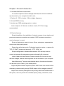
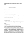
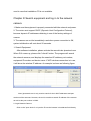
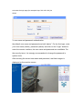
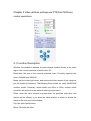
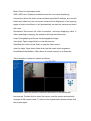
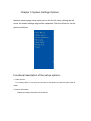
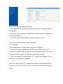
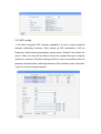
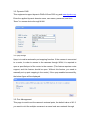
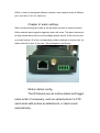
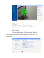
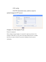
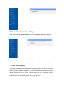
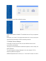
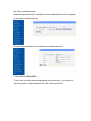
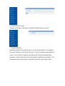
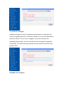
IP Camera Instruction Manual
WIFI Model No: IP-302-B
Chapter 1
…………… Product Introduction
Chapter 2
………………Product Installation
Chapter 3
Chapter
……………… Search equipment
4…………………
Video
attribute
settings
(Pan/Tilt/Zoom) control operations
Chapter 5
Chapter 6
Chapter 7
……………
System Settings options
……………… Network settings
………………
Chapter 8 ………………
System Tools
Logout
and
PTZ
Chapter 1 Product Introduction
1.1 Hardware/Software requirements:
To use the computer-camera through networks, the minimum hardware
requirements of your computer should be met,
1. Pentium III
CPU or better, 1GHz or higher frequency;
2. At least 256M memory;
3. windows xp, 2000 operating system or above
Internet explorer 4.0 browser or above version, IE 6.0 is strongly
recommended.
1.2 Product features:
Simple installation: the installation of network cameras is very simple, only
power and networks connection are needed. if WIFI wireless connection is
used, only power is a must.
Scope of applications: apply to home, offices, enterprises, supermarkets,
schools and other public places.
Supporting multiple protocols: Embedded operation system supports the
TCP / IP, SMTP (simple mail protocol), HTTP, UPNP, etc.
Simple configuration: Standard Web browser GUI can help users to
control and manage the networking cameras through LAN or Internet.
Video Views and Video Record: Provide concise GUI for user to view
real-time images, and the video segments can be recorded on your computer.
Alarm Monitoring: Through external alarm device, the alarm information
can be sent to your e-box or your mobile phone.
Support dynamic DDNS: Support Dynamic DNS. Users can access his/her
networking cameras easily through DDNS despite of the changed camera IP.
Simple User Authority Management: By setting USER and PASSWORD of
the system, user can protect the individual privacy easily, meanwhile, users
can be authorized to different permission levels to operate the network
camera.
Chapter 2 installation
2.1 Hardware installation
1. Connect the network:
Connect the networking camera to the router or switch.
2. Connect the power
Connect the networking camera with power.
Cautions: Please use the original power adaptor along with the camera;
otherwise, it may cause hardware damage.
3. Check the network indicator light
when power on, the camera starts working. Normally the green indicator
of the network cameras is on continuously and yellow light flashes.
2.2 Software Installation
Software installation is very simple, you only need to run ocx.exe and
installation can be finished automatically. There are two ways to install
software.
I: CD-ROM installation
1. Please put the attached CD into the CD-ROM driver in your PC.
2. Double-click ocx.exe and installation can be finished automatically.
Second: Download OCX.exe from the networking camera and install the same
1. When the software is not installed in your PC, meanwhile, the camera is
connected to the network, you will be prompted to download and install the
control software. You can download the same to any folder you want. After
downloading is completed, double-click OCX.exe and automatic installation
will be implemented. Downloading OCX.exe from the network camera is widely
used in case that installation CD is not available.
Chapter III Search equipment and log in to the network
camera
1: Make sure the equipment is properly connected with the network and power.
2: The router must support DHCP (Dynamic Host Configuration Protocol),
because dynamic IP addresses obtaining is one of the factory settings of
camera.
3: The camera can not be immediately used when power connection is OK,
system initialization will cost about 20 seconds.
1: Search Equipment
After software installation, please activate the search tools ipcamtools.exe.
When GUI comes up, please click "refresh" button. The program will search
the network cameras, and displays the searched IP address, port number,
equipment ID number and device name. If WIFI wireless connection is in use,
it will show the wireless IP address. An example is shown as following figure.
Note: (ipcamtools.exe is only used to search for the LAN IP addresses and port
numbers of the cameras. However, the tool is not able to search IP address of the camera
as well as the port number in WAN.
2: Login Network Camera
Click on the "open device" or input the IP into the browser in its address field directly
to access the login page (for example: http://192.168.1.92). As
shown
3: user name and password authentication
the default user name and password are both “admin”. For the first login, enter
your user name (admin), password (admin) and click on the "Login" button to
enter the monitor interface, the user name and password are modifiable. For
the security issue, it is strongly recommended to change the password in
system tools.
After entering the correct user name and password, real-time images is
displayed on the monitor screen.
Chapter 3 Video attribute settings and PTZ(Pan/Tilt/Zoom)
control operations
4.1 Function Description:
Window: the window is defined as video window number shown in the video
region ,the current maximum of which were 36.
Resolution: the size of the currently selected video. Currently supports two
sizes: 640x480 and 320x240.
Mode: set the video light mode, and remove the jitter impact of the image as
per the electricity frequency. The following three modes are used: 50HZ/60HZ
/outdoor model. Generally, indoor mode use 50Hz or 60Hz, outdoor mode
should be set as per the real camera working environment.
Effect: when the video window is greater than the specified video size, two
options will be offered, try to show the video window in center or stretch the
image to the real size of the window.
Flip: the video upside down.
Mirror: Reverse the video.
Mute: Check to close/open audio.
OSD, OSD color: Display the date/time and the color when displaying.
Connection: When the video camera window specifies IP address, click on this
button and video from the connected camera will be displayed. In the opening
pages of video surveillance, it will automatically connect the camera and video
will come.
Disconnect: Disconnect the video connection, and stop displaying video. If
video recording is ongoing, the operation will stop simultaneously.
snap: Photographing and save the photographed image.
View snap: Open image folder to view the pictures.
Start/Stop the video record: Start or stop the video record.
view the video: Open video folder and view the saved video segments.
ClearAlram/ClearAllAlarm: Stop alarm of current channel or all channels.
Video operation interface is shown as follows:
Description: when the window is selected, the border of the window will
become red. Double-click to select the screen, and the screen automatically
changes to full-screen mode. To return to its original state, please double-click
the screen again.
Chapter V System Settings Options
Network camera page setup options are in the far left, when clicking the left
arrow, the hidden settings page will be expanded. Click the left arrow, set the
options as follows
Functional description of the set-up options:
1: video monitor
For viewing video, in any case you can click on this button to enter the video mode to
watch.
2: Device Information
Display the status information of the device.
Note: The device name can be changed:
1, User can customize the name of the device in order to distinguish different
equipments.
2, When the video surveillance equipment connected, the page will show the
device and the name.
3, The search tool can also display the searched device names.
3: Net config: set up network-related parameters.
3.1: IP settings
The set supports two modes of distribution network address:
1, to obtain IP address automatically (DHCP): Select DHCP, device will
automatically obtain the IP, which is not fixed (this feature requires the router
to support DHCP protocol, and this feature should be activated).
2, using the specified IP address (static IP): To specify the equipment IP, it is
required to manually fill in IP address.
Select the required mode, fill in relevant information by the Depositary and
click on the “Save” button. This function of equipment need to restart to take
effect.
3.2: WiFi config
1, the device supports WiFi wireless capabilities. If user’s camera supports
wireless networking functions. After setting up WiFi parameters, such as
Password, Authentication parameters, please select "Enable" and restart the
device. Then, the user will be able to access the network through a wireless
network of cameras. (Wireless settings must be in strict accordance with the
password authentication method parameters of the wireless router, otherwise,
it can not connect wireless network
3.3: Dynamic DNS
This equipment support dynamic DNS of Www.3322.org and www.dyndns.org.
Enter the applied dynamic domain name, user name, password, and click
“Save” to access device through WAN.
3.4: upnp settings
Upnp is to realize automatic port mapping function. If the camera is connected
to a router, In order to access to the cameras through WAN, it is required to
open a specified port of the router to the camera. (This feature requires router
support, and this feature should be open. Without this feature, you need to
manually set up port mapping in the router). If the upnp enabled successfully,
the below figure will be displayed.
3.5: Port Management
This page is used to set the camera's external ports, the default value of 80. If
you want to visit the multiple cameras in a same local area network through
WAN, in order to distinguish different cameras, each camera needs a different
port, such as 81, 82, etc. and so on.
Chapter VI alarm settings
Alarm camera settings are used to set the alarm function of network camera.
When external alarm signal is triggered, alarm will come. The alarm device can
be high sound alarm device or sound &light alarms device. If the user has set
up e-mail function, fill in the corresponding mailbox address to receive mail. An
alarm mail will be sent to the user. Wiring diagram is as follows.
Motion detect config
The IPCamera can do motion detect and trigger
some action if necessary, such as upload picture to FTP,
send email with picture as attachment, or start record
automatically.
IO Alarm
Enable or disable IO alarm at this page.
SMTP config
Provide email sender information here, which is
need for send email when motion detects or other alarm is
occurring.
FTP config
Fill FTP information here, which is need to
upload images to FTP server.
Chapter VII of the System Tools
Restart the equipment
When settings changes happen, it is required to restart your device to the
changes to take effect, you can click on the page "Reboot Device" to enable
the device to restart. Another 20 seconds is needed to finish the device
initialization.
7.2 to restore the factory settings
Click "reset configt" will enable the device to restore all settings to factory
default, the default user name and password are both “admin”.
Note: The factory default settings using DHCP to obtain IP address. After restoring the
factory settings, device IP address may be different from the one before restoration.
Please use the search tool to search for equipment. And obtain the corresponding IP.
7.3 User Management
In this page, user permissions management is applied. According to different users name,
different operating authority setting can be configured. Administrator has the privilege to
operate all functions of the camera. Ordinary users can only watch the video and
implement PTZ operations. And visitors can only see the video.
The following are the Edit and Modify interface:
Users can be enabled or disabled. The disabled users can’t log on equipment
page.
Description: user "admin" is the super-administrator user, who can set up and
operate all the functionalities of all the networking cameras.
7.4 Multiple Devices Manager
In this page, not only the main video, but also additional device can be
connected be automatically.
This page is for the maintenance of additional equipment, create, modify, and
delete equipment.
The main equipment is always displayed on the video channel 1 (CH 1),
followed by additional equipment.
Additional equipment can be "move up" or " move down" to adjust- its order in
the video surveillance page.
Additional equipment can be disabled, and the disabled device will not appear
in the video surveillance page
The next figure describe how to add/edit the additional device.
7.5 Local configuration
To set video recording and photographing saving directory, it is required to
input save path in "captured photo file" and "video record file".
7.6 Download Ocx control
Clicking on the link in this page is available for download ocx control.
7.7 Update Software
Updating software is to enable users to use the latest software. The upgrade
file name is app.bin, Click button "Browse" to find out the path where app.bin is
stored. You can click to upgrade, the system will show the upgrading files
progress, success information will be prompted if upgrading successfully. The
new networking camera must be restarted to take the new program effect.
7.8 update the webpages
Updating web page is mainly to upgrade the appearance of web pages, file
name for upgrading www.bin, Click button "Browse" to find out the path where
www.bin is stored. You can click to upgrade, the system will show the
upgrading files progress, success information will be prompted if upgrading
successfully. The new networking camera must be restarted to take the new
program effect.
Chapter VIII Logout
Logging out from the current registry, it will return to the login page.
Login
must be accomplished again if the user wants to operate the equipment again.