1
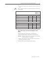
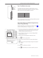
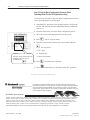
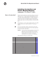
Quick Start for Experienced Users (Catalog Nos. 1771-QI and 1771-QDC) What’s in This Quick Start? This document describes how to install and configure co-injection modules (cat. no. 1771-QI) and plastic molding modules (cat. no. 1771-QDC). Plastic molding modules (1771-QDC) can be used to control inject, clamp, and eject phases of an injection molding machine. You can also use the QDC modules to control the clamp and eject phases when you use the QI modules to control the inject phase. In this document, we refer to plastic molding modules (1771-QDC) as QDC modules, and co-injection modules (1771-QI) as QI modules. You can use QI and QDC modules with applications other than Pro-Set 700 software. In this document, we note where procedures are specific to Pro-Set 700 software. Important: If you are using co-injection modules in a Pro-Set 700 application, you must install Pro-Set 700 software Release 2.02 or above and Pro-Set 700 Co-injection software Release 2.02 or above. Contact your Allen-Bradley sales representative for information. This Quick Start will help you to do these tasks: step task page 1 choose the correct power supply 3 2 determine the I/O chassis addressing mode 3 3 determine the modules’ positions in the chassis 3 4 key chassis slots for the modules 4 5 determine and record I/O ranges 4 6 make jumper connections on the modules’ circuit boards 5 7 install the modules into the chassis 7 8 ground and shield I/O devices 7 9 make a proper ground connection 8 10 familiarize yourself with the PLC processor power distribution circuit 8 11 wire the modules 8 12 power up the modules 8 13 read module indicator lights 9 14 enter I/O ranges on the Module Configuration screen (Pro-Set 700 only) 9 15 use the Rack Configuration screen to select operating mode (Pro-Set 700 only) 10 Publication 6500-10.1 – March 1996 2 Installing Co-injection and Plastic Molding Modules Related Publications This document provides an abbreviated procedure for installing the modules. Refer to the appropriate manual for complete procedures. To order additional manuals, contact your local Allen-Bradley sales representative. You can order the Plastic Molding Module Documentation Set (6500-QDCDOC), or the individual manuals, as listed below. To do this task: Use this manual: title publication no. Install and configure co-injection (QI) modules Pro-Set 700 Co-injection Software User Manual 6500-6.5.19 Install plastic molding (QDC) modules Plastic Molding Module Inject Mode Manual1 1771-6.5.85 Plastic Molding Module Inject and Clamp Mode Manual1 1771-6.5.86 Plastic Molding Module Clamp and Eject Mode Manual1 1771-6.5.87 Plastic Molding Module Inject, Clamp, and Eject Mode Manual1 Plastic Molding Module Application Guide1 1771-6.5.93 Determine plastic molding (QDC) module operating modes Use the QDC module with your machine’s hydraulic system Configure QDC modules 1771-4.10 Pro-Set 700 Software User Manual 6500-6.5.18 Find reference information, such as command and status bits, for the QI module Pro-Set 700 Co-injection Software User Manual 6500-6.5.19 Find reference information, such as command and status bits, for the QDC module Plastic Molding Module Reference Manual1 1771-6.5.88 Pro-Set 700 Software Reference Manual 6500-6.4.3 1 Contained in the Plastic Molding Module Documentation Set (6500-QDCDOC) What if I Want Other Pro-Set 700 Publications? You can order the Pro-Set 700 Documentation Set (cat. no. 6500-PS7DOC) for more information. Or, if you prefer, you can order the publications in the documentation set individually. Contact your Allen-Bradley sales representative or distributor to order. To order the Pro-Set 700 publications individually, use these publication numbers. Publication 6500-10.1 – March 1996 title publication no. Installing Pro-Set 700 Software 6500-5.3 Pro-Set 700 Software User Manual 6500-6.5.18 Pro-Set 700 Software Reference Manual 6500-6.4.3 Pro-Set 700 Operator Interface Installation Manual 6500-6.2.1 Jobsetting Guide for Pro-Set 700 Systems 6500-6.9.3 ControlView Runtime Reference Manual 6195-6.5.4 ControlView Statistical Process Control User Manual 6195-6.5.20 Installing Co-injection and Plastic Molding Modules Installing the Modules 3 Follow the procedures in this section to install the QI and QDC modules. ! ATTENTION: Remove power from the I/O chassis backplane and wiring arm before removing or installing modules. Failure to remove power could cause injury or equipment damage due to unexpected operation. Step 1. Choose the Correct Power Supply The modules are powered through the chassis backplane with a power supply. To select the correct power supply for the system, ensure that the total current load for all modules does not exceed the power supply’s maximum load specification. To calculate the total current load: 1. Add the modules’ current loads to the loads of all other modules in the chassis. Important: The QI and QDC modules are rated at 1.2A. Check specifications for all other modules in the I/O chassis. 2. Compare your total with the power supply’s maximum load rating. 3. If the total voltage exceeds the power supply’s maximum load rating, select a larger power supply. See your Allen-Bradley representative for more information. Important: We recommend a standalone power supply, such as catalog number 1771-P1. This power supply is mounted beside the I/O chassis and provides an output of up to 16A. Step 2: Determine I/O Chassis Addressing Mode Each module has 4 inputs and 4 outputs and is compatible with single-slot addressing. Step 3: Determine the Modules’ Positions in the Chassis Refer to the appropriate manual for the modules’ positions in the chassis. Publication 6500-10.1 – March 1996 4 Installing Co-injection and Plastic Molding Modules Step 4: Key the I/O Chassis for the Co-injection Modules Use the plastic keying clips shipped with each I/O chassis to key the appropriate I/O slots to accept only the QI or QDC modules. The modules are slotted in two places on the rear edge of the circuit board. The keying clips you install must correspond to these slots to allow the module to be inserted only in the designated slot. I/O chassis Install keying clips between S 20 and 22 S 26 and 28 Upper backplane connector 11022-I Step 5: Determine and Record I/O Ranges You must determine module I/O ranges before you can make jumper selections. To determine I/O ranges, follow these steps. We provide a blank worksheet on the next page that you can complete for each module. 1. For co-injection applications, determine whether the module will control injection unit A or B. 2. Determine the inputs you want the modules to monitor. Record your input selections on the worksheet. 3. For co-injection applications, select screw A or B for inputs 1 through 4. Your screw selections must match your module selections. 4. Refer to the specifications that accompanied your sensors to determine the operating range. 5. Determine the outputs you want the modules to control. Record your output selections on the worksheet. 6. Determine the sensors and valves that the injection molding machine will use to monitor and control system operation. Publication 6500-10.1 – March 1996 Installing Co-injection and Plastic Molding Modules 5 7. Circle the I/O ranges on the worksheet for each sensor and valve used. ✍ Here is a blank worksheet you can photocopy and use to record your own I/O ranges. Module Operating Modes: (for co-injection applications, select module A or B Module A __n Module B__n Inputs Signal Ranges Input 1 0 to 10V dc 1 to 5V dc 4 to 20 mA Input 2 0 to 10V dc 1 to 5V dc 4 to 20 mA Input 3 0 to 10V dc 1 to 5V dc 4 to 20 mA Input 4 0 to 10V dc 1 to 5V dc 4 to 20 mA Outputs Signal Ranges Output 1 -10 to 10V dc 0 to 10V dc 4 to 20 mA Output 2 -10 to 10V dc 0 to 10V dc 4 to 20 mA Output 3 -10 to 10V dc 0 to 10V dc 4 to 20 mA Output 4 -10 to 10V dc 0 to 10V dc 4 to 20 mA Step 6: Make Jumper Connections on the Modules’ Circuit Boards After determining I/O operating ranges, you make jumper connections on the modules’ circuit boards to select the ranges. Important: Handle the circuit board by the edges to avoid touching conductive surfaces or components. 1. Remove the module cover plate (on the label side) by removing the four screws holding it in place. 2. Remove the circuit board from the module housing. Publication 6500-10.1 – March 1996 6 Installing Co-injection and Plastic Molding Modules Top 3. Orient the circuit board as shown in the figure. E1 4. Locate the jumper plugs as shown in the figure. 5. Use a pair of small needle-nose pliers to pick up and place the jumper plugs. Refer to the table below for the correct settings. E5 Left Right E6 E7 6. Re-assemble the module. E8 E9 E15 E16 E12 E11 E10 E14 E13 E17 Bottom jumper function setting comments E1 run/calibrate calibrate = right run = left (default) E5 I/O density standard = top (default) do not use bottom position E6 E7 E8 E9 input 1 input 2 input 3 input 4 voltage = right (default) current = left E10 E14 E13 E17 output 1 (Valve 1) output 2 (Valve 2) output 3 (Valve 3) output 4 (Valve 4) current = top voltage = bottom (default) If you select current output with E10, E14, E13, and/or E17, you must select the 4 to 20 mA position with E11, E12, E15, and/or E16. E11 E12 E15 E16 output 1 (Valve 1) output 2 (Valve 2) output 3 (Valve 3) output 4 (Valve 4) -10 to +10V dc = top 0 to +10V dc or 4 to 20 mA = bottom (default) If you select current output with E10, E14, E13, and/or E17, you must select the 4 to 20 mA position with E11, E12, E15, and/or E16. For bi-directional valve operation, if an output is unconnected, set the jumper (E11, E12, E15, and/or E16) for that output to 0 to 10V dc (bottom position). Important: Setting the jumpers for –10 to +10V dc and later configuring the output as unconnected causes the modules to output –10V dc when stopped, or when the system resets. All outputs are forced to 0%, since 0% = –10V dc. Publication 6500-10.1 – March 1996 Installing Co-injection and Plastic Molding Modules 7 Step 7: Install the Modules into the Chassis Follow these steps to install the modules. ! ATTENTION: Remove power from the chassis backplane and disconnect the cable from the module before installing or removing a module. Failure to remove power may cause injury, damage, or loss of performance. 1. Turn off power to the I/O chassis. 2. Place the module in the plastic tracks (on the top and bottom of the slot) that guide the module into position. 3. Slide the module into the chassis. Apply firm, even pressure on the module to seat it against the backplane connector. ! ATTENTION: Do not force the module into the backplane connector. Doing so may damage the module or the connector. 4. Snap the chassis latch over the top of the module to secure it in the chassis. 5. Attach the wiring arm (1771-WF) to the rack. Step 8: Ground and Shield I/O Devices Analog inputs and outputs are sensitive to electrical noise. Be sure to properly shield all devices. Refer to the appropriate manual for more information. Publication 6500-10.1 – March 1996 8 Installing Co-injection and Plastic Molding Modules Step 9: Make a Proper Ground Connection ! ATTENTION: Electrostatic discharge can damage semiconductor devices inside the module if you do not handle the module properly. Follow the guidelines below. 1. Wear a wrist-strap grounding device. Attach this end to a good earth ground 2. Attach the free end to a good earth ground. Important: Do not touch the module backplane connector or pins. Store the module in an anti-static bag when you are not using it or during shipment. 3. Touch a grounded object (such as a metal enclosure) to rid yourself of electrostatic discharge before you handle the module. Step 10: Familiarize Yourself with the PLC Processor Power Distribution Circuit Refer to the appropriate manual for a typical grounded power distribution circuit for PLC processors. For ungrounded systems, or for more information on wiring and grounding, refer to Allen-Bradley Programmable Controller Wiring and Grounding Guidelines, publication 1770-4.1. Step 11: Wire the Modules Use the wiring arms (provided with the modules) to wire the modules. The wiring arm lets you install or remove the modules from the chassis without rewiring. Wiring arm terminals are numbered in descending order from the top down, starting with terminal 18. Refer to the appropriate manual for a wiring diagram. Important: Use shielded cable between the modules. Step 12: Power up the Modules 1. Make all power connections from the I/O chassis to the in-plant power source. 2. Apply power to the chassis power supply. Publication 6500-10.1 – March 1996 Installing Co-injection and Plastic Molding Modules 9 Step 13: Read Module Indicator Lights ACTIVE FAULT COMM The module front panel contains three indicators that you use to troubleshoot the module during integration or operation. Check the lights to ensure that no fault conditions are present. LED color ACTIVE green FAULT red COMM yellow Refer to the appropriate manual for the operating conditions reported by the module, and how to correct them. Step 14: Enter I/O Ranges on the Module Configuration Screen (Pro-Set 700 Applications Only) Enter the information you recorded on the worksheet on page 5 on the Plastic Molding Module(s) Configuration screen. 1. If you have not already done so, attach the PLC processor to the operator interface. Refer to the Pro-Set 700 Operator Interface Installation Manual, publication 6500-6.2.1. 0 to 10V dc –10 to 0V dc 2. From the Hardware Setup menu, select the Configure Plastic Molding Module(s) screen. 3. Move the cursor to the appropriate field on the screen. 4. Press Make your selection from the pop-up list that appears when you cursor to the field and press . . You see a pop-up menu. 5. Place the cursor on the selection you want to make and press . You can select input and output voltages for the QI and QDC modules. 6. Press to confirm your selections. 7. Press to download your selections to the PLC processor. Publication 6500-10.1 – March 1996 10 Installing Co-injection and Plastic Molding Modules Step 15: Use the Rack Configuration Screen to Select Operating Mode (Pro-Set 700 Applications Only) Use the Pro-Set 700 and Co-injection Rack Configuration screens to select operating modes for each module. 1. Attach the PLC processor to the operator interface. Refer to the Pro-Set 700 Operator Interface Installation Manual, publication 6500-6.2.1. 2. From the Setup menu, select the Rack Configuration screen. 3. Move the cursor to the appropriate field on the screen. 4. Press . You see a pop-up menu. 5. Place the cursor on the selection you want to make and press Not Used Inject . You can select: • PLC type • machine type Make your selection from the pop-up list that appears when you cursor to the field and press . • mode of operation 6. Press to confirm your selections. 7. Press to download your selections to the PLC processor. PLC and Pro-Set 700 are trademarks of Allen-Bradley Company, Inc. Allen-Bradley, a Rockwell Automation Business, has been helping its customers improve productivity and quality for more than 90 years. We design, manufacture and support a broad range of automation products worldwide. They include logic processors, power and motion control devices, operator interfaces, sensors and a variety of software. Rockwell is one of the world’s leading technology companies. Worldwide representation. Argentina • Australia • Austria • Bahrain • Belgium • Brazil • Bulgaria • Canada • Chile • China, PRC • Colombia • Costa Rica • Croatia • Cyprus • Czech Republic • Denmark • Ecuador • Egypt • El Salvador • Finland • France • Germany • Greece • Guatemala • Honduras • Hong Kong • Hungary • Iceland • India • Indonesia • Ireland • Israel • Italy • Jamaica • Japan • Jordan • Korea • Kuwait • Lebanon • Malaysia • Mexico • Netherlands • New Zealand • Norway • Pakistan • Peru • Philippines • Poland • Portugal • Puerto Rico • Qatar • Romania • Russia–CIS • Saudi Arabia • Singapore • Slovakia • Slovenia • South Africa, Republic • Spain • Sweden • Switzerland • Taiwan • Thailand • Turkey • United Arab Emirates • United Kingdom • United States • Uruguay • Venezuela • Yugoslavia Allen-Bradley Headquarters, 1201 South Second Street, Milwaukee, WI 53204 USA, Tel: (1) 414 382-2000 Fax: (1) 414 382-4444 Publication 6500-10.1 – March 1996 Publication 6500-10.1 – March 1996 PN 955125-43 Copyright 1996 Allen-Bradley Company, Inc. Printed in USA