1
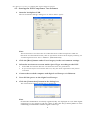
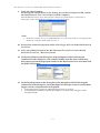
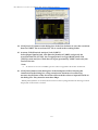
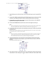
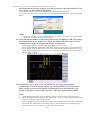
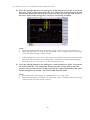
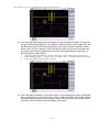
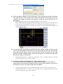
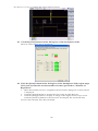
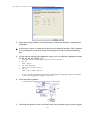
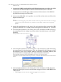
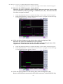
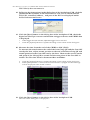
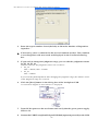
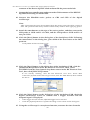
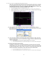
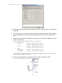
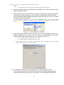
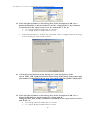
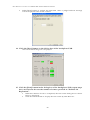
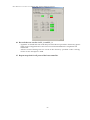
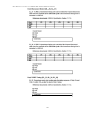
Host HS Test Procedure for YOKOGAWA DL9240/DL9240L/DL6154 the Downstream Device Control drop down menu in the HS Electrical Test Tool then click the [EXECUTE] button. If not already running, start the HS Electrical Test Tool. Select Host Controller/System under Select Type of Test, click the TEST button, then confirm the above. Note: If the host under test is an embedded host, set its test mode to an appropriate mode by using the dedicated tool for it. 14. Click the [Next] button in the dialog box of the busXplorer-USB. Following the instructions in the dialog box, check the digital oscilloscope screen to confirm that a trigger activates and packet is displayed. • • If the trigger does not activate, adjust the trigger level as needed. Then, select SINGLE STEP GET DEV DESC again from the Device Command drop down menu in the HS Electrical Test Tool, and click the [EXECUTE] button again. Click the [Update] button to update the image of waveform in the dialog box of the busXplorer-USB. 15. Confirm the Sync field of the 1st packet (EL_21). Using the digital oscilloscope’s zoom function, adjust the zoom position on the 1st packet. Then set the cursors of the digital oscilloscope on the start and the end points of the Sync field of the 1st packet. The Sync field must be 32bits. Note: Click the [Update] button to update the image of waveform in the dialog box. When [Next] button is clicked, the measured value is judged and Fail message will be displayed if the result is failed. When setting the cursor on the Sync field, note that the Sync field starts from the Hi-Speed idle transitions to a falling edge. Count both rising and falling edges until the first two consecutive 1’s and include the first 1. 22