1
CNC User’s Manual
P/N 627 785-22 - Canned Cycles and Subprograms
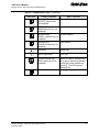
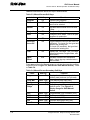
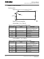
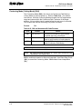
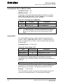
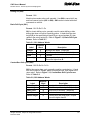
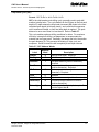
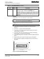
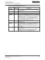
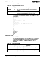
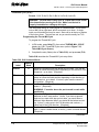
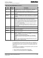
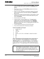
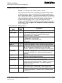
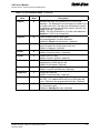
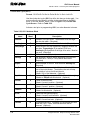
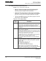
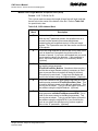
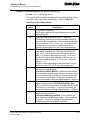
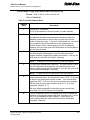
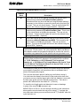
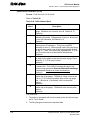
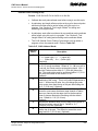
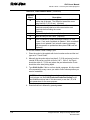
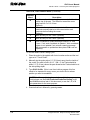
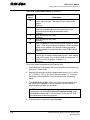
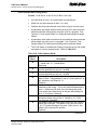
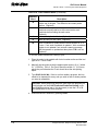
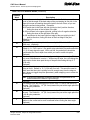
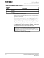
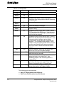
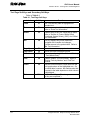
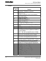
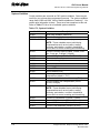
Table 5-44, G154 Address Word (Continued)
Address
Word
Description
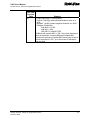
M
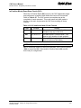
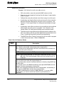
This is the override for the medium feedrate that was set in the
machine setup parameter ZFirstPickFeedRate_Medium.
Sometimes there may be a tool that has a large diameter making it
necessary to slow it down to prevent the touch probe from being hit
too hard. This can only be set slower. Trying to set this higher will
result in the software using the original feedrate. (Optional)
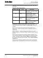
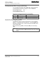
S
This is the override for the slow feedrate that was set in the
machine setup parameter ZFirstPickFeedRate_Slow. This is used
for the same reason as the M cycle parameter. This can only be
set slower. Trying to set this higher will result in the software using
the original feedrate. (Optional)
R
This is the override for the RPM that was set in the machine setup
parameter calibAndToolMeasurementRPM. This is used for the
same reason as the M cycle parameter. This can only be set
slower. Trying to set this higher will result in the software using the
original RPM. (Optional)
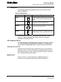
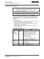
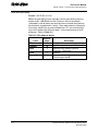
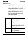
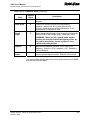
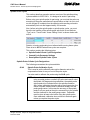
WARNING: Large tools can result in probe damage if the touch feedrate
is set too fast. For this reason, the cycle parameters: M, S, and R have
been added to enable the programmer/operator to override the values in
the machine setup parameters for the specific tool being checked or set.
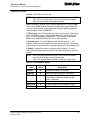
WARNING: Running this cycle without first initially setting the length and
diameter offset could result in damage to the probe and/or the machine
tool. G150 Calibration and G151 Automatic Tool Length and
Diameter set, or G152 Manual Tool Length Measure for Special Tools
and G153 Manual Tool Diameter Measure for Special Tools, must be
run first before using the G154 cycle.
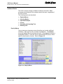
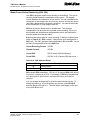
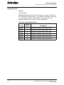
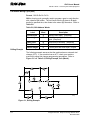
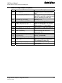
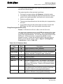
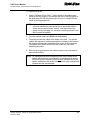
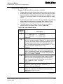
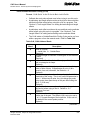
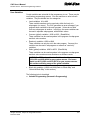
The G154 cycle loads the tool, checks, and updates length and diameter
wear registers if specified, until a maximum value is exceeded, then it
alarms out stopping the program.
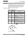
This cycle can be used in place of calling up a tool before running it.
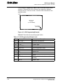
You must know the distance from the top of the probe stylus down that
you have to move so that the largest part of the tool diameter is even with
the side of the probe stylus for diameter measurement. That value is
placed in E if different then the default 0.1” (2.54 mm).
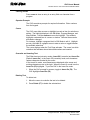
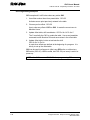
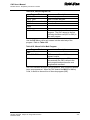
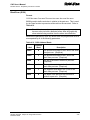
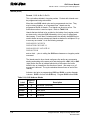
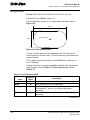
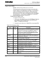
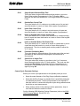
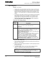
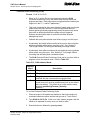
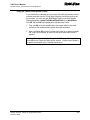
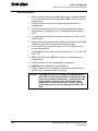
To check the tool length and/or tool diameter for wear or breakage:
In place of the usual Tn M6 command, use:
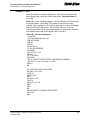
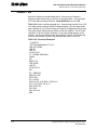
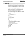
G154 Tn Dn Kn Jn En Un” at a tool change according to the instructions
above and the control checks the tool prior to using it. To activate the
new offset wear values you must call that tool with “T(Tool#) M6” after this
cycle has been run.
5-76
All rights reserved. Subject to change without notice.
November 2009