1
FACTORY AUTOMATION
MANUAL
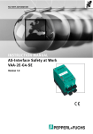
VAA-2E-G4-SE
Original Instructions
Version 1.1
VAA-2E-G4-SE
With regard to the supply of products, the current issue of the following document is applicable: The General Terms of Delivery for Products and Services of the Electrical Industry, published by the Central Association of the Electrical Industry (Zentralverband
Elektrotechnik und Elektroindustrie (ZVEI) e.V.) in its most recent version as well as the
supplementary clause: "Expanded reservation of proprietorship"
VAA-2E-G4-SE
1
Declaration of Conformity.......................................................... 5
2
Used Symbols ............................................................................. 6
3
Safety ........................................................................................... 7
3.1
Intended use......................................................................................... 7
3.1.1 Safety Monitor requirements .............................................................. 7
3.1.2 Wiring requirements........................................................................... 7
3.1.3 Light grids and light curtains .............................................................. 7
4
3.2
General safety instructions ................................................................. 8
3.3
MTTFd, PFD and PFH........................................................................... 8
Product Description ................................................................... 9
4.1
Operating Principles of the input channels....................................... 9
4.2
Connections and LED indications.................................................... 10
4.3
Interface properties ........................................................................... 12
4.3.1 AS-Interface, auxiliary power ........................................................... 12
4.3.2 Transmitter and receiver................................................................... 12
4.3.3 Shielding.......................................................................................... 12
4.4
Inputs .................................................................................................. 12
4.4.1 General ............................................................................................ 12
4.4.2 Safety classification ......................................................................... 13
4.4.3 Channel short circuit monitoring ...................................................... 13
5
Commissioning......................................................................... 14
5.1
Configuration requirements for the safety monitor ........................ 14
5.2
Installation .......................................................................................... 14
5.3
Module addressing ............................................................................ 15
5.4
Functionality Test ............................................................................... 15
6
AS-Interface safety module ..................................................... 16
7
Certificates ................................................................................ 17
3
VAA-2E-G4-SE
A
4
Summary of the requirements for categories
to EN 954-1/ISO 13849-1.......................................................... 18
VAA-2E-G4-SE
Declaration of Conformity
1
Declaration of Conformity
All products were developed and manufactured under observance of the applicable European
standards and guidelines.
Note!
A Declaration of Conformity can be requested from the manufacturer.
The product manufacturer, Pepperl+Fuchs GmbH, 68307 Mannheim, has a certified quality
assurance system that conforms to ISO 9001.
182362 2014-11
ISO9001
5
VAA-2E-G4-SE
Used Symbols
2
Used Symbols
Safety-relevant Symbols
Danger!
This symbol indicates an imminent danger.
Non-observance will result in personal injury or death.
Warning!
This symbol indicates a possible fault or danger.
Non-observance may cause personal injury or serious property damage.
Caution!
This symbol indicates a possible fault.
Non-observance could interrupt devices and any connected systems and plants, or result in
their complete failure.
Informative Symbols
Note!
This symbol brings important information to your attention.
Action
182362 2014-11
This symbol indicates a paragraph with instructions.
6
VAA-2E-G4-SE
Safety
3
Safety
3.1
Intended use
The AS-Interface safety module permits the connection of one two-channel ESPE to safeguard
danger zones or areas in a system utilizing AS-Interface 'Safety at Work'. It must be used as
intended with a properly configured AS-Interface safety monitor and a suitable ESPE (safety
light curtain or light grid with electronic OSSDs.). This allows the implementation of safety
applications up to the following categories:
■
PL e / Category 4 according to EN ISO 13849-1
■
SIL 3 according to EN/IEC 61508 / EN/IEC 62061
■
Type 4 based on EN/IEC 61496-1
The safety requirements for the application are determined by either a risk analysis (i. e. based
on EN 1050) or derived from a C-standard.
In addition to the instructions included in this user manual, all applicable safety requirements,
standards and regulations as well as operating instructions for the connected peripheral
devices must be considered.
Danger!
Use the module in accordance with its intended use.
Otherwise the protection of operating personnel and equipment is not ensured.
3.1.1
Safety Monitor requirements
The module shall only be used as a safty slave in an AS-Interface network and must be
connected to a suitable AS-Interface safety monitor. All instructions in the user documentation
must be followed. The AS-Interface monitor must fulfill the requirements of the system
specifications version 2.01 dated 12.05.2000 ("Spezifikation der sicheren AS-InterfaceUebertragung") or higher.
In order to evaluate a safety related function based on a safety standard all components of the
function have to be evaluated according to the same safety standard.
The correct execution of a desired safety function also depends on the proper connection and
configuration of the AS-Interface safety monitor. This also applies to the desired reaction when
safety codes are corrupted or the unit exhibits a hardware fault (refer to the documentation of
the AS-Interface safety monitor). The safety function (including all attached safety devices)
must be tested before the first startup. The minimal requirement for the safety classification of
the safety monitor needs to match the safety classification required by the application.
3.1.2
Wiring requirements
The demands of the EN/IEC 60204-1 (or similar standard) must always be considered. The
requirements for the external wiring and the selection of connected safety devices depend on
the desired functionality as well as on the required safety classifications
Wires have to be safeguarded against simultaneous short circuit connections of the inputs SE1
and SE2 to the positive supply.
3.1.3
Light grids and light curtains
182362 2014-11
Safety systems must use ESPEs that satisfy EN/IEC 61496-1 and offer short-circuit protection
between channels. Type SLC and SLPCM light curtains (devices with an integrated controller)
are recommended. For application details refer to the user manuals of the connected safety
devices.
The time limits for positive test pulses given in the data sheets must be observed.
7
VAA-2E-G4-SE
Safety
3.2
General safety instructions
Danger!
Any operation differing from what is described in this user manual may compromise the safety
and functionality of the connected system.
The module should only be used by trained operators according to these instructions.
Installation and maintenance of the module under power shall only be performed by trained
electricians.
If malfunction of the module cannot be corrected it must be taken out of operation and
safeguarded against being inadvertently put back into operation.
Repair work shall only be performed by the manufacturer.
Alterations of or on the device are prohibited and void any warranty claims.
The requirements for the installations of a housing in IP67 applications need to be checked
before operating the device.
Note!
Plant management has the responsibility to comply with the requirements of local regulations.
3.3
MTTFd, PFD and PFH
In order to calculate the PFD (probability of dangerous failure on demand) of a safety related
function it is crucial to consider the PFD values of all components used in this function.
At low demand rates the average PFD depends on the average environmental temperature:
PFD
TA = 40 °C
TA = 55 °C
2,5 . 10-5
4,7 . 10-5
At a high demand rate for the safety function the average probability of dangerous failure per
hour (PFH) of the safety function is:
PFH
TA = 40 °C
TA = 55 °C
1,54 . 10 -9 1/h
3 . 10-9 1/h
The mean time to dangerous failure MTTFd and the diagnostic coverage DC is:
TA = 40 °C
TA = 55 °C
MTTFd
1500 years
740 years
DC
99,4 %
99,3 %
These values apply to equipment use for up to 10 years.
182362 2014-11
PFD, PFH and/or MTTFd values of other components, especially the safety monitor, are found
in their respective documentations.
8
VAA-2E-G4-SE
Product Description
4
Product Description
4.1
Operating Principles of the input channels
The safety module generates a code sequence of 4-bit code words. A safety monitor evaluates
the correctness of the code sequence. As soon as the connected peripheral device reports an
undisturbed operation of the application to the module, the code sequence is transmitted
through the AS-Interface network.
If the safety monitor determines a code sequence as being incorrect, it starts the transition to a
safe system state based on its configuration. If the peripheral device signals the activation of
the safety function, the transmission of the code sequence is terminated.
The module has two inputs for two separate and independently operating input channels. Each
channel operates on two of the 4-bit code words.
Both channels are required when connecting a safety device. If the safe state is initiated 4-bit
code words with the value 0000 will be transmitted.
SE1 SE2
Pulse filter
AS-Interface Bus
AS-Interface
Chip
DI0
DI1
Diag
2 mA
5V
&
&
Code
Generator
DI2
DI3
Diag
2 mA
5V
&
&
Strobe
Figure 4.1
Code generation
The safety monitor goes into the safe state without reporting a malfunction, as soon as the
code word 0000 is received. If one bit of a 4-bit code word differs from the expected code word,
the safety monitor actuates the safe state for the equipment and indicates a fault.
182362 2014-11
The two input channels are independent. The safety monitor evaluates the synchronicity of two
input signals depending on its configuration.
9
VAA-2E-G4-SE
14
n.c.
n.c.
12
Shield
9
11
24V+
Transmitter
Supply
(0 V)
Shield
0V
Receiver
8
10
13
Shield OSSD1 OSSD2
Supply
(24 V DC)
Shield
7
Supply
(24 V DC)
6
2
Supply
(0 V)
1
Supply
(24 V DC)
Module
5
SE2
4
n.c.
3
SE1
Supply
(0 V)
Product Description
Shield
0V
24V+
Functional ground (FG)
Ground connection via cage-clamp terminal
Figure 4.2
4.2
example: a light curtain with 2 outputs uses both channels of the module
Connections and LED indications
Ue
AS-Interface +
6
7
AS-Interface -
5
3
Supply (0 V)
Supply (24 V DC)
SE2
SE1
PWR
13
12
10
4
2
AUXUAUX
Ik
>
AUX
AUX+
1
11
10
Supply (0 V)
Shield
Shield
Supply (0 V)
Supply (0 V)
Supply (24 V DC)
Shield
Terminal
Function
Description
1
Supply 24V
power supply 1
(receiver)
2
Supply 0V
power supply 1
(receiver)
3
SE1
input signal 1
4
Supply 0V
power supply 1
(receiver)
5
SE2
input signal 2
182362 2014-11
FAULT
VAA-2E-G4-SE
Product Description
Terminal
Function
Description
6
Supply 0V
power supply 2
(receiver)
7
Supply 24V
power supply 2
(receiver)
8
Supply 24V
power supply 3
(transmitter)
9
Supply 0V
power supply 3
(transmitter)
10
Shield
functional ground
for transmitter
11
Shield
functional ground
for the module
12
Shield
functional ground
for receiver
13
Supply 0V
power supply 1
(receiver)
14
n.c.
-
182362 2014-11
SE1
PWR
FAULT
SE2
AUX
SE1
AS-Interface (yellow flat cable) and auxiliary power U AUX (black flat cable) are connected using
an appropriate mounting base (sold separately).
SE2
Function
Description
FAULT
fault indication: LED red:
red: AS-Interface
communication error
and/or module address is 0
PWR
AS-Interface power on; LED
green
AUX
auxiliary power UAUX; LED
green
SE1
input channel 1 indicating run
mode; LED yellow
SE2
input channel 2 indicating run
mode; LED yellow
11
VAA-2E-G4-SE
Product Description
4.3
Interface properties
4.3.1
AS-Interface, auxiliary power
AS-Interface and auxiliary power UAUX are connected by using an appropriate mounting base
(sold separately).
The AS-Interface connection is reverse polarity protected and the maximum available current is
internally limited.
The auxiliary power connection is also protected against reverse polarity.
The module is protected against overloads on its ouputs by a self healing fuse.
4.3.2
Transmitter and receiver
Transmitter and receiver are connected by spring terminals. Every lead of the cable from the
safety device must be connected to a terminal on the connection block. This is necessary to
prevent the occurrence of internal short circuits.
The power supply terminals may be used arbitrarily.
The two supply power connections on the terminal block inside the module are at the same
potential and overload protected with respect to auxiliary power. When auxiliary power is
reversed the auxiliary power on the terminal block of the module is also reversed.
The inputs are designed to be power limiting and operate according to EN/IEC 61496-1 and EN
61131-2.
ESPE are permitted to generate test pulses on the module inputs. The width and frequency of
these test pulses are typically listed in the user manual or data sheet of the safety device.
Danger!
Positive test pulses must stay within the limits listed in the data sheet.
4.3.3
Shielding
Terminals marked as 'Shield' can be used as a feed-through for ground connections and
shields. In order to be used as a shield one terminal must be connected to a machine ground or
other suitable ground.
4.4
Inputs
4.4.1
General
For a Type 4 application according to EN 61496-1, the ESPE must provide two safe output
signals. The device must be able to check for a short circuit between output signals as well as a
short circuit to the supply voltage.
182362 2014-11
In this case safety systems can achieve safety classifications as stated in the chapter "Safety".
See chapter 3.1
12
VAA-2E-G4-SE
14
n.c.
n.c.
12
13
Shield OSSD1 OSSD2
0V
24V+
Receiver
Shield
11
Shield
10
9
Supply
(0 V)
8
Supply
(24 V DC)
Shield
7
Supply
(24 V DC)
6
Supply
(0 V)
5
SE2
4
n.c.
3
SE1
2
Supply
(0 V)
1
Supply
(24 V DC)
Module
Product Description
Transmitter
Shield
0V
24V+
Functional ground (FG)
Ground connection via cage-clamp terminal
Figure 4.3
A connected device with two short circuit monitored inputs
It is necessary for the safety monitor to verify synchronous deactivation of input channels SE1
and SE2. This can be achieved by defining the devices as two channel forced or two channel
dependent inputs in the configuration of the safety monitor.
4.4.2
Safety classification
The module offers two independent and redundant input channels. When both inputs channels
are used a safety application with safety classifications as stated in the chapter "Safety" can be
implemented. See chapter 3.1
4.4.3
Channel short circuit monitoring
182362 2014-11
ESPE usually monitor their outputs by applying appropriate test signals. These test signals are
designed to determine short circuits between channels and between a channel and the supply
power.
13
VAA-2E-G4-SE
Commissioning
5
Commissioning
5.1
Configuration requirements for the safety monitor
Organizational measures necessary for the configuration of the safety monitor are given in the
safety monitor documentation.
5.2
Installation
Connecting the G4-series module to AS-Interface and auxiliary power UAUX is accomplished
by using the appropriate mounting base (sold separately).
When using yellow AS-Interface flat cables (i.e. VAZ-FK-S-YE) and black U AUX flat cable (i.e.
VAZ-FK-S-BK) the module is connected using either a U-G1FF or U-G1FFA mounting base.
Alternatively, the mounting base U-G1PP can be used with either round or flat cable.
Warning!
The mounting screws on the module must be tightened such that the support points on the
module bottom side make even contact with the mounting base.
IP67 of the G4-series module is obtained
During the installation the unit must to be kept free of dirt and humidity.
Put the screw fittings on the sensor/actuator cable.
Cable bended
Transmitter, receiver, and ground connections are connected via cage-clamp terminals. Refer
to chapter 5.1 for more information.
14
182362 2014-11
Connect the den insulated sensor/actuator cable in sequence
3, 4, 2, 1.
VAA-2E-G4-SE
Commissioning
5.3
Module addressing
The module can be addressed by using a handheld addressing device or the AS-Interface
master. When using the handheld addressing device the AS-Interface slave is simply inserted
into its 'head' and then addressed. The module is preset to address 0 and can be set to
addresses 1 through 31.
5.4
Functionality Test
182362 2014-11
Functionality tests must be performed as a part of the installation. Because the connected
ESPE employ short circuit monitoring between channels, additional short circuit testing of the
cabling is not necessary.
15
VAA-2E-G4-SE
AS-Interface safety module
6
AS-Interface safety module
182362 2014-11
The safety function of the module depends on the proper configuration of the safety monitor
(refer to the documentation of the AS-Interface safety monitor). Depending on applicationspecific product standards regular functional tests may be necessary.
16
VAA-2E-G4-SE
Certificates
7
Certificates
182362 2014-11
Certified according to EN ISO 13849-1, EN/IEC 61496-1, EN/IEC 61508 and EN/ISO 62061.
17
VAA-2E-G4-SE
A
Summary of the requirements for categories
to EN 954-1/ISO 13849-1
System behaviour 1)
Important principle for
achieving safety
Category
Summary of requirements
B
The safety-related parts of the
If a fault occurs, it may
machine control system and/or their result in a loss of the
components must be designed,
safety function.
constructed, selected, put together
and combined to meet the
requirements of the corresponding
standards in such a manner as to be
able to withstand anticipated effects.
1
The requirements of B must be met.
Use of components and principles
with proven safety-related
effectiveness
As described for
Category B, but with
higher safety-related
reliability of the safety
function
2
The requirements of B and the use
of components and principles with
proven safety-related effectiveness
must be satisfied.
The safety function(s) must be
tested at appropriate intervals of
time by the machine control system.
NOTE: What is suitable depends on
the application and the type of
machine.
• The occurrence of a
By the structure
fault may result in a loss
of the safety function
between testing
intervals.
• Loss of the safety
function will be detected
by the test.
3
The requirements of B and the use
of components and principles with
proven safety-related effectiveness
must be satisfied.
The control systems must be
designed in such a manner that:
• an individual fault in the control
system does not result in a loss of
the safety function and
• the individual fault is detected
whenever it is practical to do so in a
reasonable manner.
• If the individual fault
occurs, the safety
function still remains
intact.
• Some but not all faults
are detected.
• An accumulation of
unknown faults may
result in a loss of the
safety function.
4
The requirements of B and the use
of components and principles with
proven safety-related effectiveness
must be satisfied.
The control systems must be
designed in such a manner that:
• an individual fault in the control
system does not result in a loss of
the safety function and
• the individual fault is detected
during or before the next
requirement for the safety function. If
this is not possible, then it must not
be possible for an accumulation of
faults to result in loss of the safety
function.
If errors occur, the safety
function still remains
intact.
The fault is detected with
sufficient time to prevent
a loss of the safety
function.
By selection of
components
1)
182362 2014-11
The risk evaluation indicates whether the complete or partial loss of safety function(s) resulting from
the occurrence of faults is acceptable.
18
FACTORY AUTOMATION –
SENSING YOUR NEEDS
Worldwide Headquarters
Pepperl+Fuchs GmbH
68307 Mannheim · Germany
Tel. +49 621 776-0
E-mail: [email protected]
USA Headquarters
Pepperl+Fuchs Inc.
Twinsburg, Ohio 44087 · USA
Tel. +1 330 4253555
E-mail: [email protected]
Asia Pacific Headquarters
Pepperl+Fuchs Pte Ltd.
Company Registration No. 199003130E
Singapore 139942
Tel. +65 67799091
E-mail: [email protected]
www.pepperl-fuchs.com
Subject to modifications
Copyright PEPPERL+FUCHS • Printed in Germany
182362 / DOCT0862C
11/2014