1
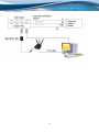
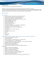
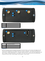
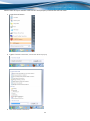
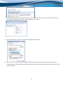
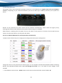
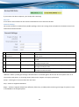
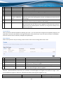
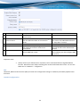
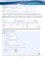
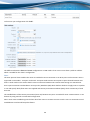
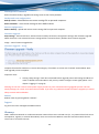
USER MANUAL 1 Legal notice Copyright © 2012 TELTONIKA Ltd. All rights reserved. Reproduction, transfer, distribution or storage of part or all of the contents in this document in any form without the prior written permission of TELTONIKA Ltd is prohibited. The manufacturer reserves the right to modify the product and manual for the purpose of technical improvement without prior notice. Other product and company names mentioned herein may be trademarks or trade names of their respective owners. Attention Before using the device we strongly recommend reading this user manual first. Do not rip open the device. Do not touch the device if the device block is broken. All wireless devices for data transferring may be susceptible to interference, which could affect performance. The device is not water-resistant. Keep it dry. Device is powered by low voltage +9V DC power adaptor. 2 Table of Contents Legal notice ........................................................................................................................................................................ 2 Attention ............................................................................................................................................................................ 2 SAFETY INFORMATION ...................................................................................................................................................... 5 Introduction ....................................................................................................................................................................... 7 Specifications: ................................................................................................................................................................ 7 LAN and Wi-Fi: ........................................................................................................................................................... 7 WiMAX (RUT523, RUT525, RUT535, RUT538, RUT523U, RUT525U, RUT535U, RUT538U): ..................................... 7 Electrical, Mechanical & Environmental: ................................................................................................................... 8 Setting up your router ....................................................................................................................................................... 9 Installation ..................................................................................................................................................................... 9 Front Panel ................................................................................................................................................................. 9 Back Panel ................................................................................................................................................................ 10 Logging in ..................................................................................................................................................................... 10 Operation Modes ............................................................................................................................................................. 15 Function explanations...................................................................................................................................................... 17 Status ........................................................................................................................................................................... 17 System Information ................................................................................................................................................. 17 Network Information ............................................................................................................................................... 18 Routes ...................................................................................................................................................................... 22 Realtime Graphs ...................................................................................................................................................... 22 Network ....................................................................................................................................................................... 27 Wan .......................................................................................................................................................................... 27 LAN ........................................................................................................................................................................... 33 Wireless ................................................................................................................................................................... 35 Backup WAN ............................................................................................................................................................ 38 Firewall..................................................................................................................................................................... 40 Static Routes ............................................................................................................................................................ 42 Diagnostics ............................................................................................................................................................... 43 Services ........................................................................................................................................................................ 43 PING Reboot ............................................................................................................................................................ 43 NTP ........................................................................................................................................................................... 44 Dynamic DNS............................................................................................................................................................ 45 3 OpenVPN.................................................................................................................................................................. 46 IPsec ......................................................................................................................................................................... 49 GRE Tunnel............................................................................................................................................................... 51 Systems ........................................................................................................................................................................ 53 Configuration Wizard ............................................................................................................................................... 53 Administration ......................................................................................................................................................... 55 Administration properties ....................................................................................................................................... 55 Backup and Firmware .................................................................................................................................................. 56 Reboot...................................................................................................................................................................... 56 Logout .......................................................................................................................................................................... 56 Glossary: .......................................................................................................................................................................... 56 4 SAFETY INFORMATION In this document you will be introduced on how to use a RUT5XX/RUT5XXU router safely. We suggest you to adhere to the following recommendations in order to avoid personal injuries and or property damage. You have to be familiar with the safety requirements before using the device! To avoid burning and voltage caused traumas, of the personnel working with the device, please follow these safety requirements. The device is intended for supply from a Limited Power Source (LPS) that power consumption should not exceed 15VA and current rating of overcurrent protective device should not exceed 2A. The highest transient overvoltage in the output (secondary circuit) of used PSU shall not exceed 71V peak. The device can be used with the Personal Computer (first safety class) or Notebook (second safety class). Associated equipment: PSU (power supply unit) (LPS) and personal computer (PC) shall comply with the requirements of standard EN 60950-1. Do not mount or service the device during a thunderstorm. To avoid mechanical damages to the device it is recommended to transport it packed in a damageproof pack. Protection in primary circuits of associated PC and PSU (LPS) against short circuits and earth faults of associated PC shall be provided as part of the building installation. To avoid mechanical damages to the device it is recommended to transport it packed in a damage-proof pack. While using the device, it should be placed so, that its indicating LEDs would be visible as they inform in which working mode the device is and if it has any working problems. Protection against overcurrent, short circuiting and earth faults should be provided as a part of the building installation. Signal level of the device depends on the environment in which it is working. In case the device starts working insufficiently, please refer to qualified personnel in order to repair this product. We recommend forwarding it to a repair centre or the manufacturer. There are no exchangeable parts inside the device. 5 Device connection 6 Introduction Thank you for purchasing a RUT5XX/RUT5XXU WiMAX router! RUT5XX is a series of compact mobile routers with high speed wireless and Ethernet connections. This router is ideal for people who‘d like to share their internet on the go, as it is not restricted by a cumbersome cable connection. Unrestricted, but not forgotten: the router still supports internet distribution via a broadband cable, simply plug it in to the wan port, set the router to a correct mode and you are ready to browse. Specifications: LAN and Wi-Fi: Wireless AP, Router, 4-Port Switch and Firewall in one device High performance 320 MHz CPU with 256 Mbits SDRAM IEEE 802.11b/g/n, IEEE 802.3, IEEE 802.3u standards 64/128-bit WEP, WPA, WPA2, WPA&WPA2 encryption methods 3xLAN 10/100Mbps Ethernet ports 1xWAN 10/100Mbps Ethernet port Supports Auto MDI/MDIX Remote/local Web management 1x 5dBi wireless antenna SSID stealth mode and access control based over MAC address System log to record the status of the Router Auto negotiation/manual mode for IEEE 802.11b/g/n Dynamic DNS LAN access control over Internet connection Virtual server Auto wireless channel selection OpenVPN IPSec Backup WAN Ping reboot WiMAX (RUT523, RUT525, RUT535, RUT538, RUT523U, RUT525U, RUT535U, RUT538U): Standard Compliant IEEE 802.16e-2005 Air Interface S-OFDMA Frequency Band 2.3 – 2.4GHz (RUT523), 2.5 – 2.7GHz (RUT525), 3.3 – 3.6GHz (RUT535) or 3.3 – 3.8GHz (RUT538) Channel Bandwidth 3 MHz, 3.5 MHz, 5 MHz, 6 MHz, 7 MHz, 8.75 MHz and 10 MHz Modulation Adaptive QPSK, 16QAM, 64QAM MIMO MRC, Matrix A + MRC, Matrix B Beamforming All I/O Beamforming Items RF Output Power 2x25 dBm @ 2.3-2.7GHz; 2x23dBm @ 3.3-3.8GHz RX Sensitivity: QPSK1/2: -99.5 @ 2.5 GHz, 10 MHz BW 16QAM1/2: -94.29 @ 2.5 GHz, 10 MHz BW QPSK1/2: -99 @ 3.5 GHz, 10 MHz BW 16QAM1/2: -93.8 @ 3.5 GHz, 10 MHz BW Antenna Gain 5 dBi @ 2.5 GHz, 3.5 GHz (RUT5xxU - 2 dBi) Antenna Type External dipole (RUT5xxU - internal) Handover Hard / Optimized Handover QoS Mechanism UGS, Real-Time-VR, Non Real-Time-VR, Best Effort, ERT-VR 7 Authentication EAP-TLS, EAP-TTLS-MSCHAPv2 Encryption 3 CCM-Mode 128-bit AES Error Handling HARQ UL and DL, up to Category 7 Electrical, Mechanical & Environmental: Dimensions (H x W x D) 100mm x 85mm x 36mm Weight 210 - 260g Power Supply 100 – 240 VAC -> 9 VDC wall adapter Input voltage range: 7 – 30 VDC Power Consumption < 7W Antenna connectors 2 x RP-SMA for WiMAX, 1 x RP-SMA for WiFi Indicators 4 x Ethernet LEDs, 1 x Power LED, 1 x WiMAX LED Operating Temperature 0C to +50C Storage temperature -20C to +70C Operating Humidity 10% to 90% Non-condensing Storage humidity 5% to 95% Non-condensing * – New hardware revision has 7 – 30VDC written on the device sticker while older revision has 9V – 1A 8 Setting up your router Installation After you unpack the box, follow the steps, documented below, in order to properly connect the device. For better WiFi performance, put the device in clearly visible spot, as obstacles such as walls and door hinder the signal. 1. First assemble your router by attaching the necessary antennas. If you have bought the RUT5XXU and a WiMAX dongle – plug the dongle into the USB Port, which is located on the back panel. 2. To power up your router, please use the power adapter included in the box. (IMPORTANT: Using a different power adapter can damage and void the warranty for this product.). 3. If you have a wired broadband connection you will also have to connect it to the WAN port of the router. Front Panel 1 2,3,4 5 6 7,8,9 10 Power socket LAN Ethernet ports WAN Ethernet ports Power LED LAN LEDs WAN LED 9 Back Panel RUT5XX 1, 3 2 4 5 WiMAX antenna connectors Wi-Fi antenna connector Reset button WiMAX LED RUT5XXU 1 2 3 4 Wi-Fi antenna connector Reset button WiMAX LED USB Port Logging in After you’re complete with the setting up as described in the section above, you are ready to start logging into your router and start configuring it. This example shows how to connect on Windows 7. On windows Vista: click Start -> Control Panel -> Network and Sharing Centre -> Manage network Connections -> (Go to step 4). On Windows XP: Click Start -> Settings -> Network Connections -> (see step 4) -> You wont’s see “Internet protocol version 4(TCP/IPv4)”, instead you’ll have to select “TCP/IP Settings” and click options -> (Go to step 6) 10 We first must set up our network card so that it could properly communicate with the router. 1. Press the start button 2. Type in “network connections”, wait for the results to pop up. 3. Click “View network connections” 11 4. Then right click on your wireless device that you use to connect to other access points (It is the one with the name “Wireless Network Connection” and has signal bars on its icon). 5. Select Internet Protocol Version 4 (TCP/IPv4) and then click Properties 6. By default the router is going to have DHCP enabled, which means that if you select “Obtain an IP address automatically” and “Obtain DNS server address automatically”, the router should lease you an IP and you should be ready to login. 12 7. If you choose to configure manually here’s what you do: First select an IP address. Due to the stock settings that your router has arrived in you can only enter an IP in the form of 192.168.1.XXX , where XXX is a number in the range of 2-254 (192.168.1.2 , 192.168.1.254 , 192.168.1.155 and so on… are valid; 192.168.1.0 , 192.168.1.1 , 192.168.1.255 , 192.168.1.699 and so on… are not). Next we enter the subnet mask: this has to be “255.255.255.0”. Then we enter the default gateway: this has to be “192.168.1.1”. Finally we enter primary and secondary DNS server IPs. One will suffice, though it is good to have a secondary one as well as it will act as a backup if the first should fail. The DNS can be your routers IP (192.168.1.1), but it can also be some external DNS server (like the one Google provides: 8.8.8.8). 13 Right click on the Wireless network icon and select Connect / Disconnect. A list should pop up with all available wireless networks. Select “Teltonika” and click connect. Then we launch our favourite browser and enter the routers IP into the address field: Press enter. If there are no problems you should be greeted with a login screen such as this: 14 Enter the default password, which is “admin01” into the “Password” field and then either click Login with your mouse or press the Enter key. You have now successfully logged into the router and should see the Status page. From here on out you can configure almost any aspect of your router. Operation Modes The RUT5XX/RUT5XXU router supports various operation modes. It can be connected to the internet (WAN) via WiMAX, standard Ethernet cable or via a wireless network. If you connect to the internet via an Ethernet cable of Wi-Fi, you may also backup your connection with WiMAX for added stability. On every case except when you connect to the internet via Wi-Fi, you can distribute your internet via an Ethernet cable (3 ports) and/or a wireless network. When you connect via Wi-Fi, you cannot have Wi-Fi in your LAN. WAN WiMAX Ethernet Wi-Fi LAN Ethernet √ √ √ WiMAX Backup link Wi-Fi √ √ x x √ √ In later sections it will be explained, bit by bit, how to configure your router to work in a desired mode. 15 Powering Options The RUT5xx router can be powered from power socket (1) or over Ethernet port (applies only to the new hardware revision*). Depending on your network architecture you can use LAN 3 (2) or WAN (3) Ethernet port to power the device. RUT5xx can be powered from power socket and over Ethernet simultaneously. Power socket has higher priority meaning that the device will draw power from power socket as long as it is available. When RUT5xx is switching from one power source to the other it loses power for a fraction of the second and may reboot. The device will function correctly after the reboot. Do not use LAN3 and WAN port for powering RUT5xx simultaneously. Use pins 4 and 5 of Ethernet port to supply posite voltage and connect pins 7 and 8 ground. Though the device can be powered over Ethernet port it is not compliant with IEEE 802.3af-2003 standard. Powering RUT5xx from IEEE 802.3af-2003 power supply will damage the device as it is not rated for input voltages of PoE standard. * – New hardware revision has 7 – 30VDC written on the device sticker while older revision has 9V – 1A 16 Function explanations The following sections contain a detailed explanation of every page, tab and sub tab of the configuration interface in the order that they appear on the router. Status The status section contains various information, like current IP addresses of various network interfaces; the state of the routers memory; firmware version; DHCP leases; associated wireless stations; graphs indicating load, traffic, etc.; and much more. System Information The System Information tab contains data that pertains to the routers operating system. System 1. 2. 3. Field Name Router Name Router Model Firmware Version Sample value Teltonika Teltonika RUT5xx RUT5XX_T_00.00.436 4. Kernel Version 3.2.15 5. Local Time 6. Uptime Fri Jun 29 16:38:48 2012 4h 29m 3s 7. Load Average 0.98, 0.57, 0.30 Explanation Name of the router (hostname of the routers system). Routers model. Shows the version of the firmware that is currently loaded in the router. Newer versions might become available as new features are added. Use this field to decide whether you need a firmware upgrade or not. The version of the Linux kernel that is currently running on the router. Shows the current system time. Might differ from your computer, because the router synchronizes it's time with an NTP server. Indicates how long it has been since the router booted up. Reboots will reset this timer to 0. Indicates how busy the router is. Let's examine some sample output: "2.43, 2.96, 3.41". The first number 2.43 means that in the past minute there have been, on average, 2.43 processes running or waiting for a resource. The second number show that in the past 10 minutes, on average, there have been 2.96 processes 17 running or waiting for a resource. The last number indicates the same on the last 15 minutes. Memory Field Name 1. Total Available 2. Free Sample Value 14416/29964 1476/29964 3. Cached 9868/29964 4. Buffered 3072/29964 Explanation Shows how much memory is available to maintain routers functionality. The amount of memory that is completely free. Should this rapidly decrease or get close to 0, it would indicate that the router is running out of memory, which could cause crashes and unexpected reboots. The size of the area of memory that is dedicated to storing frequently accessed data. The size of the area in which data is temporarily stored before moving it to another location. Network Information This page is much like the status page, previously described, though dedicated to data associated with networking. WiMAX Statistics for the WiMAX module and the connection. 1. 2. 3. 4. 5. 6. 7. Field Name Uptime State Signal strength MAC address Uplink Modulation Downlink Modulation Version Explanation The uptime of the WiMAX module. Shows the state of the connection. Indicates connection strength. The MAC address of the WiMAX module (and effectively, your routers on the WiMAX network). Type of modulation used when sending information. Type of modulation used when receiving information. WiMAX module version. WAN Statistics on the routers WAN connection. 18 1. 2. 3. 4. 5. Field Name Interface Sample Value WiMAX Type IPv4 address Netmask* Gateway* DHCP 82.140.177.32 Explanation Specifies through what medium the router is connecting to the internet. This can either be Wired, WiMAX or Wi-Fi. Specifies the type of connection. This can either be static or DHCP. The IP address that the routers uses to connect the internet. 255.255.255.240 10.12.104.97 Indicates the networks netmask Indicates the default gateway, an address where traffic destined for the internet is routed to. 6. DNS#* 8.8.8.8 Domain name server(s). 7. Expires** 1h 57m 25s The amount of time before the routers DHCP lease expires. 8. Connected* 0h 2m 2s How long the connection has been successfully maintained. *-These fields show up on other connection modes. **-Exclusive to other Modes with DHCP. LAN Field Name IPv4 address Netmask Connected 1. 2. 3. Sample Value 192.168.1.161 255.255.255.0 0h 6m 14s Explanation Address that the router uses on the LAN network. Indicates the networks netmask. How long LAN has been successfully maintained. Wireless Wireless can work in two modes, AP or Client. AP is when the wireless radio is used to create an Access Point that other devices can connect to. Client is when the radio is used to connect to an Access Point via WAN. Client 1. Field Name SSID Sample Value Explanation teltonika_rnd_division_ap The SSID that the AP, to which the routers is connected to, uses. 19 2. Mode Client 3. Channel 6 (2.44 GHz) 4. 5. BSSID Encryption C8:3A:53:02:FC:B0 WPA2 PSK (CCMP) 6. Bit rate 65.0 MBit/s 7. Country LT Connection mode – Client indicates that the router is a client to some local AP. The channel that the AP, to which the routers is connected to, uses. Your wireless radio is forced to work in this channel in order to maintain the connection. The MAC address of the access points radio. The AP, to which the router is connected to, dictates the type of encryption. The physical maximum possible throughput that the routers radio can handle. Keep in mind that this value is cumulative - The bitrate will be shared between the router and other possible devices that connect to the local AP. Country code. AP 1. Field Name Signal Quality 2. SSID 3. 4. Mode Channel 5. 6. BSSID Encryption 7. Bit rate 8. Country Sample Value 100% Explanation The quality between routers radio and some other device that is connecting to the router. Will show 0% if no devices are trying to connect or are currently maintaining a connection. Teltonika_demo The SSID that is being broadcast. Other devices will see this and will be able to use to connect to your wireless network. Master Connection mode – Master indicates that you router is an access point. 6 (2.44 GHz) The channel which is used to broadcast the SSID and to establish new connections to devices. 00:0C:43:30:50:38 MAC address of your wireless radio. WPA2 PSK The type of encryption that the router will use to authenticate, establish and (CCMP) maintain a connection. 1.0 MBit/s The bitrate will be shared between all devices that connect to the routers wireless network. LT Country code. Additional note: MBit/s indicates the bits not bytes. To get the throughput in bytes divide the bit value by 8, for e.g. 54MBits/s would be 6.75MB/s (Mega Bytes per second). Associated Stations Outputs a list of all devices and their MAC addresses that are maintain a connection with your router right now. This can either be the information of the Access Point that the router is connecting to in Client Mode OR a list of all devices that are connecting to the router in Access Point mode: 20 DHCP Leases If you have enabled a DHCP server this field will show how many devices have received an IP address and what those IP addresses are. The picture above shows a DHCP lease for an Android phone that is currently connecting to the routers Access Point. Backup WAN When enabled this field will indicate the health of your primary connection: IN USE READY NOT READY Indicates that the connection is being used for main traffic. Indicates that the connection is ready to take over network traffic, if the other link should fail. Indicates that the connection is down. More on this see the main backup WAN section of this manual. 21 Routes ARP Shows the routers active ARP table. An ARP table contains recently cached MAC addresses of every immediate device that was communicating with the router. Active IPv4-Routes Shows the routers routing table. The routing table indicates where a TCP/IP packet, with a specific IP address, should be directed to. Realtime Graphs Real-time graphs show how various statistical data changes over time. Load 22 This tri-graph illustrates average system load over the course of ~3 minutes; each new measurement is taken every 3 seconds. The graph consists out of three colour coded graphs, each one corresponding to the average system load over 1 (red), 5 (orange) and 15 (yellow) most recent minutes. Although not graphed, the page also displays peak loads over 1, 5 and 15 minutes. Traffic Bridge Cumulative graph, which encompasses wired Ethernet LAN and the wireless network. LAN+WAN 23 Graphs the total traffic that passes through both WAN and LAN network interfaces. LAN Indicates how much traffic has been passed through your Ethernet LAN network. WAN(x) Graphs the amount of traffic which passed through the current active WAN connection. 24 Wi-Fi Shows the amount of traffic that has been sent and received through the wireless radio. Wireless This graph illustrates how signal strength and the amount of noise change over time. 25 This graph illustrates how the physical rate of wireless changes over time. Connections This graph shows a concise history of the amount of connections that the router maintained. Blue graph indicates UDP connections, green TCP and red other types (ICMP, etc…). Other values indicate each respective graphs average and peak connection amounts over 3 minutes. 26 On the same page you can also analyse a detailed list of all active connections that the router maintains. Each entry consist of a type of network (“IPV4”), protocol (TCP, UDP, ICMP), the source address (an IPv4 address + the source port), the destination address (an IPv4 address + the destination port) and how much traffic has gone through that particular connection: it’s size in Bytes and the amount of packets. Network Wan WAN configuration is, arguably, the crux of the routers configuration as it determines how the router will connect to the internet. Here is quick rundown of how the page looks and what each field means. Operation Mode First and foremost a mode of connection has to be defined. Available selections: 1. 2. 3. Type Wired Wifi WiMAX Description An Ethernet cable connected to the WAN port of the router. The router will be able to connect to a local wireless access point and reach the internet through it. The router will connect to your local WiMAX network for internet access. 27 Common configuration Common configuration allows you to configure your TCP/IP settings for the wan network. You can switch between the Static, DHCP or PPPoE protocol by selecting the protocol that you want to use and then pressing Switch Protocol General This area is dedicated for protocol specific options. Static: This is the configuration setup for when you select the static protocol. 1. 2. 3. 4. Filed name IPv4 address IPv4 netmask IPv4 gateway IPv4 broadcast Sample 192.168.99.162 255.255.255.0 192.168.99.254 192.168.99.255 5. custom DNS servers 8.8.8.8 8.8.6.6 Explanation Your routers address on the WAN network A mask used to define how “large” the WAN network is Address where the router will send all the outgoing traffic Broadcast address (autogenerated if not set). It is best to leave this blank unless you know what you are doing. Usually the gateway has some predefined DNS servers. As such the router, when it needs to resolve a hostname (“www.google.com”, “www.cnn.com”, etc…) to an IP address, it will forward all the DNS requests to the gateway. By entering custom DNS servers the router will take care of host name resolution. You can enter multiple DNS servers to provide redundancy in case the one of the server fails. 28 DHCP: When you select the DHCP protocol you can use it as is, because most networks will not require any additional advanced configuration. PPPoE. This protocol is mainly used by DSL providers: This is the configuration setup for when you select PPPoE protocol. 1. 2. 3. 4. Filed name PAP/CHAP username PAP/CHAP password Access Concentrator Service Name Sample test your_password isp isp Explanation Your username and password that you would use to connect to your carriers network. Specifies the name of access concentrator. Leave empty to autodetect. Specifies the name of the service. Leave empty to autodetect. Advanced These are the advanced settings for each of the protocols, if you are unsure of how to alter these attributes it is highly recommended to leave them to a trained professional: 29 Static: 1. Field name Bring up on boot Sample value On 2 3. Disable NAT Override MAC address On/Off 00:0C:43:30:50:38 4. Override MTU 1500 5. Use gateway metric 0 Explanation Specifies whether the interface will be configured and brought up when the router boots up. Disabling will render your WAN connection non-functional Toggle NAT on and off. Override MAC address of the WAN interface. If your ISP gives you a static IP address it might also bind it to your computers MAC address (i.e. that IP will only work with your computer). In this field you can enter your computers MAC address and fool the gateway in thinking that it is communicating with your computer. Maximum transmission unit – specifies the largest possible size of a data packet. The WAN configuration by default generates a routing table entry. With this field you can alter the metric of that entry. DHCP: 30 PPPoE: IP Aliases IP aliases are a way of defining or reaching a subnet that works in the same space as the regular network. As you can see, the configuration is very similar to the static protocol; only in the example a 55’th subnet is defined. Now if some device has an IP in the 55 subnet (192.168.55.xxx) and the subnets gateway metric is “higher” and the device is trying to reach the internet it will reroute it’s traffic not to the gateway that is defined in common configurations but through the one that is specified in IP aliases. 31 You may also optionally define a broadcast address and a custom DNS server. WiMAX If you have selected WiMAX to be your primary means of connecting to the internet, you will also be granted additional control over the WiMAX module: Field Name Reboot WiMAX modem Turn on/off WiMAX Explanation 1. Pressing this button will reboot the WiMAX module. 2. Pressing this button will either turn on or off the connection to any available WiMAX network. These buttons differ from any other in a way that they make alterations to the WiMAX module directly, instead of the router. How do I setup Wifi WAN? First we must switch the mode to Wifi. Do so by selecting Wifi from the list and wait for the page to quickly reload. Now you have a selection of protocols available for you. Depending on whether the Access Point that you intend to connect to runs a DHCP server or not, you will have to choose DHCP or Static (AP runs a DHCP server – DHCP; Does not run - Static). When you’ve configured your protocol settings press Save and wait until the settings are applied. Next, goto the Network -> Wireless page and wait until it loads (For the first time an automatic Site Survey will be initiated). You should now see a list of available, local Access Points. Choose one and click Join Network. Should you be asked enter the secret Encryption Key and click Submit. 32 Now you should be transported to the Wireless Station page. Click Save and wait until all the settings are applied. The configuration is complete and you should now be able to access the internet. LAN This page is used to configure the LAN network, where all your devices and computers that you connect to the router will reside. The common configuration and IP aliasing sections are identical to the ones found in WAN, so for an explanation on how they work please follow through there. DHCP Server The DHCP server is the router side service that can automatically configure the TCP/IP settings of any device that requests such a service. If you connect a device that has been configured to obtain IP address automatically the DHCP server will lease an address and the device will be able to fully communicate with the router. 33 1. 2. Field Name Disable Start 3. Limit 4. Lease time Sample value Explanation Checked/unchecked Check to DISABLE the DHCP server. 100 The starting address of the range that the DHCP server can use to give out to devices. E.g.: if your LAN IP is 192.168.2.1 and your subnet mask is 255.255.255.0 that means that in your network a valid IP address has to be in the range of [192.168.2.1 – 192.168.2.254](192.168.2.0 and 192.168.2.255 are special unavailable addresses). If the Start value is set to 100 then the DHCP server will only be able to lease out addresses starting from 192.168.2.100 150 How many addresses the DHCP server gets to lease out. Continuing on the above example: if the start address is 192.168.2.100 then the end address will be 192.168.2.254 (100 + 150 – 1 = 254). 12h How long can a leased IP be considered valid. An IP address after the specified amount of time will expire and the device that leased it out will have to request for a new one. Advanced settings You can also define some advanced options that specify how the DHCP server will operate on your LAN network. 1. Field Name Sample Value Dynamic DHCP Checked/Unchecked 2. Force Checked/Unchecked 3. IPv4 netmask 255.255.255.0 Explanation Dynamically allocate client addresses, if set to 0 only clients present in the ethers files are served Forces DHCP serving even if another DHCP server is detected on the same network segment. You can override your LAN netmask here to make the DHCP server think it’s serving a larger or a smaller network than it actually is. 34 4. DHCP-Options 6,192.168.2.1,192.168.2.2 Additional options to be added for this DHCP server. For example with 26,1470 '26,1470' or 'option:mtu, 1470' you can assign an MTU per DHCP. option:mtu, 1470 Your client must accept MTU by DHCP for this to work. Wireless On this page you can configure your wireless settings. Depending on whether your WAN mode is set to Wifi or not, the page will display either the options for configuring an Access Point or options for configuring a connection to some local access point. Access Point: Here you can see the Overview of the wireless configuration. It is divided into two main sections – device and interface. One is dedicated to configuring hardware parameters other – software. Device General Here you can toggle the availability of the wireless radio and the physical channel frequency. Important note: As seen in the picture you should always Save before toggling the radio on and off. 35 Advanced Here you can configure more advanced parameters: 1. Field name Mode Sample value Auto, b, g, g+n 2. Country Code 3. 4. Distance Optimization Frag. Threshold Any ISO/IEC 3166 alpha2 country code 100 2346 5. RTS/CTS Threshold 2346 Explanation Different modes provide different throughput and security options. Selecting this will help the wireless radio configure its internal parameters to meet your countries wireless regulations. Distance to farthest network member in meters. The smallest packet size that can be fragmented and transmitted by multiple frames. In areas were interference is a problem, setting a lower fragment threshold might help reduce the probability of unsuccessful packet transfers, thus increasing speed. Request to send threshold. It can help resolve problems arising when several access points are in the same area, contending. Interface General ESSID – Your wireless networks identification string. This is the name of your Wi-Fi network. When other Wi-Fi capable computers or devices scan the area for Wi-Fi networks they will see your network with this name. Hide ESSID – Will render your SSID hidden from other devices that try to scan the area. 36 Security Encryption – There are many modes of encryption, though two distinctive classes have to pointed out. WEP Enter the keys that will be used as passphrase for connecting computers and then specify which key will be preferred above the remaining. It’s sufficient to enter one key and then specify it as the preferred one. Length is important as well: 10 or 26 characters in length in hex mode OR 5 or 13 in ASCII mode. A hex key may only contain numbers ‘0’ through ‘9’ and letters ‘a’ through ‘f’. WPA First select an encryption method: TKIP, CCMP, TKIP&CCMP, auto. Note: Some authentication methods won’t support TKIP (and TKIP&CCMP) encryption. After you’ve selected your encryption method, you should enter your passphrase, which must be at least 8 characters long. 37 MAC-Filter Filter – you can define a rule for what to do with the MAC list you’ve defined. You can either allow only the listed MACs or allow ALL, but forbid only the listed ones. Client Client mode is nearly identical to AP, except for the fact that most for the options are dictated by the wireless access point that the router is connecting to. Changing them can result in an interrupted connection to an AP. In addition to standard options you can also click the Scan button to rescan the surrounding area and attempt to connect to a new wireless access point. Backup WAN Backup WAN is function that allows you to back up your wired OR wireless connection in case they go down. At the current moment you can only backup wired/Wifi with WiMAX. The majority of the options consist of timing and other important parameters that help determine the health of your primary connection. Regular health checks are constantly performed in the form of ICMP packets (PINGs) on the your primary connection. When the connections state starts to change (READY->NOT READY and vice versa) a necessary 38 amount of failed or passed health checks has to be reached before the state changes completely. This delay is instituted so as to mitigate “spikes” in connection availability, but it also extends the time before the backup link can be brought up or down. 1. Field Name Health Monitor Interval Sample value Dsb/5/10/20/30/60/120 Seconds 2. Health Monitor ICMP HOST Dsb/DNS/WAN GW/Custom 3. Health Monitor ICMP Timeout ½/3/4/5/10 Seconds 4. Attempts Before WAN Failover 1/3/5/10/15/20 5. Attempts Before WAN Recovery 1/3/5/10/15/20 6. DNS Servers Auto/Custom 7. Backup ICMP host IPv4 address The interval at which health checks are performed Where to PING for a health check. As there is no definitive way to determine when the connection to internet is down for good, you’ll have to define a host whose availability that of the internet as a whole. How long to wait for an ICMP request to come back. Set a higher value if your connection has high latency or high jitter (latency spikes). How many checks should fail for your WAN connection to be declared DOWN for good. How many checks should pass for your WAN connection to be declared UP. Define custom DNS servers. Has meaning when you select DNS as your Health Monitor ICMP HOST. This is where the address of an ICMP host, that will be used to check the health of your WiMAX backup link, goes. This has to be a ping-able host. How do I set up a backup link? First we must pick a main link: Wired or Wi-Fi, and ensure that the link is working. Configure your WAN settings to use that link and see whether you have internet access. If the main link is working we can continue configuring our Backup Link. Now, go to Backup WAN page and configure the settings to your liking. Click Save and wait until the settings are applied. Now in the Status -> Network Information page there should be a status indication for the backup WAN. If everything is working correctly you should see this: The above picture shows the status for Backup WAN configured on a wired main link. You can now simulate a downed link by simply unplugging your Ethernet WAN cable. When you’ve done so you should see this: And, if you plug the cable back in you should, again, see this: 39 If you witness the above sequence, your backup link is working! Firewall In this section we will look over the various firewall features that come with RUT5xx. General Settings The routers firewall is a standard linux iptables package, which uses routing chains and policies to facilitate control over inbound and outbound traffic. 2. Field name Enable SYN-flood protection Drop Invalid packets 3. Input 4. Output 5. Forward 1. Sample value Explanation Checked/Unchecked When checked the router becomes more resistant against SYNflood attacks. Checked/Unchecked A “Drop” action is performed on a packet that is determined to be invalid Reject/Drop/Accept DEFAULT* action that is to be performed for packets that pass through the Input chain. Reject/Drop/Accept DEFAULT* action that is to be performed for packets that pass through the Output chain. Reject/Drop/Accept DEFAULT* action that is to be performed for packets that pass through the Forward chain. *DEFAULT: When a packet goes through a firewall chain it is matched against all the rules for that specific chain. If no rule matches said packet, an according Action (either Drop or Reject or Accept) is performed. Accept – Packet gets to continue down the next chain. Drop – Packet is stopped and deleted. Reject – Packet is stopped, deleted and, differently from Drop, an ICMP packet containing a message of rejection is sent to the source of the dropped packet. 40 DMZ By enabling DMZ for a specific internal host (for e.g.: your computer), you will expose that host and its services to the routers WAN network (i.e. - internet). Port Forwarding Here you can define your own port forwarding rules. You can use port forwarding to set up servers and services on local LAN machines. The above picture shows how you can set up a rule that would allow a website that is being hosted on 192.168.99.156, to be reached from the outside by entering http://routersExternalIp:12345/ . Explanation Name of the rule. Used purely to make it easier to manage rules. Type of protocol of incoming packet. From what port on the WAN network will the traffic be forwarded. 4. Internal IP address IPv4 address of some The IP address of the internal machine that hosts some service computer on your LAN that we want to access from the outside. 5. Internal port 1-65535 To what port on the internal machine would the rule redirect the traffic. Additional note: Notice how the external port is 12345 and not 80. It is perfectly fine to define the external port as 80, but then the routers configuration interface would not reachable (unless you change the web access port from remote management). 1. 2. 3. Field name Name Protocol External Port Sample value “localWebsite” TCP/UDP/TCP+UDP/Other 1- 65535 When you click edit you can fine tune a rule to near perfection, if you should desire that. Traffic Rules The traffic rule page contains a more generalised rule definition. With it you can block or open ports, alter how traffic is forwarded between LAN and WAN and many more things. 41 1. 2. 3. 4. 5. 6. Field Name Name Family Protocol Source Destination Action 7. Enable Sample Value “ruleName” IPv4 TCP/UDP/Other… IPv4 address IPv4 address Drop/Accept/Reject + chain + additional rules Checked/Unchecked 8. Sort Up/Down Explanation Used to make rule management easier Only IPv4 is currently supported Protocol of the packet that is being matched against traffic rules. The source of the packet. The destination of the packet Action to be taken on the packet if it matches the rule. You can also define additional options like limiting packet volume, and defining to which chain the rule belongs Self-explanatory. Uncheck to make the rule inactive. The rule will not be deleted, but it also will not be loaded into the firewall. When a packet arrives, it gets checked for a matching rule. If there are several rules that match the rule, the first one is applied i.e. the order of the rule list impacts how your firewall operates, therefore you are given the ability to sort your list as you wish. Custom Rules Here you have the ultimate freedom in defining your rules – you can enter them straight into the iptables program. Just type them out into the text field ant it will get executed as a linux shell script. If you are unsure of how to use iptables, check the internet out for manuals, examples and explanations. Static Routes Static routes provide a way of entering custom entries in the internal routing table of the router. Field name Interface Target IPv4-Netmask Explanation 1. The zone where the ‘Target’ resides 2. The source of the traffic. 3. Mask that is applied to the Target to determine to what actual IP addresses the routing rule applies 4. IPv4-Gateway IPv4 address To where the router should send all the traffic that applies to the rule 5. Metric integer Used as a sorting measure. If a packet about to be routed fits two rules, the one with the higher metric is applied. Additional note on Target & Netmask: You can define a rule that applies to a single IP like this: Target - some IP; Netmask - 255.255.255.255. Furthermore you can define a rule that applies to a segment of IPs like this: Target – some IP that STARTS the segment; Netmask – Netmask that defines how large the segment is. E.g.: 192.168.55.161 192.168.55.0 Value Lan/wan IPv4 address IPv4 mask 255.255.255.255 255.255.255.0 Only applies to 192.168.55.161 Applies to IPs in range 192.168.55.042 192.168.55.240 255.255.255.240 192.168.55.161 192.168.0.0 255.255.255.0 255.255.0.0 192.168.55.255 Applies 192.168.55.240 192.168.55.255 192.168.55.0 - 192.168.55.255 192.168.0.0 - 192.168.255.255 Diagnostics Contains Network Utilities used for testing network. Ping – the utility used to test the reachability of a host on an Internet IP network and to measure the round-trip time for messages sent from the originating host to a destination server. Enter server IP address or hostname and click “Ping”. Server echo response will be shown after few seconds if server is accessible. Traceroute – diagnostic tool for displaying the route (path) and measuring transit delays of packets across an Internet IP network. Enter server IP address or hostname and click “Traceroute”. Log containing route information will be shown after few seconds. Nslookup – network administration command-line tool for querying the Domain Name System (DNS) to obtain domain name or IP address mapping or for any other specific DNS record. Enter server hostname and click “Nslookup”. Log containing specified server DNS lookup information will be shown after few seconds. Full manual with all available “Nslookup” commands and parameters can be found in Linux manual page nslookup(1). Important notes: Note that DNS server must be configured correctly if you use server hostname instead of server IP address in address field. Services PING Reboot PING Reboot function will periodically send PING command to server and waits for echo receive. If no echo is received router will try again sending PING command defined number times, after defined time interval. If no echo is received after the defined number of unsuccessful retries, router will reboot. It is possible to turn of the router rebooting after defined unsuccessful retries. Therefore this feature can be used as “Keep Alive” function, when router PINGs the host unlimited number of times. 43 Common configuration 1. Field name Enable PING Reboot 2. Reboot router if no echo received 3. 4. Interval between PINGs Retry count 5. Server to PING Description This check box will enable or disable PING reboot feature. This check box will disable router rebooting after the defined number of unsuccessful retries. Time interval in minutes between two PINGs. Number of times try sending PING to server after time interval if echo receive was unsuccessful. Server IP address or host name, which will receive PING from router Notes PING Reboot is disabled by default. This check box must be unselected if you want to use PING Reboot feature as “Keep Alive” function. Minimum time interval is 5 minutes. Minimum retry number is 1. Second retry will be done after defined time interval. If you use server host name instead of the IP address you must configure DNS server first. Important notes: Always check if your defined server responds to echo commands before using PING Reboot function. Otherwise router keeps rebooting after unsuccessful PING echo receive. You can test PING send at “Network” > “Diagnostics”. NTP Hostname, Network Time Protocol (NTP) and time zone configuration settings is needed to periodically update router local time. Common configuration 44 “Sync with browser” button will synchronize local router time with computer browser time. 1. 2. 3. 4. Field name Local Time Hostname Timezone Enable builtin NTP 5. NTP server candidates Description Local time of router. Hostname of router. Time zone of your country. This check box will turn on automatic time synchronizing with defined NTP servers. NTP server hostname. Notes ------When check box is selected you must enter one or more working NTP servers. Otherwise time sync feature will not work. You can add as many servers as you need by clicking “add” button at the end of server hostname field. Dynamic DNS Dynamic DNS (DDNS) is a domain name service allowing to link dynamic IP addresses to static hostname. To start using this feature firstly you should register to DDNS service provider. You are provided with add/delete buttons to manage and use different DDNS configurations at the same time! 45 1. 2. 3. 4. 5. 6. 7. 8. Field name Enable Status Service Hostname Username Password IP renew interval Force IP renew Explanation Enables current DDNS configuration. Your dynamic DNS service provider selected from the list: 1. dydns.org 2. 3322.org 3. no-ip.com 4. easydns.com 5. zoneedit.com In case your DDNS provider is not present from the ones provided, please feel free to use "custom" and add hostname of the update URL. Domain name which will be linked with dynamic IP address. Name of the user account. Password of the user account Time interval (in minutes) to check if the IP address of the device have changed. Time interval (in minutes) to force IP address renew. OpenVPN VPN (Virtual Private Network) is a method for secure data transfer through unsafe public network. This section explains how to configure OpenVPN, which is implementation of VPN supported by the RUT5XX router. 46 A picture above demonstrates default OpenVPN configurations list, which is empty, so you have to define a new configuration to establish any sort of OpenVPN connection. To create it, enter desired configuration name in “New configuration name” field, select device role from “Role” drop down list. For example, to create a OpenVPN client with configuration name Demo, select client role, name it “Demo” and press “Add New” button as shown in the following picture. A new configuration entry has appeared in the list and it is populated with default OpenVPN client settings. (You could select a server in previous step to create server default configuration). To see at specific configuration settings press “edit” button located in newly created configuration entry. A new page with detailed configuration appears, as shown in the picture below. You can set custom settings here according to your VPN needs. Below is a summary of parameters available to set: 47 1. 2. Field Name Enabled TUN/TAP 3. 4. 5. Protocol Port LZO 6. Authentication 7. 8. Remote host IP address Resolve Retry 9. Keep alive 10. Explanation Switches configuration on and off. This must be selected to make configuration active. Selects virtual VPN interface type. TUN is most often used in typical IP-level VPN connections, however, TAP is required to some Ethernet bridging configurations. Defines a transport protocol used by connection. You can choose here between TCP and UDP. defines TCP or UDP port number (make sure, that this port allowed by firewall). This setting enables LZO compression. With LZO compression, your VPN connection will generate less network traffic; however, this means higher router CPU loads. Use it carefully with high rate traffic or low CPU resources. Sets authentication mode, used to secure data sessions. Two possibilities you have here: “Static” means, that OpenVPN client and server will use the same secret key, which must be uploaded to the router using “Static pre-shared key” option. “Tls” authentication mode uses X.509 type certificates. Depending on your selected OpenVPN mode (client or server) you have to upload these certificates to the router: For client: Certificate Authority (CA), Client certificate, Client key. For server: Certificate Authority (CA), Server certificate, Server key and Diffie-Hellman (DH) certificate used to key exchange through unsafe data networks. All mention certificates can be generated using OpenVPN or OpenSSL utilities on any type host machine. Certificate generation and theory is out of scope of this user manual. IP address of OpenVPN server (applicable only for client configuration). Sets time in seconds to try resolve server hostname periodically in case of first resolve failure before generating service exception. Defines two time intervals: one is used to periodically send ICMP request to OpenVPN server, and another one defines a time window, which is used to restart OpenVPN service, if no ICPM request is received during the window time slice. IP address of virtual local network interface (applicable only for point to point connections). Local tunnel endpoint 11. Remote tunnel IP address of virtual remote network interface. endpoint 12. Remote IP address/subnet of remote virtual network. network IP address 13. Remote Subnet mask of remote virtual network. network IP netmask After setting any of these parameters press “Save” button. Some of selected parameters will be shown in the configuration list table. You should also be aware of the fact that router will launch separate OpenVPN service for every configuration entry (if it is defined as active, of course) so the router has ability to act as server and client at the same time. Server The difference between client and server configurations in TUN mode is that a server must have a public IP address which is needed for the client’s configuration. Other than that setting up a server is pretty much the same as setting up a client: Set the role as “Server”, enter a name for your configuration and then click Add New. After a while you should see this: 48 To fine tune your configuration click “Edit”. The difference between client and server configurations in TUN mode is that a server must have a public IP address which is needed for the client’s configuration. IPsec The IPsec protocol client enables the router to establish a secure connection to an IPsec peer via the Internet. IPsec is supported in two modes - transport and tunnel. Transport mode creates secure point to point channel between two hosts. Tunnel mode can be used to build a secure connection between two remote LANs serving as a VPN solution. IPsec system maintains two databases: Security Policy Database (SPD) which defines whether to apply IPsec to a packet or not and specify which/how IPsec-SA is applied and Security Association Database (SAD), which contain Key of each IPsec-SA. The establishment of the Security Association (IPsec-SA) between two peers is needed for IPsec communication. It can be done by using manual or automated configuration. Note: router starts establishing tunnel when data from router to remote site over tunnel is sent. For automatic tunnel establishment used tunnel keep alive feature. 49 Automatic IPSec Key exchange 1. 2. 3. 4. Field name Enable IPSec IPSec key exchange mode Enable NAT traversal Enable initial contact Explanation Check box to enable IPSec. Select the Manual or Automatic Key exchange. Enable this function if client-to-client applications will be used. Enable this to send an INITIAL-CONTACT message. 5. 6. Peers identifier type Mode 7. 8. My identifier Preshare key Choose “fqdn” or “user fqdn” accordingly to your IPSec server configuration. Select “Main” or “Aggressive” mode accordingly to your IPSec server configuration. Set the device identifier for IPSec tunnel. specify the authentication secret [string]. Secret’s length depends on selected algorithm, eg. 128 bit long secret is 16 characters in length, 128 bits / 8 bits (one character) = 16. 9. Remote VPN Endport set remote IPSec server IP address. 50 Phase 1 and Phase 2 must be configured accordingly to the IPSec server configuration. Remote Network Secure Group – Set the remote network (Secure Policy Database) information. 1. Field name Tunnel keep alive 2. 3. Ping IP address Ping period (seconds) Explanation Allows sending ICMP echo request (ping utility) to the remote tunnel network. This function may be used to automatically start the IPSec tunnel. Enter IP address to which ICMP echo requests will be sent. Set sent ICMP request period in seconds. GRE Tunnel GRE (Generic Routing Encapsulation RFC2784) is a solution for tunneling RFC1812 private address-space traffic over an intermediate TCP/IP network such as the Internet. GRE tunneling does not use encryption it simply encapsulates data and sends it over the WAN. 51 WAN IP: A.A.A.A WAN IP: B.B.B.B Internet Tunnel 10.0.0.1/24 LAN1 192.168.0.0/24 Tunnel 10.0.0.2/24 GRE tunnel LAN1 192.168.1.0/24 LAN2 192.168.1.2 192.168.0.2 In the example network diagram two distant networks LAN1 and LAN2 are connected. To create GRE tunnel the user must know the following parameters: 1. Source and destination IP addresses. 2. Tunnel local IP address 3. Distant network IP address and Subnet mask 1. 2. Field name Enable GRE Tunnel TTL 3. PMTUD 4. Remote tunnel network address Remote CIDR 5. Explanation Check the box to enable the GRE Tunnel function. Specify the fixed time-to-live (TTL) value on tunneled packets [0-255]. The 0 is a special value meaning that packets inherit the TTL value. Check the box to enable the Path Maximum Transmission Unit Discovery (PMTUD) status on this tunnel. Specify remote LAN Subnet address. Specify remote LAN Subnet CIDR value. 52 6. 7. 8. 9. Local tunnel IP Local tunnel CIDR Remote IP address MTU The IP address of this device on the tunnel network. E.g.: 10.0.0.1 The subnet mask of the tunnel network. Specify remote WAN IP address. Specify the maximum transmission unit (MTU) of a communications protocol of a layer in bytes. Systems Configuration Wizard The configuration wizard provides a simple way of quickly configuring the device in order to bring it up to basic functionality. The wizard is comprised out of 4 steps and they are as follows: Step 1 (Password change) First, the wizard prompts you to change the default password. Simply enter the same password into both Password and Confirmation fields and press Next. Note: At this point you can also Skip the wizard. Step 2 (LAN) 53 Next, you are given the chance to configure your LAN and DHCP server options. For a detailed explanation see LAN under Network. Step 3 (Wifi) The final step allows you to configure your wireless settings in order to set up a rudimentary Access Point. 54 When you’re done with the configuration wizard, press Finish. Administration Administration properties Administration password Field name Explanation 1. Password Enter your new administration password. 2. Confirmation Re-enter your new administration password. Important notes: The only way to gain access to the web management if you forget the administrator password is to reset the device factory default settings. Default administrator login settings are: User Name: admin Password: admin01 Logging System logs are divided into following groups: Info Notice Warning Error Critical Alert Emergency You can watch logs by choosing the group from dropdown list and clicking button “show”. SSH Access control Field Name 1. SSH Access 2. 3. Explanation SSH can be enabled or disabled by choosing “Enable“ or “Disable“ from dropdown list. Port Remote SSH access Specify port for SSH access. Default port is 22. If check box is selected users can access the router via SSH from the outside (WAN). When check box is not selected users can access the router only from LAN. Note: The router has 2 users: „admin“ for webUI and „root“ for SSH. When loging in via SSH use „root“. Web Access control Field name 1. HTTP Web server port 2. Remote HTTP access 3. HTTPS server port 4. Remote HTTPS access Explanation specify a port number for routers web management via HTTP protocol. Default port is 80. if check box is selected users can access the router via the HTTP WEB Interface from the outside (WAN). When check box is not selected users can access the router only from LAN. specify a port number for routers web management via HTTPS protocol. Default port is 443. if check box is selected users can access the router via the HTTPS WEB Interface from the outside (WAN). When check box is not selected users can access the router only from LAN. 55 Backup and Firmware Router firmware backup, upgrade and settings reset to their factory defaults. Backup and reset configuration Backup archive – download current router settings file to personal computer. Reset to defaults – reset router settings to their defaut values. Restore configuration Restore backup – upload and restore router settings file from personal computer. Firmware upgrade Keep settings – when check box is selected router will keep saved user configuration settings after firmware upgrade. When check box is not selected all router settings will be restored to factory defaults after firmware upgrade. Image – router firmware upgrade file. Firmware upgrade – Verify Compare firmware file checksum to ensure data integrity. If checksum is correct click “Proceed” button below. Wait until upgrade process completes. Important notes: Leaving “Keep settings” check box unselected before upgrade process will change IP address of router to default value 192.168.1.1 and you may need to configure router again (please read chapter “Logging in” at page 9) Warning: Do not ever remove router power supply and do not press reset button during upgrade process! This will totally damage your router and it won’t be accessible. If you have any problems related to firmware upgrade you should always consult with local dealer. Reboot Reboot router by pressing button “Reboot”. Logout Log out from router management WEB interface. Glossary: WAN – Wide Area Network is a telecommunication network that covers a broad area (i.e., any network that links across metropolitan, regional, or national boundaries). Here we use the term WAN to mean the external network that the router uses to reach the internet. 56 LAN – A local area network (LAN) is a computer network that interconnects computers in a limited area such as a home, school, computer laboratory, or office building. DHCP – The Dynamic Host Configuration Protocol (DHCP) is a network configuration protocol for hosts on Internet Protocol (IP) networks. Computers that are connected to IP networks must be configured before they can communicate with other hosts. The most essential information needed is an IP address, and a default route and routing prefix. DHCP eliminates the manual task by a network administrator. It also provides a central database of devices that are connected to the network and eliminates duplicate resource assignments. ETHERNET CABLE – Refers to the CAT5 UTP cable with an RJ-45 connector. In other words: the most common internet cable ever. AP – Access point. An access point is any device that provides wireless connectivity for wireless clients. In this case, when you enable Wi-Fi on your router, your router becomes an access point. DNS – Domain Name Resolver. A server that translates names such as www.google.lt to their respective IPs. In order for your computer or router to communicate with some external server it needs to know it’s IP, its name “www.something.com” just won’t do. There are special servers set in place that perform this specific task of resolving names into IPs, called Domain Name servers. If you have no DNS specified you can still browse the web, provided that you know the IP of the website you are trying to reach. 57