1
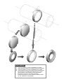
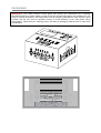
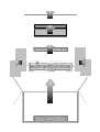
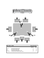
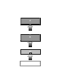
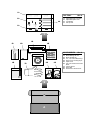
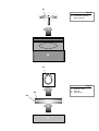
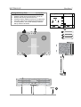
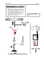
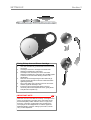
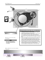
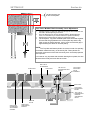
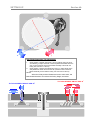
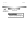
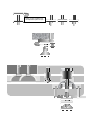
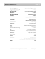
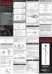
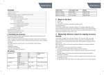
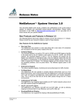
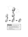
INNER PLATTER
1A
2A
3B
4B
5
6
SAW CUT FROM 6 ½ “ SOLID ALUMINUM ALLOY BAR
PRECISION MACHINED TO SHAPE (TUNED RESONANCE)
CUT FROM 16 SWG ALUMINUM ALLOY PLATE
PRECISION MACHINED TO SHAPE (TUNED RESONANCE)
PLATE PRESS FITTED ON CENTRE BOSS AND ITS
SURFACE AND EDGE PRECISION MACHINED FOR FINAL
SIZE AND ACCURACY
COMPLETE INNER PLATTER LINEARLY DAMPED FREE OF
ANY UNWANTED RESONANCE
OUTER PLATTER
1A
2A
3B
4B
5
6
SAW CUT FROM 12 “ SOLID ALUMINUM ALLOY BAR
PRECISION MACHINED TO SHAPE (TUNED RESONANCE)
SAW CUT FROM 12 “ SOLID ALUMINUM ALLOY TUBE
PRECISION MACHINED TO SHAPE (TUNED RESONANCE)
RIM HEATED TO EXPAND AND CENTRE PART FITTED
WHEN COOLED THE OUTER PLATTER PRECISION
MACHINED FOR FINAL SIZE AND ACCURACY
COMPLETE OUTER PLATTER LINEARLY DAMPED FREE
OF ANY UNWANTED RESONANCE
PACKAGING
IMPORTANT: Your TMS2 reference record player main plinths are constructed from a specially
formulated material not unlike marble or stone and hence are extremely fragile. The packaging for your
TMS2 is carefully designed for safe transportation and all packaging material/parts used must be in good
condition and the unit must be repacked correctly to avoid shattering of the main plinths during
transportation. Please study the following section and keep all packaging material intact for safe future
transportation.
1
2
3
5
5
5
6
13
7
8
4
5
10
9
12
11
1
2
RECORD PLAYER
1, 2, 3
4, 5
6, 7
8, 9, 10
11, 12, 13
Narrow Plinth Packing Cards
Wide Plinth Packing Cards
Wide Plinth Packing Cards
Square Plinth Packing Rubber Sheet
Rectangular Plinth Packing Rubber Sheet
3
Plinth Protection
Remove
Refit
1st
2nd
3rd
4th
5th
5th
4th
3rd
2nd
1st
A
1
B
2
C
3
1A
TOP TRAY
2A
4A
1A
2A
3A
4A
Box A
Adjustable feet Lock Nuts
Adjustable Spike Feet
Foot Bases
Set-up Feet
3A
1
1B
3B
2B
4B
ACCESSORIES
5B
6B
8B
7B
9B
1B
2B
3B
4B
5B
6B
7B
8B
9B
2
A
Box A
Main Bearing Oil vial
Main Spindle cap
2.5, 3.0, 5.0mm Allen Keys
Dust Cover Locating stops
Spirit Level
Lint Free Tissue and Cotton
Buds
Cotton Gloves
Drive Belt
RCA Phono Ground Link
1A
Box B
1A
Inner Platter and Main
Bearing Spindle
1
B
1A
Tray C
2A
1
3A
2
C
1A
2A
3A
ROK-DC1 Lead
Felt Matt
Outer Platter
SETTING UP
Section 1
Fitting the Set-up Feet
1
2
3
4
Top Tray Box A
Prepare a clean strong level surface to work on
Remove the Set-up Feet from the tray
Carefully rest the TMS2 on its front on a clean and
soft cloth. Support the Sub-plinth while doing this.
Locate inserts (1, 2 & 3) and carefully screw the
Set-up Feet on as shown
1
TMS2
UNDERSIDE
2
3
LEVEL
SETTING UP
Section 2
Fitting the Inner Platter
1
2
3
4
5
Box A, Box B
Pull out the Main Bearing Plug and place it in the Oil Vial
bag
Carefully clean the Main Bearing with one of the Cotton
Buds and check that there is a ball impression on the tip
Use a clean Allen key and charge the Main Bearing with
4 to 5 drops of Roksan supplied Oil
Wear the cotton gloves and remove the Inner Platter
from its bag: use the Lint Free Tissue and gently clean
the Inner Platter Spindle free from any dirt
Gently place the Inner Platter Spindle into the Main
Bearing and allow it to settle down *
5
4
3
2
2
1
*
Due to very tight tolerances the
Inner Platter will take some time to
settle down
4
SETTING UP
Section 3
Fitting Pickup Arm and Phono Cartridge
1
2
3
4
5
6
Use 3mm A/F Allen key provided and remove the Acetal
arm board
Carefully fix the Phono cartridge to the head-shell
following manufacturer’s instructions
Carefully mount the Pickup arm to the arm board
following manufacturer’s instructions (do not fully tighten
to the arm to the arm board allowing for later VTA
adjustment)
Remount arm board tightening the Allen bolts fully (if
required support the arm board from underneath while
tightening the bolts)
Plug in the pickup arm 5-pin DIN connector and check
that the top plinth assembly is free
Ensure the gap around the Sub-plinth is even (if
necessary use the Tilt Adjustment Screw, gently lift the
Sub-plinth and reposition it)
IMPORTANT NOTE
When the tone arm to be fitted is too heavy or too light for the
factory set suspension (according to the arm board cutout),
then the Mid-plinth position will move down or up by more
than 3mm. There are no adjustments from outside of the
record player for this. Only Roksan or Roksan appointed
distributor/retailer, trained on setting up the TMS 2, should
carry out this adjustment.
SETTING UP
Section 4
A
1
2
3
B
4
Fitting Drive Belt, Outer Platter & Level Adjustments
1
2
3
Marking on the Drive Belt
by Roksan
4
The arrow indicates the
out side and the direction
of rotation
5
Carefully place/fit tone arm counter weight
Carefully remove the motor transit screw (place in a bag and
store in the accessories box for future use)
Remove the Drive belt from the bag and gently place it around
the inner platter and the motor pulley (Note the TMS2 will
perform better when the belt is not inside out and when it is the
right way up. To check for this refer to the marking on the drive
belt)
Remove outer platter from bag and gently place it upside down
over the inner platter and ensure that it seats correctly on its
recess (To avoid marking/tarnishing the platter use the cotton
gloves provided. Be extra careful to ensure the platter does not
slip through your hands as this could cause some damage)
Check the alignment of the motor pulley against the inner/outer
platter by looking in the directions ‘A’ & ‘B’ (View the Top edge
and the Flange of the pulley to see if it is level with the
inner/outer platter) for this adjustment see instructions below
Motor Pulley & Inner/outer platter
alignment
View from B
View from A
SETTING UP
Section 4a
1 to 3mm clearance gap
for all 3 chrome pillars
3
Top / Sub / Middle Plinth Assembly Level Adjustment
1
2
3
4
2
Carefully insert the 2.5mm A/F Allen key through the Foot Insert and find
the TMS 2 ‘BLOB’ adjusting screw hole
Once the Allen key has correctly engaged with the ‘BLOB’ adjusting
screw, turn the Allen key to raise or lower the Top Plinth Assembly
Repeat this procedure with the other two suspension points
The Sub-plinth, Top plinth & Middle plinth raise and lower together
(Ensure that the gap between the chrome pillar top and the top
plinth recess is always between 1mm to 3mm and that this gap is
approximately the same for all three pillars)
NOTE:
The Top, Mid and Bottom plinths are custom made of a specially
formulated material and may not be exactly flat. These plinths are
structural components of the TMS 2 and only their structural properties
are important.
1
It is however very important that the Main bearing/Inner platter, the Arm
Board and the Pulley are level with each other.
MID PLINTH
SUSPENSION
SUB-PLINTH
TOP PLINTH
TOP PLINTH
SUSPENSION RING
MOUNT
TOP PLINTH
ADJUSTING
‘BOLB’
ASSEMBLY
MID PLINTH
TOP PLINTH
SUSPENSION
MOUNT
TOP PLINTH
PROGRESSIVE
DAMPING
SUSPENSION
RINGS
BOTTOM
PLINTH
SUB-PLINTH
SUSPENSION
ADJUSTMENT
WASHER
SUB-PLINTH
SUSPENSION
MOUNTS
SETTING UP
Section 4b
T
4
1
A
B
Sub-Plinth Assembly Tilt Adjustment
1
2
Gently tighten or slacken fixing bolts 1 & 4 accordingly (using the 5mm
A/F Allen key) to adjust the level of the Sub-plinth/Inner Platter about the
axis ‘A’ (Check that the Inner/Outer Platter assembly is level with the
Pulley; See view from ‘A’ above)
Gently tighten or slacken Tilt adjustment screw T to adjust the tilt of the
Sub-plinth/Inner Platter about the axis ‘B’ (Check that the Inner/Outer
Platter assembly is level with the Pulley; See view from ‘B’ above)
NOTE:
When the Pulley and the Platters are level to each other, the
Belt should ride about 1mm above the Pulley flange; see below
TILT ADJUSTMENT ABOUT AXIS ‘A’
TILT ADJUSTMENT ABOUT AXIS ‘B’
SETTING UP
Section 4c
Belt riding position
1 mm gap between the Belt and
the Pulley flange
The Belt should ride with at
lease 2mm clearance from the
bottom of the Inner Platter
(Pulley flange thickness is 1mm)
Drive Belt Set-up and Maintenance
1
If the levels are adjusted but the drive belt rides a little too high,
then remove the belt and gently stretch it. Wait a couple of
minutes and refit the drive belt and the outer platter and check the
running position again (Repeat this process if necessary)
1
Screw on the Lock Nuts over
the Adjustable Spike feet (x3)
3
1A
1
SPECIFICATIONS
TMS 2
Main Bearing Spindle
Roundness & Concentricity
Length to Diameter ratio
Super precision Tungsten Carbide
< 1 Micron
11:1
Main Bearing Ball
Roundness
Diameter
Super precision Tungsten Carbide
< 1 Micron
2mm
Main Bearing Housing
Clearance
Solid Phosphor Bronze
2/10000”
Inner Platter
2 Piece solid Al alloy
Interference fitted non-resonant
Outer Platter
2 Piece solid Al alloy
Interference fitted non-resonant
Plinth Structure
4 Plinth Design
Suspension
6 Level De-coupling
Motor
Custom made 24 pole synchronous
Pulley
Roundness & Concentricity
Belt
Motor Mount
Solid Al. Alloy
< 1 Micron
Precision ground Neoprene
Unique synchronizing bearing
Motor Drive
Super XPS.V (internal)
Wow & Flutter
<0.02
Rumble
Dimensions
<-80dB
450x370x110mm
(incl. Feet & base) 450x370x150mm
(incl. Feet & base & dust cover) 450x370x220mm
Weight
All specifications are liable to change without prior notice. E&OE
18 Kg
Printed in England