1
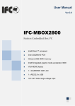
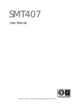
User Manual Ver 2.0 http://www.ifc-ipc.cn/ IFC-BOX4000 Fanless Embedded Box PC Intel® Haswell™ Celeron® Processor 2957U Processor Intel Haswell Core4 I3-4030U-1.9GHz CPU Intel Haswell Core4 I5-4278U-3.1GHz CPU Intel Haswell Core4 I7-4578U-3.5GHz CPU SODIMM DDR3 Socket Intel® HD Graphics Integrated Graphic Card DVI-I/HDMI/DP Display 4 x Intel®I210 GbE LAN 2 x RS-232/ Isolation RS-485, 4 x RS-232 4 x USB2.0, 2 x USB3.0 +9V~+30V Extended Voltage Input 1 IFC-BOX4000 User Manual Copyright The documentation and the software included with this product are copyrighted 2013 By IFC. All rights are reserved. IFC reserves the right to make improvements in the products described in this manual at any time without notice. No part of this manual may be reproduced/ copied/ translated or transmitted in any form or by any means without the prior written permission of IFC. Information provided in this manual is intended to be accurate and reliable. However, IFC assumes no responsibility for its use, nor for any infringements of the rights of third parties which may result from its use. Acknowledgements Award is a trademark of Award Software International, Inc.. CHRONTEL is a trademark of Chrontel Inc.. Creative is trademark of Creative Technology Ltd.. ESS is a trademark of ESS Technology, Inc.. IBM% PC/AT PS/2 & VGA is a trademark of International Business Machines Corporation. Intel®, Pentium® is a trademark of Intel Corporation. Microsoft Windows® is a trademark of Microsoft Corp.. RTL is a trademark of Realtek Semi-Conductor Co., Ltd.. SMI is a trademark of Silicon Motion, Inc.. UM is a trademark of United Microelectronics Corporation. VIA is a trademark of VIA Technologies, Inc.. All other product names or trademarks are properties of their respective owners. For more information about this and other IFC products, please visit our web site at: http://www.IFC-ipc.cn ii IFC-BOX4000 User Manual ver 2.0 Product Warranty (1 years) IFC warrants to you, the original purchaser, that each of its products will be free from defects in materials and workmanship for one years from the date of purchase. This warranty does not apply to any products which have been repaired or altered by persons other than repair personnel authorized by IFC, or which have been subject to misuse, abuse, accident or improper installation. IFC assumes no liability under the terms of this warranty as a consequence of such events. Because of IFC’s high quality-control standards and rigorous testing, most of our customers never need to use our repair service. If an IFC product is defective, it will be repaired or replaced at no charge during the warranty period. For out of warranty repairs, you will be billed according to the cost of replacement materials, service time and freight. Please consult your dealer for more details. If you think you have a defective product, follow these steps: 1. Collect all the information about the problem encountered. (For example, CPU speed, IFC products used, other hardware and software used, etc.) Note anything abnormal and list any onscreen messages you get when the problem occurs. 2. Call your dealer and describe the problem. Please have your manual, product, and any helpful information readily available. 3. If your product is diagnosed as defective, obtain an RMA (return merchandise authorization) number from your dealer. This allows us to process your return more quickly. 4. Carefully pack the defective product, a fully-completed Repair and Replacement Order Card and a photocopy proof of purchase date (such as your sales receipt) in a shippable container. A product returned without proof of the purchase date is not eligible for warranty service. Declaration of Conformity FCC Class A Note: This equipment has been tested and found to comply with the limits for a Class A digital device, pursuant to part 15 of the FCC part15, CE E50252E, GB9254 Rules. These limits are designed to provide reasonable protection against harmful interference when the equipment is operated in a commercial environment. This equipment generates, uses, and can radiate radio frequency energy and, if not installed and used in accordance with the instruction manual, may cause harmful interference to radio communications. Operation of this equipment in a residential area is likely to cause harmful interference in which case the user will be required to correct the interference at his own expense. iii IFC-BOX4000 User Manual ver 2.0 Technical Support and Assistance 1. Visit the IFC web site at www.ifc-ipc.cn where you can find the latest information about the product. 2. Contact your distributor, sales representative, or IFC's customer service center for technical support if you need additional assistance. Please have the following information ready before you call: – Product name and serial number – Description of your peripheral attachments – Description of your software (operating system, version, application software, etc.) – A complete description of the problem – The exact wording of any error messages Warnings, Cautions and Notes Warning! Warnings indicate conditions, which if not observed, can cause personal injury! Caution! Cautions are included to help you avoid damaging hardware or losing data. Note! Notes provide optional additional information. iv IFC-BOX4000 User Manual ver 2.0 Safety Instructions 1. Read these safety instructions carefully. Keep this User Manual for later reference. 2. Disconnect this equipment from any AC outlet before cleaning. Use a damp cloth. Do not use liquid or spray detergents for cleaning. 4. For plug-in equipment, the power outlet socket must be located near the equipment and must be easily accessible. 5. Keep this equipment away from humidity. 6. Put this equipment on a reliable surface during installation. Dropping it or letting it fall may cause damage. 7. The openings on the enclosure are for air convection. Protect the equipment from overheating. Do not cover the openings. 8. Make sure the voltage of the power source is correct before connecting the equipment to the power outlet. 9. Position the power cord so that people cannot step on it. Do not place anything over the power cord. 10. All cautions and warnings on the equipment should be noted. 11. If the equipment is not used for a long time, disconnect it from the power source to avoid damage by transient overvoltage. 12. Never pour any liquid into an opening. This may cause fire or electrical shock. 13. Never open the equipment. For safety reasons, the equipment should be opened only by qualified service personnel. 14. If one of the following situations arises, get the equipment checked by service personnel: The power cord or plug is damaged. Liquid has penetrated into the equipment. The equipment has been exposed to moisture. The equipment does not work well, or you cannot get it to work according to the user's manual. The equipment has been dropped and damaged. The equipment has obvious signs of breakage. 15. Do not leave this equipment in an environment where the storage temperature may go below -20° c (-4° f) or above 60° c (140° f). This could damage the equipment. The equipment should be in a controlled environment. 16. Caution: danger of explosion if battery is incorrectly replaced. Replace only with the same or equivalent type recommended by the manufacturer, discard used batteries according to the manufacturer's instructions. 17. Caution: Any unverified component could cause unexpected damage. To ensure the correct installation, please always use the components (ex. Screws) provided with the accessory box. 18. Caution: The computer is provided with a battery-powered real-time clock circuit. There is a danger of explosion if battery is incorrectly replaced. Replace only with same or equivalent type recommended by the manufacture. Discard used batteries according to the manufacturer’s instructions. v IFC-BOX4000 User Manual ver 2.0 19. Caution: Always completely disconnect the power cord from your chassis whenever you work with the hardware. Do not make connections while the power is on. Sensitive electronic components can be damaged by sudden power surges The sound pressure level at the operator's position according to IEC 704-1:1982 is no more than 70 dB (A). Disclaimer: This set of instructions is given according to IEC 704-1. IFC disclaims all responsibility for the accuracy of any statements contained herein. Packing list Before installation, please ensure the following items have been shipped: 1 x IFC-BOX4000 BOX PC AC-DC adapter, DC [email protected] 90W, with 5.08mm JACK, 0 ~ 45 ° C, a perfect solution for home and office application. Ordering Information vi Model Number Description IFC-BOX4300 Intel® Haswell™ Core® Processor i3-4030U 1.9GHz, DVI-I/DP Display , 4 pcs POE Gigabit Network , 4 pcs RS232 , 2 pcs RS232/ Isolation 485 Optional , 4USB , Direct 9-30V Input IFC-BOX4500 Intel® Haswell™ Core® Processor i5-4278U 3.5GHz, DVI-I/DP Display , 4 pcs POE Gigabit Network , 4 pcs RS232 , 2 pcs RS232/ Isolation 485 Optional , 4USB , Direct 9-30V Input IFC-BOX4700 Intel® Haswell™ Core® Processor i7-4578U-3.5GHz, DVI-I/DP Display , 4 pcs POE Gigabit Network , 4 pcs RS232 , 2 pcs RS232/ Isolation 485 Optional , 4USB , Direct 9-30V Input IFC-BOX4000 User Manual ver 2.0 Contents GENERAL INTRODUCTION................................................................................................................. 1 1.1 INTRODUCTION......................................................................................................................... 2 1.2 FEATURES ............................................................................................................................... 2 1.3 SPECIFICATIONS ...................................................................................................................... 2 1.4 OS SUPPORT .......................................................................................................................... 4 1.5 OTHER .................................................................................................................................... 4 1.6 ENVIRONMENTAL SPECIFICATIONS ............................................................................................. 4 1.7 MECHANICAL SPECIFICATIONS ................................................................................................... 5 H/W INSTALLATION ............................................................................................................................ 7 2.1 JUMPERS ................................................................................................................................ 8 2.2 EXTERNAL I/O CONNECTORS & PIN ASSIGNMENTS .................................................................... 12 BIOS SETTINGS ................................................................................................................................ 17 3.1 BIOS OVERVIEW ................................................................................................................... 18 3.2 MAIN MENU ........................................................................................................................... 19 3.3 ADVANCED MENU ................................................................................................................... 20 3.4 CHIPSET................................................................................................................................ 27 3.5 BOOT MENU .......................................................................................................................... 32 3.6 SECURITY MENU .................................................................................................................... 33 3.7 SAVE CHANGES AND EXIT ....................................................................................................... 34 S/W INTRODUCTION & INSTALLATION ........................................................................................... 35 4.1 S/W SERVICE INTRODUCTION .................................................................................................. 36 4.2 W ATCHDOG PROGRAM EXAMPLE .............................................................................................. 36 4.3 GPIO PROGRAM EXAMPLE ...................................................................................................... 36 INDEX: A ............................................................................................................................................ 37 vii А.1 SYSTEM I/O PORTS ................................................................................................................ 38 А.2 1ST MB MEMORY MAP ........................................................................................................... 38 А.3 DMA CHANNEL ASSIGNMENTS ................................................................................................ 39 А.4 INTERRUPT ASSIGNMENTS....................................................................................................... 39 IFC-BOX4000 User Manual ver 2.0 Chapter 1 General Introduction This chapter gives background information on IFC-BOX4000 series. 1 IFC-BOX4000 User Manual 1.1 Introduction The fanless embedded computer IFC-BOX4000 is an ideal solution for ready-to-use system applications. All electronics are protected in a compact, sealed aluminum case. It offers anti-vibration and dustproof as well as passive cooling solution making it a convenient & flexible solution for customers embedding in their own cabinet, or to use it as a stand-alone system, thereby meeting the requirements of limited space and harsh environment. IFC-BOX4000 is designed as a palm-size fanless embedded system and occupies only 260 x 176 x 49 mm 260 x 176, The rugged, cast aluminum case not only provides great protection from EMI, shock/vibration, cold and heat, but also provides passive cooling for quiet, fanless operation. IFC-BOX4000 supports DVI-I+DP three synch. Or asynch. display, 4 x GbE LAN, 2 x USB 2.0, 2 x USB 3.0 and 4 x RS-232, 2 x RS-485, 2.5" SATA HDD, m-SATA SSD, DC +7V~30V extended power supply. 1.2 Features Key features Extremely compact, sealed architecture, fanless design and low power consumption system Support Intel® Haswell™ Celeron® Processor 2957U 1.4GHz Dual core CPU Intel Haswell Core4 I3-4030U-1.9GHz CPU Intel Haswell Core4 I5-4278U-3.1GHz CPU Intel Haswell Core4 I7-4578U-3.5GHz CPU Ultra-slim handheld system, support 2.5" SATA HDD/M-SATA SSD DVI-I/DP dual synch. & asynch. display, support 4K resolution 4 x GbE LAN, 2x USB 2.0, 2x USB 3.0, 4 x RS-232, 2 x RS-232 / lsolation RS-485 Support VESA/ Desktop installation 1.3 Specifications 1.3.1 General CPU: Intel® Haswell™ Celeron® Processor 2957U 1.4GHz Dual Core CPU, Intel Haswell Core4 I3-4030U-1.9GHz CPU Intel Haswell Core4 I5-4278U-3.1GHz CPU Intel Haswell Core4 I7-4578U-3.5GHz CPU System Chipset: Intel® Haswell™ SOC chipset BIOS: AMI 16 Mbit Flash BIOS 2 IFC-BOX4000 User Manual ver 2.0 System Memory: SODIMM socket, DDR3L-1333/1600 ; LPDDR3-1333/1600, Support Max. 16GB Watchdog Timer: 255-level interval timer, setup by software Serial Ports: 2 x RS232/RS485 jumper setting, RS485 supports software flow control; 4 x RS232 , Support 3000V Surge protection; USB: 2 x USB 2.0 2 x USB 3.0 Audio: High definition auto encoding - Realtek ALC6622 audio card, with MIC/audio output Expansion Bus: Support 1 x full-size Mini-PCIe, 3G UIM card, 1 x Half lengthsize Mini-PCIe Storage: Support Msata SSD or 1* 2.5"SATAIII HDD ( 9.5 mm ) 1.3.2 Display Chipset: Intel® HD Graphics,200-1GHz frequency DVI-I/DP dual synch. & asynch. Display Resolution: support Max. 4K resolution 1.3.3 Ethernet Chipset: Intel® I210 GbE LAN Speed: 10/100/1000 Mbps, suppot Wake-on-Lan Connector: 4 x RJ45 Standard: Compliant with IEEE 802.3, IEEE 802.3u, IEEE 802.3x, IEEE 8023y, IEEE 802.ab. 1.3.4 Electrical Specifications Power Input: DC +9V ~ +30 V Power On Type: AT / ATX Jumper selection APM: ACPI 3.0, APM Power Adapter: AC ~ DC 12V/3A , 36W Power consumption: 2957U-1.4GHz (Fanless) Voltage Current Power 0.5 6 Idle mode +12V 3 IFC-BOX4000 User Manual ver 2.0 Power on +12V 1.1 13.2 Max load +12V 1.7 20.4 Power consumption test conditions: Test Condition: Windows 7 professional Professional, Burntest ver5.3, 32G SSD Idel Mode: The power consumption without running any application software after entering to Windows system. Boot Mode: The max. Power consumption between power-on and entering to system process. Full-load Mode: The power consumption under 100% full-load operation of CPU and graphic card when running Burntest. RTC battery: Lithium 3 .3V/210mAH CR2032 battery 1.4 OS Support It supports Support Win7, Win8, Win CE 6.0, and Linux Ubuntu 10.04 UP. 1.5 Other Power switch, power indicator 1 -255 sec. watchdog 12 bits, support routine, self-define I/O, 3.3V@24mA IFC-BOX4000 User Manual 1.6 Environmental Specifications Operating temperature: -20 ~ 60° C (extended temp. SSD/mSATA device) 0 ~ 40° C (HDD) Relative humidity: 95% @ 40°C (non-condensing) Storage temperature: -40 ~ 85°C (-40 ~ 185°F) Vibration loading during operation: – With SSD: 3 Grms, IEC 60068-2-64, random, 5 ~ 500 Hz, 1 hr/axis Shock during operation: – With SSD: 30 G, IEC 60068-2-64, half sine, 11 ms duration time. Safety: In compliance with UL,CCC EMC: CE, FCC A, ROSH certificate 4 IFC-BOX4000 User Manual ver 2.0 1.7 Mechanical Specifications 5 IFC-BOX4000 User Manual ver 2.0 Figure 1.7 IFC-BOX4000 mechanical dimension drawing 6 IFC-BOX4000 User Manual ver 2.0 Chapter 2 H/W Installation This chapter explains the setup procedures of the IFC-BOX4000 hardware, including instructions on setting jumpers and connecting peripherals, switches and indicators. Be sure to read all safety precautions before you begin the installation procedure. 7 IFC-BOX4000 User Manual ver 2.0 2.1 Jumpers 2.1.1 Jumper Description Board can be configured by setting jumpers. A jumper is a metal bridge used to close an electric circuit. It consists of two metal pins and a small metal clip (often protected by a plastic cover) that slides over the pins to connect them. To close a jumper, you connect the pins with the clip. To open a jumper, you remove the clip. Sometimes a jumper will have three pins, labeled 1, 2 and 3. In this case you would connect either pins 1 and 2, or 2 and 3. The jumper settings are schematically depicted in this manual as follows. A pair of needle-nose pliers may be helpful when working with jumpers. If you have any doubts about the best hardware configuration for your application, contact your local distributor or sales representative before you make any changes. Generally, you simply need a standard cable to make most connections. Warning! To avoid damaging the computer, always turn off the power supply before setting jumpers. How to verify Pin1 of the jumper? 1. Please check the M/B carefully, where there is a mark of “1” or white thick line, there is Pin1. 2. Look into the pad on the back side of the M/B, generally the square side of the pad is Pin1. 8 IFC-BOX4000 User Manual ver 2.0 2.1.2 IFC-BOX4000 Installation Unscrew pan head fixed chassis around 8 M2.5, remove the lower cover of the computer case can be carried out from the bottom, hard disk, M-SATA, memory, Mini-PCIe equipment installation. And can be set up to the corresponding functional jumper 9 IFC-BOX4000 User Manual ver 2.0 2.1.3 Jumper Setting JCMOS CMOS Clear/AT & ATX Power Mode Select Part Number Description 10 Pin Header 1x3Pin 2.54mm DIP & Jumper 2.54mm Setting Function 1-2 On (Default) Normal 2-3 On Clear BIOS IFC-BOX4000 User Manual ver 2.0 2.1.4 IFC-BOX4000 I/O Indication Figure 2.1.4 IFC-BOX4000 mechanical dimension drawing 11 IFC-BOX4000 User Manual ver 2.0 2.2 External I/O Connectors & Pin Assignments JCOM1 Part Number Description CONN (Green end) 2x6P 3.81mm Male 90°DIP-18 Pin Signal Pin Signal 1 12V@2A Output 2 A- ( COM5-RS485 ) 3 G 4 A+ ( COM5-RS485 ) 5 5V@2A Output 6 SG 7 G 8 B- ( COM6-RS485 ) 9 PB (Power switch signal) 10 B+ ( COM6-RS485 ) 11 G 12 SG ( RS485 GND Signal ) Support a maximum rate of 115200bps, RS485 RS485 supports 3000KV isolation, automatic flow, flow control. This interface also supports the connection of external switch, +12V/5V power output is connected to the supply of external equipment. COM1 Part Number Description COM Port D-Sub 9Pin Male DIP Pin Signal Pin RX3 1 2 3 TX2 4 5 GND 6 7 RX4 8 9 GND 9 Wire RS232 Interface , Support a maximum protection. COM2-COM4 Part Number 12 IFC-BOX4000 User Manual ver 2.0 Signal RX2 GND TX3 TX4 115200bps Rate , Support 4000V Surge Description COM Port D-Sub 9Pin Male DIP Pin Signal Pin Signal RX3 1 2 RX2 3 TX2 4 GND 5 GND 6 TX3 7 RX4 8 TX4 9 GND Provide 3 and 3 wire RS-232 serial communication port, support a maximum rate of 115200bps, 4000V surge protection. GPIO Part Number Description Pin 1 3 5 7 9 11 13 15 GPIO CONN D-SUB 15Pin VGA DIP-15 Signal Pin Signal GPIO1 GPIO3 GPIO5 GPIO7 GPIO9 GPIO11 GND V3.3S 2 4 6 8 10 12 14 GPIO2 GPIO4 GPIO6 GPIO8 GPIO10 GPIO12 GND Free programming is defined as the input or output, the driving power of 3.3V@24mA DVI Port Part Number Description Pin 1 3 13 DVI-D 24Pin Fe male DIP Signal Pin Signal TX2SHLD24 2 4 TX2+ TX4- IFC-BOX4000 User Manual ver 2.0 TX4+ 6 DDCC 5 DDCD 8 VSYNC 7 TX110 TX1+ 9 SHLD13 12 TX311 TX3+ 14 VDDC 13 GND 16 HPD 15 HPD 18 TX0+ 17 SHLD05 20 TX519 TX5+ 22 SHLDC 21 TXC+ 24 TXC23 DVI-I connector, do not support the VGA signal, you can use the DVI-D switching VGA converter with a VGA monitor, support 4096X2304@24HZ high resolution DP Display Port Part Number Description Pin 1 3 5 7 9 11 13 15 17 19 DP 20Pin Fe male DIP Signal Pin Signal LANE_0P LANE_0N GND 7 LANE_2P LANE_2N GND MODE AUXP AUXN PWR_RET 2 4 6 8 10 12 14 16 18 20 GND LANE_1P 6 LANE_1N GND LANE_3P LANE_3N CEC GND HPD PWR DP support max. resolution 3200X2000@60HZ, support DP Dangle device. Power Input Connector (DC_IN1) Part Number Description DC-Jack 3Pin DIP 14 IFC-BOX4000 User Manual ver 2.0 Pin Signal Pin Signal 1 DC 2 DC 3 GND IFC-BOX4000 with a 9-30V support DC external power input of the phoenix head jack. The ACC signal is connected with a vehicle ACC signal support. Power ON/OFF Button (PWR_SW1) Part Number Description Power Button LED PTCT-07-A 5P 7Pin DIP IFC-BOX4000 has a power button with LED indicator. USB1 Part Number Description Pin 1 3 5 7 9 S1 S3 1. 2. Double USB Port AF90° 12Pin DIP Signal VBUS D+ SSRXDRAIN SSTX+ GND GND Pin 2 4 6 8 Signal DGND SSRX+ SSTX- S2 S4 GND GND 2 x USB, all support PNP & hot-plug functions. USB ports are in compliance with USB UHCI, Rev. 3.0 standard. It can connect max. 127 external devices. USB port provides max. 1A current load capacity. USB2 Part Number Description 15 USB3.0 USB2.0 IFC-BOX4000 User Manual ver 2.0 Double USB Port AF90° 12Pin DIP Pin Signal Pin Signal 1 USB_VCC 2 USB_PORT2# 3 USB_PORT2 4 GND 5 USB_VCC 6 USB_PORT3# 7 USB_PORT3 8 GND 9 CHASSIS_USB 10 CHASSIS_USB 11 CHASSIS_USB 12 CHASSIS_USB 1. The 1 provides 2 USB interface, support plug and play and the hot swap function, can be up to 127 external connection equipment. USB interface with USB UHCI, the Rev. 2 standard. The USB interface supports plug and play function, allows to connect or disconnect the device of the user at any time, without having to shut down the computer. 2. USB ports to provide maximum 1A current load capacity. Ethernet Part Number Description RJ45 Port 8PIN DIP 1 8 Pin Signal Pin Signal Transmit Data+ Transmit Data1 2 Receive Data+ Bi-directional Data+ 3 4 Bi-directional DataReceive Data5 6 Bi-directional Data+ Bi-directional Data7 8 IFC-BOX4000 provides 4 POE RJ45 LAN port, in full compliance with the IEEE 802.3u 10/100/1000 Base-T CSMA/CD standard. RJ-45 connector using standard Ethernet port, support 48V@500mA POE power output, Link/Speed LED lights, for indicating transmission / connection state and speed condition. AUDIO Part Number Description AUDIO Jack Green Vertical 5Pin DIP Pin Signal Pin Signal Provide two 3.5 stereo audio input & output. Audio chip controller is ALC662, in compliance with Azalea standard. 16 IFC-BOX4000 User Manual ver 2.0 Chapter 3 BIOS Settings 17 IFC-BOX4000 User Manual ver 2.0 3.1 BIOS Overview BIOS (Basic Input and Output System) is solidified in the flash memory on the motherboard. Main functions including: initialize system hardware, set operating status of the system components, adjust operating parameters of the system components, diagnose the functions of the system components and report failures, provide hardware operating and controlling interface for the upper level software system, guide operating system etc.. BIOS provides users with a parameters for users, control power management mode and adjust the resource distribution of system device. Enter BIOS Setup After powering on the system, press <Del> or <ESC> to enter BIOS setup when see post logo or post message The available keys for the Menu screen are Select Menu: < ←> or < →> Select Item: < ↑> or < ↓> Select Field: <Tab> Change Fielsssd: <+> or <-> Help: <F1> Load Defaults <F3> Save & Exit: <F4> Exits the Menu: <Esc> NOTE! BOIS setting will affect computer performance directly. Improper parameter setting would cause damage to the computer; it may even unable to power on. Please use internal default value of BIOS to restore the system. Our company is constantly updating BIOS, so the setup interface may varies sometimes. The default options bellow are just for reference only. 18 IFC-BOX4000 User Manual ver 2.0 3.2 Main Menu BIOS Information (read only): To display BIOS info, including Project Name, Build Date ect. Processor Information: To display the basic Processor Information Total Memory: To display the Total Memory Memory Frequency: To display the Frequency Memory is running 19 IFC-BOX4000 User Manual ver 2.0 3.3 Advanced Menu ACPI Settings. CPU Configuration. SATA Configuration. USB Configuration. Super IO Configuration. H/W Monitor. 20 IFC-BOX4000 User Manual ver 2.0 3.3.1 ACPI Settings Enable Hibernation: Enables or Disables System ability to Hibernate (OS/S4 Sleep State). This option may be not effective with some OS.. ACPI Sleep State: Select the ACPI state used for system suspend.(S3 state). 3.3.2 CPU Configuration 21 IFC-BOX4000 User Manual ver 2.0 Show the detail information of the processor and setting for it. 22 IFC-BOX4000 User Manual ver 2.0 3.3.3 SATA Configuration SATA Controller(s): Enable or disable SATA Device. SATA Mode Selection: Determines how SATA controller(s) operate. SATA Controller Speed: Indicates the maximum speed the SATA controller can support. Serial ATA Port X(0-3): Show the sata device information detected on this port Port X(0-3) : Enable or Disable this sata port 23 IFC-BOX4000 User Manual ver 2.0 3.3.4 USB Configuration Legacy USB support: 1. Enables support for legacy USB keyboard. 2. Auto option disables legacy support if no USB devices are connected. 3. DISABLE option will keep USB devices available only for EFI applications. USB3.0 Support: Enable/Disable USB3.0 (XHCI) Controller support. XHCI Hand-off: 1. This is a workaround for OSes without XHCI hand-off support. 2. The XHCI ownership change should be claimed by XHCI driver. EHCI Hand-off: 1. This is a workaround for OSes without EHCI hand-off support. 2. The EHCI ownership change should claim by EHCI driver. USB Mass Storage Driver Support: Enable/Disable USB Mass Storage Driver Support. USB transfer time-out: The time-out value for Control, Bulk, and Interrupt transfers. Device reset time-out :USB mass storage device Start Unit command time-out. Device power-up delay: Maximum time the device will take before it properly reports itself to the Host Controller. 24 IFC-BOX4000 User Manual ver 2.0 3.3.5 Super IO Configuration Super IO Chip: Read only, to display Super IO chipset model. Serial Port 1-6 Configuration: 6 COM setup, including interruption and default address. Restore AC Power Loss: Specify what state to go to when power is re-applied after a power failure (G3 state).. 1. Power on: System will always power on when restore AC power 2. Power Off: System will not power on when restore AC power 3. Last State: whether power on depend on the state when Power Loss 25 IFC-BOX4000 User Manual ver 2.0 3.3.6 H/W Monitor PC Health Status: read only, including CPU/System temperature, Fan Speed, VCORE, VDIMM, +3.3V, +5V, +12V, VBAT. 26 IFC-BOX4000 User Manual ver 2.0 3.4 Chipset PCH-IO Configuration: PCH Parameters System Agent (SA) Configuration: System Agent (SA) Parameters 27 IFC-BOX4000 User Manual ver 2.0 3.4.1 PCH-IO Configuration PCI Express configuration: PCI Express Root Port 1-6 Setting 28 IFC-BOX4000 User Manual ver 2.0 29 IFC-BOX4000 User Manual ver 2.0 3.4.2 System Agent (SA) Configuration Graphics Configuration : Graphics Device Settings. 30 IFC-BOX4000 User Manual ver 2.0 Graphics Turbo IMON Current: Graphics turbo IMON current values supported (14-31) GTT Size: Select the GTT Size that is pre-allocated to support the Internal Graphics Translation Table. Aperture Size: Select the size of Internal graphics translation window(GMADR), which is used to access graphics memory allocated using the graphics translation table. DVMT Pre-Allocated: Select DVMT 5.0 Pre-Allocated (Fixed) Graphics Memory size used by the Internal Graphics Device. DVMT Total Gfx Mem: Select DVMT5.0 Total Graphic Memory size used by the Internal Graphics Device. 31 IFC-BOX4000 User Manual ver 2.0 3.5 Boot Menu 3.5.1 Boot Configuration Setup Prompt Timeout: Setup prompt timeout, to display waiting time. Boot up Num lock State: Select Power-on state for num lock, ON/OFF; Quiet Boot: Configure whether to display the content of customized Logo. 1. Disabled: Displays normal POST messages; 2. Enabled: Displays OEM Logo (no POST messages); Launch PXE OpROM policy: Enable or Disable Lan PXE Boot Function; 3.5.2 Boot Configuration Configure the preference of the start-up sequence for devices when the system starts up. Note: When pressing <F7> while booting it is possible manually to select boot device. 1. 2. 3. 32 Boot Option #1: Setting first boot device. Boot Option #2: Setting second boot device. Hard Drive BBS Priorities: Setting the boot priority of Hard Disk IFC-BOX4000 User Manual ver 2.0 3.6 Security Menu Change Administrator / User Password: 33 IFC-BOX4000 User Manual ver 2.0 3.7 Save Changes and Exit Save Changes and Exit This item allows you to exit system setup after saving the changes. Discard Changes and Exit This item allows you to exit system setup without saving any changes. Save Changes and Reset This item allows you to reset the system after saving the changes. Discard Changes and Reset This item allows you to rest system setup without saving any changes. Save Changes This item allows you to save changes done so far to any of the options. Discard Changes This item allows you to discard changes done so far to any of the options. Restore Defaults This item allows you to restore/load default values for all the options. Save as User Defaults This item allows you to save the changes done so far as user defaults. Restore User Defaults This item allows you to restore the user defaults to all the options. Boot Override 34 IFC-BOX4000 User Manual ver 2.0 Chapter 4 S/W Introduction & Installation 35 IFC-BOX4000 User Manual ver 2.0 4.1 S/W Service Introduction ICS provides software services as bellow: 4.2 Watchdog program example A watchdog timer (abbreviated as WDT) is a hardware device which triggers an action, e.g. rebooting the system, if the system does not reset the timer within a specific period of time. The WDT program example provides developers with functions such as starting the timer, resetting the timer, and setting the timeout value if the hardware requires customized timeout values. Please contact our service personnel for program example source code and packaging EXE executable file. 4.2.1 WDT Programming Model You can use the tool WDT.exe under DOS to test the watchdog function. Usage: WDT -? : Show help screen WDT -S Value: Set Watchdog as seconds mode, and Value is the time WDT -M Value: Set Watchdog as minutes mode, and Value is the time Example: WDT -S 5 : Set Watchdog as 5 seconds WDT -M 2 : Set Watchdog as 2 minutes 4.3 GPIO program example A GPIO is a pin that can be used as input or output, when used as output, you can set it output as low or high. Please contact our service personnel for program example source code and packaging EXE executable file. You can use the tool GPIO.exe under DOS to test whether the pin can be used as a GPIO. Usage: GPIO -? : Show help screen GPIO -I Gpio Num : Set GPIO Port as input GPIO -OH Gpio Num : Set GPIO Port output high GPIO -OL Gpio Num : Set GPIO Port output Low Example: GPIO -I 1 : Set GPIO 1 as input GPIO -OH 1 : Set GPIO 1 output high GPIO -OL 1 : Set GPIO 1 output Low 36 IFC-BOX4000 User Manual ver 2.0 Chapter 5 Index: A 37 IFC-BOX4000 User Manual ver 2.0 А.1 System I/O Ports Addr. Range 000-01F DMA 020-021 Interrupt 040-043 Timer/Counter 060-06F 8042 070-07F Real-time 080-09F DMA 0A0-0BF Interrupt 0C0-0DF DMA 274-279 ISAPNP read data port 2F8-2FF COM2 3B0-3DF VgaSave 3F8-3FF COM1 400-4D1 Interrupt 500-77F Motherboard A79-A79 ISAPNP read data port B78-B7F Motherboard Table 5.1: System I/O Ports А.2 1st MB Memory Map Addr. Range (Hex) Device 00000000h - 00003FFFh 000A0000h - FEBFFFFFh Motherboard resources PCI bus FEC00000h - FEC00FFFh Motherboard resources FED00000h - FED003FFh High precision event timer FED14000h - FED19FFFh System board FED1C000h - FEE00FFFh Motherboard resources FF000000h - FFFFFFFFh Intel 82802 firmware Hub Device Table 5.2: 1st MB Memory Map 38 IFC-BOX4000 User Manual ver 2.0 А.3 DMA Channel Assignments Channel Function 0 1 Available Available 2 Available 3 Available 4 Direct memory access controller 5 Available 6 Available 7 Available Table 5.3: DMA Channel Assignments А.4 Interrupt Assignments Interrupt# Interrupt source IRQ0 IRQ1 IRQ3 System timer Standard 101/102-Key or Microsoft Natural PS/2 Keyboard COM2 IRQ4 COM1 IRQ8 System CMOS/real time clock IRQ9 Microsoft ACPI-Compliant System IRQ11 SMBUS Controller IRQ16 Network /USB IRQ17 Network IRQ18 USB IRQ19 SATA IRQ22 HDA IRQ23 USB Table 5.4: Interrupt Assignments 39 IFC-BOX4000 User Manual ver 2.0 Made in China www.IFC-ipc.cn 40 IFC-BOX4000 User Manual ver 2.0