1
FT9Y-B1386(2)
FBD Programming Manual
SAFETY PRECAUTIONS
Read the SmartAXIS Pro/Lite User’s Manual and SmartAXIS Touch User's Manual to make sure of correct operation before starting installation,
wiring, operation, maintenance, and inspection of the SmartAXIS.
All SmartAXIS modules are manufactured under IDEC’s rigorous quality control system, but users must add a backup or failsafe provision to the
control system when using the SmartAXIS in applications where heavy damage or personal injury may be caused in case the SmartAXIS should
fail.
In this user’s manual, safety precautions are categorized in order of importance to Warning and Caution:
Warning
Warning notices are used to emphasize that improper operation may cause severe personal injury or death.
The SmartAXIS is not designed for use in medical equipment, nuclear power, railways, aviation, passenger vehicle equipment, or similar
applications requiring a high degree of reliability and safety. The SmartAXIS cannot be used for such applications.
When using the SmartAXIS in applications not described above that require a high degree of reliability in terms of functionality and precision,
appropriate measures such as failsafe mechanisms and redundant mechanisms must be taken for a system containing the SmartAXIS.
Emergency stop and interlocking circuits must be configured outside the SmartAXIS.
If relays or transistors in the SmartAXIS output circuits should fail, outputs may remain in the on or off state. For output signals which may
cause serious accidents, configure monitor circuits outside the SmartAXIS.
The SmartAXIS self-diagnostic function may detect internal circuit or program errors, stop programs, and turn outputs off. Configure circuits so
that the system containing the SmartAXIS is not jeopardized when outputs turn off.
Turn off power to the SmartAXIS before installation, removal, wiring, maintenance, and inspection of the SmartAXIS. Failure to turn power off
may cause electrical shocks or fire hazard.
Special expertise is required to install, wire, program, and operate the SmartAXIS. People without such expertise must not use the SmartAXIS.
Install the SmartAXIS according to the instructions described in SmartAXIS Pro/Lite User's Manual and SmartAXIS Touch User's Manual.
Improper installation will result in falling, failure, or malfunction of the SmartAXIS.
Caution
Caution notices are used where inattention might cause personal injury or damage to equipment.
The SmartAXIS is designed for installation in a cabinet. Do not install the SmartAXIS outside a cabinet.
Install the SmartAXIS in environments described in SmartAXIS Pro/Lite User's Manual and SmartAXIS Touch User's Manual. If the SmartAXIS is
used in places where the SmartAXIS is subjected to high-temperature, high-humidity, condensation, corrosive gases, excessive vibrations, and
excessive shocks, then electrical shocks, fire hazard, or malfunction will result.
The environment for using the SmartAXIS is “Pollution degree 2.” Use the SmartAXIS in environments of pollution degree 2 (according to IEC
60664-1).
While moving or transporting prevent the SmartAXIS from falling, otherwise damage or malfunction of the SmartAXIS will result.
Wiring must use lead sizes that are appropriate for the applied voltage and current. Terminal screws must be tightened with the prescribed
tightening torque.
Prevent metal fragments and pieces of wire from dropping inside the SmartAXIS housing. Put a cover on the SmartAXIS modules during
installation and wiring. Ingress of such fragments and chips may cause fire hazard, damage, or malfunction.
Use a power supply of the rated value. Use of the wrong power supply may cause fire hazard.
Use an IEC 60127-approved fuse on the power line outside the SmartAXIS. This is required when equipment containing the SmartAXIS is
designed for use in Europe.
Use an IEC 60127-approved fuse on the output circuit. This is required when equipment containing the SmartAXIS is designed for use in Europe.
Use an EU-approved circuit breaker. This is required when equipment containing the SmartAXIS is destined for Europe.
Make sure of safety before starting and stopping the SmartAXIS or when operating the SmartAXIS to force outputs on or off. Incorrect operation
of the SmartAXIS may cause machine damage or accidents.
Do not connect the ground wire directly to the SmartAXIS. Connect a protective ground to the cabinet containing the SmartAXIS using an M4 or
larger screw. This is required when equipment containing the SmartAXIS is designed for use in Europe.
Do not disassemble, repair, or modify the SmartAXIS modules.
The SmartAXIS contains electronic parts and batteries. When disposing of the SmartAXIS, do so in accordance
with national and local regulations.
SMARTAXIS FBD PROGRAMMING MANUAL FT9Y-B1386
Preface-1
ABOUT THIS MANUAL
This user’s manual describes functions, specifications, installation, and operation basics of the SmartAXIS. Also included is
information on the powerful communications tools of the SmartAXIS, as well as troubleshooting procedures.
Publication history
August 2013
October 2013
August 2014
First Edition
Second Edition
Third Edition
Caution
The contents of this manual and the SmartAXIS and WindLDR applications are copyright, and all rights are reserved by IDEC
Corporation. Unauthorized duplication, reproduction, sales, transfers, or leasing is prohibited.
The contents of this manual and the SmartAXIS and WindLDR applications are subject to change without notice.
Please contact your vendor or IDEC Corporation with any problems regarding the operation of this product.
Trademarks
SmartAXIS is a trademark of IDEC Corporation.
IMPORTANT INFORMATION
Under no circumstances shall IDEC Corporation be held liable or responsible for indirect or consequential damages resulting from
the use of or the application of IDEC PLC components, individually or in combination with other equipment.
All persons using these components must be willing to accept responsibility for choosing the correct component to suit their
application and for choosing an application appropriate for the component, individually or in combination with other equipment.
All diagrams and examples in this manual are for illustrative purposes only. In no way does including these diagrams and
examples in this manual constitute a guarantee as to their suitability for any specific application. To test and approve all
programs, prior to installation, is the responsibility of the end user.
Preface-2
SMARTAXIS FBD PROGRAMMING MANUAL FT9Y-B1386
RELATED MANUALS
The following manuals related to the SmartAXIS are available. Refer to them in conjunction with this manual.
Type No.
Manual Name
Description
FT9Y-B1378
SmartAXIS Pro/Lite
User’s Manual
Describes product specifications, installation and wiring instructions, instructions for
basic programming operations and special functions, device and instruction lists,
communication functions, and troubleshooting procedures for the SmartAXIS Pro/
Lite series.
FT9Y-B1382
SmartAXIS
Ladder Programming Manual
Describes basic operations for ladder programming, instructions for editing and
monitoring ladders on the SmartAXIS, available devices and instruction lists, and
details of each instruction.
FT9Y-B1386
SmartAXIS
FBD Programming Manual
(this manual)
Describes basic operations for function block programming, available devices and
function block lists, and details of each function block.
FT9Y-B1390
SmartAXIS Touch
User’s Manual
Describes product specifications, installation and wiring instructions, instructions for
setting basic programming actions and special functions, device and instruction lists,
communication functions, and troubleshooting procedures for the Touch series.
WindLDR Help
Describes usage instructions for WindLDR, programming software for the SmartAXIS
Pro/Lite series.
WindO/I-NV3 Help
Describes programming for the SmartAXIS Touch series, and usage instructions for
the WindO/I-NV3 configuration software.
SMARTAXIS FBD PROGRAMMING MANUAL FT9Y-B1386
Preface-3
NAMES AND ABBREVIATIONS USED IN THIS MANUAL
Model Names
Name Used in this Manual
Description (Detailed Type No.)
SmartAXIS
FT1A programmable logic controllers.
SmartAXIS Lite
Modules without LCD.
(FT1A-B12RA, FT1A-B12RC, FT1A-B24RA, FT1A-B24RC, FT1A-B40RKA, FT1A-B40RSA, FT1A-B40RC,
FT1A-B48KA, FT1A-B48SA, FT1A-B48KC, FT1A-B48SC)
SmartAXIS Pro
Modules with LCD.
(FT1A-H12RA, FT1A-H12RC, FT1A-H24RA, FT1A-H24RC, FT1A-H40RKA, FT1A-H40RSA, FT1A-H40RC,
FT1A-H48KA, FT1A-H48SA, FT1A-H48KC, FT1A-H48SC)
SmartAXIS Touch
Modules that extend the functionality of display.
(FT1A-M12RA-W, FT1A-M12RA-B, FT1A-M12RA-S, FT1A-C12RA-W, FT1A-C12RA-B, FT1A-C12RA-S,
FT1A-M14KA-W, FT1A-M14KA-B, FT1A-M14KA-S, FT1A-C14KA-W, FT1A-C14KA-B, FT1A-C14KA-S,
FT1A-M14SA-W, FT1A-M14SA-B, FT1A-M14SA-S, FT1A-C14SA-W, FT1A-C14SA-B, FT1A-C14SA-S)
12-I/O type
SmartAXIS Pro and Lite models with 12 I/O points.
(FT1A-B12RA, FT1A-B12RC, FT1A-H12RA, FT1A-H12RC)
24-I/O type
SmartAXIS Pro and Lite models with 24 I/O points.
(FT1A-B24RA, FT1A-B24RC, FT1A-H24RA, FT1A-H24RC)
40-I/O type
SmartAXIS Pro and Lite models with 40 I/O points.
(FT1A-B40RKA, FT1A-B40RSA, FT1A-B40RC, FT1A-H40RKA, FT1A-H40RSA, FT1A-H40RC)
48-I/O type
SmartAXIS Pro and Lite models with 48 I/O points.
(FT1A-B48KA, FT1A-B48SA, FT1A-B48KC, FT1A-B48SC, FT1A-H48KA, FT1A-H48SA, FT1A-H48KC,
FT1A-H48SC)
AC power type
SmartAXIS Pro and Lite models with an AC power supply.
(FT1A-B12RC, FT1A-H12RC, FT1A-B24RC, FT1A-H24RC, FT1A-B40RC, FT1A-H40RC, FT1A-B48KC,
FT1A-B48SC, FT1A-H48KC, FT1A-H48SC)
DC power type
SmartAXIS Pro and Lite models with a DC power supply.
(FT1A-B12RA, FT1A-H12RA, FT1A-B24RA, FT1A-H24RA, FT1A-B40RKA, FT1A-H40RKA,
FT1A-B40RSA, FT1A-H40RSA, FT1A-B48KA, FT1A-B48SA, FT1A-H48KA, FT1A-H48SA)
Touch (Relay output type)
SmartAXIS Touch with relay output.
(FT1A-M12RA-W, FT1A-M12RA-B, FT1A-M12RA-S, FT1A-C12RA-W, FT1A-C12RA-B, FT1A-C12RA-S)
Touch (Transistor output type)
SmartAXIS Touch with transistor output.
(FT1A-M14KA-W, FT1A-M14KA-B, FT1A-M14KA-S, FT1A-C14KA-W, FT1A-C14KA-B, FT1A-C14KA-S,
FT1A-M14SA-W, FT1A-M14SA-B, FT1A-M14SA-S, FT1A-C14SA-W, FT1A-C14SA-B, FT1A-C14SA-S)
Abbreviations
Abbreviation
Meaning
FB
Function block
For example, the AND (logical AND) function block is described as AND FB.
FBD
Function block diagram
Preface-4
SMARTAXIS FBD PROGRAMMING MANUAL FT9Y-B1386
TABLE OF CONTENTS
Safety Precautions.............................................................................................................................
About This Manual.............................................................................................................................
Related Manuals................................................................................................................................
Names and Abbreviations Used in this Manual .....................................................................................
CHAPTER 1:
Preface-1
Preface-2
Preface-3
Preface-4
Operation Basics
Starting WindLDR and PLC Selection ............................................................................................................. 1-1
Creating FBD Program ................................................................................................................................. 1-3
Convert Program ......................................................................................................................................... 1-9
Saving a Project ........................................................................................................................................ 1-10
Simulation ................................................................................................................................................ 1-11
Download Program .................................................................................................................................... 1-12
Monitor Operation ..................................................................................................................................... 1-14
Quit WindLDR ........................................................................................................................................... 1-15
CHAPTER 2:
Basic Operations on the Module
CHAPTER 3:
Device Addresses
CHAPTER 4:
FB Reference
CHAPTER 5:
The input FB
CHAPTER 6:
The output FB
CHAPTER 7:
The logical operation FB
CHAPTER 8:
The timer FB
Basic Operations ......................................................................................................................................... 2-1
Device Addresses ........................................................................................................................................ 3-1
Special Internal Relays................................................................................................................................. 3-2
Special Data Registers ................................................................................................................................. 3-6
FB List ........................................................................................................................................................ 4-1
Advanced Instruction Applicable SmartAXIS .................................................................................................. 4-7
Applicable Data Types ................................................................................................................................. 4-8
I (Digital Input) ........................................................................................................................................... 5-1
SM (Special Internal Relay) .......................................................................................................................... 5-2
R (Shift Register)......................................................................................................................................... 5-3
AI (Analog Input) ........................................................................................................................................ 5-4
Q (Digital Output)........................................................................................................................................ 6-1
M (Internal Relay) ....................................................................................................................................... 6-2
AND (Logical AND) ...................................................................................................................................... 7-1
NAND (Negative Logical AND) ...................................................................................................................... 7-2
OR (Logical OR) .......................................................................................................................................... 7-3
NOR (Negative Logical OR) .......................................................................................................................... 7-4
XOR (Exclusive Logical OR) .......................................................................................................................... 7-5
XNOR (Negative Exclusive Logical OR) .......................................................................................................... 7-6
NOT (Negation)........................................................................................................................................... 7-7
SOTU (Shot Up) .......................................................................................................................................... 7-8
SOTD (Shot Down) ...................................................................................................................................... 7-9
TRUTH (Truth Table) ................................................................................................................................. 7-10
TIMU (On-delay Count Up Timer) ................................................................................................................. 8-1
TIMD (On-delay Count Down Timer)............................................................................................................. 8-5
TIMOU (Off-delay Count Up Timer)............................................................................................................... 8-7
TIMOD (Off-delay Count Down Timer) .......................................................................................................... 8-9
TIMCU (On/off-delay Timer)....................................................................................................................... 8-11
SPULS (Single Shot Pulse).......................................................................................................................... 8-14
DTIM (Dual Timer) .................................................................................................................................... 8-16
SMARTAXIS FBD PROGRAMMING MANUAL FT9Y-B1386
I
TABLE OF CONTENTS
RPULS (Random Pulse Output) ...................................................................................................................8-19
CHAPTER 9:
CHAPTER 10:
CHAPTER 11:
CHAPTER 12:
CHAPTER 13:
CHAPTER 14:
CHAPTER 15:
The counter FB
CNT (Adding Counter) ................................................................................................................................. 9-1
CUD (Up/Down Selection Reversible Counter) ............................................................................................... 9-3
HOUR (Hour Meter) .................................................................................................................................... 9-7
The shift register FB
SFR (Shift Register)....................................................................................................................................10-1
The comparison FB
CMP (Data Comparison) .............................................................................................................................11-1
STTG (Schmitt Trigger) ..............................................................................................................................11-3
RCMP (Range Comparison) .........................................................................................................................11-5
The data conversion FB
ALT (Alternate Output)...............................................................................................................................12-1
The week programmer FB
WEEK (Weekly Timer) ................................................................................................................................13-1
YEAR (Yearly Timer) ................................................................................................................................13-12
The interface FB
MSG (Message)..........................................................................................................................................14-1
The pulse FB
PULS (Pulse Output) ..................................................................................................................................15-1
PWM (Pulse Width Modulation) ...................................................................................................................15-6
RAMP (Ramp Pulse Output) ......................................................................................................................15-11
ZRN (Zero Return) ...................................................................................................................................15-21
ARAMP (Advanced Ramp).........................................................................................................................15-26
CHAPTER 16:
The data logging FB
CHAPTER 17:
The script FB
CHAPTER 18:
APPENDIX
DLOG (Data Log) .......................................................................................................................................16-1
TRACE (Data Trace) ...................................................................................................................................16-8
SCRPT (Script)...........................................................................................................................................17-1
The special FB
HSC (High-speed Counter)..........................................................................................................................18-1
RSFF (RS Flip-flop).....................................................................................................................................18-3
Processing in One Scan ............................................................................................................................... A-1
FBD Program Processing ............................................................................................................................. A-1
Scan End Processing Time ........................................................................................................................... A-1
FB Execution Time ...................................................................................................................................... A-2
FBD Program Size ....................................................................................................................................... A-3
INDEX
FB Index .................................................................................................................................................... 1-2
II
SMARTAXIS FBD PROGRAMMING MANUAL FT9Y-B1386
1: OPERATION BASICS
This chapter describes basic instructions for operating WindLDR, software required for programming and maintenance of the
SmartAXIS Pro/Lite series.
Note: SmartAXIS Touch series require WindO/I-NV3 for programming. See the SmartAXIS Touch User's Manual for instructions for programming
and basic operation of WindO/I-NV3 with the Touch series.
Starting WindLDR and PLC Selection
This section describes PLC selection and configuring the programming method.
1. From the Start menu of Windows, select Programs > Automation Organizer V2 > WindLDR > WindLDR.
WindLDR starts.
2. From the WindLDR menu bar, select Configuration > PLC > PLC Type.
The PLC Selection dialog box is displayed.
In WindLDR, the SmartAXIS is classified by the number of inputs and outputs, and the names of product series are listed as
follows.
PLC Selection Option
FT1A-12
SmartAXIS Type No.
FT1A-H12RA, FT1A-B12RA, FT1A-H12RC, FT1A-B12RC
FT1A-24
FT1A-H24RA, FT1A-B24RA, FT1A-H24RC, FT1A-B24RC
FT1A-40
FT1A-H40RKA, FT1A-H40RSA, FT1A-B40RKA, FT1A-B40RSA, FT1A-H40RC, FT1A-B40RC
FT1A-48
FT1A-H48KA, FT1A-H48SA, FT1A-B48KA, FT1A-B48SA, FT1A-H48KC, FT1A-H48SC, FT1A-B48KC, FT1A-B48SC
FT1A Touch
FT1A-M12RA-W, FT1A-M12RA-B, FT1A-M12RA-S, FT1A-C12RA-W, FT1A-C12RA-B, FT1A-C12RA-S,
FT1A-M14KA-W, FT1A-M14KA-B, FT1A-M14KA-S, FT1A-C14KA-W, FT1A-C14KA-B, FT1A-C14KA-S,
FT1A-M14SA-W, FT1A-M14SA-B, FT1A-M14SA-S, FT1A-C14SA-W, FT1A-C14SA-B, FT1A-C14SA-S
If the Use as Default button is pressed, then the same PLC and programming language will be selected as default when
WindLDR is started next time.
SMARTAXIS FBD PROGRAMMING MANUAL FT9Y-B1386
1-1
1: OPERATION BASICS
3. Select a PLC type in the selection box, select FBD as the programming language, and click OK.
4. The WindLDR menu bar is updated and the FBD editor opens.
Starting WindLDR and PLC selection are now complete. How to create a FBD program is described in the following pages.
1-2
SMARTAXIS FBD PROGRAMMING MANUAL FT9Y-B1386
1: OPERATION BASICS
Creating FBD Program
This section describes the procedure for creating a FBD program in WindLDR.
Note: For details about the individual FB, see "FB Reference" on page 4-1.
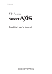
Create a sample program using WindLDR that performs the following operations:
When input I0 and input I1 are both on, output Q0 is turned on.
When either input I1 or input I2 is on, output Q1 turns on and off continuously in one second cycle.
Circuit block
Input I0
Input I1
Input I2
Q0
ON
ON
–
–
OFF
ON
–
ON
OFF
Q1
Action
Output Q0 is turned on.
Output Q1 is turned on and off in one second cycle.
Note: A group of FBs containing an output FB and all FBs connected on the left side of the output FB is called a circuit block. The output of the
output FB is the execution result of a single circuit block.
Insert input I0
1. From the WindLDR menu bar, click Home > Function Block > Terminal > I (Digital Input).
2. Move the mouse pointer to the FBD editor and click the left-mouse button.
Input I0 is inserted at the position of the mouse pointer.
SMARTAXIS FBD PROGRAMMING MANUAL FT9Y-B1386
1-3
1: OPERATION BASICS
Insert the AND (logical AND) FB
1. From the WindLDR menu bar, click Home > Function Block > Basic >AND (Logical AND).
2. Move the mouse pointer to the FBD editor and click the left-mouse button.
AND B0 is inserted at the position of the mouse pointer.
1-4
SMARTAXIS FBD PROGRAMMING MANUAL FT9Y-B1386
1: OPERATION BASICS
Connect input I0 and AND B0 with a connection line
1. From the WindLDR menu bar, click Home > Line > Draw Line.
2. Move the mouse pointer to the output connector of the input I0.
3. Click the left-mouse button and drag the line to the input 1 connector of the AND B0.
4. Release the left-mouse button.
The output connector of the input I0 and the input 1 connector of the AND B0 are connected.
SMARTAXIS FBD PROGRAMMING MANUAL FT9Y-B1386
1-5
1: OPERATION BASICS
Insert output Q0 and connect it to the output of the AND B0
1. From the WindLDR menu bar, click Home > Function Block > Terminal > Q (Digital Output).
2. Move the mouse pointer to the FBD editor and click the left-mouse button.
Output Q0 is inserted at the position of the mouse pointer.
3. Connect the output connector of the AND B0 and the input connector of the output Q0 with a connection line.
Connect them in the same manner as "Connect input I0 and AND B0 with a connection line" on page 1-5.
1-6
SMARTAXIS FBD PROGRAMMING MANUAL FT9Y-B1386
1: OPERATION BASICS
Insert input I1 and connect it to the input 2 of the AND B0
Insert input I1 in the same manner as "Insert input I0" on page 1-3 and connect it to the input 2 of the AND B0 with a connection
line in the same manner as "Connect input I0 and AND B0 with a connection line" on page 1-5.
Insert input I2 and XOR B1 and connect input I1 and input I2 to the inputs 1 and 2 of the XOR FB
Note: A single FB output connector can be connected to multiple FB input connectors. Multiple FB output connectors cannot be connected to a
single FB input connector.
SMARTAXIS FBD PROGRAMMING MANUAL FT9Y-B1386
1-7
1: OPERATION BASICS
Insert special internal relay M8121, AND B2, and output Q1 and connect them with connection lines
Note: M8121 is a special internal relay turning on and off continuously in one second cycle. For details on the special internal relay, see "Device
Addresses" - "Special Internal Relays" - "Special Internal Relay Device Addresses" on page 3-2.
Creating FBD program is completed.
1-8
SMARTAXIS FBD PROGRAMMING MANUAL FT9Y-B1386
1: OPERATION BASICS
Convert Program
1. Confirm that the program has been correctly created.
From the WindLDR menu bar, click Home > Program > Convert.
If the FBs are correctly connected, the conversion will be successful. If any errors are found, those errors are displayed in the
Info Window. Correct the program to clear those errors in order.
SMARTAXIS FBD PROGRAMMING MANUAL FT9Y-B1386
1-9
1: OPERATION BASICS
Saving a Project
1. Give the project a name and save it.
From the Application menu
, click Save As > WindLDR Project.
2. Specify the project file name as "TEST01.pjw", specify the folder to save to, and click Save.
The project is saved to the specified file.
1-10
SMARTAXIS FBD PROGRAMMING MANUAL FT9Y-B1386
1: OPERATION BASICS
Simulation
Before transferring the user program to the SmartAXIS, you can check the operation of the program in WindLDR. To check
program operation on the SmartAXIS, external devices must be connected to the SmartAXIS and inputs must be turned on and off,
but with the simulation function, input I states can also be changed in WindLDR, which enables you to check the operation of the
program.
1. From the WindLDR menu bar, select Online > Simulation > Simulation.
2. Double-click the input FB you wish to change its state.
When you turn on both input I0 and input I1, output Q0 is turned on.
When you turn on either input I1 or input i2, output Q1 is turned on and off continuously in one second cycle.
Notes:
To end the simulation function, select Online > Simulation > Simulation again.
You can monitor the state of the input connectors and output connectors of each FB. When input connectors, output connectors, and
connection lines are red, they are on. Blue indicates off.
For details on the state of unconnected input connectors of each FB, see the chapters for the FBs.
SMARTAXIS FBD PROGRAMMING MANUAL FT9Y-B1386
1-11
1: OPERATION BASICS
Download Program
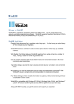
To download a user program to the SmartAXIS, the communication method must be configured in advance.
The user program can be downloaded to the SmartAXIS using WindLDR over a USB connection or an Ethernet connection. This
section describes the procedure, from configuring the communication method to downloading the user program, using a USB
connection as an example.
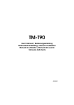
To use a USB connection, the SmartAXIS USB port must be connected to a computer using a USB cable.
Windows computer
SmartAXIS Pro
USB cable
HG9Z-XCM42 USB maintenance cable
USB port
Type A plug
Mini-B plug
USB port
(USB 2.0 Mini-B connector)
Note: To communicate with the SmartAXIS via a USB connection, the dedicated USB driver must be installed in the computer.
For the driver installation procedure, see "Appendix" in the "SmartAXIS Pro/Lite User's Manual".
Configuration Procedure
1. From the WindLDR menu bar, select Online > Communication > Set Up.
2. The Communication Settings dialog box is displayed. Click the USB tab and then click OK.
The communication method is now set to the USB connection. Next, download a user program.
3. From the WindLDR menu bar, select Online > Transfer > Download > Download.
The Download dialog box is displayed.
The user program is downloaded to the SmartAXIS when you click OK.
Notes:
The created program is downloaded to the SmartAXIS along with the function area settings.
For the function area settings, see Chapter 5 "Special Functions" in the "SmartAXIS Pro/Lite User's Manual".
1-12
SMARTAXIS FBD PROGRAMMING MANUAL FT9Y-B1386
1: OPERATION BASICS
4. When the following message is displayed, the user program download is successful.
SMARTAXIS FBD PROGRAMMING MANUAL FT9Y-B1386
1-13
1: OPERATION BASICS
Monitor Operation
You can monitor the operations of the downloaded user program using the monitor function of WindLDR.
1. After the user program is successfully downloaded, from the WindLDR menu bar, select Online > Monitor > Monitor.
The SmartAXIS state is displayed on the WindLDR screen.
2. Monitor the following operations.
When you turn on both input I0 and input I1, output Q0 is turned on.
When you turn on either input I1 or input i2, output Q1 is repeatedly turned on and off in one second cycle.
The monitor operation is complete.
Notes:
You can monitor the state of the input connectors and output connectors of each FB. When input connectors, output connectors, and
connection lines are red, they are on. Blue indicates off.
For details on the state of unconnected input connectors of each FB, see the chapters for the FBs.
1-14
SMARTAXIS FBD PROGRAMMING MANUAL FT9Y-B1386
1: OPERATION BASICS
Quit WindLDR
1. From the Application menu
, click Exit WindLDR.
WindLDR exits.
SMARTAXIS FBD PROGRAMMING MANUAL FT9Y-B1386
1-15
1: OPERATION BASICS
1-16
SMARTAXIS FBD PROGRAMMING MANUAL FT9Y-B1386
2: BASIC OPERATIONS ON THE MODULE
Introduction
You can run and stop the SmartAXIS, monitor device values, and modify settings of the SmartAXIS Pro and Touch with the LCD
and operation buttons on the module without using WindLDR. This chapter describes the basic operations of the operation
buttons.
Notes
For other functions of the SmartAXIS Pro, refer to the "SmartAXIS Pro/Lite User’s Manual".
For other functions of the SmartAXIS Touch, refer to the "SmartAXIS Touch User’s Manual".
Applicable SmartAXIS
FT1A-12
FT1A-24
FT1A-40
FT1A-48
FT1A Touch
X
X
X
X
X
Basic Operations
LCD and Operation Buttons
SmartAXIS Pro
The standard screen, the system menu,
and custom messages can be displayed
on the LCD.
System menu screen
The operation buttons are laid out on
SmartAXIS Pro as shown in the diagram
on the right.
A total of six buttons,
(left),
(up),
(down),
(right),
(ESC), and
(OK), are available to use.
RUN
Edit Program
External Memory
Configurations
RUN
Edit Program
External Memory
Configurations
Operation buttons
SmartAXIS Touch
The Touch can be operated using the
buttons displayed on the LCD.
Maintenance
Maintenance Screen
System Mode
Device Monitor
Brightness
Ladder Monitor
Ladder Start/Stop
Maintenance
System Mode
Device Monitor
Brightness
Ladder Monitor
Ladder Start/Stop
Button Operations
The button operations differ when the button is pressed and released and when the button is pressed and held.
Press/Hold
Press
Press and hold
Operation
The button is pressed for 0.1 seconds or more and less than 2 seconds and then released.
The button is pressed for 2 seconds or more and then released.
SMARTAXIS FBD PROGRAMMING MANUAL FT9Y-B1386
2-1
2: BASIC OPERATIONS ON THE MODULE
2-2
SMARTAXIS FBD PROGRAMMING MANUAL FT9Y-B1386
3: DEVICE ADDRESSES
Introduction
This chapter describes device addresses available for the SmartAXIS Pro/Lite to program FBD. Special internal relays and special
data registers are also described.
The SmartAXIS is programmed using devices such as inputs, outputs, remote inputs, remote outputs, internal relays, timers,
counters, shift registers, and data registers.
Inputs (I) are relays to receive input signals through the input terminals.
Remote inputs (I) are relays to receive input signals from external devices connected to the remote I/O slaves.
Outputs (Q) are relays to send the processed results of the user program to the output terminals.
Remote outputs (O) are relays to send output signals to external devices connected to the remote I/O slaves.
Internal relays (M) are relays used in the CPU and cannot be output to the output terminals.
Special internal relays (M) are internal relays dedicated to specific functions.
Timers (T) are relays used in the user program, available as 1-sec, 100-ms, 10-ms, and 1-ms timers.
Counters (C) are relays used in the user program, available as adding counter, reversible counter, and hour meter FBs.
Shift registers (R) are registers to shift the data bits according to pulse inputs.
Data registers (D) are registers used to store numerical data.
Special data registers (D) are dedicated to special functions.
Device Addresses
Available I/O numbers depend on the SmartAXIS type.
FT1A-12
Device
Device
Address
FT1A-24
Points
Device
Address
FT1A-40
Points
Device
Address
16
I0 - I7
I10 - I17
I20 - I27
FT1A-48
Points
Device
Address
FT1A Touch
Points
Device
Address
Points
24
I0 - I7
I10 - I17
I20 - I27
I30 - I35
30
I0 - I7
8
Input (I)*1
I0 - I7
8
I0 - I7
I10 - I17
Remote Input
(I)*1
—
—
I40 - I75
I80 - I115
I120 - I155
90
I40 - I75
I80 - I115
I120 - I155
90
I40 - I75
I80 - I115
I120 - I155
90
I40 - I75
I80 - I115
I120 - I155
90
Output (Q)*1
Q0 - Q3
4
Q0 - Q7
8
Q0 - Q7
Q10 - Q17
16
Q0 - Q7
Q10 - Q17
Q20, Q21
18
Q0 - Q3
4
Remote Output
(Q)*1
—
—
Q40 - Q61
Q80 - Q101
Q120 - Q141
54
Q40 - Q61
Q80 - Q101
Q120 - Q141
54
Q40 - Q61
Q80 - Q101
Q120 - Q141
54
Q40 - Q61
Q80 - Q101
Q120 - Q141
54
Internal Relay
(M)*1
M0 - M317
256
M0 - M1277
1024
M0 - M1277
1024
M0 - M1277
1024
M0 - M1277
1024
Special Internal
Relay (M)*1
M8000 - M8177 144
M8000 - M8177 144
M8000 - M8177 144
M8000 - M8177 144
M8000 - M8177 144
Shift Register (R) R0 - R127
128
R0 - R127
128
R0 - R127
128
R0 - R127
128
R0 - R127
128
Timer (T)
T0 - T99
100
T0 - T199
200
T0 - T199
200
T0 - T199
200
T0 - T199
200
Counter (C)
C0 - C99
100
C0 - C199
200
C0 - C199
200
C0 - C199
200
C0 - C199
200
Data Register
(D)*3
D0 - D399
400
D0 - D1999
Special Data
Register (D)
D8000 - D8199
200
D8000 - D8199
*2
*2
2000
D0 - D1999
200
D8000 - D8199
*2
2000
D0 - D1999
2000
D0 - D1999
2000
200
D8000 - D8199
200
D8000 - D8199
200
Notes:
*1 The least significant digit of input, output, internal relay, and special internal relay device address is an octal number (0 through 7). Upper digits
are decimal numbers.
*2 Out of data registers D0 through D1999, D1000 through D1999 cannot be designated as "keep" types. Retained in STOPRUN, but cleared
when the power is turned on.
*3 For SmartAXIS Pro/Lite, when you use data register ROM backup, you can initialize the data registers with the values backed up in ROM. For
details, see Chapter 5 "Special Functions" – “Data Register ROM Backup” in the SmartAXIS Pro/Lite User's Manual.
SMARTAXIS FBD PROGRAMMING MANUAL FT9Y-B1386
3-1
3: DEVICE ADDRESSES
Special Internal Relays
Special internal relays M8000 through M8177 are used for controlling the CPU operation and communication and for indicating CPU
status. All special internal relays cannot be used as destinations of advanced instructions.
Internal relays M300 through M335 are used to read input device status of the IOREF (I/O refresh) instruction.
Note: Do not change the status of reserved special internal relays, otherwise the SmartAXIS may not operate correctly.
Special Internal Relay Device Addresses
Device
Address
Description
Power OFF
Read/Write
Read/Write
M8000
Start Control
Maintained
Maintained
M8001
1-sec Clock Reset
Cleared
Cleared
Write
M8002
All Outputs OFF
Cleared
Cleared
Write
M8003
M8004
— Reserved —
User Program Execution Error
―
―
―
Cleared
Cleared
Read
M8005
Remote I/O Slave 1 Communication Error
Operating
Cleared
Read
M8006
Remote I/O Slave 2 Communication Error
Operating
Cleared
Read
M8007
Remote I/O Slave 3 Communication Error
Operating
Cleared
Read
M8010
In Daylight Saving Time Period (System version 1.10 or later)
Operating
Cleared
Read
―
―
―
M8011M8012
— Reserved —
M8013
Calendar/Clock Data Write/Adjust Error Flag
Operating
Cleared
Read
M8014
Calendar/Clock Data Read Error Flag
Operating
Cleared
Read
M8015
M8016
— Reserved —
Calendar Data Write Flag
―
―
―
Operating
Cleared
Write
M8017
Clock Data Write Flag
Operating
Cleared
Write
M8020
Calendar/Clock Data Write Flag
Operating
Cleared
Write
M8021
Clock Data Adjust Flag
Operating
Cleared
Write
―
―
―
Read/Write
M8022M8024
— Reserved —
M8025
Maintain Outputs While CPU Stopped
Maintained
Cleared
M8026
SD Memory Card Status
Maintained
Cleared
Read
M8027
SD Memory Card Writing Flag
Maintained
Cleared
Read
Cleared
Cleared
Read
Maintained
Cleared
Read
M8030
Comparison Output Reset
M8031
Gate Input
M8032
Reset Input
Maintained
Cleared
Read
M8033
Reset Status
Maintained
Cleared
Read
Comparison ON Status
Maintained
Cleared
Read
M8035
Overflow
Maintained
Cleared
Read
M8036
Underflow
Maintained
Cleared
Read
M8037
Count Direction
Maintained
Cleared
Read
M8040
Comparison Output Reset
Cleared
Cleared
Read
M8034
High-speed Counter (Group 1/I0)
M8041
M8042
High-speed Counter (Group 2/I2)
Gate Input
Maintained
Cleared
Read
Reset Input
Maintained
Cleared
Read
M8043
Comparison ON Status
Maintained
Cleared
Read
M8044
Overflow
Maintained
Cleared
Read
Cleared
Cleared
Read
Maintained
Cleared
Read
M8045
Comparison Output Reset
M8046
Gate Input
M8047
Reset Input
Maintained
Cleared
Read
M8050
Reset Status
Maintained
Cleared
Read
Comparison ON Status
Maintained
Cleared
Read
M8052
Overflow
Maintained
Cleared
Read
M8053
Underflow
Maintained
Cleared
Read
M8054
Count Direction
Maintained
Cleared
Read
M8051
3-2
CPU
Stopped
High-speed Counter (Group 3/I3)
SMARTAXIS FBD PROGRAMMING MANUAL FT9Y-B1386
3: DEVICE ADDRESSES
Device
Address
Description
CPU
Stopped
Power OFF
Read/Write
M8055
Comparison Output Reset
Cleared
Cleared
Read
M8056
Gate Input
Maintained
Cleared
Read
Read
M8057
Reset Input
Maintained
Cleared
M8060
High-speed Counter (Group 4/I5)
Comparison ON Status
Maintained
Cleared
Read
M8061
Overflow
Maintained
Cleared
Read
―
―
―
Operating
Cleared
Write
―
―
―
M8062M8075
M8076
— Reserved —
SD Memory Card Access Stop Flag
M8077M8087
— Reserved —
M8090
Group 1/I0
Maintained
Cleared
Read
M8091
Group 2/I2
Maintained
Cleared
Read
M8092
Group 3/I3
Maintained
Cleared
Read
Group 4/I5
Maintained
Cleared
Read
M8094
Group 5/I6
Maintained
Cleared
Read
M8095
Group 6/I7
Maintained
Cleared
Read
M8096M8107
— Reserved —
―
―
―
M8110
Connection 1
(ON: Connected, OFF: Not Connected)
Operating
Cleared
Read
Connection 2
(ON: Connected, OFF: Not Connected)
Operating
Cleared
Read
M8112
Connection 3
(ON: Connected, OFF: Not Connected)
Operating
Cleared
Read
M8113M8117
— Reserved —
―
―
―
Cleared
Cleared
Read
Operating
Cleared
Read
M8093
M8111
Catch Input ON/OFF Status
Connection Status
M8120
Initialize Pulse
M8121
1-sec Clock
M8122
100-ms Clock
Operating
Cleared
Read
M8123
10-ms Clock
Operating
Cleared
Read
M8124
Timer/Counter Preset Value Changed
Maintained
Cleared
Read
M8125
In-operation Output
Cleared
Cleared
Read
―
―
―
Write
Operating
Cleared
Read/Write
Read
Operating
Cleared
Read/Write
―
―
―
M8126M8153
M8154
M8155
— Reserved —
Data Register ROM Backup
M8156M8157
— Reserved —
M8160
ESC Key + Up Key
Cleared
Cleared
Read
M8161
ESC Key + Down Key
Cleared
Cleared
Read
ESC Key + Left Key
Cleared
Cleared
Read
ESC Key + Right Key
Cleared
Cleared
Read
―
―
―
M8162
Key Input Status
M8163
M8164
M8165
— Reserved —
M8166
Comparison Output Reset
Cleared
Cleared
Read
M8167
Gate Input
Maintained
Cleared
Read
Read
Reset Input
Maintained
Cleared
M8171
M8170
Comparison ON Status
Maintained
Cleared
Read
M8172
Overflow
Maintained
Cleared
Read
M8173
Comparison Output Reset
Cleared
Cleared
Read
M8174
Gate Input
Maintained
Cleared
Read
Read
M8175
High-speed Counter (Group5/I6)
Reset Input
Maintained
Cleared
M8176
High-speed Counter (Group 6/I7)
Comparison ON Status
Maintained
Cleared
Read
M8177
Overflow
Maintained
Cleared
Read
SMARTAXIS FBD PROGRAMMING MANUAL FT9Y-B1386
3-3
3: DEVICE ADDRESSES
M8000 Start Control
M8000 is used to control the operation of the CPU. The CPU stops operation when M8000 is turned off while the CPU is running.
M8000 can be turned on or off using the WindLDR Online menu. When a stop or reset input is designated, M8000 must remain on
to control the CPU operation using the stop or reset input.
M8000 maintains its status when the CPU is powered down. When the data to be maintained during power failure is broken after
the CPU has been off for a period longer than the battery backup duration, the CPU restarts operation or not as selected in
Configuration > Run/Stop Control > Run/Stop Selection at Memory Backup Error. For details, see the following
manuals.
Chapter 5 "Special Functions" - "Run/Stop Selection at Memory Backup Error" in the SmartAXIS Pro/Lite User's Manual
Chapter 3 "Project" - "4 Special Functions" - "4.4 Run/Stop Selection at Memory Backup Error" in the SmartAXIS Touch User's Manual
M8001 1-sec Clock Reset
While M8001 is on, M8121 (1-sec clock) is turned off.
M8002 All Outputs OFF
When M8002 is turned on, all outputs and remote outputs go off until M8002 is turned off. Self-maintained circuits using outputs
also go off and are not restored when M8002 is turned off.
M8004 User Program Execution Error
When an error occurs while executing a user program, M8004 turns on. The cause of the user program execution error can be
checked using Online > Monitor > Monitor, then Online > Status > Error Status > Details.
For a list of user program execution errors, see the following manuals.
Chapter 14 "Troubleshooting" - "User Program Execution Error" in the SmartAXIS Pro/Lite User's Manual
Chapter 30 "Troubleshooting" - "2 Error Information" in the SmartAXIS Touch User's Manual
M8005 Remote I/O Slave 1 Communication Error
When an error occurs during communication with remote I/O slave 1, M8005 turns on. When the error is cleared, M8005 turns off.
M8006 Remote I/O Slave 2 Communication Error
When an error occurs during communication with remote I/O slave 2, M8006 turns on. When the error is cleared, M8006 turns off.
M8007 Remote I/O Slave 3 Communication Error
When an error occurs during communication with remote I/O slave 3, M8007 turns on. When the error is cleared, M8007 turns off.
M8010 In Daylight Saving Time Period
When the daylight saving time is enabled, M8010 is turned on while in the daylight saving time period. When the daylight saving
tiem is disabled, M8010 is always off.
M8013 Calendar/Clock Data Write/Adjust Error Flag
When an error occurs while calendar/clock data is written or clock data is adjusted, M8013 turns on. If calendar/clock data is
written or clock data is adjusted successfully, M8013 turns off.
M8014 Calendar/Clock Data Read Error Flag
When an error occurs while calendar/clock data is read from the internal clock to the special data registers (D8008 to D8014),
M8014 turns on. If calendar/clock data is read successfully, M8014 turns off.
M8016 Calendar Data Write Flag
When M8016 is turned on, data in data registers D8015 through D8018 (calendar new data) are set to the internal clock.
M8017 Clock Data Write Flag
When M8017 is turned on, data in data registers D8019 through D8021 (clock new data) are set to the internal clock.
M8020 Calendar/Clock Data Write Flag
When M8020 is turned on, data in data registers D8015 through D8021 (calendar/clock new data) are set to the internal clock.
M8021 Clock Data Adjust Flag
When M8021 is turned on, the clock is adjusted with respect to seconds. If seconds are between 0 and 29 for current time,
adjustment for seconds will be set to 0 and minutes remain the same. If seconds are between 30 and 59 for current time,
adjustment for seconds will be set to 0 and minutes are incremented by one.
M8025 Maintain Outputs While CPU Stopped
Outputs are normally turned off when the CPU is stopped. M8025 is used to maintain the output statuses when the CPU is
stopped. When the CPU is stopped with M8025 turned on, the output ON/OFF statuses are maintained. When the CPU restarts,
M8025 is turned off automatically.
3-4
SMARTAXIS FBD PROGRAMMING MANUAL FT9Y-B1386
3: DEVICE ADDRESSES
M8026 SD Memory Card Status
When an SD memory card is inserted into the SmartAXIS, M8026 turns on. When an SD memory card is not inserted, M8026 turns
off.
M8027 SD Memory Card Writing Flag
While logging data is written to the SD memory card, M8027 turns on. When writing logging data is finished, M8027 turns off.
M8030-M8061 Special Internal Relays for High-speed Counter
Special internal relays used for the high-speed counter.
For details on the high-speed counter, see the following manuals.
Chapter 5 "Special Functions" - "High-Speed Counter" in the SmartAXIS Pro/Lite User's Manual
Chapter 3 "4.7 High-Speed Counter" in the SmartAXIS Touch User's Manual
M8076 SD Memory Card Access Stop Flag
Access to the SD memory card stops when M8076 is turned from off to on.
M8090-M8095 Catch Input ON/OFF Status
When a rising or falling input edge is detected during a scan, the input statuses of catch inputs Group 1/I0 through Group 6/I7 at
the moment are set to M8090 through M8095, respectively, without regard to the scan status. Only one edge is detected in one
scan. For the catch input function, see Chapter 5 "Special Functions" - "Catch Input" in the SmartAXIS Pro/Lite User's Manual.
M8110-M8112 Connection Status
When SmartAXIS and a network device are connected via the maintenance communication server, user communication server/
client, or Modbus TCP server/client, the connection status turns on. When no network devices are connected, the connection
status turns off.
These relays are always off for the 12-I/O type (SmartAXIS without Ethernet port).
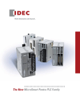
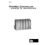
M8120 Initialize Pulse
When the CPU starts operation, M8120 turns on for a period of one scan.
1 scan time
M8120
Start
M8121 1-sec Clock
While M8001 (1-sec clock reset) is off, M8121 generates clock
pulses in 1-sec increments, with a duty ratio of 1:1 (500 ms on and
500 ms off).
M8122 100-ms Clock
M8122 always generates clock pulses in 100-ms increments,
whether M8001 is on or off, with a duty ratio of 1:1 (50 ms on and
50 ms off).
M8123 10-ms Clock
M8123 always generates clock pulses in 10-ms increments,
whether M8001 is on or off, with a duty ratio of 1:1 (5 ms on and 5
ms off).
500 ms
500 ms
M8121
1 sec
50 ms
50 ms
M8122
100 ms
5 ms
5 ms
M8123
10 ms
M8124 Timer/Counter Preset Value Changed
When timer/counter preset values are changed in the CPU module RAM, M8124 turns on. When a user program is
downloaded to the CPU from WindLDR or when the changed timer/counter preset value is cleared, M8124 turns off.
When a timer or counter is designated as a destination of an advanced instruction, the timer/counter preset value is also changed.
M8125 In-operation Output
M8125 remains on while the CPU is running.
M8154 Write Data Register values to ROM
This special internal relay is used for the data register ROM backup. When M8154 is on at the end of scan, the values of all data
registers are written to ROM. After writing values, the execution status is stored in D8133 and M8154 turns off. For details, see
Chapter 5 "Special Functions" – "Data Register ROM Backup" in the SmartAXIS Pro/Lite User's Manual.
M8155 In-operation Output
This special internal relay is used for the data register ROM backup. When M8155 turns on at the end of scan, the values in the
corresponding ROM are read and stored in the data registers specified by D8184 (start address to read) and D8185 (number of
registers to read). After reading values, the execution status is stored in D8133 and M8155 turns off. For details, see Chapter 5
"Special Functions" – "Data Register ROM Backup" in the SmartAXIS Pro/Lite User's Manual.
SMARTAXIS FBD PROGRAMMING MANUAL FT9Y-B1386
3-5
3: DEVICE ADDRESSES
M8160-M8163 Button Input Status
When the ESC and direction buttons on the SmartAXIS Pro are simultaneously pressed, the corresponding special internal relays
M8160 through M8163 turn on. When no buttons are pressed, M8160 through M8163 turn off.
M8166-M8177 Special Internal Relays for High-speed Counter
Special internal relays used for the high-speed counter.
For details on the high-speed counter, see the following manuals.
Chapter 5 "Special Functions" - "High-Speed Counter" in the SmartAXIS Pro/Lite User's Manual
Chapter 3 "Project" - "4 Special Functions" - "4.7 High-Speed Counter" in the SmartAXIS Touch User's Manual
3-6
SMARTAXIS FBD PROGRAMMING MANUAL FT9Y-B1386
3: DEVICE ADDRESSES
Special Data Registers
Note: Do not change the data in any of the reserved special data registers, otherwise the SmartAXIS may not operate correctly.
Special Data Register Device Addresses
Device Address
Description
Updated
See Page
D8000
Quantity of Inputs
When I/O initialized
3-9
D8001
Quantity of Outputs
When I/O initialized
3-9
D8002
SmartAXIS Type Information
Power-up
3-10
D8003
Memory Cartridge Information
Power-up
3-10
D8004
— Reserved —
D8005
General Error Code
D8006
User Program Execution Error Code
D8007
D8012
When error occurred
3-10
Year
D8009
D8011
—
3-10
— Reserved —
D8008
D8010
—
When error occurred
Calendar/Clock
Current Data
(Read only)
—
—
Every 500 ms
3-10
3-10
Month
Every 500 ms
Day
Every 500 ms
3-10
Day of Week
Every 500 ms
3-10
3-10
Hour
Every 500 ms
D8013
Minute
Every 500 ms
3-10
D8014
Second
Every 500 ms
3-10
D8015
Year
—
3-10
D8016
Month
—
3-10
Day
—
3-10
Day of Week
—
3-10
Hour
—
3-10
D8020
Minute
—
3-10
D8021
Second
—
3-10
D8022
Constant Scan Time Preset Value
(1 to 1,000 ms)
—
3-10
D8017
D8018
D8019
D8023
D8024
Calendar/Clock
New Data
(Write only)
Scan Time
Data
D8025
Scan Time Current Value (ms)
Every scan
3-10
Scan Time Maximum Value (ms)
At occurrence
3-10
Scan Time Minimum Value (ms)
At occurrence
3-10
D8026
Communication Mode Information (Port 2 and Port 3)
Every scan
3-10
D8027
Port 2 Slave Number
Every scan
3-11
D8028
Port 3 Slave Number
Every scan
3-11
D8029
System Software Version
Power-up
3-11
D8030
Communication Adapter Information
Power-up
3-11
D8031
Optional Cartridge Information
Power-up
3-11
D8032-D8038
— Reserved —
—
—
D8039
SD Memory Card Capacity (Megabytes)
Every 1 sec
3-11
D8040
Analog Input Value (AI0)
Every scan
3-11
D8041
Analog Input Value (AI1)
Every scan
3-11
D8042
Analog Input Value (AI2)
Every scan
3-11
D8043
Analog Input Value (AI3)
Every scan
3-11
D8044
Analog Input Value (AI4)
Every scan
3-11
D8045
Analog Input Value (AI5)
Every scan
3-11
D8046
Analog Input Value (AI6)
Every scan
3-11
D8047
Analog Input Value (AI7)
Every scan
3-11
—
—
Every scan
3-11
Preset Value
—
3-11
Reset Value
—
3-11
D8048-D8049
— Reserved —
D8050
D8051
D8052
D8053
D8054
D8055
High Word
High-speed
Counter
(Group 1/I0)
Low Word
High Word
Low Word
High Word
Low Word
Current Value / Frequency
Measurement Value (I0)
SMARTAXIS FBD PROGRAMMING MANUAL FT9Y-B1386
3-7
3: DEVICE ADDRESSES
Device Address
Description
D8056
D8057
D8058
D8059
D8060
High Word
High-speed
Counter
(Group 2/I2)
Low Word
High Word
Low Word
High Word
D8061
Low Word
D8062
High Word
D8063
Low Word
D8064
D8065
D8066
High-speed
Counter
(Group 3/I3)
High Word
Low Word
High Word
D8067
Low Word
D8068
High Word
D8069
Low Word
D8070
D8071
D8072
High-speed
Counter
(Group 4/I5)
D8073
D8074
High Word
Low Word
High Word
Low Word
See Page
Every scan
3-11
Preset Value
—
3-11
Reset Value
—
3-11
Every scan
3-11
Preset Value
—
3-11
Reset Value
—
3-11
Every scan
3-11
Preset Value
—
3-11
Reset Value
—
3-11
Every scan
3-12
Current Value / Frequency
Measurement Value (I3)
Current Value / Frequency
Measurement Value (I5)
Backlight ON Time
D8075-D8076
D8077
Updated
Current Value / Frequency
Measurement Value (I2)
— Reserved —
—
—
—
3-12
MAC Address (Read only)
Every 1 sec
3-12
IP Address (Current Data) Read only
Every 1 sec
3-12
Subnet Mask (Current Data) Read only
Every 1 sec
3-12
Default Gateway (Current Data) Read only
Every 1 sec
3-12
—
—
Connection 1 Connected IP Address
Every 1 sec
3-12
Connection 2 Connected IP Address
Every 1 sec
3-12
Connection 3 Connected IP Address
Every 1 sec
3-12
Out of Analog Input Range Status
D8078
D8079
D8080
D8081
D8082
D8083
D8084
D8085
D8086
D8087
D8088
D8089
D8090
D8091
D8092
D8093
D8094
D8095
D8096-D8109
— Reserved —
D8110
D8111
D8112
D8113
D8114
D8115
D8116
D8117
D8118
D8119
D8120
D8121
D8122-D8129
3-8
—
—
D8130
Connection 1 Connected Port Number
— Reserved —
Every 1 sec
3-12
D8131
Connection 2 Connected Port Number
Every 1 sec
3-12
D8132
Connection 3 Connected Port Number
Every 1 sec
3-12
SMARTAXIS FBD PROGRAMMING MANUAL FT9Y-B1386
3: DEVICE ADDRESSES
Device Address
D8133
Description
Data Register ROM Backup
D8134
High Word
Low Word
D8136
D8137
D8138
High Word
Low Word
High Word
D8139
Low Word
D8140
High Word
D8141
Low Word
D8142
D8143
D8144
High-speed
Counter
(Group 6/I7)
D8145
High Word
Low Word
High Word
Low Word
D8146
See Page
3-13
Every scan
3-11
Preset Value
—
3-11
Reset Value
—
3-11
Every scan
3-11
Preset Value
—
3-11
Reset Value
—
3-11
——
—
Execution Status
D8135
High-speed
Counter
(Group 5/I6)
Updated
When executing data
register ROM backup
read and write
Current Value / Frequency
Measurement Value (I6)
Current Value / Frequency
Measurement Value (I7)
— Reserved —
D8147
D8148
Communication Error Status
When error occurred
3-13
D8149
Analog Input (AI10)
Every scan
3-13
D8150
Analog Input (AI11)
Every scan
3-13
D8151
Analog Input (AI12)
Every scan
3-13
Analog Input (AI13)
Every scan
3-13
Analog Input (AI14)
Every scan
3-13
D8154
Analog Input (AI15)
Every scan
3-13
D8155
Analog Input (AI16)
Every scan
3-13
D8156
Analog Input (AI17)
Every scan
3-13
D8157
Communication Error Status
D8158
D8152
D8153
Remote I/O
Slave 1
When error occurred
3-13
Analog Input (AI20)
Every scan
3-13
D8159
Analog Input (AI21)
Every scan
3-13
D8160
Analog Input (AI22)
Every scan
3-13
Analog Input (AI23)
Every scan
3-13
Analog Input (AI24)
Every scan
3-13
D8163
Analog Input (AI25)
Every scan
3-13
D8164
Analog Input (AI26)
Every scan
3-13
D8165
Analog Input (AI27)
Every scan
3-13
D8166
Communication Error Status
D8167
D8161
D8162
Remote I/O
Slave 2
When error occurred
3-13
Analog Input (AI30)
Every scan
3-13
D8168
Analog Input (AI31)
Every scan
3-13
D8169
Analog Input (AI32)
Every scan
3-13
Analog Input (AI33)
Every scan
3-13
Analog Input (AI34)
Every scan
3-13
D8172
Analog Input (AI35)
Every scan
3-13
D8173
Analog Input (AI36)
Every scan
3-13
D8174
Analog Input (AI37)
Every scan
3-13
D8170
D8171
Remote I/O
Slave 3
D8175-D8183
D8184
D8185
D8186-D8199
— Reserved —
Data Register
ROM Backup
—
—
Start Address to Read
—
3-13
Number of Registers to Read
—
3-13
—
—
— Reserved —
D8000 Quantity of Inputs
The total of input points provided on the SmartAXIS is stored to D8000.
D8001 Quantity of Outputs
The total of output points provided on the SmartAXIS is stored to D8001.
SMARTAXIS FBD PROGRAMMING MANUAL FT9Y-B1386
3-9
3: DEVICE ADDRESSES
D8002 SmartAXIS Type Information
Information about the SmartAXIS type is stored to D8002.
0:
1:
2:
3:
4:
SmartAXIS
SmartAXIS
SmartAXIS
SmartAXIS
SmartAXIS
Pro/Lite
Pro/Lite
Pro/Lite
Pro/Lite
Touch
12-I/O
24-I/O
40-I/O
48-I/O
type
type
type
type
D8003 Memory Cartridge Information
When an optional memory cartridge is installed on the SmartAXIS cartridge connector, information about the user program stored
on the memory cartridge is stored to D8003.
0:
1:
2:
3:
255:
SmartAXIS Pro/Lite 12-I/O type
SmartAXIS Pro/Lite 24-I/O type
SmartAXIS Pro/Lite 40-I/O type
SmartAXIS Pro/Lite 48-I/O type
The memory cartridge does not store any user program.
D8005 General Error Code
SmartAXIS general error information is stored to D8005. When a general error occurs, the bit corresponding to the error occurred
turns on.
The general error and user program execution error can be cleared by writing “1” to the most significant bit of D8005 using a user
program.
For details on general error codes, see the following manuals.
Chapter 14 "Troubleshooting" - "General Error Codes" in the SmartAXIS Pro/Lite User's Manual
Chapter 30 "Troubleshooting" - "2 Error Information" - "2.1 General Error Codes" in the SmartAXIS Touch User's Manual
D8006 User Program Execution Error Code
SmartAXIS user program execution error information is stored to D8006. When a user program execution error occurs, the error
code corresponding to the error occurred is stored to D8006.
For details on user program execution error codes, see the following manuals.
Chapter 14 "Troubleshooting" - "User Program Execution Error" in the SmartAXIS Pro/Lite User's Manual
Chapter 30 "Troubleshooting" - "2 Error Information" - "2.2 Program Execution Error" in the SmartAXIS Touch User's Manual
D8008-D8021 Calendar/Clock Data
D8008 through D8021 are used for reading calendar/clock data from the internal clock and for writing calendar/clock data to the
internal clock.
D8022-D8025 Scan Time Data
D8022 through D8025 are special data registers for checking the scan time and configuring the constant scan time.
For details on the scan time, see the following manuals.
Chapter 5 "Special Functions" - "Constant Scan Time" in the SmartAXIS Pro/Lite User's Manual
Chapter 12 "Control Function" in the SmartAXIS Touch User's Manual
D8026 Communication Mode Information (Port 2 and Port 3)
Communication mode information of port 2 and port 3 is stored to D8026.
Bit
15
D8026
Bit
8
Bit
7
0
0
0
Port 3
0:
1:
2:
3:
3-10
Bit
0
Bit
4
0
0
0
0
0
Port 2
Maintenance Communication
User Communication
Modbus RTU Master
Modbus RTU Slave
SMARTAXIS FBD PROGRAMMING MANUAL FT9Y-B1386
3: DEVICE ADDRESSES
D8027-D8028 Slave Number
The slave number is stored to D8027 and D8028 when the communication mode for port 2 and 3 is maintenance communication
or Modbus RTU slave.
The slave number can be specified with either a constant or a data register in the function area settings. When data register is
specified, the slave number can be changed by storing the slave number in D8027 and D8028.
D8027: Port 2 Slave Number
D8028: Port 3 Slave Number
For details on maintenance communication, see Chapter 9 “Maintenance Communication” - “Maintenance Communication via
Expansion Communication Port” in the SmartAXIS Pro/Lite User's Manual.
For details on Modbus RTU slaves, see Chapter 11 “Modbus Communication” - “Modbus Communication via RS-232C/RS-485” in
the SmartAXIS Pro/Lite User's Manual. For SmartAXIS Touch maintenance communication and Modbus RTU slaves, see Chapter 13
"Troubleshooting" - "Reading Error Data" in the SmartAXIS Pro/Lite User's Manual.
D8029 System Software Version
The PLC system software version number is stored to D8029. This value is indicated in the PLC status dialog box called from the
WindLDR menu bar. Select Online > Monitor > Monitor, then select Online > Status. See Chapter 13 "Troubleshooting" "Reading Error Data" in the SmartAXIS Pro/Lite User's Manual.
D8030 Communication Adapter Information
Information about the communication adapters installed on the port 2 and port 3 connectors is stored to D8030.
Bit
15
Bit
8
Bit
7
D8030
1
Bit
0
0
0
Port 3 Port 2
0:
1:
RS232C communication adapter is installed
RS485 communication adapter is installed or no communication adapter is installed
D8031 Optional Cartridge Information
Information about the optional cartridge installed on the SmartAXIS is stored to D8031.
Bit
15
Bit
8
Bit
7
D8031
1
Bit
0
0
0
SD memory card
0:
1:
2:
3:
Memory cartridge
No optional cartridge is installed
Memory cartridge is installed
SD memory card is installed
Memory cartridge and SD memory card are installed
D8039 SD Memory Card Capacity
The capacity of the inserted SD or SDHC (maximum size 32 GB) memory card in megabytes is stored to D8039.
D8040-D8047 Analog Input Value
The analog input values (0 to 10 VDC) to the analog input terminals are converted to digital values (0 to 1000) and stored to the
corresponding special data registers.
Linear conversions can be configured for the analog input (AI) FBs. Even when the linear conversions are configured for AI FBs,
the special data registers store the analog values (0 to 1000) before the linear conversions are applied.
D8040=AI0, D8041=AI1, D8042=AI2, D8043=AI3, D8044=AI4, D8045=AI5, D8046=AI6, D8047=AI7
D8050-D8073, D8134-D8145 High-speed Counter and Frequency Measurement
These special data registers are used with the high-speed counter function and the frequency measurement function.
For details on the high-speed counter, see the following manuals.
Chapter 5 "Special Functions" - "High-Speed Counter" in the SmartAXIS Pro/Lite User's Manual
Chapter 3 "Project" - "4 Special Functions" - "4.7 High-Speed Counter" in the SmartAXIS Touch User's Manual
SMARTAXIS FBD PROGRAMMING MANUAL FT9Y-B1386
3-11
3: DEVICE ADDRESSES
D8074 Backlight ON Time
The backlight ON time is stored. The backlight ON time can be configured by changing the value in D8074 between 1 to 65,535
seconds. When D8074 is 0, the backlight is always ON. The backlight ON time can also be changed with the HMI function. For
details on the HMI function , see Chapter 6 "HMI Function" - "Changing Backlight ON Time" in the SmartAXIS Pro/Lite User's
Manual.
D8077 Out of Analog Input Range Status
When an analog input value is 11V or higher, the corresponding D8077 bit turns on. When an analog input value is lower than 11V,
the corresponding D8077 bit turns off.
The assignment of each analog input is as follows.
Bit
15
Bit
8
D8077
Bit
7
6
5
4
3
2
1
Bit
0
0
0
0
0
0
0
0
0
Analog Input 0
Analog Input 1
Analog Input 2
Analog Input 3
Analog Input 4
Analog Input 5
Analog Input 6
Analog Input 7
D8078-D8083 MAC Address (Read only)
MAC address of the SmartAXIS is stored to the special data registers in hexadecimal as shown below.
Example) MAC address: AA-BB-CC-DD-EE-FF
D8078=AAh, D8079=BBh, D8080=CCh, D8081=DDh, D8082=EEh, D8083=FFh
D8084-D8087 IP Address (Current Data) Read only
IP address of the SmartAXIS is stored to the special data registers as shown below.
Example) IP address: aaa.bbb.ccc.ddd
D8084=aaa, D8085=bbb, D8086=ccc, D8087=ddd
D8088-D8091 Subnet Mask (Current Data) Read only
Subnet mask of the SmartAXIS is stored to the special data registers as shown below.
Example) Subnet mask: aaa.bbb.ccc.ddd
D8088=aaa, D8089=bbb, D8090=ccc, D8091=ddd
D8092-D8095 Default Gateway (Current Data) Read only
Default gateway of the SmartAXIS is stored to the special data registers as shown below.
Example) Default gateway: aaa.bbb.ccc.ddd
D8092=aaa, D8093=bbb, D8094=ccc, D8095=ddd
D8110-D8121 Connection (1 through 3) Connected IP Address
The IP address of the remote host accessing the connection 1 through 3 is stored in special data registers.
Example) Connection 1 Connected IP Address: aaa.bbb.ccc.ddd
D8110=aaa, D8111=bbb, D8112=ccc, D8113=ddd
D8130-D8132 Connection Connected Port Number
When connections are established with other network devices, the port numbers of the connected network devices are stored in
these special data registers.
D8130 : Connection 1 Connected Port Number
D8131 : Connection 2 Connected Port Number
D8132 : Connection 3 Connected Port Number
3-12
SMARTAXIS FBD PROGRAMMING MANUAL FT9Y-B1386
3: DEVICE ADDRESSES
D8133 Data Register ROM Backup Execution Status
This special data register is used for the data register ROM backup. Stores the execution status for writing and reading.
1: Processing
2: Normal termination
3: Cannot access ROM
4: Invalid values are stored in D8184 (starting address to read) and D8185 (number of registers to read)
5: Valid data could not be read from ROM
For details, see Chapter 5 "Special Functions" – “Data Register ROM Backup” in the SmartAXIS Pro/Lite User's Manual.
D8148, D8157, D8166 Remote I/O Communication Error Status
When a communication error occurs between the remote I/O communication slave and master, the details of the communication
error are stored in these special data registers.
D8148 : Remote I/O Slave 1 Communication Error Status
D8157 : Remote I/O Slave 2 Communication Error Status
D8166 : Remote I/O Slave 3 Communication Error Status
D8149-D8156, D8158-D8165, D8167-D8174 Remote I/O Analog Input Values
The analog input values (0 to 10 VDC) to the remote I/O analog inputs are converted to digital values (0 to 1000) and stored in the
special data registers allocated to each remote I/O slave.
Linear conversions can be configured for the analog input (AI) FBs. Even when the linear conversions are configured for AI FBs,
the special data registers store the analog values (0 to 1000) before the linear conversions are applied.
D8149=AI10, D8150=AI11, D8151=AI12, D8152=AI13, D8153=AI14, D8154=AI15, D8155=AI16, D8156=AI17
D8158=AI20, D8159=AI21, D8160=AI22, D8161=AI23, D8162=AI24, D8163=AI25, D8164=AI26, D8165=AI27
D8167=AI30, D8168=AI31, D8169=AI32, D8170=AI33, D8171=AI34, D8172=AI35, D8173=AI36, D8174=AI37
D8184 Data Register ROM Backup Start Address to Read
This special data register is used for the data register ROM backup and stores the start address of the data registers to read. For
details, see Chapter 5 "Special Functions" – "Data Register ROM Backup" in the SmartAXIS Pro/Lite User's Manual.
D8185 Data Register ROM Backup Number of Registers to Read
This special data register is used for the data register ROM backup and stores the number of data registers to read. For details,
see Chapter 5 "Special Functions" – "Data Register ROM Backup" in the SmartAXIS Pro/Lite User's Manual.
SMARTAXIS FBD PROGRAMMING MANUAL FT9Y-B1386
3-13
3: DEVICE ADDRESSES
3-14
SMARTAXIS FBD PROGRAMMING MANUAL FT9Y-B1386
4: FB REFERENCE
This chapter describes the SmartAXIS series FB function.
Note: The programming and operations on the SmartAXIS FBD program require specialist knowledge.
To make effective use of the SmartAXIS, take the time to develop a thorough understanding of the contents in this manual and the programming.
FB List
Input FB
Symbol
Name and Diagram
Output
Inversion
Refer to
Inputs ON/OFF information from an external to the SmartAXIS.
–
5-1
Special internal relays can be used as bit inputs for FBs in the
SmartAXIS. Special function is allocated to each special internal relay.
For details on the individual special internal relays, see "Device
Addresses" - "Special Internal Relay Device Addresses" on page 3-2.
–
5-2
Outputs ON/OFF state of a shift register device.
–
5-3
The analog input values (0 to 10V DC) for the analog input terminals
are converted to digital values (0 to 1,000) and output. With the analog
input linear conversion function, the analog input value can be linearly
conversion within a range of -32,768 to 32,767.
–
5-4
Function
Output
Inversion
Refer to
Outputs ON/OFF information from the SmartAXIS to an external
device.
–
6-1
A bit unit FB used internally by the SmartAXIS.
–
6-2
Function
Digital Input
I
I
OUT
Special Internal Relay
SM
SM
OUT
Shift Register
R
R
OUT
Analog Input
AI
AI
AOUT
Output FB
Symbol
Name and Diagram
Digital Output
Q
IN
Q
OUT
Internal Relay
M
IN
M
OUT
SMARTAXIS FBD PROGRAMMING MANUAL FT9Y-B1386
4-1
4: FB REFERENCE
Logical Operation FB
Symbol
Name and Diagram
Output
Inversion
Refer to
Implements logical AND for a maximum of four input signals (ON/
OFF) and outputs the result.
–
7-1
Implements negative logical AND for a maximum of four input
signals (ON/OFF) and outputs the result.
–
7-2
Implements logical OR for a maximum of four input signals (ON/
OFF) and outputs the result.
–
7-3
Implements negative logical OR for a maximum of four input signals
(ON/OFF) and outputs the result.
–
7-4
Implements exclusive logical OR for a maximum of two input signals
(ON/OFF) and outputs the result.
–
7-5
Implements negative exclusive logical OR for a maximum of two
input signals (ON/OFF) and outputs the result.
–
7-6
Outputs the result of negating the input signal (ON/OFF).
–
7-7
Turns on the output for one scan when the input signal turns from
off to on.
–
7-8
Turns on the output for one scan when the input signal turns from
on to off.
–
7-9
A truth table for the output can be configured corresponding to the
16 patterns combination of the four input signals, and TRUTH FB
outputs the result according to the table.
X
7-10
Function
Logical AND
AND
IN1
IN2
IN3
IN4
&
OUT
Negative Logical AND
NAND
IN1
IN2
IN3
IN4
&
OUT
≥1
OUT
Logical OR
OR
IN1
IN2
IN3
IN4
Negative Logical OR
NOR
IN1
IN2
IN3
IN4
≥1
OUT
Exclusive Logical OR
XOR
IN1
IN2
=1
OUT
Negative Exclusive Logical OR
XNOR
IN1
IN2
=1
OUT
1
OUT
SOTU
OUT
SOTD
OUT
TRUTH
OUT
Negation
NOT
IN
Shot up
SOTU
IN
Shot down
SOTD
IN
Truth Table
TRUTH
4-2
IN1
IN2
IN3
IN4
SMARTAXIS FBD PROGRAMMING MANUAL FT9Y-B1386
4: FB REFERENCE
Timer FB
Symbol
Name and Diagram
On-delay Count Up Timer
TIMU
TRG
TIMU
100 ms
OUT
On-delay Count Down Timer
TIMD
TRG
TIMD
100 ms
OUT
Off-delay Count Up Timer
TIMOU
TRG
RST
TIMOU
100 ms
OUT
Off-delay Count Down Timer
TIMOD
TRG
RST
TIMOD
100 ms
OUT
On/off-delay Timer
TIMCU
TRG
RST
TIMCU
100 ms
OUT
Function
Output
Inversion
Refer to
After the execution input turns on, the output turns on when the
on-delay time elapses. The current value is incremented from zero
to the preset value.
–
8-1
After the execution input turns on, the output turns on when the
on-delay time elapses. The current value is decremented from the
preset value to zero.
–
8-5
When the execution input turns on, the output turns on. After the
execution input turns off, the output turns off when the off-delay
time elapses. The current value is incremented from zero to the
preset value.
–
8-7
When the execution input turns on, the output turns on. After the
execution input turns off, the output turns off when the off-delay
time elapses. The current value is decremented from the preset
values to zero.
–
8-9
After the execution input turns on, the output turns on when the
on-delay time elapses. After the execution input turns off, the
output turns off when the off-delay time elapses.
–
8-11
Single Shot Pulse
SPULS
TRG
RST
SPULS
100 ms
OUT
After the execution input turns on, the output turns on for the
configured time period.
–
8-14
DTIM
100 ms
OUT
The output is turned on and off according to the configured ON
and OFF time.
–
8-16
OUT
The output is turned on for the length of random time within the
configured range of time.
–
8-19
Output
Inversion
Refer to
When the clock input is turned on, the current value is
incremented by one. The output turns on when the current value
reaches the preset value.
–
9-1
When the clock input is turned on, the current value is incremented
or decremented by one according to the up/down selection input.
The current value is compared with ON/OFF thresholds. The output
turns on or off according to the comparison result.
–
9-3
Accumulates the ON duration of the execution input in hours,
minutes, and seconds.
The output turns on when the accumulated time reaches the
configured time.
–
9-7
Dual Timer
DTIM
EN
Random Pulse Output
RPULS
EN
RPULS
100 ms
Counter FB
Symbol
Name and Diagram
Function
Adding Counter
CNT
RST
UP
CNT
OUT
Up/Down Selection Reversible Counter
CUD
PRST
CLK
U/D
CUD
OUT
HOUR
OUT
Hour Meter
HOUR
EN
RST
SMARTAXIS FBD PROGRAMMING MANUAL FT9Y-B1386
4-3
4: FB REFERENCE
Shift Register FB
Symbol
Output
Inversion
Refer to
X
10-1
Output
Inversion
Refer to
Two inputs values are compared and the output turns on or off
according to the comparison result.
X
11-1
The comparison input value and the ON/OFF thresholds are
compared and the output turns on or off according to the
comparison result.
X
11-3
The comparison input value and the upper/lower limits are
compared and the output turns on or off according to the
comparison result.
X
11-5
Output
Inversion
Refer to
X
12-1
Output
Inversion
Refer to
Name and Diagram
Function
Shift Register
SFR
TRG
RST
DI
DIR
SFR
OUT
When the execution input turns on, the shift registers are shifted
to the specified shift direction.
Data Comparison FB
Symbol
Name and Diagram
Function
Data Comparison
CMP
EN
DAT1
DAT2
CMP
OUT
Schmitt Trigger
EN
DATA
ON
OFF
STTG
STTG
OUT
Range Comparison
EN
DATA
UL
LL
RCMP
RCMP
OUT
Data Conversion FB
Symbol
Name and Diagram
Function
Alternate Output
ALT
TRG
SET
RST
ALT
OUT
Sets/resets the output.
Week Programmer FB
Symbol
Name and Diagram
Function
Weekly Timer
EN
INI
WEEK
WEEK
OUT
Compares the specified day of the week, ON time, and OFF time
with the current time and outputs the result.
–
13-1
YEAR
OUT
Compares the specified date with the current date and outputs the
result.
–
13-12
Function
Output
Inversion
Refer to
X
14-1
Yearly Timer
EN
INI
YEAR
Interface FB
Symbol
Name and Diagram
Message
MSG
4-4
EN
MSG
OUT
Displays data such as text and device values on the LCD on the
SmartAXIS Pro.
SMARTAXIS FBD PROGRAMMING MANUAL FT9Y-B1386
4: FB REFERENCE
Pulse FB
Symbol
Name and Diagram
Function
Output
Inversion
Refer to
Pulse Output
PULS
EN
INI
PULS
OUT
Outputs pulses at the specified frequency.
X
15-1
OUT
Outputs pulses at the specified frequency and duty cycle.
X
15-6
RAMP
OUT
Outputs pulses with the frequency change function.
X
15-11
ZRN
OUT
Outputs pulses with the different pulse frequency corresponding to
the on/off state of a deceleration signal.
X
15-21
Output pulses with the frequency change function according to the
settings configured in the frequency table.
X
15-26
Function
Output
Inversion
Refer to
Saves the values of the specified devices in the specified data
format as a CSV file to the SD memory card.
–
16-1
Saves the values of the previous number of scans for the specified
device in the specified data format as a CSV file to the SD memory
card.
–
16-8
Function
Output
Inversion
Refer to
–
17-1
Pulse Width Modulation
PWM
EN
INI
PWM
Ramp Pulse Output
RAMP
EN
INI
DIR
Zero Return
ZRN
EN
INI
DE
Advanced Ramp
ARAMP
EN
INI
INT
ARAMP
OUT
Data Logging FB
Symbol
Name and Diagram
Data Log
DLOG
EN
DLOG
OUT
TRACE
OUT
Data Trace
TRACE
EN
Script FB
Symbol
Name and Diagram
Script
SCRPT
EN
SCRPT
OUT
Enables you to program complicated processing with the script
language that supports conditional branching, logical operations,
arithmetic operations, and functions.
SMARTAXIS FBD PROGRAMMING MANUAL FT9Y-B1386
4-5
4: FB REFERENCE
Special FB
Symbol
Name and Diagram
Output
Inversion
Refer to
Operates the high-speed counter configured in the function area
settings. Turns on/off the high-speed counter gate input/reset
input/clear input.
X
18-1
When the set input turns on, the output turns on and keeps on.
When the reset input turns on, the output turns off.
X
18-3
Function
High-speed Counter
HSC
GT
RST
CLR
HSC
OUT
RSFF
OUT
RS Flip-flop
RSFF
4-6
SET
RST
SMARTAXIS FBD PROGRAMMING MANUAL FT9Y-B1386
4: FB REFERENCE
Advanced Instruction Applicable SmartAXIS
FB
Group
Input
Output
Logical
Operation
Timer
Counter
Shift Register
Data
Comparison
Data
Conversion
Week
Programmer
Interface
Pulse
Name
Digital Input
Special Internal Relay
Shift Register
Analog Input
Digital Output
Script
Special
Q
Internal Relay
Logical AND
Negative Logical AND
Logical OR
Negative Logical OR
Exclusive Logical OR
Negative Exclusive Logical OR
Negation
Shot up
Shot down
Truth Table
On-delay Count Up Timer
On-delay Count Down Timer
Off-delay Count Up Timer
Off-delay Count Down Timer
On/off-delay Timer
Single Shot Pulse
Dual Timer
Random Pulse Output
Adding Counter
Up/Down Selection Reversible
Counter
Hour Meter
Shift Register
Data Comparison
Schmitt Trigger
Range Comparison
Alternate Output
Weekly Timer
Yearly Timer
X
X
Applicable SmartAXIS
FT1A-24
FT1A-40
AC
DC
AC
DC
X
X
X
X
X
X
X
X
X
X
X
X
X
X
X
X
X
X
X
X
FT1A-48
AC
DC
X
X
X
X
X
X
X
X
X
X
FT1A
Touch
X
X
X
X
X
M
X
X
X
X
X
X
X
X
X
AND
NAND
OR
NOR
XOR
XNOR
NOT
SOTU
SOTD
TRUTH
TIMU
TIMD
TIMOU
TIMOD
TIMCU
SPULS
DTIM
RPULS
CNT
X
X
X
X
X
X
X
X
X
X
X
X
X
X
X
X
X
X
X
X
X
X
X
X
X
X
X
X
X
X
X
X
X
X
X
X
X
X
X
X
X
X
X
X
X
X
X
X
X
X
X
X
X
X
X
X
X
X
X
X
X
X
X
X
X
X
X
X
X
X
X
X
X
X
X
X
X
X
X
X
X
X
X
X
X
X
X
X
X
X
X
X
X
X
X
X
X
X
X
X
X
X
X
X
X
X
X
X
X
X
X
X
X
X
X
X
X
X
X
X
X
X
X
X
X
X
X
X
X
X
X
X
X
X
X
X
X
X
X
X
X
X
X
X
X
X
X
X
X
X
X
X
X
X
X
X
X
X
X
X
X
X
X
X
X
X
X
X
X
X
X
CUD
X
X
X
X
X
X
X
X
X
HOUR
SFR
CMP
STTG
RCMP
X
X
X
X
X
X
X
X
X
X
X
X
X
X
X
X
X
X
X
X
X
X
X
X
X
X
X
X
X
X
X
X
X
X
X
X
X
X
X
X
X
X
X
X
X
ALT
X
X
X
X
X
X
X
X
X
WEEK
YEAR
X
X
X
X
X
X
X
X
X
X
X
X
X
X
X
X
X
X
X
(Note 1) (Note 1) (Note 1) (Note 1) (Note
Message
MSG
Pulse Output
PULS
–
–
–
–
–
Pulse Width Modulation
PWM
–
–
–
–
–
Ramp Pulse Output
RAMP
–
–
–
–
–
ZRN
–
–
–
–
–
Advanced Ramp
ARMP
–
–
–
–
–
Data Log
Data Trace
Script
High-speed Counter
RS Flip-flop
DLOG
TRACE
SCRPT
HSC
RSFF
–
–
X
–
X
–
–
X
X
X
–
–
X
–
X
–
–
X
X
X
X
X
X
–
X
Zero Return
Data Logging
Symbol
I
M
R
AI
FT1A-12
AC
DC
X
X
X
X
X
X
X
X
X
X
X
X
X
1) (Note 1) (Note 1) (Note 1)
X
X
X
(Note 2)
X
X
X
(Note 2)
X
X
X
(Note 3) (Note 3) (Note 3)
X
X
X
X
X
X
(Note 3) (Note 3) (Note 3)
X
X
X
X
X
X
X
X
X
X
–
X
X
X
X
X
X
–
–
–
–
–
–
–
–
X
X
X
Note 1: The MSG FB can be used only with SmartAXIS Pro.
Note 2: When using RAMP1 in single-pulse output mode, PULS3 and PWM3 cannot be used. When using RAMP2 in single-pulse output mode,
PULS4 and PWM4 cannot be used.
Note 3: When using RAMP1 or ARAMP1 in dual-pulse output mode, RAMP2 or ARAMP2 cannot be used.
SMARTAXIS FBD PROGRAMMING MANUAL FT9Y-B1386
4-7
4: FB REFERENCE
Applicable Data Types
Data type
FB
Group
Input
Output
W
Name
L
F
Long
Float
–
Symbol
Word
Integer
Digital Input
I
–
–
–
–
M
–
–
–
–
–
Shift Register
R
–
–
–
–
–
Analog Input
AI
X*1
X*1
–
–
–
Digital Output
Q
–
–
–
–
–
Internal Relay
M
–
–
–
–
–
AND
–
–
–
–
–
NAND
–
–
–
–
–
OR
–
–
–
–
–
Negative Logical OR
NOR
–
–
–
–
–
Exclusive Logical OR
XOR
–
–
–
–
–
XNOR
–
–
–
–
–
Negation
NOT
–
–
–
–
–
Shot up
SOTU
–
–
–
–
–
Shot down
SOTD
–
–
–
–
–
Truth Table
TRUTH
–
–
–
–
–
Negative Logical AND
Logical OR
Timer
D
Double
word
Special Internal Relay
Logical AND
Logical
Operation
I
Negative Exclusive Logical OR
On-delay Count Up Timer
TIMU
X
–
–
–
–
On-delay Count Down Timer
TIMD
X
–
–
–
–
Off-delay Count Up Timer
TIMOU
X
–
–
–
–
Off-delay Count Down Timer
TIMOD
X
–
–
–
–
On/off-delay Timer
TIMCU
X
–
–
–
–
Single Shot Pulse
SPULS
X
–
–
–
–
Dual Timer
DTIM
X
–
–
–
–
Random Pulse Output
RPULS
X
–
–
–
–
Adding Counter
CNT
X
–
X
–
–
Counter
Up/Down Selection Reversible
Counter
CUD
X
–
X
–
–
HOUR
X
–
–
–
–
Shift Register
Shift Register
SFR
–
–
–
–
–
Hour Meter
Data
Comparison
Data
Conversion
Data Comparison
CMP
X
X
X
X
–
Schmitt Trigger
STTG
X
X
X
X
–
Range Comparison
RCMP
X
X
X
X
–
ALT
–
–
–
–
–
Alternate Output
Week
Programmer
Weekly Timer
WEEK
–
–
–
–
–
Yearly Timer
YEAR
–
–
–
–
–
Interface
Message
MSG
X
X
X
X
X
Pulse Output
PULS
–
–
–
–
–
Pulse Width Modulation
PWM
–
–
–
–
–
Ramp Pulse Output
RAMP
–
–
–
–
–
–
Pulse
Zero Return
Data Logging
Script
Special
ZRN
–
–
–
–
Advanced Ramp
ARMP
–
–
–
–
–
Data Log
DLOG
X
X
X
X
X
Data Trace
TRACE
X
X
X
X
X
Script
SCRPT
X
X
X
X
X
High-speed Counter
HSC
X
–
X
–
–
RS Flip-flop
RSFF
–
–
–
–
–
*1 When using the analog input cartridge (AI2 to AI5) of the Touch (transistor output type), configure the data type of AI FB in the function area
settings. For configuring the function area settings, see Chapter 3 "4.15 Analog Cartridge" in the "SmartAXIS Touch User's Manual".
4-8
SMARTAXIS FBD PROGRAMMING MANUAL FT9Y-B1386
4: FB REFERENCE
FB Specifications
This section describes the FB specifications.
Basic FB configuration
All FBs are composed of a FB symbol, input connectors (4 maximum), an output connector, and a block number. FBs operate according
to the state of the input connectors and the internal parameters of the FB, and output the result from the output connector.
2
B0100
3
4
&
1
Name
1
2
3
4
Description
FB symbol
The symbol that indicates the FB type.
Block number
(device address)
Unique number to identify each function block. The block number is automatically assigned in ascending order
from zero. The block number can be changed to a desired number. However, the block numbers already used
in any other FBs cannot be used.
If a tag name and comment are configured for the device address, they are also displayed.
Input connector
Connectors for inputting the output states of other FBs to the FB. Connect the output connectors of the other
FBs to these input connectors. The type of output connector (bit/analog) can be connected varies depending
on the input connectors of each FB. Depending on each input connector, FBs may be used with the input
connectors unconnected. For details, see the descriptions of each FB. Input connectors receiving a bit state
can be configured as Inverted so that the inverted bit state can be input to the FB.
Output connector
The connector for outputting the result of the FB operation. FBs have only a single bit output (on/off) or an
analog output. The result of the FB operation can be input to another FB by connecting the output connector
to an input connector of the FB. If the output connector is bit output, the result of the FB operation can be
inverted and output. For the list of FBs that support output inversion, see "FB List" on page 4-1. Output
connectors of FBs other than the output FBs (digital output/internal relay) must be connected to the input
connectors of other FBs.
FB devices
This list shows the devices that can be used in FBD programs.
Symbol
Name
Attributes in FBD
programs
Description
R
Devices for incorporating on/off information from external devices to the
SmartAXIS. The state can be changed by changing the state of the external input
or by the forced I/O function*1.
I
Digital Input
Q
Digital Output
R/W
Devices for outputting on/off information from the SmartAXIS to external devices. The
state can be changed with the forced I/O function*1, the FBD program, or the SCRPT FB.
M
Internal Relay
R/W
Devices for receiving FB output internally. To incorporate the output results of a FB as
looped-back input, insert an internal relay in between the output connector and the input
connector of the FB. The state can be changed with a FBD program or the SCRPT FB.
M
Special Internal
Relay
R
Devices for referring to special internal relays. The state can be changed with the
SCRPT FB.
R
Shift Register
R
Bit devices used with the SFR FB. The state can be changed with the SFR FB and
the SCRPT FB.
AI
Analog Input
R
Devices for incorporating analog input signals from external devices the SmartAXIS.
T
Timer
R
Timers used internally in the SmartAXIS. These are used with the timer FBs.
C
Counter
R
Counters used internally in the SmartAXIS. These are used with the counter FBs.
D
Data Register
–
Word devices used for storing numeric data. The value can be changed with the
SCRPT FB.
B
Block Relay
R
Devices that indicate the output state of FBs other than timers and counters.
*1 Using WindLDR, inputs and outputs can be forcibly turned on and off. For details, see Chapter 5 "Special Functions" - "Forced I/O Function" in
the SmartAXIS Pro/Lite User's Manual.
SMARTAXIS FBD PROGRAMMING MANUAL FT9Y-B1386
4-9
4: FB REFERENCE
Notes:
Devices refer to memory areas that are prepared in advanced for specific purposes in the SmartAXIS, and they are identified by the device
type I, Q, M, R, AI, T, C, D, and B and the address. Device values refer to the values stored in the memory areas specified by the device
addresses.
Devices that can be configured vary depending on each FB parameter. You may also be able to configure constants instead of devices.
For details on SmartAXIS device types, see "Device Addresses" on page 3-1.
Data types
When using counter FBs, comparison FBs data logging FBs, and script FBs, the data type can be set. Arithmetic operations can be
performed on a variety of data by specifying the data type.
■Data type W (word), I (integer), D (double word), L (long)
The unit and range of data that can be processed with data type W (word), I (integer), D (double word), and L (long) is as follows.
Data Type
Abbreviation
Name
Number of Used
Data Registers
Processable unit
Data Range
W
Word
1
Unsigned 16 bits
0 - 65,535
I
Integer
1
Signed 15 bits
-32,768 - 32,767
D
Double word
2
Unsigned 32 bits
0 - 4,294,967,295
L
Long
2
Signed 31 bits
-2,147,483,648 - 2,147,483,647
For the data types that can be used with each FB, see "Applicable Data Types" on page 4-8.
Storage Method of 32-bit Data
32-bit D (double word) and L (long word) type data is stored in devices in the following manner according to the selection in
Function Area Settings under Device Settings.
For applicable devices and FBs, see Chapter 5 "Special Functions" - "Storage Method of 32-bit Data" in the SmartAXIS Pro/Lite
User's Manual.
Word device:
When From Upper Word is selected under Device Settings.
When D0000 is specified as the storage location, the upper word is stored in D0000 and the lower word is stored in
D0001.
Double word data (constant)
Upper word
Lower word
1 2 3 4 5 6 7 8
D0000:
1 2 3 4
Upper word
D0001:
5 6 7 8
Lower word
(Hexadecimal)
When From Lower Word is selected under Device Settings.
When D0000 is specified as the storage location, the lower word is stored in D0000 and the upper word is stored in
D0001.
Double word data (constant)
Upper word
Lower word
1 2 3 4 5 6 7 8
D0000:
5 6 7 8
Lower word
D0001:
1 2 3 4
Upper word
(Hexadecimal)
Bit device:
When R000 is specified as the storage location, the lower word is stored in the range R000 - R015 and the
upper word is stored in the range R016-R031.
Double word data (constant)
Upper word
Lower word
1 2 3 4 5 6 7 8
(Hexadecimal)
R015
R000 - R015
5 6 7 8
R031
R016 - R031:
4-10
R000
Lower word
R016
1 2 3 4
Upper word
SMARTAXIS FBD PROGRAMMING MANUAL FT9Y-B1386
4: FB REFERENCE
■Data Type F (Float)
Handling numeric values in floating point arithmetic operations
With the SmartAXIS series, F (float), which means the floating point type, can be specified as the data type for FBs that use
floating point. For FBs that use floating point, two consecutive data registers starting from the specified data register are used as
a pair in the same manner as the integer types D (double word) and L (long). The SmartAXIS series floating point type data format
conforms to the IEEE (US Institute of Electrical and Electronics Engineers) standard for the single precision storage format as
explained next.
Single precision floating point values in IEEE 754 (32 bits)
Single precision floating point values in IEEE 754 are expressed with a total of 32 bits (2 words) using 1 bit for the sign s, 8 bits for
the exponent e, and 23 bits for the significand f. The sign bit indicates the sign of the expressed value (positive or negative). The
exponent is an 8 bit signed integer with a value from -126 to 127.
Bit
31
Bit
30
Bit
23
s
e (exponent) [bit 30 to 23]
Bit
22
Bit
0
f (significand) [bit 22 to 0]
Value from -126 to 127
Represents 1.xxx after the decimal
Sign bit (0: positive, 1: negative)
Example:
s
e
0 01111101
f
10000000000000000000000
1.5×2
-2
The table below shows the correspondence between values in the three fields of s, e, and f, and the value expressed as a single
precision floating point value. When a value other than a normal number or 0 is input to a FB that uses floating point, a user
program execution error occurs and special internal relay M8004 (user program execution error) turns on.
Value
Exponent e
Significand f
Representation in WindLDR
±0
e=0
f=0
0.0
Denormal numbers
e=0
f>0
-1.175495E-38 to 1.175495E-38
Normal numbers
0<e<255
Arbitrary
-3.402823E+38 to -1.175495E-38
1.175495E-38 to 3.402823E+38
f=0
INF
f>0
NAN
±∞ (± infinity)
Not a Number
e=255
SMARTAXIS FBD PROGRAMMING MANUAL FT9Y-B1386
4-11
4: FB REFERENCE
Inverting FB input/output
The state of the FB output connector connected to an input connector can be inverted and incorporated. The inverted input value
to the FB is the same as when the NOT FB (negation FB) is connected immediately before the input connector. The result of the FB
operation can also be inverted and output. At that time, the output value from the FB is the same as when the NOT FB (negation
FB) is connected immediately after the output connector.
■Input inversion
IN1
FB
Output of FB connected to IN1
State of IN1 incorporated in FB
ON
OFF
OFF
ON
FB operation result
FB output
ON
OFF
OFF
ON
■Output inversion
FB
FB analog input
The SmartAXIS is equipped with analog input ports. Analog values input to the analog input ports can be processed in FBD programs.
FBs that can handle analog values as input are the CMP (Data Comparison), STTG (Schmitt Trigger), and RCMP (Range Comparison)
FBs.
I1
I
B002
AI1
AI
CMP
AI2
AI
The CMP FB in the above FBD program compares analog input AI1 with AI2 and outputs the result when input I1 is on.
Note:
The comparison FBs (CMP/STTG/RCMP) are capable of handling data of data type W (word), I (integer), D (double word), and L (long), but
output from analog input FBs can only be connected when the comparison FB data type is I (integer).
When handling analog input values as FB input, use the analog input (AI) FB. Analog input values (0 to 1000) can be linearly converted in the
range of -32768 to 32767 using the AI FB. For details on the AI FB, see "The input FB" on page 5-1.
The analog values before the linear conversion are stored in special data registers (D8040 to D8047, D8149 to D8156, D8158 to D8165,
D8167 to D8174). For details, see "Device Addresses" on page 3-1.
4-12
SMARTAXIS FBD PROGRAMMING MANUAL FT9Y-B1386
4: FB REFERENCE
FB input/output connectors and parameters
This section describes FB input/output connectors and parameters. The function of the connectors and parameters can be
identified by the symbols. The list of symbols, their descriptions, and data formats are shown next.
Input connector
Symbol
Description
Input format
IN
Input
EN, TRG
Execution input
ON/OFF
ON/OFF
SET
Set input
ON/OFF
RST
Reset input
ON/OFF
PRST
Preset input
ON/OFF
UP
Up clock input
ON/OFF
CLK
Clock input
ON/OFF
U/D
Up/down selection input
ON/OFF
DI
Data input
ON/OFF
DIR
Control direction input
ON/OFF
INI
Initialization input
ON/OFF
DE
Deceleration signal input
ON/OFF
INT
Interrupt input
ON/OFF
DAT, DATA
Comparison value
Analog
UL
Upper limit
Analog
LL
Lower limit
Analog
ON
ON threshold
Analog
OFF
OFF threshold
Analog
Output connector
Symbol
Description
Input format
OUT
Output
ON/OFF
AOUT
Analog output
Analog
Parameter
Symbol
MIN
Description
Linear conversion minimum
MAX
Linear conversion maximum
S1, S2
Control register, folder name, script ID, number of parameter tabs
D1, D2
Operation status, monitor register, execution status, execution result
TP
Timer FB preset value
TU
Time unit
CP
Counter FB preset value
OP
Operation mode, data type, high-speed counter group
R
Start shift register
N, n
Number of constituent bits, pulse output port number
PRI
Priority
SMARTAXIS FBD PROGRAMMING MANUAL FT9Y-B1386
4-13
4: FB REFERENCE
FB connection lines
The lines that connect FB input connectors and output connectors are called connection lines. FB input connectors can be
connected to the output connectors of other FBs, but more than one output connectors cannot be connected to a single input
connector. In this situation, use a logical operation FB as shown in the following example.
I
I
Q
1
SM
Q
SM
The FB output connector can be connected to more than one input connectors of the other FBs. There is no limit to the number of
input connectors that an output connector can be connected to.
I
TIMU
Q
There is no limit to the number of FBs that a
single output connector can be connected to.
M
Note:
The output connector for bit output (on/off) cannot be connected to an analog input connector.
FB input connectors cannot be connected each other and FB output connectors also can not be connected each other.
To incorporate the output results of a FB as looped-back input, an output FB (digital output/internal relay) must be inserted in between the
output connector and the input connector of the FB.
I
4-14
1
TIMU
I
TIMU
SMARTAXIS FBD PROGRAMMING MANUAL FT9Y-B1386
Q
4: FB REFERENCE
FBD programs
FBD program
A group of FBs connected to an output FB is called a circuit block. The minimum configuration of a circuit block is composed of an
input FB and an output FB. The FB operation results are passed to FBs connected by the connection line. The group of all circuit
blocks created in the program is called the FBD program.
Example of a minimum configuration of a circuit block:
Connection line
Input FB
Output FB
I
Q
Scan time
In the FBD program, the processing to execute all of the programmed FBs is called one scan, and the time required to execute the
program for one scan is called the scan time.
FBD program execution
For FBD programs, all of the FBs composing circuit blocks and connected to an output FB (digital output/internal relay) are
executed sequentially from the input FBs. FBs other than the input FBs incorporate the operation results of the other FBs
connected to the input connectors, process the operation, and output the result from the output connector. The FBs are executed
in order from the FBs connected to the input FBs, and the execution of a single circuit block is complete when the data is passed
to the output FB (digital output/internal relay). When all the circuit blocks have completed executing, program execution for one
scan is complete.
Note:
After the Q0, Q1, and Qx circuit blocks have executed, the circuit blocks are executed in M0000, M0001, and Mx order.
FBs that are not connected to output FBs (digital output/internal relay), in other words, the FBs that do not compose a circuit block are not
executed.
For input FBs, the most recent input state acquired by refreshing the I/O at the end of the scan is output from the output connector.
Output connectors of output FBs (digital output/internal relay) can be connected to the input connectors of the other FBs. Output from the
output connector of output FBs is the state of the output FB in the previous scan. For example, in the FBD program in the following diagram,
Q4 turns on four scans after I10 turns on.
I10
Q1
Q2
Q3
Q4
I
Q
Q
Q
Q
To turn on all the output FBs simultaneously when I10 is turned on, created a FBD program as shown in the following diagram.
I10
Q1
I
Q
Q2
Q
Q3
Q
Q4
Q
SMARTAXIS FBD PROGRAMMING MANUAL FT9Y-B1386
4-15
4: FB REFERENCE
4-16
SMARTAXIS FBD PROGRAMMING MANUAL FT9Y-B1386
5: THE INPUT FB
This chapter describes the input FB of the SmartAXIS series.
I (Digital Input)
A function block to use the state (on/off) of a digital input.
Symbol
I
OUT
Operation
The digital input FB outputs the on/off state of the digital input. Specify a digital input number to the FB.
Applicable SmartAXIS
FT1A-12
FT1A-24
FT1A-40
FT1A-48
FT1A Touch
X
X
X
X
X
Parameters
Parameter
Function
Number
I
Input
–
Output
OUT
Parameters
–
Range
Input number
–
I0 to I155
*1
Description
Unique number to identify the digital input function block.
Specify a digital input number. However, the digital input numbers already
used in any other digital input FBs cannot be used.
–
Output
–
–
–
Outputs the on/off state of the specified digital input.
–
–
*1 The range for the digital input varies depending on the SmartAXIS type.
Product series
Digital input (I)
12-I/O type
I0 to I7 (8 inputs)
24-I/O type
I0 to I17 (16 inputs), I40 to I75 (30 inputs), I80 to I115 (30 inputs), I120 to I155 (30 inputs)
40-I/O type
I0 to I27 (24 inputs), I40 to I75 (30 inputs), I80 to I115 (30 inputs), I120 to I155 (30 inputs)
48-I/O type
I0 to I35 (30 inputs), I40 to I75 (30 inputs), I80 to I115 (30 inputs), I120 to I155 (30 inputs)
Touch
I0 to I7 (8 inputs)
SMARTAXIS FBD PROGRAMMING MANUAL FT9Y-B1386
5-1
5: THE INPUT FB
SM (Special Internal Relay)
A function block to use the state (on/off) of a special internal relay.
Symbol
SM
OUT
Operation
The special internal relay FB outputs the on/off state of the special internal relay. Specify a special internal relay number to the FB.
Note: For special internal relay numbers and functions, see "Device Addresses" on page 3-1.
Applicable SmartAXIS
FT1A-12
FT1A-24
FT1A-40
FT1A-48
FT1A Touch
X
X
X
X
X
Parameters
Parameter
Number
5-2
Function
M
Input
–
Output
OUT
Parameters
–
Internal relay
number
–
Output
Range
M8000 to
M8177
–
–
–
Description
Unique number to identify the special internal relay function block.
Specify a special internal relay number. However, the special internal relay
numbers already used in any other special internal relay FBs cannot be used.
–
Outputs the on/off state of the specified special internal relay.
–
SMARTAXIS FBD PROGRAMMING MANUAL FT9Y-B1386
–
5: THE INPUT FB
R (Shift Register)
A function block to use the state (on/off) of a shift register.
Symbol
R
OUT
Operation
The shift register FB outputs the on/off state of the shift register. Specify a shift register number to the FB.
Note: Operations on the shift register are performed with the SFR FB. For the SFR FB, see "The shift register FB" on page 10-1.
Applicable SmartAXIS
FT1A-12
FT1A-24
FT1A-40
FT1A-48
FT1A Touch
X
X
X
X
X
Parameters
Parameter
Number
Function
R
Input
–
Output
OUT
Parameters
–
Shift register
number
–
Output
Range
R0 to R127
–
–
–
Description
Unique number to identify the shift register function block.
Specify a shift register number. However, the shift register numbers already
used in any other shift register FBs cannot be used.
–
Outputs the on/off state of the specified shift register.
–
SMARTAXIS FBD PROGRAMMING MANUAL FT9Y-B1386
–
5-3
5: THE INPUT FB
AI (Analog Input)
Linearly converts the analog input value (0 to 1000) and outputs the converted value.
Symbol
AI
AOUT
Operation
The analog input FB linearly converts the analog input value (0 to 1000) and outputs the converted value. Specify an analog input
terminal number.
Applicable SmartAXIS
FT1A-12
FT1A-24
FT1A-40
FT1A-48
FT1A Touch
X
X
X
X
X
Parameters
Parameter
Function
Number
AI
Input
–
Output
Range
Analog input
number
AI0 to AI37
–
AOUT
Description
Analog output
*1
Unique number to identify the analog input FB.
Specify an analog input terminal number. However, the analog input numbers
already used in any other analog input FBs cannot be used.
–
–
–
The analog input FB linearly converts the value (0 to 1000) of the specified
analog input terminal and outputs the converted value in the range between
the linear conversion minimum and maximum values.
The analog input value before the linear conversion is stored in the special
data register.*1
MIN
Linear
conversion
minimum
-32768 to
32767 *2
Specifies the minimum value in the range between -32768 and 32767 for the
linear conversion. Set this parameter to a value that is smaller than the linear
conversion maximum value.
MAX
Linear
conversion
maximum
-32768 to
32767 *2
Specifies the maximum value in the range between -32768 and 32767 for the
linear conversion. Set this parameter to a value that is larger than the linear
conversion minimum value.
Parameters
*1 The range for the analog input terminal number varies depending on the SmartAXIS type. The special data registers are assigned to the analog
input terminals individually.
*2 When using the analog input cartridge (AI2 to AI5) of the Touch (transistor output type), the analog input FB linear conversion function cannot
be used. Configure the linear conversion in the function area settings. For configuring the function area settings, see Chapter 3 "4.15 Analog
Cartridge" in the "SmartAXIS Touch User's Manual".
Product series
12-I/O type
24-I/O type
40-I/O type
48-I/O type
5-4
Analog input terminal
Special data register
AI0 to AI1 (2 inputs)
D8040 to D8041
AI0 to AI3 (4 inputs)
D8040 to D8043
AI10 to AI17 (8 inputs)
D8149 to D8156
AI20 to AI27 (8 inputs)
D8158 to D8165
AI30 to AI37 (8 inputs)
D8167 to D8174
AI0 to AI5 (6 inputs)
D8040 to D8045
AI10 to AI17 (8 inputs)
D8149 to D8156
AI20 to AI27 (8 inputs)
D8158 to D8165
AI30 to AI37 (8 inputs)
D8167 to D8174
AI0 to AI7 (8 inputs)
D8040 to D8047
AI10 to AI17 (8 inputs)
D8149 to D8156
AI20 to AI27 (8 inputs)
D8158 to D8165
AI30 to AI37 (8 inputs)
D8167 to D8174
SMARTAXIS FBD PROGRAMMING MANUAL FT9Y-B1386
5: THE INPUT FB
Product series
Analog input terminal
Touch (Relay
output type)
Touch (Transistor
output type)
Special data register
AI0 to AI1 (2 inputs)
D8040 to D8041
AI10 to AI17 (8 inputs)
D8149 to D8156
AI20 to AI27 (8 inputs)
D8158 to D8165
AI30 to AI37 (8 inputs)
D8167 to D8174
AI0 to AI1 (2 inputs)
D8040 to D8041
AI2 to AI3 (2 inputs)
D8176 to D8177
AI4 to AI5 (2 inputs)
D8186 to D8187
AI10 to AI17 (8 inputs)
D8149 to D8156
AI20 to AI27 (8 inputs)
D8158 to D8165
AI30 to AI37 (8 inputs)
D8167 to D8174
Operation Example of the linear conversion
Linear conversion
Maximum
Value after linear
conversion
Minimum
0
Value before
linear conversion
1,000
Example: When the minimum is -5,000 and the maximum is 10,000, an analog input value of 600 is linearly converted into 4,000.
10,000
4,000
-5,000
0
600
1,000
SMARTAXIS FBD PROGRAMMING MANUAL FT9Y-B1386
5-5
5: THE INPUT FB
5-6
SMARTAXIS FBD PROGRAMMING MANUAL FT9Y-B1386
6: THE OUTPUT FB
This chapter describes the output FB of the SmartAXIS series.
Q (Digital Output)
Outputs the state (on/off) input to the FB to the specified external output.
Symbol
Q
IN
OUT
Operation
The digital output FB outputs the on/off state of the input (IN) to the specified external output. Specify an external output number
as the output number.
Note: The output state of the digital output FB is off at the first scan.
Applicable SmartAXIS
FT1A-12
FT1A-24
FT1A-40
FT1A-48
FT1A Touch
X
X
X
X
X
Parameters
Parameter
Function
Range
Description
Unique number to identify the digital output function block. Specify an
external output number. However, the digital output numbers already used in
any other digital output FBs cannot be used.
Number
Q
Digital output
number
Q0 to Q141*1
Input
IN
Input
On/off
Output
OUT
Output
–
Parameters
–
–
–
Any function block having digital output (on/off) can be connected to the
input. The on/off state of the input (IN) is output to the external output.
Outputs the on/off state of the input (IN) at the previous scan.
–
*1 The range for the output number varies depending on the SmartAXIS type.
Type
Digital Output (Q)
12-I/O type
Q0 to Q3 (4 outputs)
24-I/O type
Q0 to Q7 (8 outputs), Q40 to Q61 (18 outputs), Q80 to Q101 (18 outputs), Q120 to Q141 (18 outputs)
40-I/O type
Q0 to Q17 (16 outputs), Q40 to Q61 (18 outputs), Q80 to Q101 (18 outputs), Q120 to Q141 (18 outputs)
48-I/O type
Q0 to Q21 (18 outputs), Q40 to Q61 (18 outputs), Q80 to Q101 (18 outputs), Q120 to Q141 (18 outputs)
Touch
Q0 to Q3 (4 outputs)
SMARTAXIS FBD PROGRAMMING MANUAL FT9Y-B1386
6-1
6: THE OUTPUT FB
M (Internal Relay)
Outputs the input state (on/off) to the specified internal relay.
Symbol
M
IN
OUT
Operation
The internal relay FB outputs the on/off state of the input (IN) at the previous scan from the output (OUT). Specify an internal
relay number.
Notes:
The output state of internal relay FB can be maintained when the SmartAXIS starts the operation using the keep designation. For details on
the keep designation, see the following chapter.
Chapter 5 "Special Functions" - "Keep and clear devices" in the SmartAXIS Pro/Lite User's Manual
Chapter 3 "Projects" - "4 Special Functions" - "Keep and Clear Control Devices" in the SmartAXIS Touch User's Manual
When a FB is connected to the input connector of the internal relay FB and the on/off state of the internal relay is changed with the button
operations on the SmartAXIS or WindLDR monitor dialog box, the changed state is immediately overwritten with the output state of the
connected FB.
Applicable SmartAXIS
FT1A-12
FT1A-24
FT1A-40
FT1A-48
FT1A Touch
X
X
X
X
X
Parameters
Parameter
Function
Range
Description
Number
M
Internal relay
number
M0 to M1277*1
Unique number to identify the internal relay FB.
The internal relay number is automatically assigned in ascending order from
zero. The internal relay number can be changed to a desired number.
However, the internal relay numbers already used in any other internal relay
FBs cannot be used.
Input
IN
Input
On/off
Any function block having digital output (on/off) can be connected to the
input.
Output
OUT
Parameters
–
Output
–
–
Outputs the on/off state of the input (IN) at the previous scan.
–
*1 M0 to M317 for the 12-I/O type.
6-2
SMARTAXIS FBD PROGRAMMING MANUAL FT9Y-B1386
–
7: THE LOGICAL OPERATION FB
The logical operation function blocks perform logical operations on the input signals and output the result.
AND (Logical AND)
Calculates the logical AND on the input signals and outputs the result.
Symbol
&
IN1
IN2
IN3
IN4
OUT
Operation
The AND FB calculates the logical AND on a maximum of four input signals (ON/OFF) and outputs the result.
Applicable SmartAXIS
FT1A-12
FT1A-24
FT1A-40
FT1A-48
FT1A Touch
X
X
X
X
X
Parameters
Parameter
Number
Function
B
Range
Block number
B0 to B999
IN1
On/off
–
IN2
On/off
–
IN3
On/off
–
IN4
On/off
–
Output
OUT
Output
–
Parameters
–
Input
–
Description
*1
Unique number to identify each function block.
The block number is automatically assigned in ascending order from zero.
The block number can be changed to a desired number. However, the block
numbers already used in any other FBs cannot be used.
Any function block having digital output (on/off) can be connected to each
input. Unconnected inputs are handled as ON. However, all inputs cannot be
unconnected.
Outputs the result of logical AND on IN1 through IN4.*2
–
–
*1 B0 to B199 for the 12-I/O type.
*2 The result of logical AND on the on/off states of the inputs IN1 through IN4 is shown below.
IN1
IN2
IN3
IN4
OUT
0
0
0
0
0
0
0
0
1
0
0
0
1
0
0
0
0
1
1
0
0
1
0
0
0
0
1
0
1
0
0
1
1
0
0
0
1
1
1
0
1
0
0
0
0
1
0
0
1
0
1
0
1
0
0
1
0
1
1
0
1
1
0
0
0
1
1
0
1
0
1
1
1
0
0
1
1
1
1
1
SMARTAXIS FBD PROGRAMMING MANUAL FT9Y-B1386
7-1
7: THE LOGICAL OPERATION FB
NAND (Negative Logical AND)
Calculates the negative logical AND on the input signals and outputs the result.
Symbol
&
IN1
IN2
IN3
IN4
OUT
Operation
The NAND FB calculates the negative logical AND on a maximum of four input signals (ON/OFF) and outputs the result.
Applicable SmartAXIS
FT1A-12
FT1A-24
FT1A-40
FT1A-48
FT1A Touch
X
X
X
X
X
Parameters
Parameter
Number
Function
B
Range
Block number
B0 to B999 *1
IN1
On/off
–
IN2
On/off
–
IN3
On/off
–
IN4
On/off
–
Output
OUT
Output
Parameters
–
Input
–
–
Description
Unique number to identify each function block.
The block number is automatically assigned in ascending order from zero.
The block number can be changed to a desired number. However, the block
numbers already used in any other FBs cannot be used.
Any function block having digital output (on/off) can be connected to each
input. Unconnected inputs are handled as ON. However, all inputs cannot be
unconnected.
Outputs the result of negative logical AND on IN1 through IN4.*2
–
*1 B0 to B199 for the 12-I/O type.
*2 The result of negative logical AND on the on/off states of the inputs IN1 through IN4 is shown below.
7-2
IN1
IN2
IN3
IN4
OUT
0
0
0
0
1
0
0
0
1
1
0
0
1
0
1
0
0
1
1
1
0
1
0
0
1
0
1
0
1
1
0
1
1
0
1
0
1
1
1
1
1
0
0
0
1
1
0
0
1
1
1
0
1
0
1
1
0
1
1
1
1
1
0
0
1
1
1
0
1
1
1
1
1
0
1
1
1
1
1
0
SMARTAXIS FBD PROGRAMMING MANUAL FT9Y-B1386
–
7: THE LOGICAL OPERATION FB
OR (Logical OR)
Calculates the logical OR on the input signals and outputs the result.
Symbol
≥1
IN1
IN2
IN3
IN4
OUT
Operation
The OR FB calculates the logical OR on a maximum of four input signals (ON/OFF) and outputs the result.
Applicable SmartAXIS
FT1A-12
FT1A-24
FT1A-40
FT1A-48
FT1A Touch
X
X
X
X
X
Parameters
Parameter
Number
Function
B
Range
Block number
B0 to B999
IN1
On/off
–
IN2
On/off
–
IN3
On/off
–
IN4
On/off
–
Output
OUT
Output
–
Parameters
–
Input
–
Description
*1
Unique number to identify each function block.
The block number is automatically assigned in ascending order from zero.
The block number can be changed to a desired number. However, the block
numbers already used in any other FBs cannot be used.
Any function block having digital output (on/off) can be connected to each
input. Unconnected inputs are handled as OFF. However, all inputs cannot be
unconnected.
Outputs the result of logical OR on IN1 through IN4.*2
–
–
*1 B0 to B199 for the 12-I/O type.
*2 The result of logical OR on the on/off states the inputs IN1 through IN4 is shown below.
IN1
IN2
IN3
IN4
OUT
0
0
0
0
0
0
0
0
1
1
0
0
1
0
1
0
0
1
1
1
0
1
0
0
1
0
1
0
1
1
0
1
1
0
1
0
1
1
1
1
1
0
0
0
1
1
0
0
1
1
1
0
1
0
1
1
0
1
1
1
1
1
0
0
1
1
1
0
1
1
1
1
1
0
1
1
1
1
1
1
SMARTAXIS FBD PROGRAMMING MANUAL FT9Y-B1386
7-3
7: THE LOGICAL OPERATION FB
NOR (Negative Logical OR)
Calculates the negative logical OR on the input signals and outputs the result.
Symbol
≥1
IN1
IN2
IN3
IN4
OUT
Operation
The NOR FB calculates the negative logical OR on a maximum of four input signals (ON/OFF) and outputs the result.
Applicable SmartAXIS
FT1A-12
FT1A-24
FT1A-40
FT1A-48
FT1A Touch
X
X
X
X
X
Parameters
Parameter
Number
Function
B
Range
Block number
B0 to B999 *1
IN1
On/off
–
IN2
On/off
–
IN3
On/off
–
IN4
On/off
–
Output
OUT
Output
Parameters
–
Input
–
–
Description
Unique number to identify each function block.
The block number is automatically assigned in ascending order from zero.
The block number can be changed to a desired number. However, the block
numbers already used in any other FBs cannot be used.
Any function block having digital output (on/off) can be connected to each
input. Unconnected inputs are handled as OFF. However, all inputs cannot be
unconnected.
Outputs the result of negative logical OR on IN1 through IN4.*2
–
*1 B0 to B199 for the 12-I/O type.
*2 The result of negative logical OR on the on/off states of the inputs IN1 through IN4 is shown below.
7-4
IN1
IN2
IN3
IN4
OUT
0
0
0
0
1
0
0
0
1
0
0
0
1
0
0
0
0
1
1
0
0
1
0
0
0
0
1
0
1
0
0
1
1
0
0
0
1
1
1
0
1
0
0
0
0
1
0
0
1
0
1
0
1
0
0
1
0
1
1
0
1
1
0
0
0
1
1
0
1
0
1
1
1
0
0
1
1
1
1
0
SMARTAXIS FBD PROGRAMMING MANUAL FT9Y-B1386
–
7: THE LOGICAL OPERATION FB
XOR (Exclusive Logical OR)
Calculates the exclusive logical OR on the input signals and outputs the result.
Symbol
=1
IN1
IN2
OUT
Operation
The XOR FB calculates the exclusive logical OR on a maximum of two input signals (ON/OFF) and outputs the result.
Applicable SmartAXIS
FT1A-12
FT1A-24
FT1A-40
FT1A-48
FT1A Touch
X
X
X
X
X
Parameters
Parameter
Number
Function
B
Range
Block number
B0 to B999
IN1
On/off
–
IN2
On/off
–
Output
OUT
Output
–
Parameters
–
Input
–
Description
*1
Unique number to identify each function block.
The block number is automatically assigned in ascending order from zero.
The block number can be changed to a desired number. However, the block
numbers already used in any other FBs cannot be used.
Any function block having digital output (on/off) can be connected to each
input. Unconnected inputs are handled as OFF. However, all inputs cannot be
unconnected.
Outputs the result of exclusive logical OR on IN1 through IN2.*2
–
–
*1 B0 to B199 for the 12-I/O type.
*2 The result of exclusive logical OR on the on/off states of the inputs IN1 through IN2 is shown below.
IN1
IN2
OUT
0
0
0
0
1
1
1
0
1
1
1
0
SMARTAXIS FBD PROGRAMMING MANUAL FT9Y-B1386
7-5
7: THE LOGICAL OPERATION FB
XNOR (Negative Exclusive Logical OR)
Calculates the negative exclusive logical OR on the input signals and outputs the result.
Symbol
=1
IN1
IN2
OUT
Operation
The XNOR FB calculates the negative exclusive logical OR on a maximum of two input signals (ON/OFF) and outputs the result.
Applicable SmartAXIS
FT1A-12
FT1A-24
FT1A-40
FT1A-48
FT1A Touch
X
X
X
X
X
Parameters
Parameter
Number
Function
B
Range
Block number
B0 to B999 *1
IN1
On/off
–
IN2
On/off
–
Output
OUT
Output
–
Parameters
–
Input
–
Description
Unique number to identify each function block.
The block number is automatically assigned in ascending order from zero.
The block number can be changed to a desired number. However, the block
numbers already used in any other FBs cannot be used.
Any function block having digital output (on/off) can be connected to each
input. Unconnected inputs are handled as OFF. However, all inputs cannot be
unconnected.
Outputs the result of negative exclusive logical OR on IN1 through IN2.*2
–
–
*1 B0 to B199 for the 12-I/O type.
*2 The result of negative exclusive logical OR on the on/off states of the inputs IN1 through IN2 is shown below.
7-6
IN1
IN2
OUT
0
0
1
0
1
0
1
0
0
1
1
1
SMARTAXIS FBD PROGRAMMING MANUAL FT9Y-B1386
7: THE LOGICAL OPERATION FB
NOT (Negation)
Calculates the negation of the input signal and outputs the result.
Symbol
1
IN
OUT
Operation
The NOT FB outputs the result of negating the input signal (ON/OFF).
Applicable SmartAXIS
FT1A-12
FT1A-24
FT1A-40
FT1A-48
FT1A Touch
X
X
X
X
X
Parameters
Parameter
Number
Function
B
Range
Block number
B0 to B999
Description
*1
Unique number to identify each function block.
The block number is automatically assigned in ascending order from zero.
The block number can be changed to a desired number. However, the block
numbers already used in any other FBs cannot be used.
Input
IN
On/off
–
Any function block having digital output (on/off) can be connected.
Output
OUT
On/off
–
Outputs the result of negating the input (IN).*2
Parameters
–
–
–
–
*1 B0 to B199 for the 12-I/O type.
*2 The result of negating input IN is shown below.
IN
OUT
0
1
1
0
SMARTAXIS FBD PROGRAMMING MANUAL FT9Y-B1386
7-7
7: THE LOGICAL OPERATION FB
SOTU (Shot Up)
Turns on the output for one scan when the input signal changes from off to on.
Symbol
SOTU
IN
OUT
Operation
The SOTU FB turns on the output for one scan when the input signal changes from OFF to ON.
Applicable SmartAXIS
FT1A-12
FT1A-24
FT1A-40
FT1A-48
FT1A Touch
X
X
X
X
X
Parameters
Parameter
Function
Range
B0 to B999 *1
Description
Unique number to identify each function block.
The block number is automatically assigned in ascending order from zero.
The block number can be changed to a desired number. However, the block
numbers already used in any other FBs cannot be used.
Number
B
Block number
Input
IN
On/off
–
Any function block having digital output (on/off) can be connected.
Output
OUT
On/off
–
The output turns on for an interval of one scan when the input (IN) changes
from OFF to ON.*2
Parameters
–
–
–
–
*1 B0 to B199 for the 12-I/O type.
*2 The timing chart of the SOTU is shown below.
ON
IN
OFF
OUT
ON
OFF
One scan
7-8
SMARTAXIS FBD PROGRAMMING MANUAL FT9Y-B1386
7: THE LOGICAL OPERATION FB
SOTD (Shot Down)
Turns on the output for one scan when the input signal changes from on to off.
Symbol
SOTD
IN
OUT
Operation
The SOTD FB turns on the output for one scan when the input signal changes from ON to OFF.
Applicable SmartAXIS
FT1A-12
FT1A-24
FT1A-40
FT1A-48
FT1A Touch
X
X
X
X
X
Parameters
Parameter
Function
Range
B0 to B999
Description
Number
B
Block number
Input
IN
On/off
–
Any function block having digital output (on/off) can be connected.
Output
OUT
On/off
–
The output turns on for an interval of one scan when the input (IN) changes
from ON to OFF.*2
Parameters
–
–
–
–
*1
Unique number to identify each function block.
The block number is automatically assigned in ascending order from zero.
The block number can be changed to a desired number. However, the block
numbers already used in any other FBs cannot be used.
*1 B0 to B199 for the 12-I/O type.
*2 The timing chart of the SOTD is shown below.
ON
IN
OFF
OUT
ON
OFF
One scan
SMARTAXIS FBD PROGRAMMING MANUAL FT9Y-B1386
7-9
7: THE LOGICAL OPERATION FB
TRUTH (Truth Table)
Processes the input signals according to the configured truth table and outputs the result.
Symbol
TRUTH
IN1
IN2
IN3
IN4
OUT
Operation
The TRUTH FB turns on the output according to the truth table configured for the bit patterns of a maximum of four input signals
(ON/OFF) and outputs the result.
Truth table
IN1
0
0
0
0
0
0
0
0
1
1
1
1
1
1
1
1
IN2
0
0
0
0
1
1
1
1
0
0
0
0
1
1
1
1
IN3
0
0
1
1
0
0
1
1
0
0
1
1
0
0
1
1
IN4
0
1
0
1
0
1
0
1
0
1
0
1
0
1
0
1
OUT
(*)
(*)
(*)
(*)
(*)
(*)
(*)
(*)
(*)
(*)
(*)
(*)
(*)
(*)
(*)
(*)
Bits
15 14 13 12 11 10
9
8
7
6
5
4
3
2
1
0
S1
Applicable SmartAXIS
FT1A-12
FT1A-24
FT1A-40
FT1A-48
FT1A Touch
X
X
X
X
X
Parameters
Parameter
Number
Input
Output
Parameters
Function
B
Range
Block number
B0 to B999 *1
IN1
On/off
–
IN2
On/off
–
IN3
On/off
–
IN4
On/off
–
OUT
Output
–
S1
Description
Truth table
Unique number to identify each function block.
The block number is automatically assigned in ascending order from zero.
The block number can be changed to a desired number. However, the block
numbers already used in any other FBs cannot be used.
Any function block having digital output (on/off) can be connected to each
input. Unconnected inputs are handled as OFF. However, all inputs cannot be
unconnected.
Outputs the result according to the configured truth table.
Outputs (on/off) can be configured for all 16 bit patterns of the IN1 through
IN4.
On/off
*1 B0 to B199 for the 12-I/O type.
Valid Devices
Parameter
S1
7-10
Function
Truth table
I
Q
M
R
T
TC
TP
C
CC
CP
B
D
AI
Constant
–
–
–
–
–
–
–
–
–
–
–
–
–
X
SMARTAXIS FBD PROGRAMMING MANUAL FT9Y-B1386
8: THE TIMER FB
The timer FBs are used in a variety of ways, such as to delay the change of an output state for a specified time interval or to
output pulses in accordance with configured values.
TIMU (On-delay Count Up Timer)
When the execution input turns on, counting starts, and the current value is incremented. When the elapsed time reaches the
specified on-delay time, the output turns on.
Symbol
TRG
TIMU
1 sec
OUT
TRG
TIMU
100 ms
OUT
TRG
TIMU
10 ms
OUT
TRG
TIMU
1 ms
OUT
Operation
When the execution input (TRG) is off, the current value is 0 and the output (OUT) is off.
When the execution input turns on, the current value starts being incremented.
While the execution input is on, the current value is incremented, and when it reaches the preset value (TP), the counting stops
and the output turns on.
After the counting stops, the current value is held and the output keeps on until the execution input turns off.
Applicable SmartAXIS
FT1A-12
FT1A-24
FT1A-40
FT1A-48
FT1A Touch
X
X
X
X
X
Parameters
Parameter
Function
Number
T
Input
Output
Range
Timer number
T0 to T199
TRG
Execution
input
On/off
OUT
Output
Description
*1
Unique number to identify the Timer function block.
The timer number is automatically assigned in ascending order from zero.
The timer number can be changed to a desired number. However, the timer
numbers already used in any other timer FBs cannot be used.
When the execution input turns on, counting starts. While the execution
input is on, the current value is incremented until it reaches the preset value.
When the execution input is off, the current value is 0.
The output is on when the current value is greater than or equal to the
preset value. The output is off in all other cases.
–
TP
Preset value
0 to 65,535
Specify the time interval (on-delay time) from when the execution input turns
on to when the output turns on. The preset value can be specified using a
constant or a data register.*2
TU
Time unit
1 sec/100 ms/
10 ms/1 ms
Specify the time unit for the timer.
Parameters
*1 T0 to T99 for the 12-I/O type.
*2 The preset value can be 0 to 65,535 and specified using a constant or a data register. To indirectly specify the preset value with a data register,
specify the data register number where the preset value is stored.
Valid Devices
Function
I
Q
M
R
T
TC
TP
C
CC
CP
B
D
AI
TRG
Parameter
Execution input
X
X
X
X
X
–
–
X
–
–
X
–
–
–
TP
Preset value
–
–
–
–
–
–
–
–
–
–
–
X
–
X
SMARTAXIS FBD PROGRAMMING MANUAL FT9Y-B1386
Constant
8-1
8: THE TIMER FB
Timing Chart
ON
Execution input
(TRG)
OFF
Output
(OUT)
OFF
ON
The output does not turn on because
the execution input is on for a shorter
time than the on-delay time.
On-delay time
Change in current value
Preset value
0
When the execution input (TRG) is off, the current value is 0 and the output (OUT) is off.
When the execution input turns on, counting starts. While the execution input is on, the current value is incremented, and when it
reaches the preset value (TP), the counting stops and the output turns on. The output keeps on until the execution input turns off.
Notes:
T0 to T199 can be used for the timer number. However, for the 12-I/O type, T0 to T99 can be used.
The preset value can be 0 to 65,535 and specified using a constant or a data register.
To indirectly specify the preset value with a data register, specify the data register number where the preset value is stored.
FB
The range of Preset
value
TIMU
1 sec
TIMU
100 ms
TIMU
10 ms
TIMU
1 ms
0 to 65535 seconds
0 to 6553.5 seconds
0 to 655.35 seconds
0 to 65.535 seconds
The time numbers (T) already used in any other timer FBs cannot be used.
If the preset value for the on-delay count up timer is changed during counting, the timer operates as follows.
(1) If the changed preset value is larger than the current value, counting continues until the current value reaches the changed preset value.
(2) If the changed preset value is less than or equal to the current value, the counting stops and the output turns on immediately.
The preset values can be changed by external devices, such as operator interfaces, WindLDR, and LCD and buttons on the SmartAXIS Pro/
Touch. The changed preset values are stored in the RAM, and the changes are not reflected to the user program saved in the ROM. When the
SmartAXIS is turned off, the changed preset values are reset to the original values stored in the ROM.
To store the changed preset values to the user program in ROM, use one of the following methods.
Store the preset values to the user program in the ROM using WindLDR (SmartAXIS Pro/Lite only).
Select Online > Monitor > Start Monitor. Select Online > PLC > Status to open the PLC Status dialog box,
and click the Confirm button under Timer/counter preset value change state. Once the changed preset values
are confirmed, the preset values cannot be changed back to its original values, even if you click the Cancel
button.
Store the preset values to the user program in the ROM with button operations on the SmartAXIS.
For operations on the SmartAXIS Pro, see Chapter 6 "HMI Function" in the "SmartAXIS Pro/Lite User's Manual".
For operations on the SmartAXIS Touch, see the "SmartAXIS Touch User's Manual".
8-2
SMARTAXIS FBD PROGRAMMING MANUAL FT9Y-B1386
8: THE TIMER FB
Timer Accuracy
Since the timer has an advance error which length is same as the specified time unit, that error may cause a problem depending on the system.
Use a time unit that is as small as possible.
For example, when creating a 1 sec timer, if the timer consists of TIMU 1 sec (time unit 1 sec) and the preset value is "1", it may immediately
stop without 1 second of on-delay time after it is started due to the advance error. In this situation, the advance error can be reduced to within
1 ms by the use of TIMU 1 ms (time unit 1 ms) with the preset value of "1000", which makes an even more accurate 1 sec timer.
Timer accuracy due to software configuration depends on three factors: timer input errors, timer counting errors, and timeout output errors.
These errors are not constant, but vary with the user program and other causes.
■Timer input error
The Actual timer input state is read at the END processing and stored to the input memory. For this reason, an error occurs
depending on the timing when the actual timer input turns on in a scan cycle. The same error occurs on the normal input and the
catch input.
Error
Definition
Tie
The time from the external input turns on to the END processing
Tet
The time from the END processing to the timer FB execution
Minimum error
Maximum error
TIMU
TIMU
END
Program
processing
END
Program
processing
END
END
Actual input
Actual input
Tie
Input memory
Input memory
Timer start
Timer start
Tie
Tet
One scan time
Tet
One scan time
When the actual input turns on immediately before
the END processing, Tie ≈ 0. In this case, the timer
input error is only Tet (behind error), and is at its
minimum.
When the actual input turns on immediately after the END
processing, Tie ≈ one scan time. In this case, the timer input
error is: Tie + Tet ≈ 1 scan time + Tet (behind error), and is
at its maximum.
■Timer counting error
Every timer FBs operation is based on individual asynchronous 16-bit reference timers. Therefore, an error occurs depending on
the status of the asynchronous 16-bit timer when the timer FB is executed.
TIMU 1 sec
(1 sec timer)
Max
TIMU 100 ms
(100 ms timer)
TIMU 10 ms
(10 ms timer)
TIMU 1 ms
(1 ms timer)
Advance error
1000 ms
100 ms
10 ms
1 ms
Behind error
One scan time
One scan time
One scan time
One scan time
■Timeout output error
The output memory status is set to the actual output at the End processing.
So, an error occurs depending on the timing when the timer FB is executed in the user program in case the timeout output turns on.
Error
Tte
Program
processing
Definition
The time from the timer FB execution to the END processing
END
TIMU
END
Timeout output
memory
Actual output
Tte
One scan time
Timeout output error is equal to the Tte (behind error) and can be between 0 and one scan time.
0 < Tte < 1 scan time
SMARTAXIS FBD PROGRAMMING MANUAL FT9Y-B1386
8-3
8: THE TIMER FB
■Error list
Timer input error
Advance error
Min
Max
Behind error
Advance error
Behind error
0
0
*1
Tet (Tie ≈ 0)
0
Timer counting error
1 s.t. + Tet (1 s.t.)
0
0
Time unit
*1
Time-up output error
1 s.t.
*1
Tte
0
*1
Tte (1 s.t.)
Overall error
calculation formula
0
0 (Tet + Tie + Tte ≈
Advance error)
Time unit - (Tte + Tet)
2 s.t. + (Tte + Tet)
*1 Advance error does not occur at the timer input and timeout output.
s.t.
: Scan time, Tet + Tte = 1 s.t.
Time unit
: Timer FB clock increment (1 ms /10 ms /100 ms /1 sec)
The maximum advance error: Time unit - 1 s.t.
The maximum lag error: 3 s.t.
The timer input error and timeout output error shown above do not include the input response time (behind error) and output
response time (behind error) caused by hardware.
Power Failure Memory Protection
The Timer FBs do not have power failure protection.
A timer (1-sec timer, 100-ms timer, 10-ms timer) with this protection can be devised using a counter FB and special internal relay
M8121 (1-sec clock), M8122 (100-ms clock), or M8123 (10-ms clock).
In this case, specify the adding counter (CNT FB) C2 to keep the current value. For details on retaining the current value, see
Chapter 5 "Special Functions" – "Keep Designation" in the SmartAXIS Pro/Lite User's Manual.
8-4
SMARTAXIS FBD PROGRAMMING MANUAL FT9Y-B1386
8: THE TIMER FB
TIMD (On-delay Count Down Timer)
When the execution input turns on, the counting starts, and the current value is decremented. When the elapsed time reaches the
specified on-delay time, the output turns on.
Symbol
TRG
TIMD
1 sec
OUT
TRG
TIMD
100 ms
OUT
TRG
TIMD
10 ms
OUT
TRG
TIMD
1 ms
OUT
Operation
When the execution input (TRG) turns on, the current value starts being decremented.
While the execution input is on, the current value is decremented. When the current value reaches 0, the counting stops and the
output (OUT) turns on.
After the counting stops, the current value remains at 0 and output keeps on until the execution input turns off.
When the execution input is off, the current value returns to the preset value and the output is off.
Applicable SmartAXIS
FT1A-12
FT1A-24
FT1A-40
FT1A-48
FT1A Touch
X
X
X
X
X
Parameters
Parameter
Function
Number
T
Input
Output
Range
Timer number
T0 to T199
TRG
Execution
input
On/off
OUT
Output
Description
*1
Unique number to identify the Timer function block.
The timer number is automatically assigned in ascending order from zero.
The timer number can be changed to a desired number. However, the timer
numbers already used in any other Timer FBs cannot be used.
When the execution input turns on, counting starts. While the execution
input is on, the current value is decremented until it reaches 0.
When the execution input is off, the current value returns to the preset value.
When the current value is greater than 0, the output is off.
When the current value is 0, the output is on.
–
TP
Preset value
0 to 65,535
Specify the time interval (on-delay time) from when the execution input turns
on to when the output turns on.
The value can be specified using a constant or a data register.*2
TU
Time unit
1 sec/100 ms/
10 ms/1 ms
Specify the time unit for the timer.
Parameters
*1 T0 to T99 for the 12-I/O type.
*2 The preset value can be 0 to 65,535 and specified using a constant or a data register.
To indirectly specify the preset value with a data register, specify the data register number where the preset value is stored.
Valid Devices
Function
I
Q
M
R
T
TC
TP
C
CC
CP
B
D
AI
TRG
Parameter
Execution input
X
X
X
X
X
–
–
X
–
–
X
–
–
–
TP
Preset value
–
–
–
–
–
–
–
–
–
–
–
X
–
X
SMARTAXIS FBD PROGRAMMING MANUAL FT9Y-B1386
Constant
8-5
8: THE TIMER FB
Timing Chart
ON
Execution input
(TRG)
OFF
Output
(OUT)
OFF
ON
The output does not turn on because
the execution input is on for a shorter
time than the on-delay time.
On-delay time
Change in current value
Preset value
0
When the execution input (TRG) is off, the current value returns to the preset value (TP) and the output (OUT) is off.
When the execution input turns on, counting starts. While the execution input is on, the current value is decremented, and when it
reaches 0, the counting stops and the output turns on. The output keeps on until the execution input turns off.
Notes:
T0 to T199 can be used for the timer number. However, for the 12-I/O type, T0 to T99 can be used.
The preset value can be 0 to 65,535 and specified using a constant or a data register.
To indirectly specify the preset value with a data register, specify the data register number where the preset value is stored.
FB
The range of Preset
value
TIMD
1 sec
TIMD
100 ms
TIMD
10 ms
TIMD
1 ms
0 to 65535 seconds
0 to 6553.5 seconds
0 to 655.35 seconds
0 to 65.535 seconds
The time numbers (T) already used in any other timer FBs cannot be used.
Even if the preset value for the on-delay count down timer is changed during counting, the timer continues to operate with the original preset
value until the execution input turns off. When the execution input turns off, the new preset value is reflected in the current value. However,
if the preset value is changed to 0, the counting stops and the timer output is turned on immediately.
The preset values can be changed by external devices, such as operator interfaces, WindLDR, and LCD and buttons on the SmartAXIS Pro/
Touch. The changed preset values are stored in the RAM, and the changes are not reflected to the user program saved in the ROM. When the
SmartAXIS is turned off, the changed preset values are reset to the original values stored in the ROM.
For details on how to store the changed preset value to the user program in the ROM, see "The timer FB" - "TIMU (On-delay Count Up
Timer)" on page 8-1.
Since the timer has advance error or behind error that error may cause a problem depending on the system. For details, see "The timer FB" -
"TIMU (On-delay Count Up Timer)" - "Timer Accuracy" on page 8-3.
8-6
SMARTAXIS FBD PROGRAMMING MANUAL FT9Y-B1386
8: THE TIMER FB
TIMOU (Off-delay Count Up Timer)
When the execution input turns off, counting starts, and the current value is incremented. When the elapsed time reaches the
specified off-delay time, the output turns off.
Symbol
TRG
RST
TIMOU
1 sec
OUT
TRG
RST
TIMOU
100 ms
OUT
TRG
RST
TIMOU
10 ms
OUT
TRG
RST
TIMOU
1 ms
OUT
Operation
When the execution input (TRG) turns on while the reset input (RST) is off, the current value returns to 0 and the output (OUT)
turns on.
While the execution input is on, the output is on.
When the execution input turns off, the current value starts being incremented. While the execution input is off, the current value
is incremented, and when it reaches the preset value, the output turns off. The current value is held until the execution input turns
on.
When the reset input turns on, the output immediately turns off, regardless of the on/off state of the execution input.
Applicable SmartAXIS
FT1A-12
FT1A-24
FT1A-40
FT1A-48
FT1A Touch
X
X
X
X
X
Parameters
Parameter
Number
Function
T
Range
Timer number
T0 to T199
Description
*1
TRG
Execution
input
On/off
When the execution input turns on, the current value returns to 0 and the
output turns on. While the execution input is on, the output is on.
When the execution input turns off, the current value starts being
incremented. While the execution input is off, the current value is
incremented until it reaches the preset value.
RST
Reset input
On/off
The reset input has priority over the execution input. When the reset input is
on, the output is off, regardless of the on/off state of the execution input.
When unconnected, the reset input is handled as off.
OUT
Output
Input
Output
Unique number to identify the Timer function block.
The timer number is automatically assigned in ascending order from zero.
The timer number can be changed to a desired number. However, the timer
numbers already used in any other Timer FBs cannot be used.
–
Even after the execution input turns off, while the current value is
incremented, the output keeps on. The output turns off when the current
value is greater than or equal to the preset value.
TP
Preset value
0 to 65,535
Specify the time interval (off-delay time) from when the execution input turns
off to when the output turns off. The preset value can be specified using a
constant or a data register.*2
TU
Time unit
1 sec/100 ms/
10 ms/1 ms
Specify the time unit for the timer.
Parameters
*1 T0 to T99 for the 12-I/O type.
*2 The preset value can be 0 to 65,535 and specified using a constant or a data register.
To indirectly specify the preset value with a data register, specify the data register number where the preset value is stored.
SMARTAXIS FBD PROGRAMMING MANUAL FT9Y-B1386
8-7
8: THE TIMER FB
Valid Devices
Function
I
Q
M
R
T
TC
TP
C
CC
CP
B
D
AI
Constant
TRG
Parameter
Execution input
X
X
X
X
X
–
–
X
–
–
X
–
–
–
RST
Reset input
X
X
X
X
X
–
–
X
–
–
X
–
–
–
TP
Preset value
–
–
–
–
–
–
–
–
–
–
–
X
–
X
Timing Chart
The output does not turn off since the execution input is
off for a shorter time than the off-delay time.
ON
Execution input
(TRG)
OFF
Reset input
(RST)
OFF
Output
(OUT)
OFF
ON
ON
Off-delay time
Change in current value
Preset value
When the reset
input turns on,
the output turns
off.
Off-delay time
When the reset
Off-delay time input is on, the
output does not turn on.
0
When the execution input (TRG) turns on while the reset input (RST) is off, the current value returns to 0 and the output (OUT)
turns on.
While the execution input is on, the output is on. When the execution input turns off, the current value starts being incremented.
Even after the execution input turns off, the output keeps on until the current value reaches the preset value (TP). When the
current value reaches the preset value, the counting stops and the output turns off.
While the counting is proceeding, if the execution input turns on again, the current value returns to 0.
When the reset input is on, the output is off, regardless of the on/off state of the execution input.
Notes:
T0 to T199 can be used for the timer number. However, for the 12-I/O type, T0 to T99 can be used.
The preset value can be 0 to 65,535 and specified using a constant or a data register.
To indirectly specify the preset value with a data register, specify the data register number where the preset value is stored.
FB
The range of Preset
value
TIMOU
1 sec
TIMOU
100 ms
TIMOU
10 ms
TIMOU
1 ms
0 to 65535 seconds
0 to 6553.5 seconds
0 to 655.35 seconds
0 to 65.535 seconds
The time numbers (T) already used in any other timer FBs cannot be used.
If the preset value for the off-delay count up timer is changed during counting, the timer operates as follows.
(1) If the changed preset value is larger than the current value, counting continues until the current value reaches the changed preset value.
(2) If the changed preset value is less than or equal to the current value, the output immediately turns off.
The preset values can be changed by external devices, such as operator interfaces, WindLDR, and LCD and buttons on the SmartAXIS Pro/
Touch. The changed preset values are stored in the RAM, and the changes are not reflected to the user program saved in the ROM. When the
SmartAXIS is turned off, the changed preset values are reset to the original values stored in the ROM.
For details on how to store the changed preset value to the user program in the ROM, see "The timer FB" - "TIMU (On-delay Count Up
Timer)" on page 8-1.
Since the timer has advance error or behind error, that error may become a problem depending on the system. For details, see "The timer FB"
- "TIMU (On-delay Count Up Timer)" - "Timer Accuracy" on page 8-3.
8-8
SMARTAXIS FBD PROGRAMMING MANUAL FT9Y-B1386
8: THE TIMER FB
TIMOD (Off-delay Count Down Timer)
When the execution input turns off, counting starts, and the current value is decremented. When the elapsed time reaches the
specified off-delay time, the output turns off.
Symbol
TRG
RST
TIMOD
1 sec
OUT
TRG
RST
TIMOD
100 ms
OUT
TRG
RST
TIMOD
10 ms
OUT
TRG
RST
TIMOD
1 ms
OUT
Operation
When the execution input (TRG) turns on while the reset input (RST) is off, the current value returns to preset value and the
output (OUT) turns on.
While the execution input is on, the output is on.
When the execution input turns off, the current value starts being decremented. Even after the execution input turns off, the
output keeps on until the current value reaches 0. When the current value reaches 0, the output turns off.
While the counting is proceeding, if the execution input turns on, the current value returns to the preset value.
When the reset input turns on, the output immediately turns off, regardless of the on/off state of the execution input.
Applicable SmartAXIS
FT1A-12
FT1A-24
FT1A-40
FT1A-48
FT1A Touch
X
X
X
X
X
Parameters
Parameter
Number
Function
T
Range
Timer number
T0 to T199
Description
*1
TRG
Execution
input
On/off
When the execution input turns on, the current value returns to the preset
value and the output turns on. While the execution input is on, the output is
on.
When the execution input turns off, the counting starts. While the execution
input is off, the current value is decremented until it reaches 0.
RST
Reset input
On/off
The reset input has priority over the execution input. When the reset input is
on, the output is off, regardless of the on/off state of the execution input.
When unconnected, the reset input is handled as off.
OUT
Output
Input
Output
Unique number to identify the Timer function block.
The timer number is automatically assigned in ascending order from zero.
The timer number can be changed to a desired number. However, the timer
numbers already used in any other Timer FBs cannot be used.
–
When the current value is larger than 0, the output is on.
When the current value is 0, the output is off.
TP
Preset value
0 to 65,535
Specify the time interval (off-delay time) from when the execution input turns
off to when the output turns off.
The preset value can be specified using a constant or a data register.*2
TU
Time unit
1 sec/100 ms/
10 ms/1 ms
Specify the time unit for the timer.
Parameters
*1 T0 to T99 for the 12-I/O type.
*2 The preset value can be 0 to 65,535 and specified using a constant or a data register.
To indirectly specify the preset value with a data register, specify the data register number where the preset value is stored.
SMARTAXIS FBD PROGRAMMING MANUAL FT9Y-B1386
8-9
8: THE TIMER FB
Valid Devices
Function
I
Q
M
R
T
TC
TP
C
CC
CP
B
D
AI
Constant
TRG
Parameter
Execution input
X
X
X
X
X
–
–
X
–
–
X
–
–
–
RST
Reset input
X
X
X
X
X
–
–
X
–
–
X
–
–
–
TP
Preset value
–
–
–
–
–
–
–
–
–
–
–
X
–
X
Timing Chart
The output does not turn off since the execution input is
off for a shorter time than the off-delay time.
ON
Execution input
(TRG)
OFF
Reset input
(RST)
OFF
Output
(OUT)
OFF
ON
ON
Off-delay time
Change in current value
Preset value
When the reset
input turns on,
the output turns
off.
Off-delay time
When the reset input is on,
Off-delay time the output does not turn on.
0
When the execution input (TRG) turns on while the reset input (RST) is off, the current value returns to preset value and the
output (OUT) turns on.
While the execution input is on, the output is on. When the execution input turns off, the current value starts being decremented.
Even after the execution input turns off, the output keeps on until the current value reaches 0. When the current value reaches 0,
the output turns off. While the counting is proceeding, if the execution input turns on, the current value returns to the preset
value.
When the reset input turns on, the current value becomes 0 and the output turns off immediately, regardless of the on/off state of
the execution input.
Notes:
T0 to T199 can be used for the timer number. However, for the 12-I/O type, T0 to T99 can be used.
The preset value can be 0 to 65,535 and specified using a constant or a data register.
To indirectly specify the preset value with a data register, specify the data register number where the preset value is stored.
FB
The range of Preset
value
TIMOD
1 sec
TIMOD
100 ms
TIMOD
10 ms
TIMOD
1 ms
0 to 65535 seconds
0 to 6553.5 seconds
0 to 655.35 seconds
0 to 65.535 seconds
The time numbers (T) already used in any other timer FBs cannot be used.
Even if the preset value for the off-delay count down timer is changed during counting, the timer continues to operate with the original preset
value until the execution input turns on. When the execution input turns on, the new preset value is reflected in the current value. However,
if the preset value is changed to 0, the counting stops and the output immediately turns off.
The preset values can be changed by external devices, such as operator interfaces, WindLDR, and LCD and buttons on the SmartAXIS Pro/
Touch. The changed preset values are stored in the RAM, and the changes are not reflected to the user program saved in the ROM. When the
SmartAXIS is turned off, the changed preset values are reset to the original values stored in the ROM.
For details on how to store the changed preset value to the user program in the ROM, see "The timer FB" - "TIMU (On-delay Count Up
Timer)" on page 8-1.
Since the timer has advance error or behind error, that error may cause a problem depending on the system. For details, see "The timer FB"
- "TIMU (On-delay Count Up Timer)" - "Timer Accuracy" on page 8-3.
8-10
SMARTAXIS FBD PROGRAMMING MANUAL FT9Y-B1386
8: THE TIMER FB
TIMCU (On/off-delay Timer)
When the execution input turns on, counting starts. When the elapsed time reaches the specified on-delay time, the output turns
on. When the execution input turns off, counting starts. When the elapsed time reaches the specified off-delay time, the output
turns off. The on-delay and off-delay time counting is performed by count-up.
Symbol
TRG
RST
TIMCU
1 sec
OUT
TRG
RST
TIMCU
100 ms
OUT
TRG
RST
TIMCU
10 ms
OUT
TRG
RST
TIMCU
1 ms
OUT
Operation
This FB combines the functions of the on-delay count up timer and the off-delay count up timer.
When the execution input (TRG) turns on while the reset input (RST) is off, the current value (on-delay elapsed time) starts being
incremented. While the execution input is on, the current value (on-delay elapsed time) is incremented, and when it reaches the
on-delay time (TP1), the output (OUT) turns on.
After that, when the execution input turns off, counting starts, and while the execution input is off, the current value (off-delay
elapsed time) is incremented. When the current value (off-delay elapsed time) reaches the off-delay time (TP2), the output turns
off.
When the reset input is on, the output is off, regardless of the on/off state of the execution input.
Applicable SmartAXIS
FT1A-12
FT1A-24
FT1A-40
FT1A-48
FT1A Touch
X
X
X
X
X
Parameters
Parameter
Number
Function
T
Range
Timer number
T0 to T199
Description
*1
TRG
Execution
input
On/off
When the execution input turns on, the current value (on-delay elapsed time)
starts being incremented.
When the execution input turns off, the current value (off-delay elapsed
time) starts being incremented.
RST
Reset input
On/off
The reset input has priority over the execution input. When the reset input is
on, the output is off, regardless of the on/off state of the execution input.
When unconnected, the reset input is handled as off.
Input
Output
Parameters
Unique number to identify the Timer function block.
The timer number is automatically assigned in ascending order from zero.
The timer number can be changed to a desired number. However, the timer
numbers already used in any other Timer FBs cannot be used.
–
The output turns on in the situations below.
• When the current value equals the on-delay time (TP1).
The output turns off in the situations below.
• When the current value equals the off-delay time (TP2).
• When the reset input is on.
OUT
Output
TP1
On-delay time
0 to 65,535
Specify the time interval (on-delay time) from when the execution input turns
on to when the output turns on. The On-delay time value can be specified
using a constant or a data register.*2
TP2
Off-delay time
0 to 65,535
Specify the time interval (off-delay time) from when the execution input turns
off to when the output turns off. The Off-delay time value can be specified
using a constant or a data register.*2
TU
Time unit
1 sec/100 ms/
10 ms/1 ms
Specify the time unit for the timer.
(Common in TP1 and TP2)
*1 T0 to T99 for the 12-I/O type.
*2 The preset value can be 0 to 65,535 and specified using a constant or a data register.
To indirectly specify the preset value with a data register, specify the data register number where the preset value is stored.
SMARTAXIS FBD PROGRAMMING MANUAL FT9Y-B1386
8-11
8: THE TIMER FB
Valid Devices
Function
I
Q
M
R
T
TC
TP
C
CC
CP
B
D
AI
Constant
TRG
Parameter
Execution input
X
X
X
X
X
–
–
X
–
–
X
–
–
–
RST
Reset input
X
X
X
X
X
–
–
X
–
–
X
–
–
–
TP1
On-delay time
–
–
–
–
–
–
–
–
–
–
–
X
–
X
TP2
Off-delay time
–
–
–
–
–
–
–
–
–
–
–
X
–
X
Timing Chart
When the reset input is on, the output is off.
ON
Execution input
(TRG)
OFF
Reset input
(RST)
OFF
Output
(OUT)
OFF
ON
ON
On-delay time Off-delay time
Change in on-delay elapsed time
The output does not turn
on since the execution
input is on for a shorter time
than the on-delay time.
On-delay time
On-delay time Off-delay time
When the reset input is on,
the timer does not start.
The output does not turn
off since the execution input
is off for a shorter time than
the off-delay time.
On-delay time
0
Change in off-delay elapsed time
Off-delay time
0
While the reset input (RST) is off and the output (OUT) is off, the current value (on-delay elapsed time) starts being incremented
when the execution input turns on.
While the execution input is on, the current value (on-delay elapsed time) is incremented, and when it reaches the on-delay time
(TP1), the output (OUT) turns on.
While the reset input is off, the current value (off-delay elapsed time) starts being incremented when the execution input turns off.
Even after the execution input turns off, the output keeps on until the current value (off-delay elapsed time) reaches the off-delay
time (TP2). When the current value (off-delay elapsed time) reaches the off-delay time (TP2), the output turns off. While the offdelay counting is proceeding, if the execution input turns on, the current value (off-delay elapsed time) returns to 0.
When the reset input is on, the output is off, regardless of the on/off state of the execution input.
Notes:
T0 to T198 can be used for the timer number. However, for the 12-I/O type, T0 to T98 can be used.
The on/off-delay timer uses 2 timers. Starting from the timer specified by the timer number, 2 consecutive timers are used. The timer
specified with the timer number+0 is allocated for the on-delay time (T1). The timer specified with the timer number+1 is allocated for the
off-delay time (T2).
The preset value can be 0 to 65,535 and specified using a constant or a data register.
To indirectly specify the preset value with a data register, specify the data register number where the preset value is stored.
FB
The range of Preset
value
8-12
TIMCU
1 sec
TIMCU
100 ms
TIMCU
10 ms
TIMCU
1 ms
0 to 65535 seconds
0 to 6553.5 seconds
0 to 655.35 seconds
0 to 65.535 seconds
SMARTAXIS FBD PROGRAMMING MANUAL FT9Y-B1386
8: THE TIMER FB
The timer numbers (T) already used in any other timer FBs cannot be used.
If the preset values for the on/off-delay timer are changed during on-delay counting, the timer operates as follows.
(1) If the changed on-delay time is larger than the current value, counting continues until the current value reaches the changed on-delay
time.
(2) If the changed on-delay time is less than or equal to the current value, the output immediately turns on.
(3) The changed off-delay time is immediately reflected in timer operation.
If the preset values for the on/off-delay timer are changed during off-delay counting, the timer operates as follows.
(1) If the changed off-delay time is larger than the current value, counting continues until the current value reaches the changed off-delay
time.
(2) If the changed off-delay time is less than or equal to the current value, the output immediately turns off.
(3) The changed on-delay time is immediately reflected in timer operation.
The preset values can be changed by external devices, such as operator interfaces, WindLDR, and LCD and buttons on the SmartAXIS Pro/
Touch. The changed preset values are stored in the RAM, and the changes are not reflected to the user program saved in the ROM. When the
SmartAXIS is turned off, the changed preset values are reset to the original values stored in the ROM.
For details on how to store the changed preset value to the user program in the ROM, see "The timer FB" - "TIMU (On-delay Count Up
Timer)" on page 8-1.
Since the timer has advance error or behind error that error may cause a problem depending on the system. For details, see "The timer FB" -
"TIMU (On-delay Count Up Timer)" - "Timer Accuracy" on page 8-3.
SMARTAXIS FBD PROGRAMMING MANUAL FT9Y-B1386
8-13
8: THE TIMER FB
SPULS (Single Shot Pulse)
When the execution input turns on, the output turns on according to the operation mode.
Symbol
TRG
RST
SPULS
1 sec
OUT
TRG
RST
SPULS
100 ms
OUT
TRG
RST
SPULS
10 ms
OUT
TRG
RST
SPULS
1 ms
OUT
Operation
When the execution input (TRG) turns on while the reset input (RST) is off, the output turns on and the current value starts being
incremented. When the current value reaches the preset value, the output turns off.
Applicable SmartAXIS
FT1A-12
FT1A-24
FT1A-40
FT1A-48
FT1A Touch
X
X
X
X
X
Parameters
Parameter
Number
Function
Range
Description
Timer number
T0 to T199*1
Unique number to identify the Timer function block.
The timer number is automatically assigned in ascending order from zero.
The timer number can be changed to a desired number. However, the timer
numbers already used in any other Timer FBs cannot be used.
TRG
Execution
input
On/off
When the execution input turns on, the current value returns to 0 and the
current value starts being incremented.
RST
Reset input
On/off
The reset input has priority over the execution input. When the reset input is
on, the output is off, regardless of the on/off state of the execution input.
When unconnected, the reset input is handled as off.
T
Input
Output
Parameters
OUT
Output
When the execution input is on, the output is on for the length of time
specified by the preset value. When the execution input turns off while the
current value is being incremented, the output state is controlled according
to the operation mode.
–
TP
Preset value
0 to 65,535
Specify the length of the time from when the output turns on to when it
turns off.
The preset value can be specified as a constant or a data register.*2
OP
Operation
mode
Input
precedence/
time
precedence
For input precedence, the output turns off when the execution input turns off
(the default is input precedence).
For time precedence, even when the execution input turns off, the output
keeps on for the length of time specified by the preset value.
TU
Time unit
1 sec/100 ms/
10 ms/1 ms
Specify the time unit for the timer.
*1 T0 to T99 for the 12-I/O type.
*2 The preset value can be 0 to 65,535 and specified using a constant or a data register.
To indirectly specify the preset value with a data register, specify the data register number where the preset value is stored.
Valid Devices
Function
I
Q
M
R
T
TC
TP
C
CC
CP
B
D
AI
Constant
TRG
Parameter
Execution input
X
X
X
X
X
–
–
X
–
–
X
–
–
–
RST
Reset input
X
X
X
X
X
–
–
X
–
–
X
–
–
–
TP
Preset value
–
–
–
–
–
–
–
–
–
–
–
X
–
X
8-14
SMARTAXIS FBD PROGRAMMING MANUAL FT9Y-B1386
8: THE TIMER FB
Timing Chart
(1) When the operation mode is "input precedence"
Execution input
(TRG)
ON
OFF
ON
Reset input
(RST)
OFF
ON
OFF
Output
(OUT)
Preset value
Preset value
When the reset input
turns on, the output
immediately turns off.
When the execution input turns
off the output turns off even if
the preset value is not elapsed.
When the reset input is on, the timer
does not start, even if the execution
input turns on.
(2) When the operation mode is "time precedence"
Execution input
(TRG)
ON
OFF
ON
Reset input
(RST)
OFF
ON
OFF
Output
(OUT)
Preset value
When the execution
input turns on, the timer
starts.
Preset value
When the reset input
turns on, the output
immediately turns off.
Preset value
When the reset input is on, the timer
does not start, even if the execution
input turns on.
Even if the execution input turns
off the output keeps on for the
duration of the preset value.
When the execution input (TRG) turns on while the reset input (RST) is off, the current value returns to 0, the output turns on, and
the current value starts being incremented. When the current value reaches the preset value (TP), the output (OUT) turns off.
The FB operation depends on the operation mode, when the execution input turns off while the current value is being
incremented.
(1) When the operation mode is "input precedence"
When the execution input turns off, the output also turns off.
(2) When the operation mode is "time precedence"
Even when the execution input turns off, the output keeps on for the length of time specified by the preset value. When the
elapsed time reaches the preset value, the output turns off.
When the reset input turns on, the output immediately turns off.
Notes:
T0 to T199 can be used for the timer number. However, for the 12-I/O type, T0 to T99 can be used.
The preset value can be 0 to 65,535 and specified using a constant or a data register.
To indirectly specify the preset value with a data register, specify the data register number where the preset value is stored.
FB
The range of Preset
value
SPULS
1 sec
SPULS
100 ms
SPULS
10 ms
SPULS
1 ms
0 to 65535 seconds
0 to 6553.5 seconds
0 to 655.35 seconds
0 to 65.535 seconds
The time number (T) already used in any other timer FBs cannot be used.
If the preset value for the single shot pulse is changed during counting, the single shot pulse operates as follows.
(1) If the changed preset value is larger than the current value, counting continues until the current value reaches the changed preset value.
(2) If the changed preset value is less than or equal to the current value, counting stops and the output turns off immediately.
The preset values can be changed by external devices, such as operator interfaces, WindLDR, and LCD and buttons on the SmartAXIS Pro/
Touch. The changed preset values are stored in the RAM, and the changes are not reflected to the user program saved in the ROM. When the
SmartAXIS is turned off, the changed preset values are reset to the original values stored in the ROM.
For details on how to store the changed preset value to the user program in the ROM, see "The timer FB" - "TIMU (On-delay Count Up
Timer)" on page 8-1.
Since the timer has advance error or behind error, that error may cause a problem depending on the system. For details, see "The timer FB"
- "TIMU (On-delay Count Up Timer)" - "Timer Accuracy" on page 8-3.
SMARTAXIS FBD PROGRAMMING MANUAL FT9Y-B1386
8-15
8: THE TIMER FB
DTIM (Dual Timer)
The output is on for the length of the specified ON time and off for the length of specified OFF time. This operation is repeated.
Symbol
EN
DTIM
100 ms
OUT
EN
DTIM
100 ms
OUT
EN
DTIM
10 ms
OUT
EN
DTIM
1 ms
OUT
Operation
When the execution input (EN) is on, the output (OUT) is on for the length of the specified ON time (TP1) and off for the length of the
specified OFF time (TP2). When the execution input is on, the on/off operation of the output is repeated according to the operation mode.
When the execution input is off, the output is off.
Applicable SmartAXIS
FT1A-12
FT1A-24
FT1A-40
FT1A-48
FT1A Touch
X
X
X
X
X
Parameters
Parameter
Number
Function
T
Range
Timer number
Execution
input
Description
T0 to T197*1
Unique number to identify the Timer function block.
The timer number is automatically assigned in ascending order from zero.
The timer number can be changed to a desired number. However, the timer
numbers already used in any other Timer FBs cannot be used.
On/off
When the execution input turns on, the current value (ON time elapsed time)
starts being incremented. When the execution input is on, the output keeps on
until the current value reaches the ON time (TP1). Then the current value (OFF
time elapsed time) starts being incremented, and the output is off until it reaches
the OFF time (TP2). While the execution input is on, the on/off operation of the
output (i.e. pulse output) is repeated according to the operation mode.
When the execution input is off, the output is off.
Input
EN
Output
OUT
Output
TP1
ON time
0 to 65,535
Specify the length of time that the output is on.
The ON time value can be specified as a constant or a data register.*2
TP2
OFF time
0 to 65,535
Specify the length of time that the output is off.
The OFF time value can be specified as a constant or a data register.*2
TP3
Pulse number/
time
0 to 65,535
Specify the pulse number or the pulse output time.
The value can be specified as a constant or a data register.*2
When continuance is selected as the operation mode, this parameter is disabled.
• For the pulse number restriction, when the execution input is on, the
specified number of pulses are output and then the output turns off.
• For the output time restriction, when the execution input is on, pulses are
output until the elapsed time reaches the specified time. When the elapsed
time reaches the specified time, the output turns off.
• For continuance, pulses are continuously output while the execution input is
on. When the execution input turns off, the output turns off (the default
operation mode is continuance).
Specifies the time unit for the timer.
Parameters
–
OP
Operation
mode
Pulse number
restriction/
output time
restriction/
continuance
TU
Time unit
1 sec/100 ms/
10 ms/1 ms
When the execution input is on, the output is turned on and off in a cycle
according to the configured parameters.
When the execution input is off, the output is off.
*1 T0 to T97 for the 12-I/O type.
*2 The preset value can be 0 to 65,535 and specified using a constant or a data register.
To indirectly specify the preset value with a data register, specify the data register number where the preset value is stored.
8-16
SMARTAXIS FBD PROGRAMMING MANUAL FT9Y-B1386
8: THE TIMER FB
Valid Devices
I
Q
M
R
T
TC
TP
C
CC
CP
B
D
AI
EN
Parameter
Execution input
Function
X
X
X
X
X
–
–
X
–
–
X
–
–
Constant
–
TP1
ON time
–
–
–
–
–
–
–
–
–
–
–
X
–
X
TP2
OFF time
–
–
–
–
–
–
–
–
–
–
–
X
–
X
TP3
Pulse number/time
–
–
–
–
–
–
–
–
–
–
–
X
–
X
Timing Chart
(1) When the operation mode is "continuance"
Execution input
(EN)
ON
OFF
Pulses are continuously output while the execution input is on.
Output
(OUT)
ON
OFF
ON time
ON time
OFF time
OFF time
(2) When the operation mode is "pulse number restriction"
Execution input
(EN)
ON
OFF
ON
Output
(OUT)
OFF
ON time
Pulse count
ON time
ON time
OFF time
OFF time
OFF time
1
2
1
After the specified number of
pulses are output, pulse output stops.
If the execution input turns off before reaching
the specified number of pulses, the output also turns off.
(3) When the operation mode is "output time restriction"
Execution input
(EN)
ON
OFF
ON
Output
(OUT)
OFF
ON time
OFF time
Time
ON time
ON time
OFF time
10 seconds
After the elapsed time reaches the
specified time, pulse output stops.
OFF time
5 seconds
If the execution input turns off before reaching
the specified time, the output also turns off.
When the execution input (EN) is off, the current value returns to 0.
When the execution input (EN) turns on, the current value (ON time elapsed time) starts being incremented. According to the
operation mode, the output is on for the duration of ON time (TP1) and off for the duration of OFF time (TP2).
(1) When the operation mode is "continuance"
While the execution input is on, the on/off operation of the output is repeated.
(2) When the operation mode is "pulse count restriction"
When the execution input is on, the on/off operation of the output is repeated for the specified number of pulses (TP3).
(3) When the operation mode is "output time restriction"
When the execution input is on, the on/off operation of the output is repeated for the specified time (TP3).
When the execution input is off, the output is off.
SMARTAXIS FBD PROGRAMMING MANUAL FT9Y-B1386
8-17
8: THE TIMER FB
Notes:
T0 to T197 can be used for the timer number. However, for the 12-I/O type, T0 to T97 can be used.
The dual timer uses 3 timers. Starting from the timer specified by the timer number, 3 consecutive timers are used. The timer specified with
the timer number+0 is allocated for the ON time (T1). The timer specified with the timer number+1 is allocated for the OFF time (T2). The
timer specified with the timer number+2 is allocated for the pulse count/time (T3).
The preset value can be 0 to 65,535 and specified using a constant or a data register.
To indirectly specify the preset value with a data register, specify the data register number where the preset value is stored.
FB
The range of Preset
value
DTIM
1 sec
DTIM
100 ms
DTIM
10 ms
DTIM
1 ms
0 to 65535 seconds
0 to 6553.5 seconds
0 to 655.35 seconds
0 to 65.535 seconds
The time numbers (T) already used in any other timer FBs cannot be used.
When each preset value is changed during ON time, OFF time, or operation mode "output time restriction" or "pulse number restriction"
counting, the change is immediately reflected in operation.
If the ON time value or the OFF time value of the dual timer is changed during counting, the dual timer operates as follows.
(1) If the changed ON time (TP1) is larger than the current value, the ON time counting continues until the current value reaches the
changed ON time.
(2) If the changed ON time (TP1) is less than or equal to current value, the output immediately turns off and the OFF time counting starts.
(3) If the changed OFF time (TP2) is larger than the current value, the OFF time counting continues until the current value reaches the
changed OFF time.
(4) If the changed OFF time (TP2) is less than or equal to the current value, the output immediately turns on and the ON time counting
starts.
The preset values can be changed by external devices, such as operator interfaces, WindLDR, and LCD and buttons on the SmartAXIS Pro/
Touch. The changed preset values are stored in the RAM, and the changes are not reflected to the user program saved in the ROM. When the
SmartAXIS is turned off, the changed preset values are reset to the original values stored in the ROM.
For details on how to store the changed preset values to the user program in the ROM, see "The timer FB" - "TIMU (On-delay Count Up
Timer)" on page 8-1.
Since the timer has advance error or behind error, that error may cause a problem depending on the system. For details, see "The timer FB"
- "TIMU (On-delay Count Up Timer)" - "Timer Accuracy" on page 8-3.
8-18
SMARTAXIS FBD PROGRAMMING MANUAL FT9Y-B1386
8: THE TIMER FB
RPULS (Random Pulse Output)
The output is on for the length of random time within the configured range of time.
Symbol
EN
RPULS
100 ms
OUT
EN
RPULS
100 ms
OUT
EN
RPULS
10 ms
OUT
EN
RPULS
1 ms
OUT
Operation
When the execution input (EN) turns on, the output (OUT) turns on for a random time within the range between the ON time
maximum (TP1) and ON time minimum (TP2).
Then the output turns off for the remaining time of the specified cycle (TP3).
When the execution input is off, the output is off.
Applicable SmartAXIS
FT1A-12
FT1A-24
FT1A-40
FT1A-48
FT1A Touch
X
X
X
X
X
Parameters
Parameter
Number
Function
T
Range
Timer number
Execution
input
Description
T0 to T197*1
Unique number to identify the Timer function block.
The timer number is automatically assigned in ascending order from zero.
The timer number can be changed to a desired number. However, the timer
numbers already used in any other Timer FBs cannot be used.
On/off
When the execution input turns on, the ON time is randomly determined in
the following range and counting starts.
The range of ON time: ON time minimum ≤ ON time ≤ ON time maximum
The output is on until the current value reaches the ON time. If the operation
mode is continuance, the ON time changes for each cycle.
When the execution input is off, the output is off.
Input
EN
Output
OUT
Output
TP1
ON time
maximum
0 to 65,535
Specify the maximum length of time that the output is on.
The value can be specified as a constant or a data register.*2
TP2
ON time
minimum
0 to 65,535
Specify the minimum length of time that the output is on.
The value can be specified as a constant or a data register.*2
TP3
Cycle*3
0 to 65,535
Specify the cycle of pulse output.
The value can be specified as a constant or a data register.*2
OP
Operation
mode
Single-pulse/
continuance
• For single-pulse, only 1 pulse is output when the execution input turns on.
(The default operation mode is single-pulse.)
• For continuance, pulses are continuously output according to the TP1, TP2,
and TP3 settings while the execution input is on.
TU
Time unit
1 sec/100 ms/
10 ms/1 ms
Specifies the time unit for the timer.
Parameters
When the execution input is on, the output is turned on and off according to the
ON time maximum, ON time minimum, and cycle settings (i.e. pulse output).
When the execution input is off, the output is off.
–
*1 T0 to T97 for the 12-I/O type.
*2 The preset value can be 0 to 65,535 and specified using a constant or a data register.
To indirectly specify the preset value with a data register, specify the data register number where the preset value is stored.
*3 The cycle is only effective when continuance is selected as the operation mode. The cycle setting is not necessary when single-pulse is selected
as the operation mode.
Valid Devices
Description
I
Q
M
R
T
TC
TP
C
CC
CP
B
D
AI
EN
Parameter
Execution input
X
X
X
X
X
–
–
X
–
–
X
–
–
–
TP1
ON time maximum
–
–
–
–
–
–
–
–
–
–
–
X
–
X
TP2
ON time minimum
–
–
–
–
–
–
–
–
–
–
–
X
–
X
TP3
Cycle
–
–
–
–
–
–
–
–
–
–
–
X
–
X
SMARTAXIS FBD PROGRAMMING MANUAL FT9Y-B1386
Constant
8-19
8: THE TIMER FB
Timing Chart
(1) When the operation mode is "single-pulse"
The output ON time is randomly determined at each execution
within the range between ON time minimum and ON time maximum.
ON
Execution input
(EN)
OFF
Output
(OUT)
ON
OFF
ON time minimum
When the execution input turns off, the output turns off.
ON time maximum
Cycle
If "single-pulse" is selected as the operation mode, the output (OUT) turns on for a random time within the range of time between
ON time minimum and ON time maximum when the execution input (EN) turns on. Then afterward, the output turns off and
remains off.
(2) When the operation mode is "continuance"
The output ON time is randomly determined cyclically within the range
between ON time minimum and ON time maximum.
ON
Execution input
(EN)
OFF
Output
(OUT)
ON
OFF
ON time minimum
ON time minimum
ON time minimum
ON time maximum
ON time maximum
ON time maximum
Cycle
Cycle
Cycle
If "continuance" is selected as the operation mode, the on/off operation of pulse output (i.e. pulse output) is repeated at the
specified cycle (TP3) while the execution input is on. The output turns on for a random time within the range of time between ON
time minimum and ON time maximum, and then the output turns off for the remaining time of the cycle.
When the execution input turns off, the output turns off.
Notes:
When ON time maximum (TP1) < ON time minimum (TP2), a user program execution error occurs and the output turns off.
When the cycle (TP3) < ON time maximum (TP1), a user program execution error occurs and the output turns off.
When the ON time maximum is set to 1, the ON time minimum is set to 0, and the cycle is set to 1, the output repeatedly and randomly turns
on or off for the time length of the cycle. The output does not turn on and off within the cycle.
T0 to T197 can be specified for the timer number. However, for the 12-I/O type, T0 to T97 can be used. The random pulse output uses 3
timers. Starting from the timer specified by the timer number, 3 consecutive timers are used. The timer specified with the timer number+0 is
allocated for the ON time maximum (T1). The timer specified with the timer number+1 is allocated for the OFF time maximum (T2). The
timer specified with the timer number+2 is allocated for the cycle (T3).
The preset value can be 0 to 65,535 and specified using a constant or a data register.
To indirectly specify the preset value with a data register, specify the data register number where the preset value is stored.
FB
The range of Preset
value
RPULS
1 sec
RPULS
100 ms
RPULS
10 ms
RPULS
1 ms
0 to 65535 seconds
0 to 6553.5 seconds
0 to 655.35 seconds
0 to 65.535 seconds
The time numbers (T) already used in any other timer FBs cannot be used.
If ON time maximum value, ON time minimum value, or cycle value are changed during counting, the changes are reflected in operation from
the next cycle.
The preset values can be changed by external devices, such as operator interfaces, WindLDR, and LCD and buttons on the SmartAXIS Pro/
Touch. The changed preset values are stored in the RAM, and the changes are not reflected to the user program saved in the ROM. When the
SmartAXIS is turned off, the changed preset values are reset to the original values stored in the ROM.
For details on how to store the changed preset values to the user program in the ROM, see "The timer FB" - "TIMU (On-delay Count Up
Timer)" on page 8-1.
Since the timer has advance error or behind error, that error may cause a problem depending on the system. For details, see "The timer FB"
- "TIMU (On-delay Count Up Timer)" - "Timer Accuracy" on page 8-3.
8-20
SMARTAXIS FBD PROGRAMMING MANUAL FT9Y-B1386
9: THE COUNTER FB
The counter FBs count the input pulses or measure the ON time of an input, compare the current value with the preset value, and
output the comparison result.
CNT (Adding Counter)
The CNT FB increments the current value by one when the up clock input turns on. The output turns on when the current value is
equal to or greater than the preset value.
Symbol
CNT
RST
UP
OUT
Operation description
When the reset input (RST) is off, the CNT FB can count the input pulses. While the CNT FB is in countable state, the CNT FB
increments the current value by one at every rising edge in the up clock input (UP). When the current value reaches the preset
value, counting is stopped, and the output (OUT) is maintained until the reset input is turned on. When the reset input is on, the
current value is reset to 0, and the output is turned off.
Applicable SmartAXIS
FT1A-12
FT1A-24
FT1A-40
FT1A-48
FT1A Touch
X
X
X
X
X
Parameters
Parameter
Number
Input
Output
Function
C
Counter number
Range
Description
C0 to C199*1
Unique number to identify each counter FB. The counter number is
automatically assigned in ascending order from zero. The counter number
can be changed to a desired number. However, the counter numbers
already used in any other counter FBs cannot be used.
RST
Reset input
On/off
The reset input is executed with a higher precedence than the up clock input.
When the reset input is on, the current value is reset to zero and the output
is turned off. When the reset input is off, the CNT FB can count the input
pulses. When unconnected, the reset input is handled as off.
UP
Up clock input
On/off
The current value is incremented by one at a rising edge in the up clock input.
OUT
Output
The output is turned on when the current value is equal to or greater than
the preset value. The output is turned off when the current value is smaller
than the preset value.
–
CP
Preset value
W (word): 0 to 65,535
D (double word):
0 to 4,294,967,295
The value at which the output is turned on.*2
The value can be specified as a constant or a data register.
OP
Data type
W (word): 0 to 65,535
D (double word):
0 to 4,294,967,295
If the data type is W, the counter can count in the range of 0 to 65,535.
If the data type is D, the counter can count in the range of 0 to
4,294,967,295.
Parameters
*1 C0 to C99 for the 12-I/O type.
*2 The valid range differs according to the data type specified by OP.
When the data type is W (word):
Specify a constant value in the range of 0 to 65,535. To indirectly specify the preset value with a data register, specify the
data register in which the preset value is stored, and store a constant value in the data register in the range of 0 to 65,535.
When the data type is D (double word):
Specify a constant value in the range of 0 to 4,294,967,295. To indirectly specify the preset value with a data register,
specify the data register in which the preset value is stored, and store a constant value in the data register in the range of
0 to 4,294,967,295.
Valid Devices
Parameter
Function
I
Q
M
R
T
TC
TP
C
CC
CP
B
D
AI
Constant
RST
Reset input
X
X
X
X
X
–
–
X
–
–
X
–
–
–
UP
Up clock input
X
X
X
X
X
–
–
X
–
–
X
–
–
–
CP
Preset value
–
–
–
–
–
–
–
–
–
–
–
X
–
X
SMARTAXIS FBD PROGRAMMING MANUAL FT9Y-B1386
9-1
9: THE COUNTER FB
Timing Chart
When the reset input is on,
the current value is reset to 0
and the output is turned off.
The output is turned on when
the current value and the
When the reset input is on,
preset value are equal.
the up clock input has no effects.
ON
Reset input (RST)
OFF
ON
Up clock input (UP)
OFF
ON
Output (OUT)
OFF
Preset value
5
4
3
2
1
Current value
0
0
When the reset input is off, the counter is in the countable state. While the counter is in the countable state, it increments the
current value at every rising edge in the up clock input.
When the current value reaches the preset value, the counting ends, and the output is kept on until the reset input is turned on.
After the counting ends, the current value does not change even when the up clock input is turned on.
When the reset input (RST) is on, the current value is reset to 0 and the output (OUT) is turned off regardless of the on/off state
of the up clock input (UP).
Relationship between the up clock input and the reset input
The reset input has a higher precedence than the up clock input. The up clock input is enabled when one scan has elapsed after
the reset input changes from on to off.
Reset input (RST)
ON
OFF
Up clock input (UP)
ON
OFF
Enabled
Disabled
Enabled
Requires 1 scan or more
Notes:
C0 to C199 can be used for the counter number. For the 12-I/O type, C0 to C99 can be used.
The counter numbers already used in any other counter FBs cannot be used.
When the adding counter (CNT) is in the count up state, the current value does not change even when the up clock input is turned on.
When the preset value or the current value of the adding counter (CNT) FB is changed, the FB behaves as follows.
Operation
Adding counter behavior
When the current value or the preset value is changed in the count up state and
the preset value is not equal the current value
The count up state is maintained.
When the current value becomes greater than the preset value while the CNT FB
is not in the count up state
The CNT FB counts up immediately and the output is
turned on.
When the preset value is set to 0
The output is turned on regardless of the current
value.
When the preset value is set to 0 while the reset input is on
The count is ended but the output is not turned on.
The preset values can be changed by external devices, such as operator interfaces, WindLDR, and LCD and buttons on the SmartAXIS Pro/
Touch. The changed preset values are stored in the RAM, and the changes are not reflected to the user program saved in the ROM. When the
SmartAXIS is turned off, the changed preset values are reset to the original values stored in the ROM.
To store the changed preset values to the user program in ROM, use one of the following methods.
Store the preset values to the user program in the ROM using WindLDR (SmartAXIS Pro/Lite only).
Select Online > Monitor > Start Monitor. Select Online > PLC > Status to open the PLC Status dialog box, and click the Confirm
button under Timer/counter preset value change state. Once the changed preset values are confirmed, the preset values cannot be
changed back to its original values, even if you click the Cancel button.
Store the preset values to the user program in the ROM with button operations on the SmartAXIS.
For operations on the SmartAXIS Pro, see Chapter 6 "HMI Function" in the "SmartAXIS Pro/Lite User's Manual". For operations on the
SmartAXIS Touch, see the "SmartAXIS Touch User's Manual".
9-2
SMARTAXIS FBD PROGRAMMING MANUAL FT9Y-B1386
9: THE COUNTER FB
CUD (Up/Down Selection Reversible Counter)
The CUD FB increments or decrements the current value at every rising edge in the clock input. Whether the current value is
incremented or decremented is determined by the state of the up/down selection input. The current values are compared with the
ON and OFF thresholds, and the output is turned on or off according to the comparison result.
Symbol
CUD
PRST
CLK
U/D
OUT
Operation description
When the preset input (PRST) is on, the initial value is stored to the current value, and the output (OUT) is turned off. When the
preset input is off, the counter is in the countable state.
While the counter is in the countable state, the CUD FB increments or decrements the current value at every rising edge in the
clock input (CLK).
When the up/down selection input (U/D) is on, the counter is decremented by 1.
When the up/down selection input (U/D) is off, the counter is incremented by 1.
The current value is compared with the ON and OFF thresholds, and the result is output.
Applicable SmartAXIS
FT1A-12
FT1A-24
FT1A-40
FT1A-48
FT1A Touch
X
X
X
X
X
Parameters
Parameter
Number
Input
Output
Function
C
Counter number
Range
Description
C0 to C197*1
Unique number to identify each counter FB. The counter number is
automatically assigned in ascending order from zero. The counter number
can be changed to a desired number. However, the counter numbers
already used in any other FBs cannot be used.
PRST
Preset input
On/off
The preset input is executed with a higher precedence than the clock input.
When the preset input is on, the initial value is stored to the current value,
and the output is turned off. When the preset input is off, the counter FB is
in the countable state.
When unconnected, the preset input is handled as off.
CLK
Clock input
On/off
The current value is incremented or decremented by 1 at every rising edge
in the clock input. Whether to increment or decrement is determined by the
on/off state of the up/down selection input.
U/D
Up/down
selection input
On/off
When the up/down selection input is on, the current value is decremented by 1
at every rising edge in the clock input. When the up/down selection input is off,
the current value is incremented by 1 at every rising edge in the clock input.
OUT
Output
CP1
Initial value
W (word): 0 to 65,535
D (double word):
0 to 4,294,967,295
When the preset input is on, the initial value is stored in the current value*2.
The value can be specified as a constant or a data register.
CP2
ON threshold
W (word): 0 to 65,535
D (double word):
0 to 4,294,967,295
The ON threshold*2
The value can be specified as a constant or a data register.
CP3
OFF threshold
W (word): 0 to 65,535
D (double word):
0 to 4,294,967,295
The OFF threshold*2
The value can be specified as a constant or a data register.
OP
Data type
W (word)/
D (double word)
If the data type is W, the countable range is 0 to 65,535.
If the data type is D, the countable range is 0 to 4,294,967,295.
Parameters
–
The current value is compared with the ON and OFF thresholds, and the
result is output.
*1 The valid range differs according to the SmartAXIS type and the data type specified by OP.
12-I/O type:
If the data type is W (word), 3 counters are used, and the counter number can be specified in the range of C0 to C97.
If the data type is D (double word), 6 counters are used, and the counter number can be specified in the range of C0 to C94.
24-, 40-, 48-I/O types, SmartAXIS Touch:
If the data type is W (word), 3 counters are used, and the counter number can be specified in the range of C0 to C197.
If the data type is D (double word), 6 counters are used, and the counter number can be specified in the range of C0 to C194.
*2 The valid range differs according to the data type specified by OP.
When the data type is W (word):
For a constant, set the value in the range of 0 to 65,535. To indirectly specify the value with a data register, specify it with
the data register number where the value is stored, and specify the content of the data register in the range of 0 to 65,535.
When the data type is D (double word):
For a constant, set the value in the range of 0 to 4,294,967,295. To indirectly specify the value with a data register, specify it with
the data register number where the value is stored, and specify the content of the data register in the range of 0 to 4,294,967,295.
SMARTAXIS FBD PROGRAMMING MANUAL FT9Y-B1386
9-3
9: THE COUNTER FB
Valid Devices
Parameter
Function
I
Q
M
R
T
TC
TP
C
CC
CP
B
D
AI
PRST
Preset input
X
X
X
X
X
–
–
X
–
–
X
–
–
Constant
–
CLK
Clock input
X
X
X
X
X
–
–
X
–
–
X
–
–
–
U/D
Up/down selection input
X
X
X
X
X
–
–
X
–
–
X
–
–
–
CP1
Initial value
–
–
–
–
–
–
–
–
–
–
–
X
–
X
CP2
ON threshold
–
–
–
–
–
–
–
–
–
–
–
X
–
X
CP3
OFF threshold
–
–
–
–
–
–
–
–
–
–
–
X
–
X
Timing Chart
When the preset input (PRST) is on, the initial value is stored to the current value, and the output (OUT) is turned off.
When the preset input is off, the counter is in the countable state.
While the counter is in the countable state, the counter FB increments or decrements the current value by 1 at every rising edge in
the clock input (CLK).
When the up/down selection input (U/D) is on, the current value is decremented by 1.
When the up/down selection input (U/D) is off, the current value is incremented by 1.
The output is turned on or off when the current value is in the following conditions:
When ON threshold ≥ OFF threshold
The output is turned on when the current value is equal to or greater than the ON threshold. The output is turned off when
the current value is smaller than the OFF threshold.
When the up/down selection input is
on and the clock input is turned on,
the current value is decremented by 1.
When the up/down selection input is
off and the clock input is turned on,
the current value is incremented by 1.
When the preset input is
on and the clock input turns on,
the counter does not count.
ON
Preset input (PRST)
OFF
ON
Clock input (CLK)
Up/down selection
input (U/D)
OFF
ON
OFF
ON
Output (OUT)
OFF
ON threshold
(CP2)
12
12
11
10
9
OFF threshold
(CP3)
8
11
11
10
10
9
9
8
8
7
7
6
Current value
5
4
Initial value (CP1)
When the preset input is on,
the current value is set to the
initial value.
9-4
4
When the current value
is equal to or greater
than the ON threshold,
the output is turned on.
When the current
When the current value is 11, the output is
value is smaller than
turned on, and when the current value is 7,
the OFF threshold,
the output is turned off.
the output is turned off.
SMARTAXIS FBD PROGRAMMING MANUAL FT9Y-B1386
9: THE COUNTER FB
When ON threshold < OFF threshold
The output turns on when the current value is equal to or greater than the ON threshold and is smaller than the OFF
threshold. The output turns off when the current value is smaller than the ON threshold or is equal to or greater than the
OFF threshold.
When the up/down selection input is
off and the clock input is turned on,
the current value is incremented by 1.
When the up/down selection input is
on and the clock input is turned on,
the current value is decremented by 1.
When the preset input is
on and the clock input turns on,
the counter does not count.
ON
Preset input (PRST)
OFF
ON
Clock input (CLK)
OFF
ON
Up/down selection
input (U/D)
OFF
ON
Output (OUT)
OFF
OFF threshold
(CP3)
12
12
11
11
10
10
10
9
9
ON threshold
(CP2)
11
9
8
8
8
7
7
6
Current value
5
4
Initial value (CP1)
When the preset input is on,
the current value is set to the
initial value.
4
When the current value is equal to or
greater than the OFF threshold,
the output is turned off.
When the current value is smaller than
the ON threshold, the output is turned off.
When the current value is equal to or greater
than the ON threshold, the output is turned on.
Relationship between the clock input and the preset input
The preset input has a higher precedence than the clock input. The clock input is enabled when one scan has elapsed after the
preset input changes from on to off.
Reset input (RST)
ON
OFF
Up clock input (UP)
ON
OFF
Enabled
Disabled
Enabled
Requires 1 scan or more
Notes:
C0 to C197 can be used as the counter number when the data type is specified as W (word). C0 to C97 can be used for the 12-I/O type. Since
6 counters (C) are used when the data type is specified as D (double word), C0 to C194 can be used. C0 to C94 can be used for the 12-I/O type.
The counters used by the up/down selection reversible counter are allocated to the initial value, ON threshold, and OFF threshold in order
starting from the specified counter number as shown below.
W (word)
Counter
Content
Start counter (C)+0
Initial value
Start counter (C)+1
ON threshold
Start counter (C)+2
OFF threshold
Configurable range
0 to 65,535
D (double word)
Counter
Start counter (C)+0
Start counter (C)+1
Start counter (C)+2
Start counter (C)+3
Start counter (C)+4
Start counter (C)+5
Content
Configurable range
Initial value
ON threshold
0 to 4,294,967,295
OFF threshold
SMARTAXIS FBD PROGRAMMING MANUAL FT9Y-B1386
9-5
9: THE COUNTER FB
Notes:
Counters (C) already used in other counter FBs cannot be used.
When the current value of the up/down selection reversible counter is the maximum, 65,535 or 4,294,967,295, the current value cannot be
incremented.
When the current value of the up/down selection reversible counter is 0, the current value cannot be decremented.
Turn on the preset input at least once before start using the up/down reversible counter. If the preset input is never turned on, the current
value will contain an unknown value.
The preset values can be changed by external devices, such as operator interfaces, WindLDR, and LCD and buttons on the SmartAXIS Pro/
Touch. The changed preset values are stored in the RAM, and the changes are not reflected to the user program saved in the ROM. When the
SmartAXIS is turned off, the changed preset values are reset to the original values stored in the ROM.
For details on how to store the changed preset values to the user program in ROM, "CNT (Adding Counter)" on page 9-1 - "Store the preset
values to the user program in the ROM using WindLDR (SmartAXIS Pro/Lite only)." on page 9-2 and "Store the preset values to the user
program in the ROM with button operations on the SmartAXIS." on page 9-2.
9-6
SMARTAXIS FBD PROGRAMMING MANUAL FT9Y-B1386
9: THE COUNTER FB
HOUR (Hour Meter)
The HOUR FB measures and accumulates the ON time (hours, minutes, seconds) of the execution input. The output is turned on
when the accumulated time reaches the preset value.
Symbol
HOUR
EN
RST
OUT
Operation description
When the execution input (EN) is on, the ON time (hours, minutes, seconds) of the execution input is measured and accumulated.
When the accumulated time is equal to or greater than the specified preset value (hours, minutes, seconds), the output (OUT) is
turned on. The accumulated ON time and the preset value (hours, minutes, seconds) use 3 devices.
In the preset value, "Hours" can be configured in the range of 0 to 65,535 and the "Minutes" and "Seconds" can be configured in
the range of 0 to 59.
Notes:
When the accumulated ON time of the execution input exceeds 65,535 hours, 59 minutes, and 59 seconds, 65536 is subtracted
from the accumulated ON time stored in the specified devices.
Among the preset value "Hours", "Minutes", and "Seconds" data, if one of those data is out of the valid range, a user program
execution error occurs and the output turns off. However, measuring the accumulated ON time continues.
For user program execution errors, see the following chapters.
"SmartAXIS Pro/Lite User's Manual" - Chapter 14 "User Program Execution Error"
"SmartAXIS Touch User's Manual" - Chapter 30 "Troubleshooting"
Applicable SmartAXIS
FT1A-12
FT1A-24
FT1A-40
FT1A-48
FT1A Touch
X
X
X
X
X
Parameters
Parameter
Number
Function
Range
C
Counter number
C0 to C197*1
EN
Execution input
On/off
When the reset input is off and the execution input is on, the ON time (hours,
minutes, seconds) of the execution input is measured and accumulated.
When the reset input is on, the ON time of the execution input is not measured.
RST
Reset input
On/off
The reset input is executed with a higher precedence than the execution input.
When the reset input is on, the accumulated ON time is reset to "0 hours 0
minutes 0 seconds", and the output is turned off.
When unconnected, the reset input is handled as off.
OUT
Comparison output
Input
Output
Description
Unique number to identify each counter FB. The counter number is
automatically assigned in ascending order from zero. The counter number can
be changed to a desired number. However, the counter numbers already used
in any other FBs cannot be used.
CP
Preset value
–
0 hours 0 minutes 0
seconds to 65535
hours 59 minutes
59 seconds
When the accumulated ON time of the execution input is equal to or greater
than the preset value, the output is turned on.
The preset value can be specified as constants or data registers.*2
The value can be specified as a constant or a data register.
One of the following two operations can be specified for when the
accumulated time exceeds the preset value, the output is on, and the
execution input is turned off.
Parameters
OP
Operation mode
Keep output/clear
output
(1) Keep: When the execution input is turned off, the output state is
maintained. The output is maintained until the reset input is turned on.
(2) Clear: When the execution input is turned off, the output is turned off.
The default is (1).
*1 C0 to C97 for the 12-I/O type.
*2 Three consecutive counters starting with the specified counter number are used. The preset value "Hours", "Minutes", and "Seconds" are stored
in those counters in order.
To indirectly specify the preset value with data registers, specify the start data register of the data registers where the values are stored. The
preset value uses three consecutive data registers, and "Hours", "Minutes", and "Seconds" are stored in those data registers in order. The range
of start data register is D0 to D997 and D1000 to D1997. However, the range is D0 to D397 for the 12-I/O type.
The "Hours" can be configured in the range of 0 to 65535, and the "Minutes" and "Seconds" can be configured in the range of 0 to 59.
SMARTAXIS FBD PROGRAMMING MANUAL FT9Y-B1386
9-7
9: THE COUNTER FB
Valid Devices
Parameter
Function
I
Q
M
R
T
TC
TP
C
CC
CP
B
D
AI
EN
Execution input
X
X
X
X
X
–
–
X
–
–
X
–
–
Constant
–
RST
Reset input
X
X
X
X
X
–
–
X
–
–
X
–
–
–
CP
Preset value
–
–
–
–
–
–
–
–
–
–
–
X
–
X
Timing Chart
When the selected operation mode is "Clear Output"
When the execution input is turned
on, measuring the ON time of the
execution input is started.
When the execution input is off,
the accumulated ON time is retained
and the output turns off.
When the reset input turns off, measuring the
ON time of the execution input is started again.
ON
Execution
input (EN)
OFF
Reset input
(RST)
ON
OFF
ON
Output
(OUT)
OFF
Preset value
(5h 0m 0s)
When the accumulated
ON time is equal to or
greater than the preset
value, the output turns on.
8
7
6
5
4
4
3
Accumulated
ON time (h)
3
2
2
1
1
0
0
When the reset input turns on, the accumulated ON time is
reset to 0 and the output turns off.
When the selected operation mode is "Keep Output"
When the execution input is turned
on, measuring the ON time of the
execution input is started.
Execution
input (EN)
When the execution input is off,
the accumulated ON time is retained
and the output state is kept.
When the reset input turns off, measuring the
ON time of the execution input is started again.
ON
OFF
ON
Reset input
(RST)
OFF
Output
(OUT)
OFF
ON
Preset value
(5h 0m 0s)
When the accumulated
ON time is equal to or
greater than the preset
value, the output turns on.
8
7
6
5
4
4
3
Accumulated
ON time (h)
3
2
2
1
0
1
0
When the reset input turns on, the accumulated ON time is
reset to 0 and the output turns off.
When the reset input (RST) is off and the execution input (EN) is on, the ON time of the execution input (hours, minutes, seconds)
is measured and accumulated. The output (OUT) is turned on when the accumulated ON time is equal to or greater than the
preset value configured in CP.
When the output is on and the execution input is turned off, the output is kept on or turned off according to the operation mode
specified by OP. The accumulated ON time is retained even when the execution input is off.
When the reset input is on, the accumulated ON time is reset to 0 hours 0 minutes 0 seconds, and the output is turned off,
regardless of the on/off state of the execution input.
9-8
SMARTAXIS FBD PROGRAMMING MANUAL FT9Y-B1386
10: THE SHIFT REGISTER FB
This chapter describes the shift register FB of the SmartAXIS series.
SFR (Shift Register)
Shifts as many shift registers as the number of constituent bits starting from the specified shift register according to the direction
input.
Symbol
SFR
TRG
RST
DI
DIR
OUT
Operation
When the reset input (RST) is off and the execution input (TRG) is turned on, shift registers as many as the number of constituent
bits starting with the specified shift register are shifted by 1 bit according to the on/off state of the direction input (DIR). At the
same time, the on/off state of the data input (DI) is stored in the LSB (least significant bit) or the MSB (most significant bit).
When the direction input is off, the shift registers are shifted in ascending order (R0 > R1 > R2...). The on/off state of the data input is stored
in the LSB (least significant bit) of the shift registers.
When the direction input is on, the shift registers are shifted in descending order (R127 > R126 > R125...). The on/off state of the data input
is stored in the MSB (most significant bit) of the shift registers.
When the reset input is on, the shift registers are set to 0.
Applicable SmartAXIS
FT1A-12
FT1A-24
FT1A-40
FT1A-48
FT1A Touch
X
X
X
X
X
Parameters
Parameter
Number
Function
Range
Block number
B0 to B999*1
TRG
Execution
input
On/off
With a rising edge in the execution input, the shift operation is performed.
RST
Reset input
On/off
When the reset input is on, the shift registers are set to 0. The reset input is
executed with a higher precedence than the execution input. Unconnected
inputs are handled as OFF.
Data input
On/off
With a rising edge in the execution input, the on/off state of the data input is
stored in the LSB (least significant bit) or MSB (most significant bit) of the
shift registers.
Unconnected inputs are handled as OFF.
DIR
Direction input
On/off
When the direction input is off, the bits are shifted in ascending order. When
the direction input is on, the bits are shifted in descending order.
Unconnected inputs are handled as OFF.
OUT
Output
B
Input
DI
Output
Description
Unique number to identify each function block. The block number is
automatically assigned in ascending order from zero. The block number can
be changed to a desired number. However, the block numbers already used
in any other FBs cannot be used.
–
Output the state of the bit shifted out.
R
Start shift
register
R0 to R127
The start shift register of the bits to be shifted.
N
Number of
constituent
bits
1 to 128
The number of shift registers to be shifted. Specify a constant value.
Parameters
*1 B0 to B199 for the 12-I/O type.
SMARTAXIS FBD PROGRAMMING MANUAL FT9Y-B1386
10-1
10: THE SHIFT REGISTER FB
Valid Devices
Function
I
Q
M
R
T
TC
TP
C
CC
CP
B
D
AI
Constant
TRG
Parameter
Execution input
X
X
X
X
X
–
–
X
–
–
X
–
–
–
RST
Reset input
X
X
X
X
X
–
–
X
–
–
X
–
–
–
DI
Data input
X
X
X
X
X
–
–
X
–
–
X
–
–
–
DIR
Direction input
X
X
X
X
X
–
–
X
–
–
X
–
–
–
R
Start shift
register
–
–
–
X
–
–
–
–
–
–
–
–
–
–
N
Number of
constituent bits
–
–
–
–
–
–
–
–
–
–
–
–
–
X
Operation Example
Example 1
When the direction input (DIR) is off and the execution input (TRG) is turned on, the shift registers, as many as the number of
constituent bits starting with the specified shift register, are shifted by 1 bit in ascending order. The state of the data input (DI) is
stored in the LSB (least significant bit) of the shift registers.
Output (OUT) is the state of the bit shifted out.
Start shift register (R) = R0
R0 Data input (DI)
R15
1
0
1
1
1
0
1
0
1
1
1
0
0
1
1
0
1
0
1
1
Number of constituent bits (N) = 16
Output
1
0
1
1
1
0
1
0
1
1
1
0
0
1
Example 2
When the direction input (DIR) is on and the execution input (TRG) is turned on, the shift registers, as many as the number of
constituent bits starting with the specified shift register, are shifted by 1 bit in descending order. The state of the data input (DI) is
stored in the MSB (most significant bit) of the shift registers.
Output (OUT) is the state of the bit shifted out.
Shift register (R) = R0
Data input (DI)
R15
1
0
R0
0
0
1
1
0
1
0
1
1
1
0
0
1
1
0
Number of constituent bits (N) = 16
Output
1
0
0
0
1
1
0
1
0
1
1
1
0
0
1
1
0
Notes:
When one of the following conditions is met, a user program execution error occurs and the output is turned off.
- The number of constituent bits exceeds the range
- Shift registers specified with the start register and the number of the constituent bits does not exist.
For user program execution errors, see Chapter 14 "Troubleshooting" - "Errors" - "User Program Execution Errors" in the SmartAXIS Pro/Lite
User's Manual.
10-2
SMARTAXIS FBD PROGRAMMING MANUAL FT9Y-B1386
11: THE COMPARISON FB
The comparison FB compares device values, analog values, or constants, and outputs the comparison result.
CMP (Data Comparison)
Compares comparison value 1 and comparison value 2 and turns the output on or off according to the comparison result.
Symbol
CMP
EN
DAT1
DAT2
OUT
Operation
When the execution input (EN) is on, comparison value 1 (DAT1) and comparison value 2 (DAT2) are compared according to the
specified operator, and the comparison result is output. When the execution input is off, the output is turned off.
Applicable SmartAXIS
FT1A-12
FT1A-24
FT1A-40
FT1A-48
FT1A Touch
X
X
X
X
X
Parameters
Parameter
Number
Function
B
EN
Input
Output
Block number
B0 to B999
Execution
input
On/off
DAT1
Comparison
value 1
DAT2
Comparison
value 2
OUT
Range
Output
Description
*1
When the execution input is on, comparison values 1 and 2 are compared
according to the specified operator.
*2
The comparison values.
This value can be specified as an analog input, a data register, a timer
current value/preset value, a counter current value/preset value, or a
constant.*3
Unconnected inputs are handled as 0.
–
When the execution input is on, if the comparison result of comparison
values 1 and 2 is true, the output is turned on. If the comparison result of
comparison values 1 and 2 is false, the output is turned off. When the
execution input is off, the output is turned off.
Defines the range of the values handled with comparison values 1 and 2.
The default is I (integer).
The comparison operator. Select one comparison operator from the six
available.*4
OP1
Data type
W (word)/
I (integer)/
D (double word)/
L (long)
OP2
Operator
=, <>, <, >,
<=, >=
Parameters
Unique number to identify each function block. The block number is
automatically assigned in ascending order from zero. The block number can
be changed to a desired number. However, the block numbers already used
in any other FBs cannot be used.
*1 B0 to B199 for the 12-I/O type.
*2 When the data type is W (word), the value can be specified within the range of 0 to 65,535.
When the data type is I (integer), the value can be specified within the range of -32,768 to 32,767.
When the data type is D (double word), the value can be specified within the range of 0 to 4,294,967,295.
When the data type is L (long), the value can be specified within the range of -2,147,483,648 to 2,147,483,647.
*3 For a constant, specify the value within the valid range of the data type.
To indirectly specify the value with a device, specify it with the device number where the value is stored, and specify the content of the device
within the valid range of the specified data type.
*4 The relationship between the operators and the output is shown in the table on page 11-2.
SMARTAXIS FBD PROGRAMMING MANUAL FT9Y-B1386
11-1
11: THE COMPARISON FB
Operator
=
The output is turned on
The output is turned off
When comparison value 1 = comparison value 2
When comparison value 1 ≠ comparison value 2
<>
When comparison value 1 ≠ comparison value 2
When comparison value 1 = comparison value 2
<
When comparison value 1 < comparison value 2
When comparison value 1 >= comparison value 2
>
When comparison value 1 > comparison value 2
When comparison value 1 <= comparison value 2
<=
When comparison value 1 <= comparison value 2
When comparison value 1 > comparison value 2
>=
When comparison value 1 >= comparison value 2
When comparison value 1 < comparison value 2
Valid Devices
Parameter
Function
I
Q
M
R
T
TC
TP
C
CC
CP
B
D
AI
EN
Execution input
X
X
X
X
X
–
–
X
–
–
X
–
–
Constant
–
DAT1
Comparison value 1
–
–
–
–
–
X
X
–
X
X
–
X
X*1
X
DAT2
Comparison value 2
–
–
–
–
–
X
X
–
X
X
–
X
X*1
X
*1 For the Pro, Lite and Touch (relay output type), an analog input FB can be specified only when I (integer) is specified as the data type. For the
Touch (transistor output type), an analog input FB can be specified only when W (word) or I (integer) is specified as the data type.
11-2
SMARTAXIS FBD PROGRAMMING MANUAL FT9Y-B1386
11: THE COMPARISON FB
STTG (Schmitt Trigger)
Compares the comparison value and the ON threshold/OFF threshold and turns the output on or off according to the comparison result.
Symbol
STTG
EN
DATA
ON
OFF
OUT
Operation
When the execution input (EN) is on, the comparison value (DATA) is compared with the ON threshold and the OFF threshold, and
the output (OUT) is turned on or off.
Applicable SmartAXIS
FT1A-12
FT1A-24
FT1A-40
FT1A-48
FT1A Touch
X
X
X
X
X
Parameters
Parameter
Number
Function
B
EN
DATA
Range
Block number
B0 to B999
Execution
input
On/off
Description
*1
When the execution input is on, the comparison value is compared with the
ON threshold and the OFF threshold.
Comparison
value
The comparison value.
This value can be specified as an analog input, a data register, a timer
current value/preset value, a counter current value/preset value, or a
constant.*3
Unconnected inputs are handled as 0.
ON threshold
The threshold to turn on the output.
This value can be specified as an analog input, a data register, a timer
current value/preset value, a counter current value/preset value, or a
constant.*3
Unconnected inputs are handled as 0.
Input
ON
Output
Parameters
*2
OFF
OFF threshold
OUT
Output
OP1
Unique number to identify each function block. The block number is
automatically assigned in ascending order from zero. The block number can
be changed to a desired number. However, the block numbers already used
in any other FBs cannot be used.
Data type
The threshold to turn off the output.
This value can be specified as an analog input, a data register, a timer
current value/preset value, a counter current value/preset value, or a
constant.*3
Unconnected inputs are handled as 0.
–
W (word)/
I (integer)/
D (double word)/
L (long)
When the execution input is on, the comparison value is compared with the
ON threshold and the OFF threshold, and the output is turned on or off.
When the execution input is off, the output is turned off.
Defines the range of the values handled with the comparison value, ON
threshold, and OFF threshold.
The default is I (integer).
*1 B0 to B199 for the 12-I/O type.
*2 When the data type is W, the value can be specified within the range of 0 to 65,535.
When the data type is I, the value can be specified within the range of -32,768 to 32,767.
When the data type is D, the value can be specified within the range of 0 to 4,294,967,295.
When the data type is L, the value can be specified within the range of -2,147,483,648 to 2,147,483,647.
*3 For a constant, specify the value within the valid range of the data type.
To indirectly specify the value with a device, specify it with the device number where the value is stored, and specify the content of the device
within the valid range of the specified data type.
SMARTAXIS FBD PROGRAMMING MANUAL FT9Y-B1386
11-3
11: THE COMPARISON FB
Valid Devices
Parameter
Function
I
Q
M
R
T
TC
TP
C
CC
CP
B
D
AI
EN
Execution input
X
X
X
X
X
–
–
X
–
–
X
–
–
Constant
–
DATA
Comparison value
–
–
–
–
–
X
X
–
X
X
–
X
X*1
X
ON
ON threshold
–
–
–
–
–
X
X
–
X
X
–
X
X*1
X
OFF
OFF threshold
–
–
–
–
–
X
X
–
X
X
–
X
X*1
X
*1 For the Pro, Lite and Touch (relay output type), an analog input FB can be specified only when I (integer) is specified as the data type. For the
Touch (transistor output type), an analog input FB can be specified only when W (word) or I (integer) is specified as the data type.
Timing Chart
(1) When ON threshold ≥ OFF threshold
When the execution input (EN) is on, the comparison value (DATA) is compared with the ON threshold (ON) and the OFF
threshold, and the output (OUT) is turned on or off.
When comparison value > ON threshold, the output is turned on.
When comparison value ≤ OFF threshold, the output is turned off.
When the execution input is off, the output is turned off.
When the comparison value falls below the OFF threshold, the output is turned off.
ON
Execution input (EN)
OFF
ON threshold (ON)
OFF threshold (OFF)
Comparison value
(DATA)
ON
Output (OUT)
OFF
The output is on from when the comparison
value exceeds the ON threshold until it falls
below the OFF threshold.
When the execution input is off, the output is turned off.
(2) When ON threshold < OFF threshold
When the execution input (EN) is on, the comparison value (DATA) is compared with the ON threshold (ON) and the OFF
threshold, and the output (OUT) is turned on or off.
When OFF threshold ≥ comparison value ≥ ON threshold, the output is turned on.
When comparison value > OFF threshold or ON threshold > comparison value, the output is turned off.
When the execution input is off, the output is turned off.
When the comparison value falls below the ON threshold, the output is turned off.
ON
Execution input (EN)
OFF
OFF threshold (OFF)
ON threshold (ON)
Comparison value
(DATA)
Output (OUT)
ON
OFF
The output is turned on while the comparison
value is between ON and OFF thresholds.
11-4
When the execution input is off,
the output is turned off.
SMARTAXIS FBD PROGRAMMING MANUAL FT9Y-B1386
11: THE COMPARISON FB
RCMP (Range Comparison)
Compares the comparison value and the upper limit/lower limit and turns the output on or off according to the comparison result.
Symbol
RCMP
EN
DATA
UL
LL
OUT
Operation
When the execution input (EN) is on, the output (OUT) is turned on when the comparison value (DATA) is smaller than the lower
limit (LL) or when the comparison value is greater than the upper limit (UL). The output is turned off when the comparison value
is between the lower limit and the upper limit.
When the execution input is off, the output is turned off.
Applicable SmartAXIS
FT1A-12
FT1A-24
FT1A-40
FT1A-48
FT1A Touch
X
X
X
X
X
Parameters
Parameter
Number
Function
B
EN
DATA
Range
Block number
B0 to B999
Execution
input
On/off
Description
*1
When the execution input is on, the comparison value is compared with the
lower/upper limits, and the output is turned on or off.
When the execution input is off, the output is turned off.
The comparison value.
This value can be specified as an analog input, a data register, a timer current
value/preset value, a counter current value/preset value, or a constant.*3
Unconnected inputs are handled as 0.
Comparison
value
Input
UL
LL
Output
Parameters
OUT
OP
Upper limit
Unique number to identify special function block. The block number is
automatically assigned in ascending order from zero. The block number can
be changed to a desired number. However, the block numbers already used
in any other FBs cannot be used.
*2
The upper limit value.
This value can be specified as an analog input, a data register, a timer current
value/preset value, a counter current value/preset value, or a constant.*3
Unconnected inputs are handled as 0.
Lower limit
The lower limit value.
This value can be specified as an analog input, a data register, a timer current
value/preset value, a counter current value/preset value, or a constant.*3
Unconnected inputs are handled as 0.
Output
When the execution input is on, the output is turned on/off as described below.
(1) When comparison value < lower limit or comparison value > upper
limit, the output is turned on.
(2) When lower limit ≤ comparison value ≤ upper limit, the output is
turned off.
When the execution input is off, the output is off.
Data type
–
W (word)/
I (integer)/
D (double word)/
L (long)
Defines the range or the values handled with the comparison value, lower
limit, and upper limit.
The default is I (integer).
*1 B0 to B199 for the 12-I/O type.
*2 When the data type is W, the value can be specified within the range of 0 to 65,535.
When the data type is I, the value can be specified within the range of -32,768 to 32,767.
When the data type is D, the value can be specified within the range of 0 to 4,294,967,295.
When the data type is L, the value can be specified within the range of -2,147,483,648 to 2,147,483,647.
*3 For a constant, specify the value within the valid range of the data type.
To indirectly specify the value with a device, specify it with the device number where the value is stored, and specify the content of the device
within the valid range of the specified data type.
SMARTAXIS FBD PROGRAMMING MANUAL FT9Y-B1386
11-5
11: THE COMPARISON FB
Valid Devices
Parameter
Function
I
Q
M
R
T
TC
TP
C
CC
CP
B
D
AI
EN
Execution input
X
X
X
X
X
–
–
X
–
–
X
–
–
Constant
–
DATA
Comparison value
–
–
–
–
–
X
X
–
X
X
–
X
X*1
X
LL
Upper limit
–
–
–
–
–
X
X
–
X
X
–
X
X*1
X
UL
Lower limit
–
–
–
–
–
X
X
–
X
X
–
X
X*1
X
*1 For the Pro, Lite and Touch (relay output type), an analog input FB can be specified only when I (integer) is specified as the data type. For the
Touch (transistor output type), an analog input FB can be specified only when W (word) or I (integer) is specified as the data type.
Timing Chart
When the execution input is off, the output is turned off.
ON
Execution input
(EN)
OFF
Upper limit (UL)
Lower limit (LL)
Comparison value
(DATA)
Output (OUT)
ON
OFF
When the comparison value exceeds
the upper limit, the output is turned on.
When the comparison value falls below
the lower limit, the output is turned on.
When the execution input (EN) is on, the output (OUT) is turned on/off as described below.
(1) When the comparison value (DATA) is less than the lower limit, the output is turned on.
(2) When the comparison value is greater than the upper limit, the output is turned on.
(3) When the comparison value is between the lower limit and upper limit, the output is turned off.
When the execution input is off, the output is turned off.
The upper limit and lower limit must be properly configured so that the upper limit (UL) is always greater than the lower limit (LL).
Note: When the upper limit (UL) is less than or equal to the lower limit (LL), a user program execution error occurs and the output is turned off. For
user program execution errors, see Chapter 14 "User Program Execution Errors" in the SmartAXIS Pro/Lite User's Manual.
11-6
SMARTAXIS FBD PROGRAMMING MANUAL FT9Y-B1386
12: THE DATA CONVERSION FB
The data conversion FB converts the data stored in devices.
ALT (Alternate Output)
Sets/resets the output.
Symbol
ALT
TRG
SET
RST
OUT
Operation
While the set input (SET) and the reset input (RST) are off, the on/off state of the output is inverted at every rising edge in the
execution input (TRG). When the set input is on, the output is set. When the reset input is on, the output is reset. When the set
input and the reset input are both on, the output is set/reset according to the operation mode.
Applicable SmartAXIS
FT1A-12
FT1A-24
FT1A-40
FT1A-48
FT1A Touch
X
X
X
X
X
Parameters
Parameter
Number
Input
Output
Parameters
Function
B
Range
Description
*1
Unique number to identify each function block. The block number is
automatically assigned in ascending order from zero. The block number can
be changed to a desired number. However, the block numbers already used
in any other FBs cannot be used.
Block number
B0 to B999
TRG
Execution
input
On/off
SET
Set input
On/off
When the set input is on, the output is set.
RST
Reset input
On/off
When the reset input is on, the output is reset.
OUT
OP
Output
At a rising edge in the execution input, the on/off state of the output is
inverted.
When the set input, the reset input, and the output are off, the output is set
at a rising edge in the execution input, and the output is reset at another
rising edge in the execution input.
When the set input and the reset input are on, the output is set/reset
according to the operation mode.
–
Reset input
precedence/
set input
precedence
Operation
mode
The input precedence order when the set input and the reset input are
simultaneously on can be specified.
Set input precedence: The set input is executed with a higher precedence
than the reset input.
Reset input precedence: The reset input is executed with a higher
precedence than the set input.
The default is reset input precedence.
*1 B0 to B199 for the 12-I/O type.
Valid Devices
Function
I
Q
M
R
T
TC
TP
C
CC
CP
B
D
AI
TRG
Parameter
Execution input
X
X
X
X
X
–
–
X
–
–
X
–
–
–
SET
Set input
X
X
X
X
X
–
–
X
–
–
X
–
–
–
RST
Reset input
X
X
X
X
X
–
–
X
–
–
X
–
–
–
SMARTAXIS FBD PROGRAMMING MANUAL FT9Y-B1386
Constant
12-1
12: THE DATA CONVERSION FB
Timing Chart
(1) Reset input precedence
The output is set with a rising
edge in the execution input.
The output is set when
the set input is on.
The reset input is executed with a higher
precedence than the set input.
ON
Execution input (TRG)
OFF
ON
Set input (SET)
OFF
ON
Reset input (RST)
OFF
ON
Output (OUT)
OFF
The output is reset with another
rising edge in the execution input.
The output is reset when
the reset input is on.
(2) Set input precedence
The output is set with a rising
edge in the execution input.
The output is set when
the set input is on.
ON
Execution input (TRG)
OFF
ON
Set input (SET)
OFF
ON
Reset input (RST)
OFF
ON
Output (OUT)
OFF
The output is reset with another
rising edge in the execution input.
The output is reset when
the reset input is on.
The set input is executed with a higher
precedence than the reset input.
When the set input (SET) and the reset input (RST) are off, the on/off state of the output is inverted at every rising edge in
the execution input (EN). The output is also set/reset by the set input/reset input according to the operation mode.
(1) Reset input precedence
Set input
Reset input
Output
0
0
-
The output does not change.
Description
0
1
0
The output is reset.
1
0
1
The output is set.
1
1
0
The output is reset (the reset input is executed with a higher precedence than the set input).
(2) Set input precedence
12-2
Set input
Reset input
Output
0
0
-
The output does not change.
Description
0
1
0
The output is reset.
1
0
1
The output is set.
1
1
1
The output is set (the set input is executed with a higher precedence than the reset input).
SMARTAXIS FBD PROGRAMMING MANUAL FT9Y-B1386
13: THE WEEK PROGRAMMER FB
The week programmer function blocks turn the output on or off on a specified dates.
WEEK (Weekly Timer)
Compares the specified day of the week, ON time, and OFF time with the current time and outputs that result.
Symbol
WEEK
EN
INI
OUT
Operation
While the execution input (EN) is on, the output (OUT) is turned on when the current day of the week and time reaches the day of
the week and the time specified by the ON settings. The output (OUT) is turned off when the current day of the week and time
reaches the day of the week and the time specified by the OFF settings.
For example, if the ON settings are Monday 13:00 and the OFF settings are Wednesday 18:00, output (OUT) turns on and off as
follows.
Day of the week
Sunday
Monday
Tuesday
Wednesday
13:00
Time
Thursday
Friday
Saturday
18:00
ON
Output
OFF
ON settings
Day of the week: Monday
Time: 13:00
OFF settings Day of the week: Wednesday
Time: 18:00
Notes:
A maximum of 10 WEEK FB can be used in a user program.
Normally the output is only updated when the current time reaches the ON/OFF settings time, but when the WEEK FB execution input turns
from off to on, the output state at the current time is updated according to the ON/OFF settings.
When pulse output is enabled, the output is turned on for one scan at the ON settings time. When the WEEK FB execution input turns from
off to on, according to the comparison of the current day of the week and time with ON setting, the output is turned on for one scan.
For pulse output, see "5. Pulse Output" on page 13-4 or 13-7.
When the ON time is set to a value larger than 2359, when the OFF time is set to a value larger than 2400, or when the last two digits of the
ON time/OFF time are set to a value larger than 59, a user program execution error will occur.
When the day of the week is not specified, a user program execution error will occur.
For user program execution errors, see "User Program Execution Error" in the SmartAXIS Pro/Lite User's Manual.
SMARTAXIS FBD PROGRAMMING MANUAL FT9Y-B1386
13-1
13: THE WEEK PROGRAMMER FB
Applicable SmartAXIS
FT1A-12
FT1A-24
FT1A-40
FT1A-48
FT1A Touch
X
X
X
X
X
Parameters
Parameter
Number
Function
B
EN
Range
Description
Block number
B0 to B999 *1
Block number of the function block. The block number is
automatically assigned in order from 0, but it can also be
changed to the desired number. However, overlapping block
numbers used in any other function blocks cannot be used.
Execution input
On/off
When the execution input turns on, the WEEK FB operates.
When the execution input is off, the WEEK FB does not
operate and the output is off.
On/off
When configuring the day of week or time by specifying data
registers, the values configured in the WindLDR edit dialog
box, on the Parameter tab, are stored in the data registers
when the initialization input turns on.
The initialization input is only used for indirect designation of
the WEEK FB settings with data registers.
Input
Output
INI
Initialization input
OUT
Output
–
–
Outputs the results according to the comparison of the current
day of the week and time with the configured day of the week
and time.
–
Enabled/Disabled
Select constant settings or indirect designation with data
registers for the WEEK FB day of the week and time
configuration.
If the data registers setting is disabled, constant setting is
selected.
Pulse output
Enabled/Disabled
When pulse output is enabled, output is turned on for one
scan at the ON settings time.
When the execution input turns from off to on, according to
the comparison of the current day of the week and time with
ON setting, the output is turned on for one scan.
When pulse output is disabled, the output turns on or off
according to the ON settings and OFF settings.
Starting data register
D0000 to D0997,
D1000 to D1997
(Depends on the
number of
parameter tabs*2
Specify the start of the data register area to store the days of
the week and time settings for the WEEK FB.
Starting from the specified data register, "3 x N (N: number of
parameter tabs)" consecutive data registers are allocated.
Specify only when indirect designation of the WEEK FB
settings with data register is selected.
Data registers setting
Parameters
S1
S2
Number of parameter tabs
*3
)
1 to 20
Specify the number of parameter tabs.
*1 B0 to B199 can be used for the 12 I/O type.
*2 D0000 to D0397 can be used for the 12 I/O type.
*3 A range that spans D0999 and D1000 cannot be set.
Valid Devices
I
Q
M
R
T
TC
TP
C
CC
CP
B
D
AI
Constant
EN
Parameter
Execution input
Function
X
X
X
X
X
–
–
X
–
–
X
–
–
–
INI
Initialization input
X
–
X
–
–
–
–
–
–
–
X
–
–
–
S1
Starting data register
–
–
–
–
–
–
–
–
–
–
–
X*1
–
–
S2
Number of parameter tabs
–
–
–
–
–
–
–
–
–
–
–
–
–
X
*1 Special data registers cannot be used.
13-2
SMARTAXIS FBD PROGRAMMING MANUAL FT9Y-B1386
13: THE WEEK PROGRAMMER FB
Settings
There are two methods to configure the day of the week and the time for the WEEK FB. Specify the method on the Device tab with
Data register settings.
Configuring the day of the week and the time as constant settings
The day of the week and the time for the ON/OFF settings are uniquely determined. The day of the week and the time for
the ON/OFF settings cannot be changed while the SmartAXIS is running.
For details, see "Configuring the day of the week and the time as constant settings" on page 13-3.
Configuring the day of the week and the time by specifying data registers
The day of the week and the time for the ON/OFF settings are configured according to the values stored in the specified data
registers.
The day of the week and the time for the ON/OFF settings can be changed while the SmartAXIS is running.
For details, see "Configuring the days of the week and the time by specifying data registers" on page 13-6.
Configuring the day of the week and the time as constant settings
The day of the week and the time for the ON/OFF settings are uniquely determined. The day of the week and the time for the ON/
OFF settings cannot be changed while the SmartAXIS is running.
■Device tab
1.
2.
3.
4.
5.
1. Data register settings
Select constant setting or indirect designation with data registers for the WEEK FB day of the week and time configuration.
To configure the day of the week and the time as constant settings, clear this check box.
Cleared check box
The day of the week and time are configured permanently.
The day of the week and the time are configured on the parameter tabs. The day of the week and the time cannot be changed
while the SmartAXIS is running.
For the settings, see "Parameter tab" on page 13-4.
Note: When this check box is selected, the settings for the day of the week and the time are indirectly specified with data registers.
Configure the day of the week and the time by using data registers. In this case, the day of the week and the time can be changed while the
SmartAXIS is running.
For indirect designation with data registers, see "Configuring the days of the week and the time by specifying data registers" on page 13-6.
2. S1: First Data Register
This setting is not configured when configuring the day of the week and the time as constant settings.
3. INI: Initialization Input
This setting is not configured when configuring the day of the week and the time as constant settings.
4. S2: The number of parameter tabs
Specify the number of parameter tabs. When this value is increased or decreased, the number of parameter tabs appearing on
the dialog box increases or decreases. 6 bytes of the user program area are used for each parameter tab.
For the settings, see "Parameter tab" on page 13-4.
SMARTAXIS FBD PROGRAMMING MANUAL FT9Y-B1386
13-3
13: THE WEEK PROGRAMMER FB
5. Pulse Output
Select the operation for the WEEK FB output (OUT). This setting is applied to all parameter tabs.
Selected check box
When the current day of the week and the time reaches the day of the week and the time configured in the ON settings, the
output is turned on for only one scan.
Cleared check box
The output is turned on or off according to the ON settings and the OFF settings.
■Parameter tab
This tab configures the ON/OFF settings for the output. A maximum of 20 parameter tabs can be configured for 1 WEEK FB.
1.
2.
1. ON settings
This section configures the day of the week and the time to turn on the output. The output is turned on at the specified time for
the specified day of the week.
Settings
Day of the week
ON time
Content
Range
Specifies the days of the week.
–
Enters the time. Set the time in a range from 00:00 to 23:59.
Hour:
0 to 23
Minute:
0 to 59
2. OFF settings
This section configures the day of the week and the time to turn off the output. The output is turned off at the specified time for
the specified day of the week.
Settings
Day of the week
OFF time
Content
Range
Specifies the days of the week.
–
Enters the time. Set the time in a range from 00:00 to 24:00.
Hour:
0 to 24
Minute:
0 to 59
Notes:
When the time is duplicated in the settings on other tabs, the settings on the tab with the larger tab number are valid.
For example, if ON time is 8:00 and OFF time is 9:00 on the P 1 tab and ON time is 9:00 and OFF time is 10:00 on the P 2 tab, the 9:00
setting is duplicated on the 2 tabs and OFF time for the P 1 tab is disabled. In this situation, the output is on from 8:00 to 10:00.
Time
7:00
8:00
9:00
ON time
11:00
10:00
OFF time
ON
Settings on the P 1 tab
OFF
ON time
OFF time
ON
Settings on the P 2 tab
OFF
ON
Output
OFF
If ON time is 9:00 and OFF time is 10:00 on the P 1 tab and ON time is 8:00 and OFF time is 9:00 on the P 2 tab, the 9:00 setting is
duplicated on the 2 tabs and ON time for the P 1 tab is disabled. In this situation, the output is on from 8:00 to 9:00.
13-4
SMARTAXIS FBD PROGRAMMING MANUAL FT9Y-B1386
13: THE WEEK PROGRAMMER FB
■Preview
The preview shows the ON/OFF state for the output based on the settings configured on the parameter tabs as a time chart.
The preview can be shown as a week or a day.
Settings
Content
Week
Select Week when showing the preview as a week.
Day
Select Day when showing the preview as a day.
SMARTAXIS FBD PROGRAMMING MANUAL FT9Y-B1386
13-5
13: THE WEEK PROGRAMMER FB
Configuring the days of the week and the time by specifying data registers
The day of the week and the time for the ON/OFF settings are configured according to the values stored in the specified data
registers.
The day of the week and the time for the ON/OFF settings can be changed while the SmartAXIS is running.
When the day of the week or the time in the ON/OFF settings is changed while the WEEK FB execution is turned on, the changed
data register values are reflected when the current date and time reaches the day of the week and the time specified by the ON/
OFF settings.
■Device tab
1.
2.
3.
5.
4.
6.
1. Data register settings
Select constant setting or indirect designation with data registers for the WEEK FB day of the week and the time configuration.
To configure the day of the week and the time by specifying data registers, select this check box.
Selected check box
The day of the week and the time settings are indirectly specified by data registers.
Configure the day of the week and the time by using data registers. The day of the week and the time can be changed while the
SmartAXIS is running.
For allocating the data register area, see "Data Register Allocation" on page 13-8.
The data registers can be initialized with the days of the week and the times configured on the parameter tabs by turning on the
initialization input.
For initialization, see "3. INI: Initialization Input".
Note: When this check box is cleared, the day of the week and the time are constant settings.
The day of the week and the time are configured on the parameter tabs. In this case, the day of the week and the time cannot be changed while the
SmartAXIS is running.
For constant settings, see "Configuring the day of the week and the time as constant settings" on page 13-3.
2. S1: First Data Register
Specify the start of the data register area to store the days of the week and time settings for the WEEK FB.
This setting is only used when indirectly specifying the settings for the WEEK FB with data registers.
Settings
Content
Tag Name
Specify the tag name or the device address for the device.
Device Address
Shows the device address that corresponds to the tag name.
Used data registers
Shows the range of data registers used to store the settings. This item changes when the device address or the
number of parameter tabs changes.
Comment
Shows the comment for the device address. This item can be edited.
For allocating the data register area, see "Parameter tab" on page 13-7.
3. INI: Initialization Input
Specify the device to initialize the days of the week and the times stored in the data register area that starts from S1 (source 1).
The values configured on the parameter tabs are stored in the data registers when the initialization input is turned on.
This setting is only used when indirectly specifying the settings for the WEEK FB with data registers.
4. S2: The number of parameter tabs
Specify the number of parameter tabs.
This setting is shared in common with "Configuring the day of the week and the time as constant settings" on page 13-3. See "4.
S2: The number of parameter tabs" on page 13-3.
13-6
SMARTAXIS FBD PROGRAMMING MANUAL FT9Y-B1386
13: THE WEEK PROGRAMMER FB
5. Pulse Output
Select the operation for the WEEK FB output (OUT). This setting is applied to all parameter tabs.
This setting is shared in common with "Configuring the day of the week and the time as constant settings" on page 13-3. See "5.
Pulse Output" on page 13-4.
6. Data Register Allocation
Click this button to display the Data Register Allocation dialog box. As shown below, a table of the data registers and their
corresponding WEEK FB settings is displayed in the dialog box (7). Click Allocate Comments (8) and you can set each name of
the settings (each contents) to the comments for the corresponding data registers.
This button is only used when indirectly specifying the settings for the WEEK FB with data registers.
Data Register Allocation dialog box
7.
8.
■Parameter tab
This tab configures the ON/OFF settings for the output. A maximum of 20 parameter tabs can be configured for 1 WEEK FB.
If indirectly specifying the settings for the WEEK FB with data registers, the values configured on the parameter tabs are stored in
the data registers when the initialization input is turned on.
This setting is shared in common with "Configuring the day of the week and the time as constant settings" on page 13-3. See
"Parameter tab" on page 13-4.
■Preview
The preview shows the ON/OFF state for the output based on the settings configured on the parameter tabs as a time chart.
This function is shared in common with "Configuring the day of the week and the time as constant settings" on page 13-3. See
"Preview" on page 13-5.
SMARTAXIS FBD PROGRAMMING MANUAL FT9Y-B1386
13-7
13: THE WEEK PROGRAMMER FB
Data Register Allocation
If indirectly specifying the settings for the WEEK FB with data registers, the settings are allocated to the data registers are follows.
Storage destination
Data size (word)
R (read)/W (write)
Start address+0
1
R/W
Start address+1
1
R/W
Start address+2
1
R/W
Start address+3
1
R/W
Start address+4
1
R/W
Start address+5
1
R/W
•
•
•
•
•
•
•
•
•
Settings
Day of the week
P 1 tab
ON time
OFF time
Day of the week
P 2 tab
ON time
OFF time
•
•
•
Start address+57
1
R/W
Start address+58
1
R/W
Start address+59
1
R/W
Day of the week
P 20 tab
ON time
OFF time
Note: "R/W" is the abbreviation for read/write. When R/W, it can be read and written. When R, it can only be read. When W, it can only be written.
■Day of the week allocation in a data register
The day of the week for the ON settings and the day of the week for the OFF settings are allocated as bits in 1 data register as
follows.
Day of the week for the ON settings
Day of the week for the OFF settings
bit
15
14
Reserved Saturday
13
12
Friday
11
10
Thursday Wednesday Tuesday
9
Monday
bit
bit
8
7
bit
6
Sunday Reserved Saturday
5
4
Friday
3
2
Thursday Wednesday Tuesday
1
0
Monday
Sunday
Data register (one word)
0: Disabled (check box cleared)
1: Enabled (check box selected)
Example day of the week settings
[To configure the output to turn on Monday and to turn off Friday]
The ON setting is enabled on Monday, the OFF setting is enable on Friday.
ON settings
OFF settings
bit
15
14
0
Reserved Saturday
13
0
Friday
12
11
10
0
0
0
Thursday Wednesday Tuesday
9
1
Monday
bit
bit
8
7
0
6
0
Sunday Reserved Saturday
5
1
Friday
4
3
2
0
0
0
Thursday Wednesday Tuesday
1
bit
0
0
0
Monday
Sunday
Day of the week setting (ON): 0000010
Day of the week setting (OFF): 0100000
The value of the data register is 1000100000 (binary) = 544 (decimal).
[To configure the output to turn on Monday and Thursday and to turn off Tuesday and Saturday]
The ON settings are enabled on Monday and Thursday, the OFF settings are enabled on Tuesday and Saturday.
ON settings
OFF settings
bit
15
14
0
Reserved Saturday
13
0
Friday
12
11
10
1
0
0
Thursday Wednesday Tuesday
9
1
Monday
bit
bit
8
7
0
6
1
Sunday Reserved Saturday
5
0
Friday
4
3
2
0
0
1
Thursday Wednesday Tuesday
Day of the week setting (ON): 0010010
Day of the week setting (OFF): 1000100
The value of the data register is 1001001000100 (binary) = 4676 (decimal).
The ON time and the OFF time are stored in each data register as follows.
12 : 34
Example: For 12:34
1234 (Dec)
Data register (one word)
13-8
23 : 45
Example: For 23:45
2345 (Dec)
Data register (one word)
SMARTAXIS FBD PROGRAMMING MANUAL FT9Y-B1386
1
bit
0
0
0
Monday
Sunday
13: THE WEEK PROGRAMMER FB
Operation Example
[To turn on output Q0 Monday to Friday each week from 8:30 to 17:15]
Parameter tab
Configure the tabs as shown above and connect the WEEK FB output to Q000.
[To turn on output Q000 Tuesday, Wednesday, and Saturday each week from 20:30 to 1:15 the next day]
Parameter tab
Configure the tabs as shown above and connect the WEEK FB output to Q000.
SMARTAXIS FBD PROGRAMMING MANUAL FT9Y-B1386
13-9
13: THE WEEK PROGRAMMER FB
[To turn on output Q000 Monday, Wednesday, and Friday each week from 6:00 to 9:00, 15:00 to 18:00, and 22:00 to 0:00 the
next day]
Parameter tab
Configure the settings using 3 tabs.
On tab 1, configure the output to turn on Monday,
Wednesday, and Friday from 6:00 to 9:00.
On tab 2, configure the output to turn on Monday,
Wednesday, and Friday from 15:00 to 18:00.
On tab 3, configure the output to turn on Monday,
Wednesday, and Friday from 22:00 to 0:00 the next day.
Configure the tabs as shown above and connect the WEEK FB output to Q000.
13-10
SMARTAXIS FBD PROGRAMMING MANUAL FT9Y-B1386
13: THE WEEK PROGRAMMER FB
[To indirectly specify the settings with data registers]
This example describes turning on output Q000 Monday to Friday each week from 8:30 to 17:15 as an example.
Select the Data register settings check box and set S1 to D0000 and INI to M0000.
Device tab
Parameter tab
Data Register Allocation
The settings on the P 1 tab are allocated to data registers D0000 to D0002 as shown in the table below. The settings configured
on the parameter tab are stored in D0000 to D0002, when the initialization input INI is turned on.
Data Registers
Settings
D0000
D0001
D0002
Initial setting
Day of the week setting
P 1 tab
15934 (Monday to Friday, both ON settings and OFF settings)
ON time
830
OFF time
1715
FBD program
The initialization input (M0000) turns on with the first scan and the initial settings configured on the P 1 tab are stored in D0000 to D0002.
The WEEK FB starts operating according to the values of data registers D0000 to D0002.
When M0010 turns on, the ON time (D0001) changes to 9:00 and the OFF time (D0002) changes to 17:00.
When M0001 turns on, all of the WEEK FB settings (D0000 to D0002) return to the initial settings.
SMARTAXIS FBD PROGRAMMING MANUAL FT9Y-B1386
13-11
13: THE WEEK PROGRAMMER FB
YEAR (Yearly Timer)
Compares the specified date with the current date and outputs that result. The dates can be specified in a full year.
Symbol
EN
INI
YEAR
OUT
Operation description
While the execution input (EN) is on, the output (OUT) is turned on when the current date reaches the current date reaches the
date specified by the ON settings. The output (OUT) is turned off when the current date reaches the date specified by the OFF
settings.
For example, when the ON settings are December 15, 2012 and the OFF settings are January 20, 2013, the output (OUT) turns on
and off as follows.
Year
Month
2012
2013
11
12
15th
Day
1
2
20th
ON
Output
OFF
ON settings
Month: December
Day: 15
OFF settings Month: January
Day: 20
Notes:
A maximum of 10 YEAR FB can be used in a user program.
Normally the output is only updated when the current date reaches the ON/OFF settings, but when the YEAR FB execution input turns from
off to on, the output state at the current date is updated according to the ON/OFF settings.
For details, see "Timing Chart when the Execution Input Turns On during the Configured Period" on page 13-22.
When pulse output is enabled, output is turned on for one scan at the instant (0:00) the date changes to the ON settings date.
When the YEAR FB execution input turns on, according to the comparison of the current date with ON settings, the output is turned on for
one scan.
For pulse output, see "5. Pulse Output" on page 13-15 or 13-18.
When the yearly setting and monthly setting are enabled and a date that does not exist depending on the month or year is set for the ON
setting or the OFF setting, the output turns on or off on the first day of the following month.
When the year data is outside the range of 2000 to 2099, the month data is outside the range of 1 to 12, the day data is outside the range of
1 to 31, the week data is outside the range of 1 to 6 (1st week to 5th week, or last week), or the day of the week data is outside the range
of 0 to 6, a user program execution error will occur.
For user program execution errors, see "User Program Execution Error" in the SmartAXIS Pro/Lite User's Manual.
13-12
SMARTAXIS FBD PROGRAMMING MANUAL FT9Y-B1386
13: THE WEEK PROGRAMMER FB
Applicable SmartAXIS
FT1A-12
FT1A-24
FT1A-40
FT1A-48
FT1A Touch
X
X
X
X
X
Parameters
Parameter
Number
Function
B
EN
Range
Description
Block number
B0 to B999 *1
Block number of the function block. The block number is
automatically assigned in order from 0, but it can also be
changed to the desired number. However, overlapping block
numbers used in any other function blocks cannot be used.
Execution input
On/off
When the execution input turns on, the YEAR FB operates.
When the execution input is off, the YEAR FB does not operate
and the output is off.
On/off
When configuring the date by specifying data registers, the
values configured in the WindLDR edit dialog box, on the
Parameter tab, are stored in the data registers when the
initialization input turns on.
The initialization input is only used for indirect designation of
the YEAR FB settings. with data registers.
Input
Output
INI
Initialization input
OUT
Output
Compares the specified date with the current date and outputs
the result.
–
Enabled/Disabled
Select constant settings or indirect designation with data
registers for YEAR FB dates configuration.
If the data registers setting is disabled, constant setting is
selected.
Pulse output
Enabled/Disabled
When pulse output is enabled, output is turned on for one
scan at the instant (0:00) the date changes to the ON date.
When the execution input turns from off to on, according to
the comparison of the current date with ON settings, the
output is turned on for one scan.
When pulse output is disabled, the output turns on or off
according to the ON settings and OFF settings.
S1
Starting
data registers
D0000 to D0996,
D1000 to D1996
(Depends on the
number of parameter
tabs*2 *3)
Specify the start of the data register area to store the dates for
the YEAR FB.
Starting from the specified data register, "4 x N (N: number of
parameter tabs)" consecutive data registers are allocated.
Specify only when indirect designation of the YEAR FB settings
with data register is selected.
S2
Number of parameter tabs
1 to 20
Specify the number of parameter tabs.
–
–
Data registers settings
Parameters
*1 B0 to B199 can be used for the 12 I/O type.
*2 D0000 to D0396 can be used for the 12 I/O type.
*3 A range that spans D0999 and D1000 cannot be set.
Valid Devices
I
Q
M
R
T
TC
TP
C
CC
CP
B
D
AI
EN
Parameter
Execution input
Function
X
X
X
X
X
–
–
X
–
–
X
–
–
Constant
–
INI
Initialization input
X
–
X
–
–
–
–
–
–
–
X
–
–
–
S1
Starting data register
–
–
–
–
–
–
–
–
–
–
–
X*1
–
–
S2
Number of parameter tabs
–
–
–
–
–
–
–
–
–
–
–
–
–
X
*1 Special data registers cannot be used.
SMARTAXIS FBD PROGRAMMING MANUAL FT9Y-B1386
13-13
13: THE WEEK PROGRAMMER FB
Settings
There are two methods to configure the dates for the YEAR FB. Specify the method on the Device tab with Data register settings.
Configure the dates as constant setting
The dates for the ON/OFF settings are uniquely determined. The dates for the ON/OFF settings cannot be changed while the
SmartAXIS is running.
For details, see "Configuring the dates as constant setting" on page 13-14.
Configuring the dates by specifying data registers
The dates for the ON/OFF settings are configured according to the values stored in the specified data registers.
The dates for the ON/OFF settings can be changed while the SmartAXIS is running.
For details, see "Configuring the dates by specifying data registers" on page 13-17.
Configuring the dates as constant setting
The dates for the ON/OFF settings are uniquely determined. The dates for the ON/OFF settings cannot be changed while the
SmartAXIS is running.
■Device tab
1.
2.
3.
4.
5.
1. Data register settings
Select constant settings or indirect designation with data registers for the YEAR FB date configuration.
To configure the dates as constant settings, clear this check box.
Cleared check box
The dates are configured permanently.
The dates are configured on the parameter tabs. The dates cannot be changed while the SmartAXIS is running.
For the settings, see "Parameter tab" on page 13-15.
Note: When this check box is selected, the settings for dates are indirectly specified with data registers.
Configure the dates by using data registers. In this case, the dates can be changed while the SmartAXIS is running.
For indirection designation with data registers, see "Configuring the dates by specifying data registers" on page 13-17.
2. S1: First Data Register
This setting is not configured when configuring the dates as constant settings.
3. INI: Initialization Input
This setting is not configured when configuring the dates as constant settings.
4. S2: The number of parameter tabs
Specify the number of parameter tabs. When this value is increased or decreased, the number of parameter tabs displayed on
the dialog box increases or decreases.
The eight bytes of the user program area are used for each parameter tab.
For the settings, see "Parameter tab" on page 13-15.
13-14
SMARTAXIS FBD PROGRAMMING MANUAL FT9Y-B1386
13: THE WEEK PROGRAMMER FB
5. Pulse Output
Select the operation of the YEAR FB output (OUT). This setting is applied to all parameter tabs.
Selected check box
When the current date reaches to the date in the ON settings, the output is turned on for only one scan.
Cleared check box
The output is turned on or off according to the ON settings and the OFF settings.
■Parameter tab
This tab configures the settings for the output. A maximum of 20 parameter tabs can be configured for 1 YEAR FB.
1.
2.
3.
4.
1. Yearly
When Yearly is selected, the Month and Day settings or Specify ON duration are valid every year.
At this time, specify the Year for ON settings as the valid starting year and the Year for OFF settings as the valid ending year.
2. Monthly
In addition to Yearly, when Monthly is selected, Day, Day of the week or Specify ON duration settings are valid every month.
Month setting is disabled.
3. ON settings
This section configures the date to turn on the output. The output is turned on at 0:00 on the configured date.
Settings
Year
Content
Specifies the year to turn on the output.
Month and Day
Settings
Range
2000 to
2099
Month
Specifies the month to turn on the output.
1 to 12
Day
Specifies the day to turn on the output.
1 to 31
Day of the week
Specifies the day as the day of the week to turn on the output. Select in the range of
the 1st week to the 5th week or the last week and set the day of the week.
1 to 6,
0 to 6
End of month
Specify the end of month to turn on the output on the last day of the month.
–
4. OFF settings
This section configures the date to turn off the output. The output is turned off at 0:00 on the configured date.
Settings
Year
Month and Day
Settings
Content
Specifies the year to turn off the output.
Range
2000 to
2099
Month
Specifies the month to turn off the output.
1 to 12
Day
Specifies the day to turn off the output.
1 to 31
Day of the week
Specifies the day as the day of the week to turn off the output. Select in the range of
the 1st week to the 5th week or the last week and set the day of the week.
1 to 6,
0 to 6
End of month
Specify the end of month to turn off the output on the last day of the month.
–
Specify the period for keeping the output on after it turns on.
If this setting is enabled, other OFF settings are disabled. Specify in the range of 1 day to 30 days.
1 to 30
Specify ON duration
SMARTAXIS FBD PROGRAMMING MANUAL FT9Y-B1386
13-15
13: THE WEEK PROGRAMMER FB
Notes:
When the date is duplicated in the settings on other tabs, the settings on the tab with the larger tab number are valid.
For example, if the ON date is the 8th of every month and the OFF date is the 16th of every month on the P 1 tab and the ON date is the 16th
of every month and the OFF date is the 22nd of every month on the P 2 tab, the 16th of every month setting is duplicated on the 2 tabs and
the ON settings for the P 2 tab are valid. In this situation, the output is on from the 8th to the 22nd of every month.
Year
Month
ON
Settings on the P 1 tab
OFF
ON
Settings on the P 2 tab
OFF
2012
9
ON date
8th of
every
month
10
OFF date
16th of
every
month
ON date
16th of
every
month
OFF date
22nd of
every
month
ON
Output
OFF
If the ON date is the 16th of every month and the OFF date is the 22nd of every month on the P 1 tab and the ON date is the 8th of every
month and the OFF date is the 16th of every month on the P 2 tab, the 16th of every month setting is duplicated on the 2 tabs and the ON
settings for the P 1 tab are disabled. In this situation, the output is on from the 8th to the 16th of every month.
■Preview
The preview shows the ON/OFF state for the output based on the settings configured on the parameter tabs in a calendar.
The dates that are set to ON are highlighted in orange. Three months are shown at one time.
Item
Content
Year
Specifies the year to show in the preview.
Scrollbar
Change the month shown in the preview by moving the scrollbar.
13-16
SMARTAXIS FBD PROGRAMMING MANUAL FT9Y-B1386
13: THE WEEK PROGRAMMER FB
Configuring the dates by specifying data registers
The dates for the ON/OFF settings are configured according to the values stored in the specified data registers.
The dates for the ON/OFF settings can be changed while the SmartAXIS is running.
When the date in the ON/OFF settings is changed while the YEAR FB execution input is on, the changed data register values are
reflected when the current date and time reaches 0:00 on the date specified by the ON/OFF settings.
■Device tab
1.
2.
3.
5.
4.
6.
1. Data register settings
Select constant setting or indirect designation with data registers for the YEAR FB date configuration.
To configure the dates by specifying data registers, select this check box.
Selected check box
The date settings are indirectly specified by data registers.
Configure the dates by using data registers. The dates can be changed while the SmartAXIS is running.
For allocating the data register area, see "Data Register Allocation" on page 13-19.
The data registers can be initialized with the dates configured on the parameter tabs by turning on the initialization input.
For initialization, see "3. INI: Initialization Input".
Note: When this check box is cleared, the dates are constant settings.
The dates are configured on the parameter tabs. In this case, the dates cannot be changed while the SmartAXIS is running.
For constant settings, see "Configuring the dates as constant setting" on page 13-14.
2. S1: First Data Register
Specify the start of the data register area to store the special dates for the YEAR FB.
This setting is only used when indirectly specifying the dates with data registers.
Settings
Tag Name
Content
Specify the tag name or the device address for the device.
Device Address
Shows the device address that corresponds to the tag name.
Used data registers
Shows the range of data registers used to store the settings. This item changes when the device address or the
number of parameter tabs changes.
Comment
Shows the comment for the device address. This item can be edited.
For allocating the data register area, see "Data Register Allocation" on page 13-19.
3. INI: Initialization Input
Specify the device to initialize the dates stored in the data register area that starts from S1 (source 1).
The values configured on the parameter tabs are stored in the data registers when the initialization input is turned on.
This setting is only used when indirectly specifying the settings for the YEAR FB with data registers.
4. S2: The number of parameter tabs
Specify the number of parameter tabs.
This setting is shared in common with "Configuring the dates as constant setting" on page 13-14. See "4. S2: The number of
parameter tabs" on page 13-14.
SMARTAXIS FBD PROGRAMMING MANUAL FT9Y-B1386
13-17
13: THE WEEK PROGRAMMER FB
5. Pulse Output
Select the operation of the YEAR FB output (OUT). This setting is applied to all parameter tabs.
This setting is shared in common with "Configuring the dates as constant setting" on page 13-14. See "5. Pulse Output" on page
13-15.
6. Data Register Allocation
Click this button to display the Data Register Allocation dialog box. As shown below, a table of the data registers and their
corresponding YEAR FB settings is displayed in the dialog box (7). Click Allocate Comments (8) and you can set each name of
the settings (each content) to the comments for the corresponding data registers.
This button is only used when indirectly specifying the settings for the YEAR FB with data registers.
Data Register Allocation dialog box
7.
8.
■Parameter tab
This tab configures the settings for the output. A maximum of 20 parameter tabs can be configured for 1 YEAR FB.
If indirectly specifying the settings for the YEAR FB with data registers, the values configured on the parameter tabs are stored in
the data registers when the initialization input is turned on.
This setting is shared in common with "Configuring the dates as constant setting" on page 13-14. See "Parameter tab" on page 1315.
■Preview
The preview shows the ON/OFF state for the output based on the settings configured on the parameter tabs in a calendar.
This function is shared in common with "Configuring the dates as constant setting" on page 13-14. See "Preview" on page 13-16.
13-18
SMARTAXIS FBD PROGRAMMING MANUAL FT9Y-B1386
13: THE WEEK PROGRAMMER FB
Data Register Allocation
If indirectly specifying the settings for the YEAR FB with data registers, the settings are allocated to the data registers are follows.
Storage
destination
Data size
(word)
R (read)/W
(write)
Start address+0
1
R/W
Start address+1
1
R/W
Start address+2
1
R/W
Start address+3
1
1
R/W
Start address+5
1
R/W
Start address+6
1
R/W
Start address+7
1
R/W
•
•
•
•
•
•
•
•
•
Start address+76
1
R/W
Start address+77
1
R/W
Start address+78
1
R/W
1
Year
ON settings
Month, Day or Day of the week
P 1 tab
Year
OFF settings
R/W
Start address+4
Start address+79
Settings
Month, Day or Day of the week (number of
days when Specify ON duration is selected.)
Year
ON settings
Month, Day or Day of the week
P 2 tab
Year
OFF settings
Month, Day or Day of the week (number of
days when Specify ON duration is selected.)
•
•
•
Year
ON settings
Month, Day or Day of the week
P 20 tab
Year
OFF settings
R/W
Month, Day or Day of the week (number of
days when ON interval specified)
Note: "R/W" is the abbreviation for read/write. When R/W, it can be read and written. When R, it can only be read. When W, it can only be written.
■Month, Day or Day of the week data allocation in a data register
The Month, Day or Day of the week are allocated as bits in 1 data register as follows.
● Month, Day
Data register (one word)
Reserved
Month setting
bit
15
14
13
12
11
10
9
Reserved
bit
bit
8
7
Day setting
bit
6
5
4
3
January to December
● Month, Week, Day of the week
Reserved
14
13
11
0
1st to 31st
Month setting
12
1
Data register (one word)
bit
15
2
10
9
January to December
Reserved
bit
bit
8
7
Week setting
Day of the week setting
bit
6
5
4
3
1st to 5th, Last
Allocation to week setting
(binary) (decimal)
001000
010000
011000
100000
101000
110000
=
=
=
=
=
=
8 :
16 :
24 :
32 :
40 :
48 :
1st
2nd
3rd
4th
5th
Last
SMARTAXIS FBD PROGRAMMING MANUAL FT9Y-B1386
2
1
0
Sunday to Saturday
Allocation to day of the week setting
(binary) (decimal)
000
001
010
011
100
101
110
=
=
=
=
=
=
=
0
1
2
3
4
5
6
:
:
:
:
:
:
:
Sunday
Monday
Tuesday
Wednesday
Thursday
Friday
Saturday
13-19
13: THE WEEK PROGRAMMER FB
● Month, End of month
Reserved
Month setting
bit
15
14
13
12
11
10
9
Reserved
bit
bit
8
7
bit
6
5
4
3
January to December
13-20
SMARTAXIS FBD PROGRAMMING MANUAL FT9Y-B1386
2
1
0
13: THE WEEK PROGRAMMER FB
Example day of the week settings
[When configured to turn on the output on January 1st]
January 1st
Reserved
Month setting
bit
Reserved
bit
bit
Day setting
bit
15
14
13
12
11
10
9
8
7
6
5
4
3
2
1
0
0
0
0
0
0
0
0
1
0
0
0
0
0
0
0
1
Month setting: 0001 = 1
Day setting: 00001 = 1
The value of the data register is 100000001 (binary) = 257 (decimal).
[When configured to turn on the output on December 31st]
December 31st
Reserved
Month setting
bit
Reserved
bit
bit
Day setting
bit
15
14
13
12
11
10
9
8
7
6
5
4
3
2
1
0
0
0
0
0
1
1
0
0
0
0
0
1
1
1
1
1
Month setting: 1100 = 12
Day setting: 11111 = 31
The value of the data register is 110000011111 (binary) = 3103 (decimal).
[When configured to turn on the output on the 1st Monday of January]
1st Monday of January
Reserved
Month setting
bit
Reserved
bit
bit
Week setting
Day of the week setting
bit
15
14
13
12
11
10
9
8
7
6
5
4
3
2
1
0
0
0
0
0
0
0
0
1
0
0
0
0
1
0
0
1
Month setting: 0001 = 1 (January)
Week setting: 001 = 1 (1st)
Day of the week setting: 001 = 1 (Monday)
The value of the data register is 100001001 (binary) = 265 (decimal).
[When configured to turn on the output on the 4th Thursday of June]
4th Thursday of June
Reserved
Month setting
bit
Reserved
bit
bit
Week setting
Day of the week setting
bit
15
14
13
12
11
10
9
8
7
6
5
4
3
2
1
0
0
0
0
0
0
1
1
0
0
0
1
0
0
1
0
0
Month setting: 0110 = 6 (June)
Week setting: 100 = 4 (4th)
Day of the week setting: 100 = 4 (Thursday)
The value of the data register is 11000100100 (binary) = 1572 (decimal).
[When configured to turn on the output on the last Saturday of March]
Last
Reserved
Month setting
bit
Reserved
bit
bit
Week setting
Day of the week setting
bit
15
14
13
12
11
10
9
8
7
6
5
4
3
2
1
0
0
0
0
0
0
0
1
1
0
0
1
1
0
1
1
0
Month setting: 0011 = 3 (March)
Week setting: 110 = 6 (Last)
Day of the week setting: 110 = 6 (Saturday)
The value of the data register is 1100110110 (binary) = 822 (decimal).
SMARTAXIS FBD PROGRAMMING MANUAL FT9Y-B1386
13-21
13: THE WEEK PROGRAMMER FB
Timing Chart when the Execution Input Turns On during the Configured Period
When the execution input turns on or off during the period between the ON settings and the OFF settings, and when the execution
input is turns on or off after 0:00 on the date configured by the ON settings under the condition that pulse output is enabled, the
timing chart is as follows.
■When pulse output is disabled
When the execution input is turned on, the current date is compared with the ON and OFF settings and the output turns on or off
according to the result.
Setting details
ON settings
February 15, 2012
OFF settings
February 17, 2012
Output port
Q000
[When the execution input is turned on before the date specified by the ON settings]
On February 13, 2012, when the execution input is turned on, the result of the current date compared with the ON and OFF
settings is not within the ON and OFF settings (February 15 to February 17, 2012). Therefore, the output remains off.
Current date
13th
14th
February 2012
15th
17th
16th
ON
Execution input M0000
OFF
ON
Output port Q000
OFF
Judge
OFF setting
ON setting
[When the execution input is turned on or off during the period between the ON and OFF settings]
On February 15, 2012, when the execution input is turned on, the result of the current date compared with the ON and OFF
settings is within the ON and OFF settings (February 15 to February 17, 2012). Therefore, the output turns on. When the execution
input is turned off, the output turns off.
On February 16, 2012, when the execution input is turned on again, according to the result of the current date compared with the
ON and OFF settings, the output turns on.
Current date
13th
14th
February 2012
15th
16th
17th
ON
Execution input M0000
OFF
ON
Output port Q000
OFF
Judge OFF setting
ON setting Judge
■When pulse output is enabled
When the execution input is on at 0:00 on the date of the ON settings, the output is turned on for one scan. When the execution
input turns on, according to the comparison of the current date with ON settings, the output is turned on for one scan.
Setting details
P 1 tab ON settings
July 02, 2012
P 2 tab ON settings
July 04, 2012
Output port
Q000
[When the execution input turns on before the date specified by the ON settings]
Since the execution input is on at 0:00 on July 02, 2012, the output turns on for one scan.
Since the execution input is on at 0:00 on July 04, 2012, the output turns on for one scan.
Current date
1st
2nd
July 2012
3rd
4th
ON
Execution input M0000
OFF
ON
Output port Q000
OFF
P 1 tab
ON setting
13-22
P 2 tab
ON setting
SMARTAXIS FBD PROGRAMMING MANUAL FT9Y-B1386
5th
13: THE WEEK PROGRAMMER FB
[When the execution input turns on on the date specified by the ON settings]
When the execution input turns on at 0:00 on July 02, 2012, the output turns on for one scan.
When the execution input turns on after 0:00 on July 04, 2012, the output turns on for one scan.
Current date
1st
July 2012
3rd
2nd
4th
5th
ON
Execution input M0000
OFF
ON
Output port Q000
OFF
P 1 tab
ON setting
P 2 tab
ON setting
Operation Example
■To configure the dates as constant settings
[To turn on Q000 from 0:00 on September 1, 2011, to 0:00 on June 25, 2013]
ON date : 2011/09/01
OFF date : 2013/06/25
Yearly setting
: OFF
Monthly setting : OFF
2011
2012
2013
2014
ON
OFF
9/1
6/25
Parameter tab
Configure the tabs as shown above and connect the YEAR FB output to Q000.
SMARTAXIS FBD PROGRAMMING MANUAL FT9Y-B1386
13-23
13: THE WEEK PROGRAMMER FB
[To turn on output Q000 from 0:00 on August 12 to 0:00 on August 15 every year]
2009
ON date : 2000/08/12
OFF date : 2099/08/15
Yearly setting
: ON
Monthly setting : OFF
2010
2011
2012
ON
OFF
8/12
8/15
8/12
8/15
8/12
8/15
8/12
8/15
Parameter tab
Configure the tabs as shown above and connect the YEAR FB output to Q000.
13-24
SMARTAXIS FBD PROGRAMMING MANUAL FT9Y-B1386
13: THE WEEK PROGRAMMER FB
[To turn on output Q000 only on the 2nd Monday of each month from 2000 to 2099]
January
ON date : 2000/**/2nd Monday
of each month
OFF date : 2099/**/2nd Monday
of each month + one day
Yearly setting : ON
Monthly setting : ON
February
March
April
ON
OFF
2nd
2nd
2nd
2nd
2nd
2nd
2nd
2nd
Monday Monday Monday Monday Monday Monday Monday Monday
of each of each of each of each of each of each of each of each
month month month month month month month month
+ one day
+ one day
+ one day
+ one day
Parameter tab
Configure the tabs as shown above and connect the YEAR FB output to Q000.
[To turn on output Q000 on the last day of every month between 2013 and 2020]
January
ON date : 2013/**/end of month
OFF date : 2020/**/end of month
+ one day
Yearly setting : ON
February
March
April
ON
OFF
31th
1st 28th/29th 1st
31th
1st
30th
1st
Monthly setting : ON
Parameter tab
Configure the tabs as shown above and connect the YEAR FB output to Q000.
SMARTAXIS FBD PROGRAMMING MANUAL FT9Y-B1386
13-25
13: THE WEEK PROGRAMMER FB
■To configure the dates by specifying data registers
[To turn on Q000 from 0:00 on September 1, 2011, to 0:00 on June 25, 2013]
2011
ON date : 2011/09/01
ON
OFF date : 2013/06/25
OFF
Yearly setting
: OFF
2012
2013
9/1
2014
6/25
Monthly setting : OFF
Device tab
Parameter tab
Data Register Allocation
The settings on the P 1 tab are allocated to data registers D0000 to D0003 as shown in the table below. The settings configured on
the P 1 tab are stored in D0000 to D0003 when the initialization input INI is turned on.
Data register
Settings
D0000
D0001
D0002
D3
ON settings
P 1 tab
OFF settings
Initial setting
Year
2011
Month, Day
2305 (September 1st)
Year
2013
Month, Day
1573 (June 25th)
FBD program
The initial settings configured on the P 1 tab are stored in D0000 to D0003 at the first scan.
The YEAR FB starts operating according to the values of data registers D0000 to D0003.
When M0010 turns on, the ON settings year changes to 2013 (D0000) and the OFF settings year changes to 2020 (D0002).
When M0001 turns on, all of the YEAR FB settings (D0000 to D0003) return to the initial settings.
13-26
SMARTAXIS FBD PROGRAMMING MANUAL FT9Y-B1386
14: THE INTERFACE FB
Introduction
The interface FB displays the specified data on the SmartAXIS Pro LCD.
MSG (Message)
The MSG FB displays data such as text and device values on the SmartAXIS Pro LCD.
EN
MSG
OUT
Operation
When the execution input (EN) is on, a text message is displayed on the SmartAXIS Pro LCD according to the content configured
in the MSG FB dialog box, and the output (OUT) turns on. When the execution input is off, the MSG FB does not operate and the
output turns off.
The following types of data can be displayed on the SmartAXIS Pro LCD.
Device values can be displayed.
Word device values can be displayed as numeric values according to the specified data type.
For details, see "Insert Word Device" on page 14-5.
Word device values can be displayed as bar graphs.
For details, see "Insert Bar Graph" on page 14-8.
Text can be displayed and switched according to the value of a bit device (input, output, internal relay, shift register, timer contact, or counter
contact).
For details, see "Insert Bit Device" on page 14-6.
Arbitrary text can be displayed.
The specified text can be displayed.
For details, see "Edit MSG (Message) dialog box" on page 14-3.
The text display effects can be configured.
Text can be scrolled, blinked, or inverted.
For details, see "Insert Text with Effect" on page 14-7.
Date/time data can be displayed.
The current date/time and the date/time when the MSG FB execution input turned on can be displayed on the LCD.
For details, see "7. Special Data" on page 14-4.
The language for displayed text can be selected from 9 languages.
Text can be displayed in 9 languages using 4 types of character sets.
For details, see "MSG FB Common Settings" on page 14-9.
The text display settings can be configured.
The scroll unit, scroll speed, and blinking speed can be configured.
For details, see "MSG FB Common Settings" on page 14-9.
Device values can be modified.
Device values displayed with the MSG FB can be modified on the SmartAXIS Pro LCD.
For details, see "Modifying Device Values on the SmartAXIS Pro" on page 14-17.
Note: A maximum of 50 MSG FB can be entered in a user program. Only one MSG FB message can be displayed on the LCD. PRI for the MSG FB
stores the MSG FB priority. When the display conditions for multiple MSG FBs are satisfied, the messages are displayed according to the priority set
for the MSG FB.
For MSG FB priority, see "10. Priority" on page 14-4.
Applicable SmartAXIS
FT1A-12
FT1A-24
FT1A-40
FT1A-48
FT1A Touch
–
SmartAXIS Pro only (The MSG FB cannot be used on Lite.)
SMARTAXIS FBD PROGRAMMING MANUAL FT9Y-B1386
14-1
14: THE INTERFACE FB
Parameters
Parameter
Number
Input
Output
Parameters
Function
Range
Description
B
Block number
B0 to B999 *1
Unique number to identify each special FB. The block number is
automatically assigned in ascending order from zero. The block number can
be changed to a desired number. However, the block numbers already used
in any other FBs cannot be used.
EN
Execution
input
On/off
When the execution input is on, a message is displayed on the SmartAXIS
Pro LCD according to the content configured in the MSG FB dialog box.
OUT
Output
–
When the execution input is on, the output turns on. When the execution
input is off, the output turns off.
0 to 49
The priority of the MSG FB. When the execution inputs of two or more MSG
FBs are on, the message of the MSG FB with the highest priority is displayed
on the LCD, out of all the MSG FB with execution inputs that are on. 0 is the
highest priority and 49 is the lowest priority. Specify the priority with a
constant value.
PRI
Priority
*1 B0 to B199 for the 12-I/O type.
Valid Devices
Function
I
Q
M
R
T
TC
TP
C
CC
CP
B
D
AI
EN
Parameter
Execution input
X
X
X
X
X
–
–
X
–
–
X
–
–
–
PRI
Priority
–
–
–
–
–
–
–
–
–
–
–
–
–
X
14-2
SMARTAXIS FBD PROGRAMMING MANUAL FT9Y-B1386
Constant
14: THE INTERFACE FB
Settings
For the MSG FB settings, there are settings for the individual MSG FB and settings that are common to all the MSG FBs.
Note: Settings that are common to all the MSG FBs are modified in the Function Area Settings dialog box of WindLDR. For details, see "MSG FB
Common Settings" on page 14-9.
■MSG FB Individual Settings
The settings for the individual MSG FB, such as texts and devices to display and the priority, can be configured in the Edit MSG FB
dialog box.
Edit MSG (Message) dialog box
10.
11.
7.
8.
9.
1.
3.
4.
5.
6.
2.
1. LCD Display
The screen displayed on the SmartAXIS Pro LCD when the MSG FB is executed can be configured in this area. Enter characters
at the cursor position using the keyboard. The character input method (insert/overwrite) is changed by clicking Insert (9).
Note: Text entered on the LCD Screen (1) with the keyboard cannot be set to scroll, blink, or invert. To scroll, blink, or invert the text, enter the
text with Text with Effect (5) and configure the display options. For details on inserting text with effects, see "Insert Text with Effect" on page
14-7.
2. Work Area
This area is used when editing the LCD screen. This area is for temporarily relocating text and device data.
Text and device data be moved between the LCD Screen and the Work Area with
or
.
When the dialog is closed, the work area data is discarded.
3. Word Device
Inserts a word device at the cursor position. The value of the specified word device is displayed on the SmartAXIS Pro LCD. For
details, see "Insert Word Device" on page 14-5.
4. Bit Device
Inserts a bit device in the area specified by the cursor. Two different items of text can be switched between and displayed on the
SmartAXIS Pro LCD according to the value of the specified bit device. For details, see "Insert Bit Device" on page 14-6.
5. Text with Effect
Inserts text in the area specified by the cursor. The specified text is displayed on the SmartAXIS Pro LCD. For details, see "Insert
Text with Effect" on page 14-7.
6. Bar Graph
Inserts a bar graph in the area specified by the cursor. The value of the specified device is displayed as a bar graph on the
SmartAXIS Pro LCD. For details, see "Insert Bar Graph" on page 14-8.
SMARTAXIS FBD PROGRAMMING MANUAL FT9Y-B1386
14-3
14: THE INTERFACE FB
7. Special Data
Special data such as the current date and time can be entered at the cursor position. Select the data to enter on the special data
list window popped up when Special Data is pressed. Size of the area used on the LCD screen varies based on the selected
special data.
Display
Special data
Display type
Display example (January 1, 2012, 13:30)
Occupied Area
(Lines x
columns)
Current date
YYYY/MM/DD
2012/01/01
1 x 10
Current time
HH:MM
13:30
1x5
Date the input to the MSG FB is turned on
YYYY/MM/DD
2012/01/01
1 x 10
Time the input to the MSG FB is turned on
HH:MM
13:30
1x5
8. Special Character
A special character can be entered at the cursor position. Select the character to enter on the special characters list window
popped up when Special Character is pressed. The special characters that can be used are as follows.
Special characters list
°C
°F
°
±
9. Insert/Overwrite
Selects insert or overwrite as the character input mode. Click this button to switch the input mode.
10. Priority
The priority of the MSG FB can be configured between 0 to 49. 0 is the highest priority and 49 is the lowest priority.
The same priority cannot be set for multiple MSG FBs.
When inputs to two or more MSG FBs turns on, the message of the MSG FB with the highest priority is displayed, out of all the MSG FBs with
inputs that are on.
When the MSG FB input with the highest priority changes from on to off, the message for the MSG FB with the next highest priority is
displayed (the priority is checked when the input changes).
If Acknowledgement (11) is enabled for the MSG FB with the highest priority, even after the input changes from on to off, the same
message is kept displayed. The message for the MSG FB with the next highest priority is displayed when the SmartAXIS Pro module
button is pressed.
(OK)
Note: When you press the
(up) or
(down) button on the SmartAXIS Pro, the messages are switched between the MSG FBs that have
inputs that are on. Messages are also switched when the acknowledgement for the MSG FB is enabled.
Motor 5
STOP AT
10:12
!! ACTION !!
Example: Message output
in Priority 30
Motor 2
3000
hours
!! MAINTENANCE !!
Example: Message output
in Priority 10
Running
2012/OCT/01/MON
09:00:12
Date and current time
11. Acknowledgment
When acknowledgement is enabled, the message is kept displayed even after the input to the MSG FB is turned off. The
message is closed when
(OK) button on the SmartAXIS Pro is pressed, and then the message for the MSG FB with the next
highest priority is displayed, out of all the MSG FB with inputs that are on at that time. If the input to the MSG FB is on, the
message is not closed even when the
(OK) button is pressed.
14-4
SMARTAXIS FBD PROGRAMMING MANUAL FT9Y-B1386
14: THE INTERFACE FB
Insert Word Device
The value of the specified word device can be displayed on the SmartAXIS Pro LCD.
1.
2.
3.
4.
1. Device
Enter the device to display.
Valid Devices
W (word)
TC, TP, CC, CP, D
I (integer)
D
D (double word)
CC, CP, D
L (long)
D
F (float)
D
2. Data Type and Conversion Type
Select the display type for the specified device. The size of the area used on the LCD screen varies based on the specified data
type and conversion type.
Data Type
W (word)
I (integer)
D (double word)
Conversion Type
Occupied Area
Example on LCD
Decimal
5
65535
Hexadecimal
4
FFFF
Decimal
6
-32768
Decimal
10
4294967295
Hexadecimal
8
FFFFFFFF
L (long)
Decimal
11
-2147483648
F (float)
Decimal
13
-3.402823E+38
3. Display Option
Configure the options to blink or invert the value of the specified device. For the blinking speed, see "MSG FB Common Settings"
on page 14-9.
Display Option
Blinking
Invert
Description
Blinks the value of the specified device.
Inverts the display of the specified value.
4. Occupied Area
Shows the size of the area to be used on the LCD screen (Lines: 1, columns: 4 to 13). The area is determined by the selected
data type and conversion type.
SMARTAXIS FBD PROGRAMMING MANUAL FT9Y-B1386
14-5
14: THE INTERFACE FB
Insert Bit Device
Two different items of text can be switched between and displayed on the SmartAXIS Pro LCD according to the value of the
specified bit device (when on/when off).
1.
2.
3.
6.
7.
4.
5.
1. Device
Enter the device to display.
Valid Devices
I
Q
M
R
T
TC
TP
C
CC
CP
B
D
AI
Constant
X
X
X
X
X
–
–
X
–
–
–
–
–
–
2. Display Option
Configure the options to blink or invert the text. For the blinking speed, see "MSG FB Common Settings" on page 14-9.
Display Option
Blinking
Invert
Description
Blinks the specified text.
Inverts the display of the specified text.
3. Occupied Area
Shows the size of the area to be used on the LCD screen (Lines: 1, columns: 1 to 24). The display size is determined by the
selected range on the LCD screen area (or work area). If multiple lines are selected, the area at the top line in the selected
range is used.
4. ON Text
Enter the text to display when the specified device is on. Up to 24 single-byte characters can be entered. A space is also counted
as one character.
5. OFF Text
Enter the text to display when the specified device is off. Up to 24 single-byte characters can be entered. A space is also counted
as one character.
6. Special Character
Enters a special character at the cursor position. Select the character to enter on the special characters list window popped up
when Special Character is pressed. For the special characters, see "8. Special Character" on page 14-4.
7. Insert/Overwrite
Selects whether to insert or overwrite characters when entering new characters.
14-6
SMARTAXIS FBD PROGRAMMING MANUAL FT9Y-B1386
14: THE INTERFACE FB
Insert Text with Effect
The specified text can be displayed on the SmartAXIS Pro LCD.
[When scrolling is disabled]
[When scrolling is enabled]
1.
2.
3.
5.
6.
4.
5.
6.
4.
1. Display Option
Configure the options to scroll, blink, or invert the specified text. For the scroll unit, scroll speed, and blinking speed, see "MSG
FB Common Settings" on page 14-9.
Display Option
Description
Scroll
Scrolls the specified text.
Blinking
Blinks the specified text.
Invert
Invert the display of the specified text.
2. Occupied Area
Shows the size of the area to be used on the LCD screen (Lines: 1, columns: 1 to 24). The occupied area is determined by the
selected range on the LCD screen area (or work area). If multiple lines are selected, the area at the top line in the selected
range is used.
3. Input Text Directly
Directly enter the characters to display. A space is also counted as one character. The message can be entered up to 24 singlebyte characters. However, you cannot enter a number of characters that exceeds the occupied area. The message can be
entered up to 48 single-byte characters.
4. Select from Text Manager
Select the text to display from the text manager. This can be selected only when the scroll is enabled.
5. Special Character
Enters a special character at the cursor position. Select the character to enter on the special characters list window popped up
when Special Character is pressed. For the special characters, see "8. Special Character" on page 14-4.
6. Insert/Overwrite
Selects whether to insert or overwrite characters when entering new characters.
SMARTAXIS FBD PROGRAMMING MANUAL FT9Y-B1386
14-7
14: THE INTERFACE FB
Insert Bar Graph
The value of the specified device can be displayed as a bar graph on the SmartAXIS Pro LCD.
1.
2.
3.
4.
5.
6.
7.
1. Device
Enter the device to display as a bar graph.
Valid Devices
W (word)
TC, TP, CC, CP, D
I (integer)
D
D (double word)
CC, CP, D
L (long)
D
F (float)
D
2. Data Type
Selects the data type for the specified device.
Data Type
W (word)
X
I (integer)
X
D (double word)
X
L (long)
X
F (float)
—
For data types, see "Data types" on page 4-10.
3. Maximum
Enter the maximum value for the bar graph. If the device value is larger than the maximum value, the bar graph is displayed as
the maximum value. The valid range varies based on the data type. See "Data types" on page 4-10.
4. Minimum
Enter the minimum value for the bar graph. If the device value is smaller than the minimum value, the bar graph is displayed as
the minimum value. The valid range varies based on the data type. See "Data types" on page 4-10.
5. Origin
Enter the value to be the origin of the bar graph. If the device value is larger than the origin value, the bar graph is displayed on
the right side of the origin value. If the device value is smaller than the origin value, the bar graph is displayed on the left side
of the origin value. The valid range varies based on the data type. See "Data types" on page 4-10. The origin value must satisfy
the condition of Minimum ≤ Origin ≤ Maximum.
Line A monitor
Target count:
Prod. count:
30000
14500
Min
<=
Origin
<=
Max
6. Occupied Area
The occupied area is determined by the selected range on the LCD screen area (or work area). If multiple lines are selected, the
area at the top line in the selected range is used (Lines: 1, columns: 1 to 24).
14-8
SMARTAXIS FBD PROGRAMMING MANUAL FT9Y-B1386
14: THE INTERFACE FB
7. Blinking Settings
Blink the bar graph when the value of the specified device exceeds the upper or lower limit.
For the blinking speed, see "MSG FB Common Settings" on page 14-9.
Blinking Settings
Description
Upper limit
The bar graph is blinked when the value of the specified device is larger than the upper limit.
Lower limit
The bar graph is blinked when the value of the specified device is smaller than the lower limit.
Maximum, minimum, upper limit, and lower limit values must satisfy the following condition.
Line A monitor
Target count:
Prod. count:
Min < Lower limit < Upper limit < Max
30000
14500
■MSG FB Common Settings
The common settings, character set, scroll unit, scroll speed, and blinking speed, for the message to display can be configured.
The common settings are configured in the WindLDR Function Area Settings dialog box.
Note: The common settings for the MSG FBs are applicable for all MSG FBs in the user program. For the MSG FB individual settings, see "MSG FB
Individual Settings" on page 14-3.
Function Area Settings dialog box
1.
2.
3.
4.
1. Character Set
The character set used for the messages can be configured from the following.
Selection
Character Set
Languages usable in the MSG FB
European
ISO-8859-1 (Latin 1)
Italian, English, Dutch, Spanish, German, French
Japanese
Shift-JIS
Japanese
Chinese
GB2312
Chinese (simplified)
Cyrillic
ANSI 1251
Russian
2. Scroll Unit
The unit to scroll the texts can be configured.
1 character
Scrolls the text in 1 character units.
1 dot
Scrolls the text in 1 dot units.
3. Scroll Speed
The speed to scroll the texts can be configured. The setting range is 500 to 1000 ms.
4. Blinking Speed
The speed to blink the texts can be configured. The setting range is 500 to 1000 ms.
Note: The MSG FB character set can be configured irrespective of the SmartAXIS Pro system menu language.
SMARTAXIS FBD PROGRAMMING MANUAL FT9Y-B1386
14-9
14: THE INTERFACE FB
MSG FB Configuration Example
[Display the room temperature when M0000 is on and the outdoor temperature when M0000 is off]
The room temperature/outdoor temperature value is stored in D0002.
IDEC room temp is
Now:
28°C
IDEC outdoor temp is
Now:
-5 ° C
2012/01/30
2012/01/30
Displays the current date.
Bar graph is used to Show the rise and fall in temperature visually.
■Settings
Configure the following items.
1. Bit Device
2. Text with Effect
3. Word Device
IDEC room temp is
Now:
2 8°C
4. Special Character
5. Bar Graph
2 0 1 2/0 1/3 0
6. Special Data
Setting items
1. Bit Device
2. Text with Effect
3. Word Device
Setting details
Device
M0000
Display Option
All disabled (scroll, blink, invert)
ON Text
IDEC room temp is:
OFF Text
IDEC outdoor temp is:
Text
Now:
Display Option
All disabled (scroll, blink, invert)
Device
D0002
Data Type
I (integer)
Conversion Type
Decimal
Device
D0002
Data Type
I (integer)
Max
50
Min
-20
4. Special Character
5. Bar Graph
6. Special Data
14-10
°C
Origin
0
Blinking Settings
Disabled
Current date
SMARTAXIS FBD PROGRAMMING MANUAL FT9Y-B1386
14: THE INTERFACE FB
■Operation Procedure
1. On the WindLDR right-click menu, click Advanced > Display > MSG (Message).
2. The MSG (Message) dialog box opens.
Configuring the bit device
3. Select the area to insert the parameter and click Bit Device.
The Insert Bit Device dialog box opens.
4. Configure the parameters so that the room temperature is displayed when M0000 is on and the outdoor temperature is
displayed when M0000 is off. Set Device to "M0000". Using the keyboard, enter "IDEC room temp is:" as the ON Text and
"IDEC outdoor temp is:" as the OFF Text. Under Display Option, disable all of the options.
Displayed when M0000 is on
I D E C r o om t e m p i s
Displayed when M0000 is off
I D E C o utdoor temp i s
SMARTAXIS FBD PROGRAMMING MANUAL FT9Y-B1386
14-11
14: THE INTERFACE FB
5. After the settings are configured, click OK.
The configured content is displayed on the LCD screen area.
Configuring the text with effect
6. Select the six-column area from the start of the second line and click Text with Effect.
Note: The text can also be entered directly on the LCD screen area. In the sample above, move the cursor to the start of the second line and enter
"Now:" with the keyboard. When you directly enter the text, proceed to "Configuring the word device" on page 14-13, step 9.
The Insert Text with Effect dialog box opens.
7. In Text, enter "Now:" with the keyboard. Under Display Option, disable all of the options.
I D E C r o om t e m p i s
Now:
14-12
SMARTAXIS FBD PROGRAMMING MANUAL FT9Y-B1386
14: THE INTERFACE FB
8. After the settings are configured, click OK.
The configured content is displayed on the LCD screen area.
Configuring the word device
9. Select the area at the ninth column on the second line and click Word Device.
The Insert Word Device dialog box opens.
10. Set Device to "D0002", Data Type to I (Integer), and Conversion Type to Decimal.
Under Display Option, disable all of the options.
I D E C r o om t e m p i s
Now:
28
SMARTAXIS FBD PROGRAMMING MANUAL FT9Y-B1386
14-13
14: THE INTERFACE FB
11. After the settings are configured, click OK.
The configured content is displayed on the LCD screen area.
Configuring the special character
12. Select the area at the 15th column on the second line and click Special Character.
The Special Characters List window is popped up.
13. Double-click on °C.
I D E C r o om t e m p i s
Now:
2 8 °C
The configured content is displayed on the LCD screen area.
14-14
SMARTAXIS FBD PROGRAMMING MANUAL FT9Y-B1386
14: THE INTERFACE FB
Configuring the bar graph
14. Select the entire area on the third line and click Bar Graph.
The Insert Bar Graph dialog box opens.
15. Set Device to "D0002", Data Type to "Integer (I)", Maximum to "50", Minimum to "-20", and Origin to "0".
Disable the blinking settings.
I D E C r o om t e m p i s
Now:
28°C
Minimum
Origin
Maximum
16. After the settings are configured, click OK.
The configured content is displayed on the LCD screen area.
SMARTAXIS FBD PROGRAMMING MANUAL FT9Y-B1386
14-15
14: THE INTERFACE FB
Configuring the special data
17. Select the left edge of the fourth line and click Special Data.
The Special Data List window is poped up.
18. Double-click on the Current date.
I D E C r o om t e m p i s
Now:
28°C
2 0 1 2/0 1/3 0
19. After the settings are configured, click OK.
The configured content is displayed on the LCD screen area.
This concludes configuring the settings.
LCD display
When M0000 is on, the room temperature stored in D0002
is displayed as the numeric value (°C) and bar graph.
IDEC room temp is
28°C
Now:
2 0 1 2/0 1/3 0
When M0000 is off, the outdoor temperature stored in D0002
is displayed as the numeric value (°C) and bar graph.
IDEC outdoor temp is
Now:
- 5° C
2 0 1 2/0 1/3 0
14-16
SMARTAXIS FBD PROGRAMMING MANUAL FT9Y-B1386
14: THE INTERFACE FB
Modifying Device Values on the SmartAXIS Pro
The values of the word devices displayed on the SmartAXIS Pro LCD can be modified using the SmartAXIS Pro operation buttons.
The values cannot be modified when the SmartAXIS Pro is stopped.
[To modify the value of word device CP0]
Line A monitor
Plan: CPO
Actual:CCO
Diff: DO
Bar Graph CC0
When the SmartAXIS Pro is running and the input to the MSG FB is turned on, the following screen will be displayed on the LCD.
Line A monitor
Plan: 60000 Actual:20000
Diff: 40000
While the above message is displayed, press and hold the
modified.
(OK) button and the cursor is displayed on the devices that can be
Line A monitor
Plan: 60000 Actual:20000
Diff: 40000
Move the cursor to the device you wish to edit using the
button to change the device in the editable state.
(up)
(down)
(left)
(right) buttons and press the
(OK)
Line A monitor
Plan: 60000
Actual:20000
6
Diff: 40000
Press the
"65000".
(right) button to move the cursor to the fourth digit, and then use the
(up) button to modify the target value to
Line A monitor
Plan: 65000
Actual:20000
5
Diff: 40000
Press the
(OK) button to confirm the modifications.
Line A monitor
Plan: 65000 Actual:20000
Diff: 40000
SMARTAXIS FBD PROGRAMMING MANUAL FT9Y-B1386
14-17
14: THE INTERFACE FB
Scrolling text example
[Character Set: European scroll speed: 500 ms]
When a text with effect is set to scroll, the text is displayed on the SmartAXIS Pro LCD as follows.
When scrolling a text longer than the specified area on
the LCD
Text: "IDEC Corporation SmartAXIS"
I D E C C o r por a ti on Sma r tAX IS
When scrolling a text shorter than or equal to the
specified area on the LCD
Text: "IDEC Corp. SmartAXIS"
I D E C C o r p. S m a r t A X I S
500 msec
500 msec
I D E C C o r por a ti on Sma r tAXI S
D E C C o r p. S m a r t A X I S
500 msec
500 msec
I D E C C o r por a ti on Sma r tAXIS
E C C o r p. S m a r t A X I S
500 msec
ID
500 msec
I D E C C o r por a ti on Sma r tAXIS
C C o r p. S m a r t A X I S
500 msec
I DE
500 msec
I D EC C o r por a ti on Sma r tAXIS
C o r p. S m a r t A X I S
500 msec
I DEC
500 msec
I D E C C o r por a ti on Sma r tAXIS
C o r p. S m a r t A X I S
500 msec
I DEC
500 msec
I D E C C o r por a ti on Sma r tAXIS
o r p. S m a r t A X I S
・・・
・・・
i o n S ma r tAXIS
500 msec
o n S m a r tAXIS
500 msec
500 msec
I D E C C o r por
500 msec
I D E C C o r por a
500 msec
I D E C C o r por a t
500 msec
I D E C C o r por a ti
14-18
I
SMARTAXIS FBD PROGRAMMING MANUAL FT9Y-B1386
I DEC C
14: THE INTERFACE FB
[Character Set: European, Scroll speed: 500 ms, Scroll unit: 1-dot]
When a text with effect is set to scroll, the text is displayed on the SmartAXIS Pro LCD as follows.
Text: "IDEC Corporation."
1234567812345678123456781234567812345678123456781234567812
1
2
3
4
5
6
7
8
9
10
11
12
13
14
15
16
1
2
IDEC Corporation.
62.5 msec
62.5 msec
62.5 msec
62.5 msec
62.5 msec
62.5 msec
62.5 msec
62.5 msec
1 character (8 dots) is scrolled in 500 ms
62.5 msec
SMARTAXIS FBD PROGRAMMING MANUAL FT9Y-B1386
14-19
14: THE INTERFACE FB
14-20
SMARTAXIS FBD PROGRAMMING MANUAL FT9Y-B1386
15: THE PULSE FB
The pulse output FB outputs pulses at the specified frequency from the pulse output ports.
PULS (Pulse Output)
The PULS FB outputs pulses at the specified frequency from the specified pulse output ports.
Symbol
EN
INI
PULS1
OUT
EN
INI
PULS2
OUT
EN
INI
PULS3
OUT
EN
INI
PULS4
OUT
Operation
When the execution input (EN) is on, pulses are output from the pulse output port (n) according to the control register (S1)
settings.
The pulse control information (output on/output complete/error) is stored in the specified internal relays as the operation status.
When the initialization input (INI) is on, the initial values configured in the Settings tab of the editing dialog box in WindLDR are
stored in the control registers.
Note: The same pulse output port cannot be shared with more than one PULS FB.
However, the ZRN (Zero Return) FB can be configured with the same pulse output port as the PULS (Pulse Output), PWM (Pulse Width Modulation),
RAMP (Ramp Pulse Output), and ARAMP (Advanced Ramp) FBs.
Applicable SmartAXIS
FT1A-12
FT1A-24
FT1A-40
FT1A-48
FT1A Touch
–
–
X (Note)
X
–
Note: These instructions cannot be used with FT1A-H40RC and FT1A-B40RC.
Parameters
Parameter
Number
Function
Range
Block number
B0 to B999
EN
Execution input
On/off
When the execution input turns on, the pulse output starts from the pulse
output port.
When the execution input turns off, the pulse output stops.
INI
Initialization
input*1
On/off
When the initialization input is on, the initial values configured in the Settings
tab of the editing dialog box in WindLDR are stored in the control registers.
OUT
Output
B
Input
Output
Parameters
Description
Unique number to identify each function block.
The block number is automatically assigned in ascending order from zero.
The block number can be changed to a desired number. However, the block
numbers already used in any other FBs cannot be used.
–
When the pulse output has completed, the output turns on and keeps on.
n
Pulse output
Port number
PULS1 to PULS4
Specify the pulse output port number for the PULS FB. The pulse output port
differs with PULS1 through PULS4.
S1
Control register
D0 to D993/
D1000 to D1993
Specify the starting number of the data registers to use with the PULS FB.
Starting from the specified data register, 7 consecutive data registers are
used.
D1
Operation status
M0 to M1270
Specify the starting number of the internal relays to use with the PULS FB.
Starting from the specified internal relay, 3 consecutive internal relays are
used.
*1 The bit device such as an external input (I0 to I155) or an internal relay (M0 to M1277) can be specified. When the initialization input is on, the
initial values are written to the data registers with each scan. To initialize the values only one time, use the initialization input in combination
with the SOTU (Shot up) FB or the SOTD (Shot down) FB.
SMARTAXIS FBD PROGRAMMING MANUAL FT9Y-B1386
15-1
15: THE PULSE FB
Valid Devices
I
Q
M
R
T
TC
TP
C
CC
CP
B
D
AI
EN
Parameter
Execution input
Function
X
X
X
X
X
–
–
X
–
–
X
–
–
Constant
–
INI
Initialization input
X
X
–
–
–
–
–
–
–
X
–
–
–
S1
Control register
–
–
–
–
–
–
–
–
–
–
–
X*1
–
–
D1
Operation status
–
–
X*2
–
–
–
–
–
–
–
–
–
–
–
*1 Special data registers cannot be designated as S1.
*2 Internal relays can be designated. However, the first digit of the internal relay number must be set to 0. Special internal relays cannot be designated.
Settings
■Device tab
1.
2.
3.
4.
1. PULS FB selection
Select the PULS FB from PULS1, PULS2, PULS3, and PULS4.
The pulse output, configurable operation mode, and enabling/disabling pulse counting differ depending on PULS FB pulse output
port number.
PULS FB
Pulse output
PULS1
Q14
PULS2
Q15
PULS3
Q16
PULS4
Q17
Configurable operation mode
Enable/disable pulse counting
Operation mode 0: 1 Hz to 10 kHz
Operation mode 1: 200 Hz to 100 kHz
Pulse counting can be enabled or disabled
(Pulse counting range: 1 to 100,000,000)
Operation mode 0: 1 Hz to 5 kHz
Disable pulse counting
2. S1: Control Register
S1 specifies the starting number of the data registers to use with the PULS1, PULS2, PULS3, and PULS4 FBs.
Starting from the specified data register, 7 consecutive data registers are used.
The range of available data registers is D0 to D993 and D1000 to D1993.
Storage
destination
Function
Setting details
Starting
number+0
Output pulse frequency
Starting
number+1
Reserved
Starting
number+2
Preset value (upper word)*1
Starting
number+3
Preset value (lower word)*1
Starting
number+4
Current value (upper word)*1
Starting
number+5
Current value (lower word)*1
Starting
number+6
Error status
PULS1,
PULS2
Mode 0: 1 to 10,000 (1 Hz increments)
Mode 1: 20 to 10,000 (10 Hz increments)
PULS3,
PULS4
Mode 0: 1 to 5,000 (1 Hz increments)
Mode 1: Cannot be specified
Reference
"6. Output pulse frequency" on
page 15-3
–
–
1 to 100,000,000 pulses
"8. Preset value" on page 15-4
1 to 100,000,000 pulses
"9. Current value" on page 15-9
0 to 4
"10. Error status" on page 15-4
*1 The upper and lower data registers switch according to the setting of the 32-bit data storage method.
For details, see Chapter 5 "Special Functions" - "32-bit Data Storage Setting" in the SmartAXIS Pro/Lite User's Manual.
15-2
SMARTAXIS FBD PROGRAMMING MANUAL FT9Y-B1386
15: THE PULSE FB
3. INI: Initialization Input
INI specifies the initialization input. When the initialization input is on, the initial values configured in the Settings tab of the
editing dialog box in WindLDR, are stored in the control registers. The bit device such as an external input (I0 to I155) or an
internal relay (M0 to M1277) can be specified.
When the initialization input is on, the initial values are stored in the data registers with each scan. To initialize the values only
one time, use the initialization input in combination with the SOTU (Shot up) FB or the SOTD (Shot down) FB.
4. D1: Operation Status
D1 specifies the starting number of the internal relays to use with the PULS FB.
Starting from the specified internal relay, 3 consecutive internal relays are used.
The range of available internal relay is M0 to M1270. The first digit of the internal relay number must be set to 0.
Storage
destination
Function
Setting details
Starting
number+0
Pulse output ON
0: Pulse output OFF
1: Pulse output ON
This relay turns on during pulse outputting.
This relay turns off when pulse output stops.
This relay turns off when the specified number of pulses are output
and output completes.
Starting
number+1
Pulse output
complete*1
0: Pulse output not complete
1: Pulse output complete
This relay turns on when pulse output has completed.
This relay turns off during pulse outputting.
Starting
number+2
Overflow
0: None
1: An overflow has occurred
When pulse counting is enabled, this relay turns on when a pulse is
output that exceeds the preset value.
*1 The pulse output complete on/off state is reflected in the PULS FB output (OUT). However, when the execution input is off, the PULS FB
output (OUT) is off.
■Parameter tab
5.
6.
7.
8.
9.
10.
5. Operation mode
Select the frequency range to output from two operation modes. PULS3 and PULS4 only support operation mode 0.
Operation mode
0:
1 Hz to 10 kHz (1 Hz increments)*1 (PULS1, PULS2)
1 Hz to 5 kHz (1 Hz increments)*1 (PULS3, PULS4)
1:
200 Hz to 100 kHz (10 Hz increments)*1
Supported PULS FB
PULS1
PULS2
PULS3
PULS4
X
X
X
X
X
X
–
–
*1 The output frequency error is within ±5%.
6. Output pulse frequency
PULS1, PULS2:
Mode 0: Set between 1 Hz and 10 kHz in 1 Hz increments. The output frequency error is within ±5%.
PULS3, PULS4:
Mode 1: Set between 200 Hz and 100 kHz in 10 Hz increments. The output frequency error is within ±5%.
Set between 1 Hz and 5 kHz in 1 Hz increments. The output frequency error is within ±5%.
7. Pulse counting
Specify enabling or disabling pulse counting.
Pulse counting
Supported PULS FB
PULS2
PULS3
0: Disable pulse counting
Pulses are continuously output while the execution input is on.
X
X
X
X
1: Enable pulse counting
The number of pulses specified by the preset value are output.
X
X
–
–
SMARTAXIS FBD PROGRAMMING MANUAL FT9Y-B1386
PULS1
PULS4
15-3
15: THE PULSE FB
8. Preset value
For Enable pulse counting, specify the number of pulses to output.
9. Current value
The number of pulses that were output is stored in this data register. The current value is updated when the PULS FB is
executed at each scan.
10. Error status
If a configuration error occurs when the PULS FB execution input turns from off to on, M8004 (user program execution error) is
turned on and the error code is stored in this register.
Error code
0
2
4
Content
Details
Normal
–
Pulse frequency designation
error
Preset value designation error
PULS1,
PULS2
The pulse frequency was not set between 1 and 10,000 in operation mode 0.
The pulse frequency was not set between 20 and 10,000 in operation mode 1.
PULS3,
PULS4
The pulse frequency was not set between 1 and 5,000 in operation mode 0.
The preset value was not set between 1 and 100,000,000.
Operation example
PULS1 FB (pulse counting enabled) timing chart
For PULS1 FB, the external input I0 is connected to EN, the internal relay M0 is connected to INI, D200 is specified to
S1, the internal relay M50 is specified to D1.
I000
M0000
PULS1
Q000
When the execution
input turns on, the
pulse output starts.
PULS1 FB execution input
Output pulse frequency
Preset value
Output pulse
When the current value
reaches the preset value (n1),
the pulse output stops.
While the execution input is off,
Output pulse frequency is changed to
f2 and Preset value is changed to n2.
When the execution input turns off,
the pulse output stops before the current
value reaches the preset value (n2).
I000
D0200
f1
f2
f3
D0202, D0203
n1
n2
n3
n1
f1
n2
f2
Q14
Pulse output ON
M0050
Pulse output complete
M0051
f1, f2, f3 = frequency
n1, n2, n3 = output pulse count
When the PULS1 FB execution input (I0) turns from off to on, M50 turns on and pulses are output with the frequency configured by D200.
When the number of pulses configured by D202 and D203 are output, pulse output stops.
If the value of D200 is changed during pulse output, pulses are output with the frequency based on the changed value. The interval (period)
for changing the pulse frequency has to be sufficiently long as compared to the output pulse frequency.
When the PULS1 FB execution input (I0) changes from on to off, M50 turns off and M51 turns on.
The state of the initialization input (M0) are not reflected while the PULS1 FB execution input (I0) is on. If you wish to initialize the data
registers with the initialization input, turn the initialization input on after turning off the execution input.
15-4
SMARTAXIS FBD PROGRAMMING MANUAL FT9Y-B1386
15: THE PULSE FB
PULS2 FB (pulse counting disabled) timing chart
For PULS2 FB, the external input I0 is connected to EN, the internal relay M0 is connected to INI, D100 is specified to
S1, the internal relay M200 is specified to D1.
I000
M0000
PULS2
PULS2 FB execution input
Output pulse frequency
Output pulse
Q000
I000
D0100
f1
f2
f1
f2
f3
Q15
Pulse output ON
M0200
Pulse output complete
M0201
f1, f2, f3 = frequency
When the PULS2 FB execution input (I0) turns from off to on, M200 turns on and pulses are output with the frequency configured by D100.
If the value of D100 is changed during pulse output, pulses are output with the frequency based on that value. The interval (period) for
changing the pulse frequency has to be sufficiently long as compared to the output pulse frequency.
When the PULS2 FB execution input turns from on to off, M200 turns off and M201 turns on.
The state of the initialization input (M0) are not reflected while the PULS2 FB execution input is on. If you wish to initialize the data registers
with the initialization input, turn the initialization input on after turning off the execution input.
SMARTAXIS FBD PROGRAMMING MANUAL FT9Y-B1386
15-5
15: THE PULSE FB
PWM (Pulse Width Modulation)
The PWM FB outputs pulses at the specified frequency and duty cycle from the output port.
Symbol
EN
INI
PWM1
OUT
EN
INI
PWM2
OUT
EN
INI
PWM3
OUT
EN
INI
PWM4
OUT
Operation
When the execution input (EN) is on, pulses are output from the pulse output port (n) according to the control register (S1)
settings.
When pulse output completes, the output (OUT) turns on.
The pulse control information (output on/output complete/error) is stored in the specified internal relays as the operation status.
When the initialization input (INI) is on, the initial values configured in the Settings tab of the editing dialog box in WindLDR are
stored in the control registers.
Note: The same pulse output port cannot be shared with more than one PWM FB.
However, the ZRN (Zero Return) FB can be configured with the same pulse output port as the PULS (Pulse Output), PWM (Pulse Width Modulation),
RAMP (Ramp Pulse Output), and ARAMP (Advanced Ramp) FBs.
Applicable SmartAXIS
FT1A-12
FT1A-24
FT1A-40
FT1A-48
FT1A Touch
–
–
X (Note)
X
–
Note: These instructions cannot be used with FT1A-H40RC and FT1A-B40RC.
Parameters
Parameter
Number
Function
Range
Block number
B0 to B999
EN
Execution input
On/off
When the execution input is on, pulses are output from the pulse output
port according to the control register (S1) settings.
When the execution input turns off, the pulse output stops.
INI
Initialization
input*1
On/off
When the initialization input is on, the initial values configured in the Settings
tab of the editing dialog box in WindLDR are stored in the control registers.
OUT
Output
B
Input
Output
Parameters
Description
Unique number to identify each function block.
The block number is automatically assigned in ascending order from zero.
The block number can be changed to a desired number. However, the block
numbers already used in any other FBs cannot be used.
–
When the pulse output has completed, the output turns on and keeps on.
n
Pulse output
Port number
PWM1 to PWM4
Specify the pulse output port number for the PWM FB. The pulse output port
differs with PWM1 through PWM4.
S1
Control register
D0 to D993/
D1000 to D1993
Specify the starting number of the data registers to use with the PWM FB.
Starting from the specified data register, 7 consecutive data registers are
used.
D1
Operation status
M0 to M1270
Specify the starting number of the internal relays to use with the PWM FB.
Starting from the specified internal relay, 3 consecutive internal relays are
used.
*1 The bit device such as an external input (I0 to I155) or an internal relay (M0 to M1277) can be specified. When the initialization input is on, the
initial values are written to the data registers with each scan. To initialize the values only one time, use the initialization input in combination
with the SOTU (Shot up) FB or the SOTD (Shot down) FB.
15-6
SMARTAXIS FBD PROGRAMMING MANUAL FT9Y-B1386
15: THE PULSE FB
Valid Devices
I
Q
M
R
T
TC
TP
C
CC
CP
B
D
AI
Constant
EN
Parameter
Execution input
Function
X
X
X
X
X
–
–
X
–
–
X
–
–
–
INI
Initialization input
X
–
X
–
–
–
–
–
–
–
X
–
–
–
S1
Control register
–
–
–
–
–
–
–
–
–
–
–
X*1
–
–
S2
Operation status
–
–
X*2
–
–
–
–
–
–
–
–
–
–
–
*1 Special data registers cannot be used.
*2 Internal relays can be used. However, the first digit of the internal relay number must be set to 0. Special internal relays cannot be used.
Settings
■Device tab
1.
2.
3.
4.
1. PWM FB selection
Select the PWM FB from PWM1, PWM2, PWM3, or PWM4.
The pulse output, pulse duty cycle (ON ratio), configurable operation mode, and enabling/disabling pulse counting differ
depending on PWM FB pulse output port number.
PULS FB
Pulse output
PULS1
Q14
PULS2
Q15
PULS3
Q16
PULS4
Q17
Configurable operation mode
Enable/disable pulse counting
1 to 100% (1% increments)
Pulse counting can be enabled or disabled
(Pulse counting range: 1 to 100,000,000)
1 to 100% (1 to 50 Hz is 1% increments,
51 to 1,000 Hz is pulse frequency/50%
increments)
Disable pulse counting
2. S1: Control Register
S1 specifies the starting number of the data registers to use with the PWM1, PWM2, PWM3, and PWM4 FBs.
Starting from the specified data register, 7 consecutive data registers are used.
The range of available data registers is D0 to D993 and D1000 to D1993.
Storage destination
Function
Setting details
Reference
Output pulse frequency
1 to 1,000 (1 Hz increments)
"5. Output pulse frequency" on page
15-8
Starting number+1
Pulse duty cycle (ON ratio)
1 to 100%
"6. Pulse width ratio" on page 15-8
Starting number+2
Preset value (upper word)*1
Starting number+3
Preset value (lower word)*1
1 to 100,000,000 pulses
"8. Preset value" on page 15-9
Starting number+4
Current value (upper word)*1
Starting number+5
Current value (lower word)*1
1 to 100,000,000 pulses
"9. Current value" on page 15-9
Starting number+6
Error status
0 to 4
"10. Error status" on page 15-9
Starting number+0
*1 The upper and lower data registers switch according to the setting of the 32-bit data storage method.
For details, see Chapter 5 "Special Functions" - "32-bit Data Storage Setting" in the SmartAXIS Pro/Lite User's Manual.
SMARTAXIS FBD PROGRAMMING MANUAL FT9Y-B1386
15-7
15: THE PULSE FB
3. INI: Initialization Input
INI specifies the initialization input. When the initialization input is on, the initial values configured in the Settings tab of the
editing dialog box in WindLDR are stored in the control registers. The bit device such as an external input (I0 to I155) or an
internal relay (M0 to M1277) can be specified.
When the initialization input is on, the initial values are written to the data registers with each scan. To initialize the values only
one time, use the initialization input in combination with the SOTU (Shot up) FB or the SOTD (Shot down) FB.
4. D1: Operation Status
D1 specifies the starting number of the internal relays to use with the PWM FB.
Starting from the specified internal relay, 3 consecutive internal relays are used.
The range of available internal relay numbers is M0 to M1270. The first digit of the internal relay number must be set to 0.
Storage
destination
Function
Setting details
Pulse output ON
0: Pulse output OFF
1: Pulse output ON
This relay turns on during pulse outputting.
This relay turns off when pulse output stops.
This relay turns off when the specified number of pulses are output
and output completes.
Starting
number+1
Pulse output
complete*1
0: Pulse output not complete
1: Pulse output complete
This relay turns on when pulse output has completed.
This relay turns off during pulse outputting.
Starting
number+2
Overflow
0: None
1: An overflow has occurred
When pulse counting is enabled, this relay turns on in case a pulse
is output that exceeds the preset value.
Starting
number+0
*1 The pulse output complete on/off state is reflected in the PWM FB output (OUT). However, when the execution input is off, the PWM FB
output (OUT) is off.
■Parameter tab
5.
6.
7.
8.
9.
10.
5. Output pulse frequency
Set the frequency for the output pulse from 1 Hz to 1,000 Hz in 1 Hz increments.
The output frequency error is within ±5%.
6. Pulse width ratio
Specify the ON ratio (duty cycle) for the output pulse.
The duty cycle can be set for the output frequency in 1% increments.
The duty cycle can be set for the output frequency in 1% increments from 1 Hz to 50 Hz, but from 51 Hz to 1,000 Hz, the
increments for the duty cycle that can be specified change depending on the output frequency. The increment becomes (pulse
frequency/50)%.
For example, when 51 Hz is specified for the pulse frequency, 51/50 = 2 (rounded up), so the increment is 2%. When 1,000 Hz
is specified for the pulse frequency, 1000/50 = 20, so the increment is 20 %. For 2% increments, a value from 1 to 2 set for
Pulse width ratio is handled as 2%, a value from 3 to 4 is handled as 4%. For 20% increments a value from, 1 to 20 is
handled as 20%, a value from 21 to 40 is handled as 40%.
7. Pulse counting
Specify enabling or disabling pulse counting.
Operation mode
15-8
Supported PULS FB
PULS2
PULS3
PULS4
0: Disable pulse counting
Pulses are continuously output while the execution input is on.
X
X
X
X
1: Enable pulse counting
The number of pulses specified by the preset value are output.
X
X
SMARTAXIS FBD PROGRAMMING MANUAL FT9Y-B1386
PULS1
15: THE PULSE FB
8. Preset value
For Enable pulse counting, specify the number of pulses to output.
9. Current value
The number of pulses that were output is stored in this data register. The current value is updated when the PWM FB is executed
at each scan.
10. Error status
If a configuration error occurs when the PWM FB execution input turns from off to on, M8004 (user program execution error) is
turned on and the error code is stored in this register.
Error code
Content
Details
0
Normal
1
Pulse frequency designation error
The pulse frequency was not set between 1 and 1,000.
–
2
Pulse width ratio designation error
The pulse width ratio was not set between 1 and 100.
4
Preset value designation error
The preset value was not set between 1 and 100,000,000.
Operation example
PWM1 FB (pulse counting enabled) timing chart
For PWM1 FB, the external input I0 is connected to EN, the internal relay M0 is connected to INI, D201 is specified to
S1, the internal relay M50 is specified to D1.
I000
M0000
PWM1
Q000
When the execution
input turns on, the
pulse output starts.
PWM1 FB execution input
Pulse width ratio
Preset value
When the current value
reaches the preset value (n1),
the pulse output stops.
When the execution input turns off,
the pulse output stops before the current
value reaches the preset value (n2).
I000
D0201
w1
w2
w3
D0202, D0203
n1
n2
n3
n1
n2
w1
Output pulse
While the execution input is off,
Pulse width ratio is changed to w2
and Preset value is changed to n2.
w2
Q14
Pulse output ON
M0050
Pulse output complete
M0051
w1, w2, w3 = pulse width ratio
n1, n2, n3 = output pulse count
When the PWM1 FB execution input (I0) turns from off to on, M50 turns on and pulses are output with the width ratio configured by D201.
When the number of pulses configured by D202 and D203 are output, pulse output stops.
If the value of D201 is changed during pulse output, pulses are output with the width ratio based on the changed value. The interval (period)
for changing the width ratio has to be sufficiently long as compared to the output pulse frequency.
When the PWM1 FB execution input changes from on to off, M50 turns off, and M051 turns on at the same time as that.
The state of the initialization input (M0) are not reflected while the PWM1 FB execution input is on. If you wish to initialize the data registers
with the initialization input, turn the initialization input on after turning off the execution input.
SMARTAXIS FBD PROGRAMMING MANUAL FT9Y-B1386
15-9
15: THE PULSE FB
PWM2 FB (pulse counting disabled) timing chart
For PWM2 FB, the external input I0 is connected to EN, the internal relay M0 is connected to INI, D100 is specified to
S1, the internal relay M200 is specified to D1.
I000
M0000
PWM2
PWM2 FB execution input
Pulse width ratio
Q000
I000
D0101
w1
w1
Output pulse
w2
w3
w2
Q15
Pulse output ON
M0200
Pulse output complete
M0201
w1, w2, w3 = width ratio
When the PWM2 FB execution input (I0) turns from off to on, M200 turns on and pulses are output with the width ratio configured by D101.
If the value of D101 is changed during pulse output, pulses are output with the width ratio based on that value. The interval (period) for
changing the width ratio has to be sufficiently long as compared to the output pulse frequency.
When the PWM2 FB execution input turns from on to off, M200 turns off and M201 turns on.
The state of the initialization input (M0) are not reflected while the PWM2 FB execution input is on. If you wish to initialize the data registers
with the initialization input, turn the initialization input on after turning off the execution input.
15-10
SMARTAXIS FBD PROGRAMMING MANUAL FT9Y-B1386
15: THE PULSE FB
RAMP (Ramp Pulse Output)
The RAMP FB outputs pulses with a frequency change function.
Symbol
RAMP1
EN
INI
DIR
OUT
EN
INI
DIR
RAMP2
OUT
Operation
When the execution input (EN) turns on, pulses of the specified initial pulse frequency are output from the pulse output port, and
then the pulse frequency is increased linearly until it reaches the steady pulse frequency.
It remains constant at this frequency for some time, and then, the pulse frequency is decreased linearly until the pulse count
reaches the specified preset value, and pulse output is stopped.
When the initialization input (INI) is on, the initial values configured in the Settings tab of the editing dialog box in WindLDR are
stored in the control registers.
Frequency
change rate
10ms
The same frequency change rate and the
same frequency change time apply to the
accelerating and decelerating periods of the
trapezoidal frequency change pattern.
Steady pulse
frequency
Initial pulse
frequency
Frequency change time
area = Preset value
Note: The same pulse output port cannot be shared with more than one RAMP FB.
However, the ZRN (Zero Return) FB can be configured with the same pulse output port as the PULS (Pulse Output), PWM (Pulse Width Modulation),
RAMP (Ramp Pulse Output), and ARAMP (Advanced Ramp) FBs.
Applicable SmartAXIS
FT1A-12
FT1A-24
FT1A-40
FT1A-48
FT1A Touch
–
–
X (Note)
X
–
Note: These instructions cannot be used with FT1A-H40RC and FT1A-B40RC.
Parameters
Parameter
Number
Input
Output
Parameters
Function
Range
Description
Block number
B0 to B999
Unique number to identify each function block.
The block number is automatically assigned in ascending order from zero.
The block number can be changed to a desired number. However, the block
numbers already used in any other FBs cannot be used.
EN
Execution input
On/off
When the execution input is on, pulses are output from the pulse output
port according to the control register (S1) settings.
When the execution input turns off, the pulse output stops.
INI
Initialization
input*1
On/off
When the initialization input is on, the initial values configured in the Settings
tab of the editing dialog box in WindLDR are stored in the control registers.
DIR
Control direction
input*2
On/off
If reversible control is enabled, when the control direction input is on,
reverse operation.
When the control direction input is off, forward operation.
When unconnected, handled as off.
OUT
Output
B
–
When the pulse output has completed, the output turns on and keeps on.
n
Pulse output
port number
RAMP1, RAMP2
Specify the pulse output port number for the RAMP FB. The pulse output
port differs with RAMP1 and RAMP2.
S1
Control register
D0 to D991/
D1000 to D1991
Specify the starting number of the data registers to use with the RAMP FB.
Starting from the specified data register, 9 consecutive data registers are used.
D1
Operation status
M0 to M1270
Specify the starting number of the internal relays to use with the RAMP FB.
Starting from the specified internal relay, 4 consecutive internal relays are
used.
*1 The bit device such as an external input (I0 to I155) or an internal relay (M0 to M1277) can be specified. When the initialization input is on, the
initial values are written to the data registers with each scan. To initialize the values only one time, use the initialization input in combination
with the SOTU (Shot up) FB or the SOTD (Shot down) FB.
*2 When reversible control is disabled, the control direction input is disabled.
SMARTAXIS FBD PROGRAMMING MANUAL FT9Y-B1386
15-11
15: THE PULSE FB
Valid Devices
I
Q
M
R
T
TC
TP
C
CC
CP
B
D
AI
Constant
EN
Parameter
Execution input
X
X
X
X
X
–
–
X
–
–
X
–
–
–
INI
Initialization input
X
–
X
–
–
–
–
–
–
–
X
–
–
–
DIR
Control direction input
X
X
X
X
X
–
–
X
–
–
X
–
–
–
S1
Control register
–
–
–
–
–
–
–
–
–
–
–
X*1
–
–
–
*2
–
–
–
–
–
–
–
–
–
–
–
D1
Function
Operation status
–
X
*1 Special data registers cannot be used.
*2 Internal relays can be used. However, the first digit of the internal relay number must be set to 0. Special internal relays cannot be used.
Settings
■Device tab
1.
2.
3.
4.
1. RAMP FB selection
Select the RAMP FB from RAMP1 or RAMP2.
The reversible control mode that can be selected differs according to the RAMP FB.
For the combinations of RAMP FB pulse output port numbers and the reversible control mode, see "9. Reversible control enable"
on page 15-14.
2. S1: Control Register
S1 specifies the starting number of the data registers to use with the RAMP1 and RAMP2 FBs.
Starting from the specified data register, 9 consecutive data registers are used.
The range of available data registers is D0 to D991 and D1000 to D1991.
Storage
destination
Function
Setting details
Reference
Starting
number+0
Steady pulse
frequency
Operation mode 0: 1 to 10,000 (1 Hz increments)
Operation mode 1: 20 to 10,000 (10 Hz increments)
"6. Steady pulse frequency" on page 15-13
Starting
number+1
Initial pulse
frequency
Operation mode 0: 1 to 10,000 (1 Hz increments)
Operation mode 1: 20 to 10,000 (10 Hz increments)
"7. Initial pulse frequency" on page 15-14
Starting
number+2
Frequency
change time
10 to 10,000 ms
"8. Frequency change time" on page 15-14
Starting
number+3
Control
direction*1
0: Forward
1: Reverse
"10. Control direction" on page 15-14
Starting
number+4
Preset value
(upper word)*2
Starting
number+5
Preset value
(lower word)*2
1 to 100,000,000 pulses
"11. Preset value" on page 15-14
Starting
number+6
Current value
(upper word)*2
Starting
number+7
Current value
(lower word)*2
1 to 100,000,000 pulses
"12. Current value" on page 15-14
Starting
number+8
Error status
0 to 9
"13. Error status" on page 15-15
*1 Stores the on/off state of the control direction input. This data register is read-only. The reversible control value (0/1) cannot be changed
using the data register.
*2 The upper and lower data registers switch according to the setting of the 32-bit data storage method.
For details, see Chapter 5 "Special Functions" - "32-bit Data Storage Setting" in the SmartAXIS Pro/Lite User's Manual.
15-12
SMARTAXIS FBD PROGRAMMING MANUAL FT9Y-B1386
15: THE PULSE FB
3. INI: Initialization Input
INI specifies the initialization input. When the initialization input is on, the initial values configured in the Settings tab of the
editing dialog box in WindLDR are stored in the control registers. The bit device such as an external input (I0 to I155) or an
internal relay (M0 to M1277) can be specified.
When the initialization input is on, the initial values are stored in the data registers with each scan. To initialize the values only
one time, use the initialization input in combination with the SOTU (Shot up) FB or the SOTD (Shot down) FB.
4. D1: Operation Status
D1 specifies the starting number of the internal relays to use with the RAMP FB.
Starting from the specified internal relay, 4 consecutive internal relays are used.
The range of available internal relay numbers is M0 to M1270. The first digit of the internal relay number must be set to 0.
Storage
destination
Function
Setting details
Pulse output ON
0: Pulse output OFF
1: Pulse output ON
This relay remains on during pulse output.
This relay turns off when pulse output stops.
This relay turns off when the specified number of pulses
are output and output completes.
Starting
number+1
Pulse output
complete*1
0: Pulse output not complete
1: Pulse output complete
This relay turns on when pulse output has completed.
This relay is off during pulse output.
Starting
number+2
Pulse output
state
0: Steady pulse output
1: Changing output pulse frequency
This relay is off when the pulse output frequency is
steady.
This relay is on when the pulse output frequency is
changing.
Starting
number+3
Overflow
0: Overflow not occurred
1: Overflow occurred
When pulse counting is enabled, this relay turns on
when pulses are output more than the configured
preset value.
Starting
number+0
*1 The pulse output complete on/off state is reflected in the RAMP FB output (OUT). However, when the execution input is off, the RAMP FB
output (OUT) is off.
■Parameter tab
5.
6.
7.
8.
9.
10.
11.
12.
13.
5. Operation Mode
Select the output frequency range from following operation modes. Select the operation mode according to the steady pulse
frequency and the initial pulse frequency used.
Operation mode
0:
1 Hz to 10 kHz (1 Hz increments)*1
1:
200 Hz to 100 kHz (10 Hz increments)*1
*1 The output frequency error is within ±5%.
6. Steady pulse frequency
This setting specifies the steady pulse frequency after the pulse frequency finishes increasing.
For operation mode 0, set the frequency in the range of 1 to 10,000 (1 Hz increments).
For operation mode 1, set the frequency in the range of 20 to 10,000 (10 Hz increments).
SMARTAXIS FBD PROGRAMMING MANUAL FT9Y-B1386
15-13
15: THE PULSE FB
7. Initial pulse frequency
Specify the frequency when pulse output starts.
For operation mode 0, set the frequency in the range of 1 to 10,000 (1 Hz increments).
For operation mode 1, set the frequency in the range of 20 to 10,000 (10 Hz increments).
8. Frequency change time
Specify the time to increase and decrease the pulse frequency.
Set the time in the range of 10 to 10,000 ms in 10 ms increments. The first digit of the setting is ignored.
9. Reversible control enable
This setting enables or disables reversible control and selects the reversible control method from the following reversible control modes.
Reversible control enable
0:
Disable
1:
Single-pulse output
2:
Dual-pulse output
The details of reversible control mode are as follows.
Select this option when using pulse
output in a single direction. Pulse A
and pulse B can be used
independently.
A
Reversible control
Single-pulse output
mode
Pulse A or B is used as pulse output.
On/off state of pulse C is used as
reversible control.
A/B
Reversible control
Dual-pulse output mode
Pulse A is used as forward pulse
(CW) output. Pulse B is used as
reverse pulse (CCW) output.
A
Disable
B
C
B
The ports used on the SmartAXIS differ according to the combination of the RAMP FB pulse output port number, the reversible
control enable setting, and the I/O type of SmartAXIS.
Port used
RAMP FB
RAMP1
Reversible control enable
Pulse output
port
48-I/O type
Control
direction
Disable
Q14(A)
–
Single-pulse output
Q14(A)
Q16(C)
Dual-pulse output
RAMP2
40-I/O type
*3
Q14(A)
Disable
Q15(B)
Single-pulse output
Q15(B)
Dual-pulse mode cannot be used.
Q14(A)
Control
direction
–
*1 *2
Q14(A)
Q12(C)
*2
*3
Q14(A)
Q15(B)
*3
Q15(B)
–
Q17(C) *1
–
Pulse output
port
*2
–
Q15(B)
–
Q15(B)
Q13(C) *2
–
–
*1 When using single-pulse output mode on the 40-I/O type, Q16 or Q17 is used as the control direction port. Therefore, PULS3, PWM3, or
PULS4, PWM4 cannot be used.
*2 Outputs the on/off state of the control direction input.
*3 When using RAMP1 in dual-pulse output mode, RAMP2 or ARAMP2 cannot be used.
10. Control direction
Stores the on/off state of the control direction input.
This data register is read-only. The control direction value (0/1) cannot be changed using the data register.
11. Preset value
This setting configures the total number of output pulses in the range of 1 to 100,000,000.
12. Current value
The number of pulses output from the pulse output port is stored in this data register.
The current value is updated when the RAMP FB is executed at each scan.
15-14
SMARTAXIS FBD PROGRAMMING MANUAL FT9Y-B1386
15: THE PULSE FB
13. Error status
If a configuration error occurs when the RAMP FB execution input turns from off to on, M8004 (user program execution error) is
turned on and the error code is stored in this register.
Error code
Status
0
Normal
–
2
Initial pulse frequency
designation error
The initial pulse frequency was not set between 1 and 10,000 in operation mode 0.
The initial pulse frequency was not set between 20 and 10,000 in operation mode 1.
3
Preset value designation error
The preset value was not set between 1 to 100,000,000.
4
Steady pulse frequency
designation error
The steady pulse frequency was not set between 1 and 10,000 in operation mode 0.
The steady pulse frequency was not set between 20 and 10,000 in operation mode 1.
5
Frequency change time
designation error
The frequency change time was not set between 10 and 10,000.
8
Exceeded pulse number error
The number of frequency change pulses exceed the preset total number of output pulses*1.
9
The initial pulse frequency was set to the same frequency as the steady pulse frequency or it was set to a value larger than the
steady pulse frequency*2.
*1 The number of pulses in the frequency change area calculated by the initial pulse frequency, steady pulse frequency, and frequency change
time has exceeded the preset total number of output pulses. Adjust the settings by decreasing the steady or initial pulse frequency or by
shortening the frequency change time.
*2 Set the initial pulse frequency so that it is lower than the steady pulse frequency.
Operation example
RAMP1 FB (reversible control disabled) timing chart
For RAMP1 FB, the external input I0 is connected to EN, the internal relay M0 is connected to INI, D200 is specified to
S1, the internal relay M50 is specified to D1.
I000
M0000
RAMP1
Q000
When the execution
input turns on,
pulse output starts.
RAMP FB execution input
I000
Output pulse
Q14
Pulse output ON
When the number of output
pulses equals the specified number
of pulses, pulse output stops.
M0050
Pulse output complete M0051/Q000
Pulse output state
M0052
When the RAMP FB execution input (I0) is on, pulses are output according to the settings configured by the control registers.
M50 is on during pulse output. M52 is on while the pulse frequency is increasing or decreasing.
Pulses are output so that the pulse frequency reaches the steady pulse frequency from the initial pulse frequency in the frequency change
time. The pulse frequency increases or decreases every 10 ms during the frequency change time.
Pulse output stops when the number of pulses configured by the preset value are output. At this time, M50 turns off, M51 turns on, and Q0 turns on.
If the RAMP1 FB execution input (I0) turns off during pulse output, pulse output stops immediately. If the execution input turns on again, the
pulse count is reset and the operation starts from the beginning.
Even if the contents of the data registers are changed during pulse output, the change is not reflected in pulse output operation. The
changed content is reflected the next time the RAMP1 FB execution input turns from off to on.
The state of the initialization input (M0) are not reflected while the RAMP1 FB execution input (I0) is on. If you wish to initialize the data
registers with the initialization input, turn the initialization input on after turning off the execution input.
SMARTAXIS FBD PROGRAMMING MANUAL FT9Y-B1386
15-15
15: THE PULSE FB
RAMP1 FB (reversible control enabled, single-pulse output mode) timing chart
For RAMP1 FB, the external input I0 is connected to EN, the internal relay M0 is connected to INI, the internal relay M10
is connected to DIR D200 is specified to S1, the internal relay M50 is specified to D1.
I000
M0000
M0010
RAMP1
RAMP FB execution input
Q000
I000
Control direction input
M0010
Control direction
D0203
Output pulse
Control direction output
0 (Forward)
1 (Reverse)
Q14
Q16 (40-I/O type)
Q12 (48-I/O type)
Pulse output ON
M0050
Pulse output complete
M0051
Pulse output state
M0052
When the RAMP FB execution input (I0) is on, pulses are output according to the settings configured by the control registers. The control
direction is output to Q16 or Q12 according to the on/off state of the control direction input (M10).
When pulse output starts, M50 turns on. M52 is on while the pulse frequency is increasing or decreasing.
The pulses frequency increases according to the frequency change time every 10 ms until it reaches the steady pulse frequency from the
initial pulse frequency.
When the configured number of pulses are output, the pulse output stops. In this situation, M50 turns off, M51 turns on, and Q0 turns on.
If the RAMP1 FB execution input (I0) turns off during pulse output, pulse output stops. If the execution input turns on again, the operation
starts from the beginning.
Even if the contents of the data registers are changed during pulse output, the change is not reflected in pulse output operation. The
changed content is reflected the next time the RAMP1 FB execution input turns from off to on.
The state of the initialization input (M0) are not reflected while the RAMP1 FB execution input (I0) is on. If you wish to initialize the data
registers with the initialization input, turn the initialization input on after turning off the execution input.
15-16
SMARTAXIS FBD PROGRAMMING MANUAL FT9Y-B1386
15: THE PULSE FB
RAMP1 FB (reversible control enabled, dual-pulse output mode) timing chart
For RAMP1 FB, the external input I0 is connected to EN, the internal relay M0 is connected to INI, the internal relay M10
is connected to DIR D200 is specified to S1, the internal relay M50 is specified to D1.
I000
M0000
M0010
RAMP1
RAMP FB execution input
Control direction input
Q000
I000
M0010
Forward (CW) output pulse
Q14
Reverse (CCW) output pulse
Q15
Control direction
D0203
Pulse output ON
M0050
Pulse output complete
M0051
Pulse output state
M0052
0 (Forward)
1 (Reverse)
When the RAMP1 FB execution input (I0) is on, pulses are output from Q14 or Q15 according to the settings configured by the data registers.
When pulse output starts, M50 turns on. M52 is on while the pulse frequency is increasing or decreasing.
The pulses frequency increases according to the frequency change time every 10 ms until it reaches the steady pulse frequency from the
initial pulse frequency.
When the configured number of pulses are output, the pulse output stops. In this situation, M50 turns off, M51 turns on, and Q0 turns on.
If the RAMP1 FB execution input (I0) turns off during pulse output, pulse output stops. If the execution input turns on again, the operation
starts from the beginning.
Even if the contents of the data registers are changed during pulse output, the change is not reflected in pulse output operation. The
changed content is reflected the next time the RAMP1 FB execution input turns from off to on.
The state of the initialization input (M0) are not reflected while the RAMP1 FB execution input (I0) is on. If you wish to initialize the data
registers with the initialization input, turn the initialization input on after turning off the execution input.
SMARTAXIS FBD PROGRAMMING MANUAL FT9Y-B1386
15-17
15: THE PULSE FB
Sample program
[To output 48,000 pulses with the frequency change function (reversible control disabled) from Q14]
Function
When the SmartAXIS changes from STOP to RUN, the initialize
input (M8120) turns on.
When the RAMP FB execution input (I0) turns on, pulse output
starts
Device address
Setting value
Details
Operation Mode
–
Mode 1
200 Hz to 100 kHz
Steady pulse frequency
D0000
600
6000 Hz
Initial pulse frequency
D0001
30
300 Hz
Frequency change time
D0002
2000
2,000 ms
Reversible control enable
–
Disable
–
Control direction
D0003
–
–
Preset value
D0004, D0005
48000
Preset value=48,000
15-18
SMARTAXIS FBD PROGRAMMING MANUAL FT9Y-B1386
15: THE PULSE FB
[To output 100,000 pulses with the frequency change function (reversible control by single-pulse output) from Q14]
When the RAMP FB execution input (I0) turns from off to on, pulse output starts. When I1 is off, the control direction output (Q15)
turns off (forward).
When I1 is on, the control direction output (Q15) turns on (reverse).
Function
Operation Mode
When the SmartAXIS changes from STOP to RUN, the initialize
input (M8120) turns on.
When the RAMP FB execution input (I0) turns on, pulse output
starts.
When I1 is off, SmartAXIS operates in the forward direction.
When I1 is on, SmartAXIS operates in the reverse direction.
Device address
Setting value
Details
–
Mode 1
200 Hz to 100 kHz
Steady pulse frequency
D0000
1000
10 kHz
Initial pulse frequency
D0001
50
500 Hz
Frequency change time
D0002
2000
2,000 ms
Reversible control enable
–
Single-pulse output mode
–
Control direction
D0003
–
–
Preset value
D0004, D0005
100000
Preset value=100,000
SMARTAXIS FBD PROGRAMMING MANUAL FT9Y-B1386
15-19
15: THE PULSE FB
[To output 1,000,000 pulses with the frequency change function (reversible control by dual-pulse output)]
When the RAMP FB execution input (I0) turns from off to on, pulse output starts. For forward when I1 is off, pulses (CW) are
output from Q14.
For reverse when I1 is on, pulses (CCW) are output from Q15.
Function
When the SmartAXIS changes from STOP to RUN, the
initialize input (M8120) turns on.
When the RAMP FB execution input (I0) turns on, pulse
output starts.
When I1 is off, SmartAXIS operates in the forward direction.
When I1 is on, SmartAXIS operates in the reverse direction.
Device address
Setting value
Details
Operation Mode
–
Mode 1
200 Hz to 100 kHz
Steady pulse frequency
D0000
3000
30 kHz
Initial pulse frequency
D0001
1000
10 kHz
Frequency change time
D0002
2000
2,000 ms
Reversible control enable
–
Dual-pulse output mode
–
Control direction
D0003
–
–
Preset value
D0004, D0005
1000000
Preset value=1,000,000
15-20
SMARTAXIS FBD PROGRAMMING MANUAL FT9Y-B1386
15: THE PULSE FB
ZRN (Zero Return)
The ZRN FB outputs pulses with the different pulse frequency corresponding to the on/off state of a deceleration signal.
Symbol
ZRN1
EN
INI
DE
OUT
ZRN2
EN
INI
DE
OUT
Operation
When the execution input (EN) is on and the deceleration signal (DE) is off, pulses of the initial pulse frequency are output from
the pulse output port until the proximity signal turns on.
When the deceleration signal turns on, pulses of the specified creep pulse frequency are output until the deceleration signal turns
off. After that, when the deceleration signal turns off, pulse output stops.
When the execution input is off, pulse output stops.
When the initialization input (INI) is on, the initial values configured in the Settings tab of the editing dialog box in WindLDR are
stored in the control registers.
Applicable SmartAXIS
FT1A-12
FT1A-24
FT1A-40
FT1A-48
FT1A Touch
–
–
X (Note)
X
–
Note: These instructions cannot be used with FT1A-H40RC and FT1A-B40RC.
Parameters
Parameter
Number
Input
Output
Parameters
Function
Range
Description
Block number
B0 to B999
Unique number to identify each function block.
The block number is automatically assigned in ascending order from zero.
The block number can be changed to a desired number. However, the block
numbers already used in any other FBs cannot be used.
EN
Execution input
On/off
When the execution input is on, pulses are output from the pulse output
port according to the control register (S1) settings.
When the execution input is off, the pulse output stops.
INI
Initialization
input*1
On/off
When the initialization input is on, the initial values configured in the Settings
tab of the editing dialog box in WindLDR are stored in the control registers.
DE
Deceleration
signal input*2
On/off
The pulse frequency changes when the deceleration signal input turns on.
B
OUT
Output
When the pulse output has completed, the output turns on and keeps on.
It turns off when the execution input turns on.
–
n
Pulse output port
number
ZRN1, ZRN2
Specify the pulse output port number for the ZRN FB. The pulse output port
differs with ZRN1 and ZRN2.
S1
Control register
D0 to D997/
D1000 to D1997
Specify the starting number of the data registers to use with the ZRN FB.
Starting from the specified data register, 3 consecutive data registers are used.
D1
Operation status
M0 to M1270
Specify the starting number of the internal relays to use with the ZRN FB.
Starting from the specified internal relay, 2 consecutive internal relays are used.
*1 The bit device such as an external input (I0 to I155) or an internal relay (M0 to M1277) can be specified. When the initialization input is on, the
initial values are written to the data registers with each scan. To initialize the values only one time, use the initialization input in combination
with the SOTU (Shot up) FB or the SOTD (Shot down) FB.
*2 An external input (I0 to I155) or an internal relay (M0 to M1277) can be specified.
Valid Devices
I
Q
M
R
T
TC
TP
C
CC
CP
B
D
AI
Constant
EN
Parameter
Execution input
X
X
X
X
X
–
–
X
–
–
X
–
–
–
INI
Initialization input
X
–
X
–
–
–
–
–
–
–
X
–
–
–
DIR
Proximity signal input
X
–
X
–
–
–
–
–
–
–
–
–
–
–
S1
Control register
–
–
–
–
–
–
–
–
–
–
–
X*1
–
–
–
*2
–
–
–
–
–
–
–
–
–
–
–
D1
Function
Operation status
–
X
*1 Special data registers cannot be used.
*2 Internal relays can be used. However, the first digit of the internal relay number must be set to 0. Special internal relays cannot be used.
SMARTAXIS FBD PROGRAMMING MANUAL FT9Y-B1386
15-21
15: THE PULSE FB
Settings
■Device tab
1.
2.
3.
4.
5.
1. ZRN FB selection
Select the ZRN FB from ZRN1 or ZRN2.
The pulse output port differs by the ZRN FB.
ZRN FB
Pulse output port
ZRN1
Q14
ZRN2
Q15
2. S1: Control Register
S1 specifies the starting number of the data registers to use with the ZRN1 and ZRN2 FBs.
Starting from the specified data register, 3 consecutive data registers are used.
The range of available data registers is D0 to D997 and D1000 to D1997.
Storage
destination
Function
Setting details
Reference
Starting
number+0
Initial pulse frequency
Operation mode 0: 1 to 10,000 (1 Hz increments)
Operation mode 1: 20 to 10,000 (10 Hz increments)
"7. Initial pulse frequency" on page
15-23
Starting
number+1
Creep pulse frequency
Operation mode 0: 1 to 10,000 (1 Hz increments)
Operation mode 1: 20 to 10,000 (10 Hz increments)
"9. Creep pulse frequency" on page
15-23
Starting
number+2
Error status
0/2
"10. Error status" on page 15-23
3. INI: Initialization Input
INI specifies the initialization input. When the initialization input is on, the initial values configured in the Settings tab of the
editing dialog box in WindLDR are stored in the control registers. The bit device such as an external input (I0 to I155) or an
internal relay (M0 to M1277) can be specified.
When the initialization input is on, the initial values are written to the data registers with each scan. To initialize the values only
one time, use the initialization input in combination with the SOTU (Shot up) FB or the SOTD (Shot down) FB.
4. DE: Deceleration Input
DE specifies the deceleration signal. Specify either an external input or an internal relay.
The external input can be specified as (I0 to I155) or the internal relay can be specified as (M0 to M1277).
High-Speed
I0, I2, I3, I5, I6, I7
An interrupt is used to read the deceleration signal. The deceleration signal is read without being
affected by the user program scan.
Normal
I1, I4, I10 to I155
M0 to M1277
The deceleration signal is read in the END processing. This is affected by the user program scan.
Notes:
Do not use the same input or internal relay as the deceleration signal in the ZRN1 and ZRN2 FBs.
If they operate simultaneously, pulse output may not stop even if the deceleration signal turns from on to off.
To use the high-speed proximity signal, set the relevant input to Normal Input under Special Input on Function Area Settings. Do not
use the input as catch input, high-speed counter, or frequency measurement.
When using the high-speed deceleration signal, ensure that no chatter noise occurs in the deceleration signal.
15-22
SMARTAXIS FBD PROGRAMMING MANUAL FT9Y-B1386
15: THE PULSE FB
5. D1: Operation Status
D1 specifies the starting number of the internal relays to use with the ZRN1 and ZRN2 FBs. These ZRN FBs use 2 consecutive
internal relays starting from the specified internal relay. The range of available internal relay number is M0 to M1270. Caution:
The first digit of the internal relay number must be 0 (not 1 to 7). Otherwise, the ZRN FB will not operate correctly.
Storage
destination
Function
Setting details
Starting
number+0
Pulse output ON
0: Pulse output OFF
1: Pulse output ON
This relay remains on during pulse output. This relay turns off
when pulse output stops or when the deceleration signal turns off
and pulse output completes.
Starting
number+1
Pulse output
complete*1
0: Pulse output not complete
1: Pulse output complete
This relay turns on when the deceleration signal turns off and
pulse output has completed.
This relay turns off when pulse output starts.
*1 The pulse output complete on/off state is reflected in the PULS FB output (OUT). However, when the execution input is off, the ZRN FB
output (OUT) is off.
■Parameter tab
6.
7.
8.
9.
10.
6. Initial operation mode
Select the range of frequencies to output from the two modes.
Initial operation mode
0:
1 Hz to 10 kHz (1 Hz increments)
1:
200 Hz to 100 kHz (10 Hz increments)
7. Initial pulse frequency
Specify the initial pulse frequency to output.
Initial operation mode 0: Set the frequency in the range of 1 Hz to 10 kHz in 1 Hz increments.
Initial operation mode 1: Set the frequency in the range of 200 Hz to 100 kHz in 10 Hz increments.
8. Creep operation mode
Select the range of frequencies to output from the two modes.
Creep operation mode
0:
1 Hz to 10 kHz (1 Hz increments)
1:
200 Hz to 100 kHz (10 Hz increments)
9. Creep pulse frequency
Specify the creep pulse frequency to output.
Creep operation mode 0: Set the frequency in the range of 1 Hz to 10 kHz in 1 Hz increments.
Creep operation mode 1: Set the frequency in the range of 200 Hz to 100 kHz in 10 Hz increments.
10. Error status
If a configuration error occurs when the ZRN FB execution input turns from off to on, M8004 (user program execution error) is
turned on and the error code is stored in this register.
Error code
Content
Details
0
Normal
–
2
Initial pulse frequency
designation error
The frequency was not set to a value between 1 and 10,000 in operation mode 0.
The frequency was not set to a value between 20 and 10,000 in operation mode 1.
SMARTAXIS FBD PROGRAMMING MANUAL FT9Y-B1386
15-23
15: THE PULSE FB
Operation example
ZRN1 FB timing chart
For ZRN1 FB, the external input I0 is connected to EN, the internal relay M0 is connected to INI, the external input I2 is
connected to DE, D200 is specified to S1, the internal relay M10 is specified to D1.
I000
M0000
I002
ZRN1
Q000
Initial speed
Creep speed
Output pulse
Q15
ZRN1 FB execution input
I000
Deceleration signal
I002
Pulse output ON
M0010
Pulse output complete M0011/Q000
When the ZRN1 FB execution input turns from off to on, pulse output starts at the initial pulse frequency.
When pulse output starts, M10 turns on, M11 turns off, and Q0 turns off.
When the deceleration signal (I2) turns from off to on, pulse output frequency changes to the creep pulse frequency.
When the deceleration signal (I2) turns from on to off, pulse output stops.
When pulse output stops, M10 turns off, M11 turns on, and Q0 turns on.
If the ZRN1 FB execution input (I0) turns off during pulse output, pulse output stops immediately. If the execution input (I0) turns on again,
operation starts from the beginning.
Even if the contents of the data registers are changed during pulse output, the change is not reflected in pulse output operation. The
changed content is reflected the next time the ZRN1 FB execution input turns from off to on.
The state of the initialization input (M0) are not reflected while the ZRN1 FB execution input is on. If you wish to initialize the data registers
with the initialization input, turn the initialization input on after turning off the execution input.
15-24
SMARTAXIS FBD PROGRAMMING MANUAL FT9Y-B1386
15: THE PULSE FB
Sample program
[To perform a zero return operation with deceleration signal I3, initial pulse frequency 3 kHz, and creep pulse frequency 800 Hz]
Function
Initial operation mode
When the SmartAXIS changes from STOP to RUN, the
initialize input (M8120) turns on.
When the ZRN1 FB execution input turns on, pulse output
starts.
Device address
–
Setting value
Mode 0
Details
1 Hz to 10 kHz
Initial pulse frequency
D0000
3000
3 kHz
Creep operation mode
–
Mode 0
1 Hz to 10 kHz
Creep pulse frequency
D0001
800
800 Hz
SMARTAXIS FBD PROGRAMMING MANUAL FT9Y-B1386
15-25
15: THE PULSE FB
ARAMP (Advanced Ramp)
The ARAMP FB outputs pulses with the frequency change function according to the information in the frequency table.
Symbol
ARAMP1
EN
INI
INT
OUT
ARAMP2
EN
INI
INT
OUT
Operation
When the execution input (EN) is on, pulses are output according to the frequency change settings stored in the specified control
registers. The pulse frequency is controlled by combining multiple steps that define the frequency change time and steady pulse
speed.
The pulse frequency changes at a constant rate until it reaches the steady pulse frequency, and then it keeps until the current
pulse count reaches the preset value. Or, the pulse frequency keeps the frequency of the previous step, and then it changes at a
constant rate until it reaches the steady pulse frequency. You can select one or the other in the step option settings. The next step
is executed when the number of pulses output reaches the preset value. You can configure a maximum of 18 steps.
Frequency
Step1
Step2
Step3
Step4
Before
Before
Before
After
: The execution timing of the change
Steady pulse
frequency
Steady pulse
frequency
Steady pulse
frequency
Time
Frequency change time
Frequency change time
When the initialization input (INI) is turned on, the initial values configured in the Settings tab of the editing dialog box in
WindLDR the control registers.
When the interrupt input (INT) is turned on, the step being executed is aborted and the interrupt step is executed.
The current pulse count of the current step and the settings, including the preset value and the steady pulse frequency, are stored
in the specified data registers.
The control status, including the pulse output status (output on, control direction, output complete), is stored as the operation
status in the specified internal relays.
Note: The same pulse output port cannot be shared with more than one ARAMP FB.
However, the ZRN (Zero Return) FB can be configured with the same pulse output port as the PULS (Pulse Output), PWM (Pulse Width Modulation),
RAMP (Ramp Pulse Output), and ARAMP (Advanced Ramp) FBs.
Applicable SmartAXIS
FT1A-12
FT1A-24
FT1A-40
FT1A-48
FT1A Touch
–
–
X (Note)
X
–
Note: These instructions cannot be used with FT1A-H40RC and FT1A-B40RC.
15-26
SMARTAXIS FBD PROGRAMMING MANUAL FT9Y-B1386
15: THE PULSE FB
Parameters
Parameter
Number
Input
Output
Function
Range
Description
Block number
B0 to B999
Unique number to identify each function block.
The block number is automatically assigned in ascending order from zero.
The block number can be changed to a desired number. However, the block
numbers already used in any other FBs cannot be used.
EN
Execution input
On/off
When the execution input is on, pulses are output from the pulse output
port according to the control register (S1) settings.
When the execution input is off, the pulse output stops.
INI
Initialization
input*1
On/off
When the initialization input is on, the initial values configured in the
Settings tab of the editing dialog box in WindLDR are stored in the control
registers.
INT
Interrupt input*2
On/off
When the interrupt input turns on, the pulse output process for the running
step is aborted, and pulse output restarts with the settings for the step
specified by the interrupt number.
OUT
Output
B
–
When the pulse output has completed, the output turns on and keeps on.
Pulse output port
number
ARAMP1/
ARAMP2
Specify the pulse output port number for the ARAMP FB. The pulse output
port differs with ARAMP1 and ARAMP2.
S1
Control register
D0 to D992
(Dependent on
the number of
steps)*3
The control data registers
Starting from the specified data register, (2+6xN (N: number of steps))
consecutive data registers are used.
D1
Monitor register
D0 to D991/
D1000 to D1991
The monitor data registers
Starting from the specified data register, 9 consecutive data registers are
used.
D2
Operation status
M0 to M1270*4
The operation status
Starting from the specified internal relay, 5 consecutive internal relays are
used.
n
Parameters
*1 The bit device such as an external input (I0 to I155) or an internal relay (M0 to M1277) can be specified. When the initialization input is on, the
initial values are written to the data registers with each scan. To initialize the values only one time, use the initialization input in combination
with the SOTU (Shot up) FB or the SOTD (Shot down) FB.
*2 An external input (I0 to I155) or an internal relay (M0 to M1277) can be specified.
*3 Specify the start address of data register according to the number of steps to ensure that the last address doesn't over D0999.
*4 The first digit of the internal relay number must be set to 0.
Valid Devices
I
Q
M
R
T
TC
TP
C
CC
CP
B
D
AI
Constant
EN
Parameter
Execution input
Function
X
X
X
X
X
–
–
X
–
–
X
–
–
–
INI
Initialization input
X
–
X
–
–
–
–
–
–
–
X
–
–
–
DIR
Interrupt input
X
–
X
–
–
–
–
–
–
–
–
–
–
–
S1
Control register
–
–
–
–
–
–
–
–
–
–
–
X*1
–
–
D1
Monitor register
–
–
–
–
–
–
–
–
–
–
–
X*1
–
–
D2
Operation status
–
–
X*2
–
–
–
–
–
–
–
–
–
–
–
*1 Special data registers cannot be used.
*2 Special internal relays cannot be used. The first digit of the internal relay number must be set to 0.
SMARTAXIS FBD PROGRAMMING MANUAL FT9Y-B1386
15-27
15: THE PULSE FB
Settings
■Device tab
1.
2.
3.
4.
5.
6.
1. ARAMP FB selection
Selects the ARAMP FB to use from ARAMP1 or ARAMP2.
The reversible control mode that can be selected differs according to the pulse output port number.
For the combinations of pulse output port numbers and the reversible control mode, see "8. Reversible control enable" on page
15-31.
2. S1: Control Register
S1 specifies the starting number of the data registers to use with the ARAMP1 and ARAMP2 FBs.
Starting from the specified data register, "2+6xN (N: number of steps)" consecutive data registers are used.
The range of available data register is D0 to D992 (dependent on the number of steps).
Each step operates with the settings that are configured when the steps start. If the settings for the step being executed are
changed after it starts running, those changes are not reflected while the step is running.
Storage
destination
Function
Starting number+0
Interrupt number
Starting number+1
Reserved
Setting details
Reference
1 to 18
"11. Interrupt step number" on page
15-32
Step 1 (6 words)
Starting number+2
Steady pulse frequency
Mode 0: 1 to 10,000 (1 Hz increments)
Mode 1: 20 to 10,000 (10 Hz increments)
"13. Steady pulse frequency" on page
15-32
Starting number+3
Frequency change time
10 to 10,000 ms
"14. Frequency change time" on page
15-32
1 to 100,000,000 pulses
"15. Preset value" on page 15-32
Starting number+4
Preset value (upper word)*1
Starting number+5
Preset value (lower word)*1
Starting number+6
Step options
0 to 3
"16. Step options" on page 15-32
Starting number+7
Next step number
1 to 18
"17. Next step number" on page 15-32
Steady pulse frequency
Mode 0: 1 to 10,000 (1 Hz increments)
Mode 1: 20 to 10,000 (10 Hz increments)
"13. Steady pulse frequency" on page
15-32
Step 2 (6 words)
Starting number+8
:
Starting number+13
:
:
:
Next step number
1 to 18
"17. Next step number" on page 15-32
Steady pulse frequency
Mode 0: 1 to 10,000 (1 Hz increments)
Mode 1: 20 to 10,000 (10 Hz increments)
"13. Steady pulse frequency" on page
15-32
:
:
:
Step N (6 words)
Starting number+2+
Nx6-6
:
Starting number+7+
Nx6-6
:
Next step number
1 to 18
"17. Next step number" on page 15-32
*1 The upper and lower data registers switch according to the setting of the 32-bit data storage method.
For details, see Chapter 5 "Special Functions" - "32-bit Data Storage Setting" in the SmartAXIS Pro/Lite User's Manual.
15-28
SMARTAXIS FBD PROGRAMMING MANUAL FT9Y-B1386
15: THE PULSE FB
3. INI: Initialization Input
INI specifies the initialization input. When the initialization input is on, the initial values configured in the Settings tab of the
editing dialog box in WindLDR are stored in the control registers. The bit device such as an external input (I0 to I155) or an
internal relay (M0 to M1277) can be specified.
When the initialization input is on, the initial values are written to the data registers with each scan. To initialize the values only
one time, use the initialization input in combination with the SOTU (Shot up) FB or the SOTD (Shot down) FB.
4. INT: Interrupt Input
When the interrupt input turns from off to on, the pulse output process for the running step is aborted, and pulse output restarts
with the settings for the step specified by the interrupt number.
In the following example, the interrupt input turns on while step 2 is running. Pulse output processing for step 2 aborts and the
operation transitions to step 12.
Step1
Step3
Step2
Step4
Steady pulse
frequency
Steady pulse
frequency
Steady pulse
frequency
Steady pulse
frequency
Step12
Frequency change time
Interrupt input is on
An external input (I0 to I35) or internal relay (M0 to M1277) can be specified as the interrupt input.
High-Speed
I0, I2, I3, I5, I6, I7
Normal
I1, I4, I10 to I35
M0 to M1277
An interrupt is used to read the interrupt input.
The interrupt input can be read without being affected by the user program scan.
The interrupt input is read in the END processing.
This is affected by the user program scan.
Notes:
Do not use the same input or internal relay as the interrupt input signal for the ARAMP1 and ARAMP2 FBs.
To use high-speed interrupt input, set the relevant input to Normal Input under Special Input on Function Area Settings. Do not use
the input as catch input, high-speed counter, or frequency measurement.
When using the high-speed interrupt input, ensure that no chatter noise occurs in the interrupt input.
5. D1: Monitor Register
D1 specifies the starting number of the data registers to use with ARAMP1 or ARAMP2. Starting from the specified data register,
9 consecutive data registers are used. The range of available data registers is D0 to D991 and D1000 to D1991. The monitor
registers is read-only.
Address
Content
Value range (unit)
Starting number+0
Next step number
Starting number+1
Running step number
1 to 18
Steady pulse frequency monitor
Mode 0: 1 to 10,000 (1 Hz increments),
mode 1: 20 to 10,000 (10 Hz increments)
Starting number+3
Frequency change time monitor
10 to 10,000 ms
Starting number+4
Preset value
monitor
Starting number+2
Starting number+5
Starting number+6
Starting number+7
Starting number+8
Current value
Error status
0 to 18
(Upper word)*1
(Lower word)*1
(Upper word)*1
(Lower word)*1
1 to 100,000,000 pulses
1 to 100,000,000 pulses
0 to 9
*1 The upper and lower data registers switch according to the setting of the 32-bit data storage method.
For details, see Chapter 5 "Special Functions" - "32-bit Data Storage Setting" in the SmartAXIS Pro/Lite User's Manual.
Next step number
This register stores the number of the step to execute next.
If the next step number is 0, pulse output ends after the current step is complete.
SMARTAXIS FBD PROGRAMMING MANUAL FT9Y-B1386
15-29
15: THE PULSE FB
Running step number
This register stores the current step number.
Steady pulse frequency monitor
This register stores the steady pulse frequency for the current step.
Frequency change time monitor
This register stores the frequency change time for the current step.
Set the time in the range of 10 to 10,000 ms in 10 ms increments. The first digit of the setting is discarded.
Preset value monitor
This register stores the preset value for the current step.
Current value
This register stores the number of pulses that have been output for the current step. The current value is updated when the
ARAMP FB is executed at each scan.
Error status
If a configuration error occurs when each step starts running, M8004 (user program execution error) is turned on and the error
code is stored in this register.
Error code
Status
Content
0
Normal
–
3
Preset value designation error
The preset value was not set between 1 to 100,000,000.
4
Steady pulse frequency designation error
The frequency was not set between 1 to 10,000 in operation mode 0.
The frequency was not set between 20 to 10,000 in operation mode 1.
5
Frequency change time designation error
The frequency change time was not set between 10 and 10,000.
7
Step options designation error
The step options were not set to a valid value.
8
Next step number designation error
The next step number was not set between 0 and 18.
9
Interrupt number designation error
The interrupt number was not set between 1 and 18.
6. D2: Operation Status
D2 specifies the starting number of the internal relays to use with the ARAMP1 and ARAMP2 FBs.
Starting from the specified internal relay, 5 consecutive internal relays are used.
The range of available internal relay numbers is M0 to M1270. The first digit of the internal relay number must be set to 0.
Address
Content
Pulse output ON
0: Pulse output OFF
1: Pulse output ON
This relay remains on during pulse output.
This relay turns off when pulse output stops.
This relay turns off when the specified number of pulses are
output and output completes.
Starting
number+1
Pulse output
complete*1
0: Pulse output not complete
1: Pulse output complete
This relay turns on when pulse output completes.
This relay turns on when the current step number changes to 0.
This relay is off during pulse output.
Starting
number+2
Pulse output state
0: Steady pulse output
1: Changing output pulse frequency
This relay is off when the pulse output state is steady.
This relay is on when the pulse output is changing.
0: Overflow not occurred
1: Overflow occurred
This relay turns on when the pulses output more than the
configured preset value.
Pulse output continues even if the overflow occurs during
steady pulse output or while the pulse frequency is changing.
However, pulse counting (current value data register) is
suspended at the point when the overflow occurred.
0: Forward
1: Reverse
This relay is off when the control direction of the pulses being
output is forward.
This relay is on when the control direction of the pulses being
output is reverse.
Starting
number+0
Starting
number+3
Starting
number+4
Overflow
Control direction
*2
*1 The pulse output complete on/off state is reflected in the ARAMP FB output (OUT). However, when the execution input is off, the ARAMP FB
output (OUT) is off.
*2
15-30
If reversible control is enabled, the control direction input on/off state is reflected.
SMARTAXIS FBD PROGRAMMING MANUAL FT9Y-B1386
15: THE PULSE FB
■Parameter tab
7.
8.
9.
10.
11.
7. Operation mode
Select the output frequency range from following operation modes.
Operation mode
0:
1 Hz to 10 kHz (1 Hz increments)*1
1:
200 Hz to 100 kHz (10 Hz increments)*1
*1 The output frequency error is within ±5%.
8. Reversible control enable
This setting enables or disables reversible control and selects the reversible control method from the following reversible control
modes.
Reversible control enable
Mode 0:
Disable
Mode 1:
Single-pulse output
Mode 2:
Dual-pulse output
The details of reversible control mode are as follows.
Select this option when using
pulse output in a single direction.
Pulse A and pulse B can be used
independently.
A
Reversible control
Single-pulse output mode
Pulse A or B is used as pulse
output. On/off state of pulse C is
used as reversible control.
A/B
Reversible control
Dual-pulse output mode
Pulse A is used as forward pulse
(CW) output. Pulse B is used as
reverse pulse (CCW) output.
A
Disabled
B
C
B
The ports used on the SmartAXIS differ according to the combination of the RAMP FB pulse output port number, the reversible
control enable setting, and the I/O type of SmartAXIS.
Port used
RAMP FB
ARAMP1
ARAMP2
Reversible control enable
40-I/O type
Pulse output
port
Disable
Q14(A)
Single-pulse output
Q14(A)
Dual-pulse output
Q14(A)
Disable
Q15(B)
Single-pulse output
Q15(B)
Dual-pulse mode cannot be used.
–
48-I/O type
Control
direction
–
Pulse output
port
Control
direction
Q14(A)
–
Q14(A)
Q12(C)*2
Q15(B)*3
Q14(A)
Q15(B)*3
–
Q15(B)
–
Q15(B)
Q13(C)*2
–
–
Q16(C)*1
Q17(C)*1
*2
*2
–
*1 When using single-pulse output mode on the 40-I/O type, Q16 or Q17 is used as the control direction port. Therefore, PULS3, PWM3, or
PULS4, PWM4 cannot be used.
*2 Outputs the on/off state of the control direction input.
*3 When using ARAMP1 in dual-pulse output mode, RAMP2 or ARAMP2 cannot be used.
SMARTAXIS FBD PROGRAMMING MANUAL FT9Y-B1386
15-31
15: THE PULSE FB
9. Number of step
Specify the number of steps. The maximum is 18 steps.
10. Start step number
When the input turns from off to on, pulse output starts with the settings for the step configured as the start number.
11. Interrupt step number
When the interrupt input changes from off to on, the pulse output process for the running step is aborted, and pulse output
restarts with the settings for the step configured by the interrupt number.
■RAMP table (frequency table) tab
12.
13.
14.
15.
16.
17.
12. Step numbers
Selects the step number to configure.
13. Steady pulse frequency
This setting specifies the frequency at the steady output state before or after changing the frequency.
For mode 0, set this value in the range of 1 to 10,000 (1 Hz increments).
For mode 1, set this value in the range of 20 to 10,000 (10 Hz increments).
14. Frequency change time
This setting specifies the time to increase and to decrease the pulse frequency.
Set this value in the range of 10 to 10,000 (10 ms increments).
The first digit of the setting is ignored.
15. Preset value
This setting configures the number of output pulses in the range of 1 to 100,000,000.
16. Step options
This setting configures the control direction for the step and the execution timing of the change in the step.
bit
15
14
13
12
11
10
9
bit
bit
8
7
bit
6
5
4
3
2
Timing of change
1
0
Step direction
0 : Before
0 : Forward
1 : After
1 : Reverse
The frequency changes as shown in the following diagram according to the setting for the execution timing of the change. For
Before, the pulse frequency changes at a constant rate until it reaches the steady pulse frequency, and then it keeps until the
current pulse count reaches the preset value. Then, the operation transitions to the next step. For After, the pulse frequency
keeps the frequency of the previous step, and then it changes at a constant rate until it reaches the steady pulse frequency. You
can select one or the other in the step option settings. Then, the operation transitions to the next step.
Before
After
Increase
Decrease
17. Next step number
This setting specifies the number of the next step to be executed after the currently executed step is completed.
15-32
SMARTAXIS FBD PROGRAMMING MANUAL FT9Y-B1386
15: THE PULSE FB
Operation example
ARAMP1 FB (reversible control disabled) timing chart
[ARAMP1 FB, EN is specified as external input I0, INI is specified as internal relay M0000, INT is not connected, S1 is specified
as data register D0200, D1 is specified as data register D0000, and D2 is specified as internal relay M0050]
I0000
B0000
ARAMP
Q0000
M0000
ARAMP FB execution input
Output pulse
I0
Q14
Pulse output ON
M0050
Pulse output complete
M0051
Pulse output state
M0052
When the ARAMP1 FB execution input (I0) changes from off to on, pulses are output from Q14 according to the settings configured by the
data registers.
M50 turns on during pulse output. M52 turns on or off while increasing or decreasing the pulse frequency.
Pulses are output according to the frequency change time, until they reach the steady pulse frequency (from the initial pulse frequency).
Pulse output stops when the pulses configured by the preset value are output. At this time, M50 turns off and M51 turns on.
If the ARAMP1 FB execution input turns off during pulse output, pulse output is stopped. If the ARAMP1 FB execution input turns on again,
the pulse count is reset and pulse counting starts.
Even if the contents of the control registers are changed during pulse output, the change is not reflected in the pulse output operation. The
changed content is reflected the next time the ARAMP1 FB is started.
The changes from the initialization input (M00) are not reflected while the ARAMP1 FB execution input is on. If you wish to initialize the data
registers with the initialization input, turn the initialization input (M00) on after turning off the ARAMP1 FB execution input.
SMARTAXIS FBD PROGRAMMING MANUAL FT9Y-B1386
15-33
15: THE PULSE FB
ARAMP1 FB (reversible control enabled, single-pulse output mode) timing chart
[ARAMP1 FB, EN is specified as external input I0, INI is specified as internal relay M0000, INT is not connected, S1 is specified
as data register D0200, D1 is specified as data register D0000, and D2 is specified as internal relay M0050]
I0000
B0000
Q0000
ARAMP
M0000
ARAMP1 FB execution input
I0
Control direction
0 (Forward)
Output pulse
Q14
Reversible
control signal
Q16 (40-I/O type)
Q12 (48-I/O type)
Pulse output ON
M0050
Pulse output complete
M0051
Pulse output status
M0052
1 (Reverse)
When the ARAMP1 FB execution input changes from off to on, pulses are output from Q14 according to the settings configured by the data
registers. The reversible control signal is output from Q16 or Q12.
When pulse output starts, M50 turns on. M52 turns on while the pulse frequency is increasing or decreasing.
The pulses increase according to the frequency change time until they reach the steady pulse frequency (from the initial pulse frequency).
When the configured number of pulses are output, the pulses stop. In this situation, M50 turns off and M51 turns on.
If the ARAMP1 FB execution input turns off during pulse output, pulse output is stopped. If this input turns on again, the operation starts
from the beginning.
Even if the contents of the data registers are changed during pulse output, the change is not reflected in the pulse output operation. The
changed content is reflected the next time the ARAMP1 FB is started.
You cannot change between forward and reverse until the pulse output pulse frequency is set to its minimum. In mode 1 for example, you
cannot change between forward and reverse until the pulse frequency is set to 200 Hz.
The changes from the initialization input (M00) are not reflected while the ARAMP1 FB execution input is on. If you wish to initialize the data
registers with the initialization input, turn the initialization input (M00) on after turning off the input.
15-34
SMARTAXIS FBD PROGRAMMING MANUAL FT9Y-B1386
15: THE PULSE FB
ARAMP1 FB (reversible control enabled, dual-pulse output mode) timing chart
[ARAMP1 FB, EN is specified as external input I0, INI is specified as internal relay M0000, INT is not connected, S1 is specified
as data register D0200, D1 is specified as data register D0000, and D2 is specified as internal relay M0050 on the 40-I/O type]
I0000
B0000
ARAMP
Q0000
M0000
ARAMP1 FB
execution input
(I0)
Forward pulse (CW)
Q14
Reverse pulse (CCW)
Q15
Control direction
0 (Forward)
Pulse output ON
M0050
Pulse output complete
M0051
Pulse output status
M0052
1 (Reverse)
When the ARAMP1 FB execution input (IO) changes from off to on, pulses are output from Q14 according to the settings configured by the
data registers. The reversible control signal is output from Q14 or Q15.
When pulse output starts, M50 turns on. M52 turns on while the pulse frequency is increasing or decreasing.
The pulses increase according to the frequency change time until they reach the steady pulse frequency (from the initial pulse frequency).
When the configured number of pulses are output, the pulses stop. In this situation, M50 turns off and M51 turns on.
If the ARAMP1 FB execution input turns off during pulse output, pulse output is stopped. If this input turns on again, the operation starts
from the beginning.
Even if the contents of the data registers are changed during pulse output, the change is not reflected in the pulse output operation. The
changed content is reflected the next time the ARAMP1 FB is started.
You cannot change between forward and reverse until the pulse output pulse frequency is set to its minimum.
The changes from the initialization input (M00) are not reflected while the ARAMP1 FB execution input is on. If you wish to initialize the data
registers with the initialization input, turn the initialization input (M00) on after turning off the input.
SMARTAXIS FBD PROGRAMMING MANUAL FT9Y-B1386
15-35
15: THE PULSE FB
Sample program
This section describes an example program that outputs pulses as shown below with the frequency change function (reversible
control disabled) using the following settings.
The pulses are output from Q14.
10 kHz
1 kHz
Step 1
Step 2
Step 3
Preset value 4,000
Preset value 4,000
Preset value 4,000
100 Hz
1 Hz
Frequency change time
2,000 msec
Frequency change time
2,000 msec
Frequency change time
4,000 msec
Initialize the data registers when SmartAXIS starts.
When the ARAMP1 FB execution input (I0) turns on, pulse
output starts.
Basic settings
Function
Operation mode
Device address
–
Setting value
Mode 0
Details
1 Hz to 10 kHz
Reversible control enable
–
Disabled
–
Number of steps
–
3
–
Start step number
–
1
Step 1
Interrupt step number
D0000
–
–
15-36
SMARTAXIS FBD PROGRAMMING MANUAL FT9Y-B1386
15: THE PULSE FB
Step 1 settings
Function
Steady pulse frequency
Device address
Setting value
Details
D0002
100
100 Hz
2,000 msec
Frequency change time
D0003
2000
Preset value
D0004, D0005
4000
Preset value=4,000
Control direction
D0006
–
–
Acceleration/deceleration control
D0006
Acceleration/deceleration later
Acceleration/deceleration later=2
Next step number
D0007
2
Step 2
Step 2 settings
Function
Steady pulse frequency
Device address
Setting value
Details
D0008
1000
1,000 Hz
2,000 msec
Frequency change time
D0009
2000
Preset value
D0010, D0011
4000
Preset value=4,000
Control direction
D0012
–
–
Acceleration/deceleration control
D0012
Acceleration/deceleration later
Acceleration/deceleration later=2
Next step number
D0013
3
Step 3
SMARTAXIS FBD PROGRAMMING MANUAL FT9Y-B1386
15-37
15: THE PULSE FB
Step 3 settings
Function
Steady pulse frequency
Device address
Setting value
Details
D0014
1
1 Hz
Frequency change time
D0015
4000
4,000 msec
Preset value
D0016, D0017
4000
Preset value=4,000
Control direction
D0018
–
–
Acceleration/deceleration control
D0018
Acceleration/deceleration later
Acceleration/deceleration later=2
Next step number
D0019
2
0=End output
15-38
SMARTAXIS FBD PROGRAMMING MANUAL FT9Y-B1386
15: THE PULSE FB
This section describes an example program that outputs pulses as shown below with the frequency change function (singlepulse output reversible control enabled) using the following settings.
The pulses are output from Q14.
100 kHz
Step 2
Step 1
Preset value 5,000
Step 3
Step 4
Preset value 5,000
1 kHz
Frequency change time Frequency change time
3,000 msec
3,000 msec
200 Hz
Frequency change time Frequency change time
3,000 msec
3,000 msec
1 kHz
Preset value 5,000
Preset value 5,000
100 kHz
When the ARAMP1 FB initialization input (I1) turns on, the
control register value is initialized.
When the ARAMP1 FB execution input (I0) turns on, pulse
output starts.
Basic settings
Function
Operation mode
Device address
–
Setting value
Mode 1
Details
200 Hz to 100 kHz
Reversible control enable
–
Single-pulse output
–
Number of steps
–
4
–
Start step number
–
1
Step 1
Interrupt step number
D0000
–
–
SMARTAXIS FBD PROGRAMMING MANUAL FT9Y-B1386
15-39
15: THE PULSE FB
Step 1 settings
Function
Device address
Setting value
Details
Steady pulse frequency
D0002
100
1 kHz
Frequency change time
D0003
3000
3,000 msec
Preset value
D0004, D0005
5000
Preset value=5,000
Control direction
D0006
Forward
Forward = 0
Acceleration/deceleration control
D0006
Acceleration/deceleration later
Acceleration/deceleration later=2
Next step number
D0007
2
Step 2
Step 2 settings
Function
Steady pulse frequency
Device address
Setting value
Details
D0008
20
200 Hz
3,000 msec
Frequency change time
D0009
3000
Preset value
D0010, D0011
5000
Preset value=5,000
Control direction
D0012
Forward
Forward = 0
Acceleration/deceleration control
D0012
Acceleration/deceleration later
Acceleration/deceleration later=2
Next step number
D0013
3
Step 3
15-40
SMARTAXIS FBD PROGRAMMING MANUAL FT9Y-B1386
15: THE PULSE FB
Step 3 settings
Function
Steady pulse frequency
Device address
Setting value
Details
D0014
100
1 kHz
3,000 msec
Frequency change time
D0015
3000
Preset value
D0016, D0017
5000
Preset value=5,000
Control direction
D0018
Reverse
Reverse = 1
Acceleration/deceleration control
D0018
Acceleration/deceleration first
Acceleration/deceleration first=0
Next step number
D0019
4
Step 4
Step 4 settings
Function
Steady pulse frequency
Device address
Setting value
Details
D0020
20
200 Hz
3,000 msec
Frequency change time
D0021
3000
Preset value
D0022, D0023
5000
Preset value=5,000
Control direction
D0024
Reverse
Reverse = 1
Acceleration/deceleration control
D0024
Acceleration/deceleration first
Acceleration/deceleration first=0
Next step number
D0025
0
Step 0 (end)
SMARTAXIS FBD PROGRAMMING MANUAL FT9Y-B1386
15-41
15: THE PULSE FB
This section describes an example program that outputs pulses as shown below with the frequency change function (singlepulse output reversible control disabled) using the following settings.
The pulses are output from Q14.
100 kHz
Preset value 100,000
Interrupt step
Step 3
Step 2
Step 1
Step 4
Step 5
Preset value 100,000 Preset value 1,000,000 Preset value 1,000,000 Preset value 100,000
50 kHz
10 kHz
Preset value
3,000
5 kHz
Frequency
change time
5,000 msec
200 Hz
Frequency change time
5,000 msec
Frequency change time
5,000 msec
Frequency change time
8,000 msec
Frequency change time
8,000 msec
Frequency change time
8,000 msec
When the initialization input (I1) turns on, the ARAMP1 FB
control register value is initialized.
When the ARAMP1 FB execution input (I0) turns on, pulse
output starts.
When the interrupt input (I2) turns on, the interrupt step is
executed.
Basic settings
Function
Operation mode
Device address
–
Setting value
Mode 1
Details
200 Hz to 100 kHz
Reversible control enable
–
Disabled
–
Number of steps
–
6
–
Start step number
–
1
Step 1
Interrupt step number
D0000
6
Step 6
15-42
SMARTAXIS FBD PROGRAMMING MANUAL FT9Y-B1386
15: THE PULSE FB
Step 1 settings
Function
Steady pulse frequency
Device address
Setting value
Details
D0002
500
5 kHz
5,000 msec
Frequency change time
D0003
5000
Preset value
D0004, D0005
100000
Preset value=100,000
Control direction
D0006
–
–
Acceleration/deceleration control
D0006
Acceleration/deceleration later
Acceleration/deceleration later=2
Next step number
D0007
2
Step 2
Step 2 settings
Function
Steady pulse frequency
Device address
Setting value
Details
D0008
1000
10 kHz
5,000 msec
Frequency change time
D0009
5000
Preset value
D0010, D0011
100000
Preset value=100,000
Control direction
D0012
–
–
Acceleration/deceleration control
D0012
Acceleration/deceleration later
Acceleration/deceleration later=2
Next step number
D0013
3
Step 3
SMARTAXIS FBD PROGRAMMING MANUAL FT9Y-B1386
15-43
15: THE PULSE FB
Step 3 settings
Function
Steady pulse frequency
Device address
Setting value
Details
D0014
5000
50 kHz
8,000 msec
Frequency change time
D0015
8000
Preset value
D0016, D0017
10000000
Preset value=1,000,000
Control direction
D0018
–
–
Acceleration/deceleration control
D0018
Acceleration/deceleration later
Acceleration/deceleration later=2
Next step number
D0019
4
Step 4
Step 4 settings
Function
Steady pulse frequency
Device address
Setting value
Details
D0020
500
5 kHz
8,000 msec
Frequency change time
D0021
8000
Preset value
D0022, D0023
1000000
Preset value=1,000,000
Control direction
D0024
–
–
Acceleration/deceleration control
D0024
Acceleration/deceleration later
Acceleration/deceleration later=2
Next step number
D0025
5
Step 5
15-44
SMARTAXIS FBD PROGRAMMING MANUAL FT9Y-B1386
15: THE PULSE FB
Step 5 settings
Function
Steady pulse frequency
Device address
Setting value
Details
D0026
20
200 Hz
8,000 msec
Frequency change time
D0027
8000
Preset value
D0028, D0029
100000
Preset value=100,000
Control direction
D0030
–
–
Acceleration/deceleration control
D0030
Acceleration/deceleration later
Acceleration/deceleration later=2
Next step number
D0031
0
0=End output
Step 6 settings
Function
Steady pulse frequency
Device address
Setting value
Details
D0032
20
200 Hz
5,000 msec
Frequency change time
D0033
5000
Preset value
D0034, D0035
2000
Preset value=2,000
Control direction
D0036
–
–
Acceleration/deceleration control
D0036
Acceleration/deceleration first
Acceleration/deceleration first=0
Next step number
D0037
5
Step 0 (end)
SMARTAXIS FBD PROGRAMMING MANUAL FT9Y-B1386
15-45
15: THE PULSE FB
15-46
SMARTAXIS FBD PROGRAMMING MANUAL FT9Y-B1386
16: THE DATA LOGGING FB
The data logging function block saves log data for specified devices to the SD memory card.
DLOG (Data Log)
The DLOG FB saves the values of the specified devices in the specified data format as a CSV file to the SD memory card.
Symbol
EN
DLOG
OUT
Operation
When the execution input (EN) turns on, the date and time and the value(s) of the specified device(s) are output to the CSV file in
the specified folder. When the execution is finished, the completion output (OUT) is turned on and the execution status is stored in
the specified device.
When the specified folder does not exist on the SD memory card, that folder is created. The folder path is
"DATA0001\DATALOG\User specified folder." For details on the folder structure, see Chapter 5 "Special Functions" - "SD Memory
Card" in the SmartAXIS Pro/Lite User's Manual.
The CSV file name is "DATE.csv." The date when the DLOG FB is turned on is used as DATE.
Example: If the date is September 30, 2011, the file name is "20110930.csv".
When a CSV file with the same date does not exist in the specified folder, the CSV file is created and the header and the log data
is output.
Output example
Time
D0010
Header
2011/09/07 08:30:23
12345
Log data
When a CSV file with the same date already exists in the folder designated, only the log data is appended to the CSV file.
Output example
Time
D0010
2011/09/07 08:30:23
12345
2011/09/07 17:30:23
1212
Appended log data
When the DLOG FB is finished executing, the completion output is turned on and the status code for the execution result is stored
in the device specified by D1. For status codes, see "2. D1 (Execution Status)" on page 16-3.
Notes:
The time required to create a new CSV file (create a file and output header) is 510 µs.
When the SmartAXIS is started running after it is stopped and a DLOG FB is executed, the header is appended to the CSV file even if the
same DLOG FB is executed previously within the same day.
Output example
Time
D0010
Header
2011/09/07 08:30:23
12345
Log data
Time
D0020
Appended header
2011/09/07 17:30:23
1212
Log data
For details on the SD memory card specification, see Chapter 5 "Special Functions" – "SD Memory Card" in the SmartAXIS Pro/Lite User's
Manual.
SMARTAXIS FBD PROGRAMMING MANUAL FT9Y-B1386
16-1
16: THE DATA LOGGING FB
Notes:
The maximum number of DLOG FB that can be programmed in a user program is 48. However, make sure that the folder name specified by
the DLOG FB is not conflicted with any folder names specified by the other DLOG FB. When the folders are conflicted, log data with a mixed
format is output to the same CSV file.
While the execution input to DLOG FB is on, log data is repeatedly output to the CSV file. When you want to output the log data only one
time, add a SOTU (Shot up) or SOTD FB (Shot down function block) to the input condition. For SOTU or SOTD FB, see "The logical operation
FB" on page 7-1 - "SOTU (Shot Up)" on page 7-8 and "SOTD (Shot Down)" on page 7-9.
The data writing process to the SD memory card for the DLOG FB takes several scans. Once a DLOG FB is executed, the process continues
until the log data transfer is complete, regardless of any change in the execution input to DLOG FB. While the log data is being written to the
SD memory card, the DLOG FB is not executed, even when the execution input to DLOG FB is turned on. To execute the DLOG FB again,
confirm that the previous data transfer process has finished, and then execute the DLOG FB.
Applicable SmartAXIS
FT1A-12
FT1A-24
FT1A-40
FT1A-48
FT1A Touch
–
–
X
X
–
Parameters
Parameter
Function
Number
B
Input
EN
Output
OUT
Parameters
Range
Description
Block number
B0 to B999
Unique number to identify each function block.
The block number is automatically assigned in order from 0, but it can also
be changed to the desired number. However, overlapping block numbers
used in any other function blocks cannot be used.
Execution input
ON/OFF
When the execution input turns on, the date and time and the value(s) of
the specified device(s) are output to the CSV file in the specified folder.
When the execution input is off, the DLOG FB does not operate.
Completion output
S1
Folder name
D1
Execution status
The completion output turns on when the data writing process and the
execution of the DLOG FB are completed. This turns on regardless of the
success or failure of output to the SD memory card.
–
String*1
The SD memory card folder name.
Specify the data register to store the status code. The status code is stored
according to the DLOG FB execution status and result.
–
*1 Specify the SD memory card folder name as the desired text up to 8 single-byte alphanumeric characters.
Valid Devices
Parameter
Function
I
Q
M
R
T
TC
TP
C
CC
CP
B
D
AI
EN
Execution input
X
X
X
X
X
–
–
X
–
–
X
–
–
–
S1
Folder name*1
–
–
–
–
–
–
–
–
–
–
–
–
–
–
D1
Execution status
–
–
–
–
–
–
–
–
–
–
–
X*2
–
–
*1 Specify the folder name by entering characters.
*2 Special data registers cannot be designated.
16-2
SMARTAXIS FBD PROGRAMMING MANUAL FT9Y-B1386
Constant
16: THE DATA LOGGING FB
Settings
1.
2.
4.
5.
6.
7.
3.
8.
9.
1. S1 (Folder name)
Specify the folder name on the SD memory card to store the log data with a desired text up to 8 single-byte alphanumeric
characters.
Notes:
The following single-byte characters cannot be used in the folder names:
/\:*?"<>|#{}%&~
Consecutive periods cannot be used in folder names.
A period cannot be used at the start or the end of the folder name.
Single-byte spaces at the start or the end of the folder name are omitted.
2. D1 (Execution Status)
Specify the data register to store the status code. One of the following status codes is stored according to the DLOG FB
execution status and result.
Status code
Status
Description
0
Normal
–
1
SD memory card insertion error
The SD memory card is not inserted
2
SD memory card capacity error
The SD memory card is full
3
SD memory card writing error
Writing log data to the SD memory card fails
4
CSV file capacity error
The CSV file exceeds 5 MB
5
SD memory card protection error
The SD memory card is write protected
6
SD memory card access error
DLOG FB is executed while another DLOG FB or TRACE FB is being executed
7
Characters conversion error
Converting log data to numeric characters fails
8
Folder creation error
Creating the folder fails
9
CSV file open error
Opening the CSV file fails
32
Executing DLOG FB
Writing log data to SD memory card is in progress
3. Settings
The list of log data to be output to the CSV files.
Display type
I
Q
M
R
T
TC
TP
C
CC
CP
B
D
DEC(W)
–
–
–
–
–
X
X
–
X
X
–
X
AI
–
DEC(I)
–
–
–
–
–
–
–
–
–
–
–
X
–
DEC(D)
–
–
–
–
–
–
–
–
X
X
–
X
–
DEC(L)
–
–
–
–
–
–
–
–
–
–
–
X
–
–
DEC(F)
–
–
–
–
–
–
–
–
–
–
–
X
HEX(W)
–
–
–
–
–
X
X
–
X
X
–
X
–
HEX(D)
–
–
–
–
–
–
–
–
X
X
–
X
–
BIN(B)
X
X
X
X
X
–
–
X
–
–
–
–
–
SMARTAXIS FBD PROGRAMMING MANUAL FT9Y-B1386
16-3
16: THE DATA LOGGING FB
4. Tag Name
Enter tag names or device addresses to specify the devices whose values are output to the CSV files.
5. Device Address
When the devices are specified as tag names, the corresponding device addresses are shown.
6. Display Type
Select the display type from the following table for each device for when the device values are output to the CSV file.
Display type
Range
Maximum characters
DEC(W)
0 to 65,535
5
DEC(I)
-32,768 to 32,767
6
DEC(D)
0 to 4,294,967,295
10
DEC(L)
-2,147,483,648 to 2,147,483,647
11
DEC(F)
-3.402823E+38 to 3.402823E+38
13
HEX(W)
0000 to FFFF
4
HEX(D)
00000000 to FFFFFFFF
8
BIN(B)
0 or 1
1
7. Repeat
The data in as many consecutive devices as the specified repeat, starting from the specified device address, are output to the
SD memory card.
For example, when the display type of D10 is DEC(W) and the repeat is set to 5, the data is output to SD memory card as
follows.
Time
D0010
D0011
D0012
D0013
D0014
Header
2011/09/07 15:40:00
12345
1
5
12
111
Log data 1
2011/09/07 15:41:00
1212
3
7
35
222
Log data 2
2011/09/07 15:42:00
345
4
99
79
333
Log data 3
8. Logging data size
The amount of memory that the DLOG FB uses for the current log settings is shown. The amount of memory used increases
when a device to log the data is added. You can register up to a maximum of 64 devices (the total amount of memory must be
less than or equal to 1,024 bytes). One byte of memory area is required for each character.
9. Remaining size
The amount of free memory (the difference between the logging data size and 1,024 bytes) is shown.
16-4
SMARTAXIS FBD PROGRAMMING MANUAL FT9Y-B1386
16: THE DATA LOGGING FB
CSV File Output Format and File Format Configuration
The CSV file output format is as follows. You can change the separating character for each data and the decimal symbol for
floating point numbers that are output to the CSV files on the Function Area Settings dialog box.
Output format
Time,D0010,D0020,D0030,D0050,D0060
2011/09/07 15:40:00,12345,1,5,12,111
2011/09/07 15:41:00,1212,3,7,35,222
2011/09/07 15:42:00,345,4,99,79,333
・
・
・
When the DLOG FB is executed and the CSV file for the same date does not exist in the folder designated by S1, a new CSV file is
created and the header and the log data 1 are output as shown in above output format example. If the DLOG FB is executed again
on the same date, the log data 2 is appended to the CSV file. Similarly, if the DLOG FB is executed again on the same date, log
data 3 is appended to the CSV file.
When the date changes and the DLOG FB is executed, a new CSV file with a new file name is created and the header and the log
data is output.
File format configuration procedure
1. From the WindLDR menu bar, select Configuration > Cartridges.
2. Under Data Log and Trace (CSV File Format), configure the separating character and the decimal symbol.
The separating characters and the decimal symbols that are contained in the CSV file vary by country and region. You can
select the symbols to use from the following:
(1) Separating character: "," (comma) or ";" semicolon
(2) Decimal symbol: "." (period) or "," (comma)
3. Click the OK button to close the dialog box.
(1)
(2)
SMARTAXIS FBD PROGRAMMING MANUAL FT9Y-B1386
16-5
16: THE DATA LOGGING FB
Examples: DLOG FB
When M0 is turned on, the decimal values of D0000 through D0005 (data type W (word)) and D0010 (data type F (floating point))
are saved in a CSV file in the "RESULT" folder on the SD memory card every 10 seconds.
Output example
Time
D0000
D0001
D0002
D0003
D0004
D0005
2012/02/06 10:20:30
12345
0
0
56789
0
0
-3.402823E+38
2012/02/06 10:20:40
12345
0
0
56789
0
0
-3.402823E+38
2012/02/06 10:20:50
12345
0
0
56789
0
0
-3.402823E+38
The sample user program operates as follows.
B001 is turned on when the transfer of log data to the SD memory card is complete.
The DLOG FB status code is stored in D100.
The status code saved in D100 is checked and Q0 is turned on if an error occurs.
Configuration Procedure
1. Insert each function block in the function block editor.
2. Configure the DLOG FB.
Configure the Devices tab.
(1) Designate D0100 as D1 (Execution Status).
(1)
16-6
SMARTAXIS FBD PROGRAMMING MANUAL FT9Y-B1386
D0010
16: THE DATA LOGGING FB
Configure the Settings tab.
(2) Enter "RESULT" in S1 (Folder Name).
(3) Configure D0000 to output the decimal value of D0000 to the CSV files with the data type W (word).
(4) Set the repeat to 6 to output the values of D0000 through D0005 to the CSV files.
(5) Configure D0010 to output the decimal value of D0010 to the CSV files with the data type F (float).
2.
3.
5.
6
4.
The configuration is now completed.
Operation Description
In 10 seconds after M0000 is turned on, the DLOG FB is executed one time. When the DLOG FB is executed, the data of D0000
through D0005 and D0010 are output to the CSV file on the SD memory card as decimal values along with the current date and
time.
The saved location of CSV files is DATA0001\DATALOG\RESULT. The oldest data is saved at the top of the log data, and the latest
data is saved at the bottom of the log data.
When the execution of the DLOG FB is complete, the completion output of the DLOG FB is turned on and the CMP FB is executed
once. The CMP FB compares the status code stored in the execution status D0100 with 0 and turns Q0 on or off. Q0 is turned on
when an error occurs in the DLOG FB.
While M0 is on, the log data is appended to the CSV file every 10 seconds.
Output results
Time
D0000
D0001
D0002
D0003
D0004
D0005
D0010
2012/02/06 10:20:30
12345
0
0
56789
0
0
-3.402823E+38
2012/02/06 10:20:40
12345
0
0
56789
0
0
-3.402823E+38
2012/02/06 10:20:50
12345
0
0
56789
0
0
-3.402823E+38
SMARTAXIS FBD PROGRAMMING MANUAL FT9Y-B1386
16-7
16: THE DATA LOGGING FB
TRACE (Data Trace)
The TRACE FB saves the values of the previous number of scans for the specified device in the specified data format as a CSV file to the SD memory
card.
Symbol
EN
TRACE
OUT
Operation
When the execution input (EN) turns on, the date and time and the value(s) of the previous numbers of scans for the specified
device(s) are output to the CSV file in the specified folder. When the execution is finished, the completion output (OUT) is turned
on and the execution status is stored in the specified device.
When the specified folder does not exist on the SD memory card, that folder is created. The folder path is "DATA0001\TRACE\User
specified folder." For details on the folder structure, see Chapter 5 "Special Functions" - "SD Memory Card" in the SmartAXIS Pro/
Lite User's Manual.
The CSV file name is "DATE.csv." The date when the TRACE FB is turned on is used as DATE.
Example: If the date is September 30, 2011, the file name is "20110930.csv".
When a CSV file with the same date does not exist in the folder designated by S1, the CSV file is created and the trace data is
output. The oldest data is output at the top of the trace data, and the latest data is output at the bottom of the trace data.
Output example
Triggered at:
2012/02/06 08:30:23
Header row 1
Scan
D0010
Header row 2
Old
New
12345
Data 2 scans before
12345
Data 1 scan before
12345
Latest data
When a CSV file with the same date already exists in the folder designated by S1, the header and trace data are appended to the
CSV file.
Output example
Triggered at:
2012/02/06 08:30:23
Scan
D0010
Old
12345
12345
New
12345
Triggered at:
2012/02/06 17:16:15
Appended header row 1
Scan
D0010
Appended header row 2
Old
1212
Appended data 2 scans before
1212
Appended data 1 scan before
1212
Appended latest data
New
When the TRACE FB is finished executing, the completion output is turned on and the status code for the execution result is stored
in the device specified by D1. For status codes, see "2. D1 (Execution Status)" on page 16-10.
Notes:
The TRACE instruction accumulates data while SmartAXIS is running but does not accumulate data when SmartAXIS is stopped.
Data is accumulated while SmartAXIS is running even when the execution input to the TRACE FB is off.
When the execution input to the TRACE FB is turned on, the accumulated data is output to the CSV file.
The time required to create a new CSV file (create a file and output header) is 870 µs.
16-8
SMARTAXIS FBD PROGRAMMING MANUAL FT9Y-B1386
16: THE DATA LOGGING FB
Notes:
The maximum number of TRACE FB that can be programmed in a user program is three. Make sure that the folder name specified by the
TRACE FB is not conflicted with any of the folder names specified by the other TRACE FB. When the folders are conflicted, trace data with a
mixed format is output to the same CSV file.
The number of scans of which the trace data can be saved to the CSV file when the TRACE FB is executed one time depends on the number
of devices specified to trace and the display type for each device. For details, see "8. Trace data size" on page 16-11.
While the execution input to the TRACE FB is on, the trace data is repeatedly output to the CSV file. When you want to output the trace data
only one time, add a SOTU (Shot up) or SOTD FB (Shot down) to the input conditions. For SOTU (Shot up) or SOTD FB (Shot down function
block), see "SOTU (Shot Up)" on page 7-8 and "SOTD (Shot Down)" on page 7-9.
The data writing process to the SD memory card for the TRACE FB takes several scans. Once a TRACE FB is executed, the process continues
until the trace data transfer is complete, regardless of any change in the execution input for TRACE FB. While the trace data is being written
to the SD memory card, the TRACE FB is not executed even when the execution input to the TRACE FB are turned on. To execute the TRACE
FB again, confirm that the previous data writing process has finished, and then execute the instruction.
Applicable SmartAXIS
FT1A-12
FT1A-24
FT1A-40
FT1A-48
FT1A Touch
–
–
X
X
–
Parameters
Parameter
Function
Number
B
Input
EN
Output
OUT
Parameters
Range
Description
Block number
B0 to B999
Unique number to identify each function block.
The block number is automatically assigned in order from 0, but it can also
be changed to the desired number. However, overlapping block numbers
used in any other function blocks cannot be used.
Execution input
ON/OFF
When the execution input turns on, the date and time and the value(s) of
the specified device(s) are output to the CSV file in the specified folder.
When the execution input is off, the TRACE FB does not operate.
–
The completion output turns on when the data writing process and the
execution of the TRACE FB are completed. This turns on regardless of the
success or failure of output to the SD memory card.
Completion output
S1
Folder name
D1
Execution status
String*1
The SD memory card folder name.
Specify the data register to store the status code. The status code is stored
according to the TRACE FB execution status and result.
–
*1 Specify the SD memory card folder name as the desired text up to 8 single-byte alphanumeric characters.
Valid Devices
Parameter
Function
I
Q
M
R
T
TC
TP
C
CC
CP
B
D
AI
EN
Execution input
X
X
X
X
X
–
–
X
–
–
X
–
–
Constant
–
S1
Folder name*1
–
–
–
–
–
–
–
–
–
–
–
–
–
–
D1
Execution status
–
–
–
–
–
–
–
–
–
–
–
X*2
–
–
*1 Specify the folder name by entering characters.
*2 Special data registers cannot be designated.
SMARTAXIS FBD PROGRAMMING MANUAL FT9Y-B1386
16-9
16: THE DATA LOGGING FB
Settings
2.
1.
4.
5.
6.
7.
3.
8.
9.
10.
1. S1 (Folder name)
Specify the folder name on the SD memory card that will store the trace data with a desired text up to 8 single-byte
alphanumeric characters.
Notes:
The following single-byte characters cannot be used in folder names:
/\:*?"<>|#{}%&~
Consecutive periods cannot be used in folder names.
A period cannot be used at the start or the end of the folder name.
Single-byte spaces at the start or the end of the folder name are omitted.
2. D1 (Execution Status)
Specifies the data register to store the status code. One of the following status codes is stored according to the TRACE FB
execution status and result.
Status code
Status
Description
0
Normal
1
SD memory card insertion error
—
2
SD memory card capacity error
The SD memory card is full
3
SD memory card writing error
Writing trace data to the SD memory card fails
4
CSV file capacity error
The CSV file exceeds 5 MB
5
SD memory card protection error
The SD memory card is write protected
6
SD memory card access error
The TRACE FB is executed while another DLOG FB or TRACE FB is being
executed
7
Characters conversion error
Converting trace data to numeric characters fails
8
Folder creation error
Creating the folder fails
9
CSV file open error
Opening the CSV file fails
32
Executing TRACE FB
Writing trace data to SD memory card is in progress
The SD memory card is not inserted
3. Settings
The list of trace data to be output to the CSV files.
16-10
Display type
I
Q
M
R
T
TC
TP
C
CC
CP
B
D
DEC(W)
–
–
–
–
–
X
X
–
X
X
–
X
AI
–
DEC(I)
–
–
–
–
–
–
–
–
–
–
–
X
–
DEC(D)
–
–
–
–
–
–
–
–
X
X
–
X
–
DEC(L)
–
–
–
–
–
–
–
–
–
–
–
X
–
–
DEC(F)
–
–
–
–
–
–
–
–
–
–
–
X
HEX(W)
–
–
–
–
–
X
X
–
X
X
–
X
–
HEX(D)
–
–
–
–
–
–
–
–
X
X
–
X
–
BIN(B)
X
X
X
X
X
–
–
X
–
–
–
–
–
SMARTAXIS FBD PROGRAMMING MANUAL FT9Y-B1386
16: THE DATA LOGGING FB
4. Tag Name
Enter tag names or device addresses to specify the devices which values are output to the CSV files.
5. Device Address
When the devices are specified as tag names, the corresponding device addresses are shown.
6. Display Type
Select the display type from the following table for each device for when the device values are output to the CSV file.
Display type
Range
Maximum characters
DEC(W)
0 to 65,535
5
DEC(I)
-32,768 to 32,767
6
DEC(D)
0 to 4,294,967,295
10
DEC(L)
-2,147,483,648 to 2,147,483,647
11
DEC(F)
-3.402823E+38 to 3.402823E+38
13
HEX(W)
0000 to FFFF
4
HEX(D)
00000000 to FFFFFFFF
8
BIN(B)
0 or 1
1
7. Repeat
The data in as many consecutive devices as the specified repeat, starting from the specified device address, are output to the
SD memory card.
For example, when the display type of D10 is DEC(W) and the repeat is set to 8, the data is output to SD memory card as
follows.
Triggered at:
2011/9/7 15:40:30
Scan
D0010
D0011
D0012
D0013
D0014
D0015
D0016
D0017
Header row 2
Old
1
9
17
25
33
41
49
57
Data 7 scans before
2
10
18
26
34
42
50
58
Data 6 scans before
3
11
19
27
35
43
51
59
Data 5 scans before
4
12
20
28
36
44
52
60
Data 4 scans before
5
13
21
29
37
45
53
61
Data 3 scans before
6
14
22
30
38
46
54
62
Data 2 scans before
7
15
23
31
39
47
55
63
Data 1 scan before
8
16
24
32
40
48
56
64
Latest data
New
Header row 1
8. Trace data size
The amount of memory that the TRACE FB uses for the current trace settings is shown. The amount of memory used increases
when a device to trace the data is added. You can register up to a maximum of 64 devices (the total amount of memory must be
less than or equal to 1,024 bytes). One byte of memory area is required for each character.
9. Remaining size
The amount of free memory (the difference between the trace data size and 1,024 bytes) is shown.
10. The number of scans
How many scans of trace data can be accumulated with the current trace settings is shown. The number of scans of data that
can be accumulated depends on the format of the trace data to output. If there is little data to output per scan, the data for
many scans can be accumulated.
SMARTAXIS FBD PROGRAMMING MANUAL FT9Y-B1386
16-11
16: THE DATA LOGGING FB
CSV File Output Format and File Format Configuration
The CSV file output format is as follows. You can change the separating character for each data and the decimal symbol for
floating point numbers that are output to the CSV files on the Function Area Settings dialog box.
Output format
Triggered at:,2011/09/07 15:40:30
Scan,D0010,D0020,D0030,D0040,D0050,D0060,D0070,D0080
Old,1,9,17,25,33,41,49,57
,2,10,18,26,34,42,50,58
,3,11,19,27,35,43,51,59
,4,12,20,28,36,44,52,60
,5,13,21,29,37,45,53,61
,6,14,22,30,38,46,54,62
,7,15,23,31,39,47,55,63
New,8,16,24,32,40,48,56,64
・
・
・
When the TRACE FB is executed and the CSV file for the same date does not exist in the folder designated by S1, a new CSV file is
created and the header and the trace data is output as shown in above output format example. When the date changes and the
TRACE FB is executed, a new CSV file is created with a new file name.
File format configuration procedure
1. From the WindLDR menu bar, select Configuration > Cartridges.
2. Under Data Log and Trace (CSV File Format), configure the separating character and the decimal symbol.
The separating characters and the decimal symbols that are contained in the CSV file vary by country and region. You can
select the symbols to use from the following:
(1) Separating character: "," (comma) or ";" semicolon
(2) Decimal symbol: "." (period) or "," (comma)
3. Click the OK button to close the dialog box.
(1)
(2)
16-12
SMARTAXIS FBD PROGRAMMING MANUAL FT9Y-B1386
16: THE DATA LOGGING FB
Examples: TRACE FB
When M0000 is turned on, the accumulated data of D0000 through D0005 (data type W (word)) and D0010 (data type F (floating
point)) are saved as decimal values in a CSV file in the "RESULT" folder on the SD memory card.
Output sample
Triggered at:
2012/02/06 10:20:30
Scan
D0000
D0001
D0002
D0003
D0004
D0005
Old
12345
2
12345
56789
1
56789
-3.402823E+38
12345
2
12347
56789
1
56788
-3.402823E+38
12349
56789
1
56787
-3.402823E+38
:
:
12379
56789
12345
:
2
:
12345
New
:
2
:
1
:
56772
D0010
:
-3.402823E+38
12345
2
12381
56789
1
56771
-3.402823E+38
12345
2
12383
56789
1
56770
-3.402823E+38
The sample user program operates as follows.
B001 is turned on when the writing trace data to the SD memory card completes.
The TRACE FB status code is stored to D100.
The status code saved in D100 is checked and Q0 is turned on if an error occurs.
Configuration Procedure
1. Insert each function block in the function block editor.
2. Configure the TRACE FB.
Configure the Devices tab.
(1) Designate D0100 as D1 (Execution Status).
(1)
SMARTAXIS FBD PROGRAMMING MANUAL FT9Y-B1386
16-13
16: THE DATA LOGGING FB
Configure the Settings tab.
(2) Enter "RESULT" in S1 (Folder Name).
(3) Configure D0000 to output the decimal value of D0000 to the CSV files with the data type W (word).
(4) Set the repeat to 6 to output the values of D0000 through D0005 to the CSV files.
(5) Configure D0010 to output the value of D0010 to the CSV files with the data type F (float).
(2)
(3)
(5)
(4)
The configuration is now completed.
Operation Description
When M0000 is turned on, the TRACE FB is executed one time. When the TRACE FB is executed, the data of D0000 through
D0005 and D0010 in the previous 17 scans are output to a CSV file on the SD memory card as decimal values along with the
date and time of the execution.
The saved location of CSV files is DATA0001\TRACE\RESULT. The oldest data is saved at the top of the trace data, and the latest
data is saved at the bottom of the trace data.
When the execution of the TRACE FB completes, the completion output of the TRACE FB is turned on and the CMP FB is
executed once. The CMP FB compares the status code stored in the execution status D0100 with 0 and turns Q0 on or off. Q0 is
turned on when an error occurs in the TRACE FB.
Output results
Triggered at:
2012/02/06 10:20:30
Scan
D0000
D0001
D0002
D0003
D0004
D0005
Old
12345
2
12345
56789
1
56789
-3.402823E+38
12345
2
12347
56789
1
56788
-3.402823E+38
New
16-14
D0010
12345
2
12349
56789
1
56787
-3.402823E+38
12345
2
12351
56789
1
56786
-3.402823E+38
12345
2
12353
56789
1
56785
-3.402823E+38
12345
2
12355
56789
1
56784
-3.402823E+38
12345
2
12357
56789
1
56783
-3.402823E+38
12345
2
12359
56789
1
56782
-3.402823E+38
12345
2
12361
56789
1
56781
-3.402823E+38
12345
2
12363
56789
1
56780
-3.402823E+38
12345
2
12365
56789
1
56779
-3.402823E+38
12345
2
12367
56789
1
56778
-3.402823E+38
12345
2
12369
56789
1
56777
-3.402823E+38
12345
2
12371
56789
1
56776
-3.402823E+38
12345
2
12373
56789
1
56775
-3.402823E+38
12345
2
12375
56789
1
56774
-3.402823E+38
12345
2
12377
56789
1
56773
-3.402823E+38
SMARTAXIS FBD PROGRAMMING MANUAL FT9Y-B1386
17: THE SCRIPT FB
The script enables you to program complicated processing with conditional branching, logical operations, arithmetic operations,
and functions in the scripting language.
Created scripts are executed by specifying their ID in script FBs.
SCRPT (Script)
Executes the script with the specified ID.
Symbol
SCRPT
EN
OUT
Operation
When the execution input (EN) is on, the script that corresponds to the script ID specified by S1 is executed.
When script execution is complete, the execution status and the execution time are stored in the specified data registers, and the
output (OUT) turns on for 1 scan. To use the SCRPT FB, you must create a script in Script Manager beforehand. For details about
the scripts executed by the SCRPT FB, refer to the following pages.
[Script function overview]
See Chapter 13 "Scripts" - "Script Function Overview" in the SmartAXIS Pro/Lite User's Manual.
See Chapter 20 "Scripts" - "1.1 Script Function Overview" in the SmartAXIS Touch User's Manual.
[Script editing]
See Chapter 13 "Scripts" - "Script Editing and Management" in the SmartAXIS Pro/Lite User's Manual.
See Chapter 20 "Scripts" - "2 Script Editing and Management" in the SmartAXIS Touch User's Manual.
Applicable SmartAXIS
FT1A-12
FT1A-24
FT1A-40
FT1A-48
FT1A Touch
X
X
X
X
X
Parameters
Parameter
Function
Number
B
Input
EN
Output
OUT
Range
Block number
B0 to B999
Execution
input
On/off
Output
Description
*1
Unique number to identify each function block. The block number is
automatically assigned in ascending order from zero. The block number can
be changed to a desired number. However, the block numbers already used
in any other FBs cannot be used.
When the execution input is on, the script that corresponds to the script ID is
executed.
–
When the script execution is complete, the output turns on for 1 scan.
S1
Script ID
1 to 255
The ID of the script to execute when the execution input is on.
The value can be specified as a constant or a data register.*2
D1
Execution
result
D0 to D998,
D1000 to
D1998*3
Specifies the data register where the execution result is stored. 2 words are
used starting from the specified data register.
Parameters
*1 B0 to B199 for the 12-I/O type.
*2 For a constant, specify the value in the range of 1 to 255. To indirectly specify the value with a data register, specify it with the data register
number where the value is stored, and specify the content of the data register in the range of 1 to 255.
*3 D0 to D398 for the 12-I/O type.
SMARTAXIS FBD PROGRAMMING MANUAL FT9Y-B1386
17-1
17: THE SCRIPT FB
Valid Devices
Function
I
Q
M
R
T
TC
TP
C
CC
CP
B
D
AI
EN
Parameter
Execution input
X
X
X
X
X
–
–
X
–
–
X
–
–
Constant
–
S1
Script ID
–
–
–
–
–
–
–
–
–
–
–
X
–
X
D1
Execution result
–
–
–
–
–
–
–
–
–
–
–
X
–
–
1) S1: Script ID
Specifies the script ID. A constant or data register can be specified.
2) D1: Execution result
The execution status and the execution time are stored in 2 consecutive data registers starting from the specified data
register number. The range of available data register numbers is D0 to D998 and D1000 to D1998.
Storage
destination
Description
D1
The script execution status (error code at script completion) is stored.
D1+1
The execution time from when the script starts executing until it completes is stored in 100 µs increments.
Execution status
Numeric value
Status
Description
0
Normal termination
1
Arithmetic error
-
2
Script ID error
The specified script does not exist
3
Device access error
Invalid device specified, device boundary exceeded
Divide by zero, floating point format error
If an arithmetic error or a device access error occurs, script processing is canceled immediately and the execution of the
SCRPT FB is terminated. If the script ID error occurs, only D1 and D1+1 are updated and the execution of the SCRPT FB is
terminated.
Execution time
The execution time from when the specified script starts executing until it completes is stored in 100 µs increments.
Example: If it takes 1.45 ms for the specified script to complete, 15 is stored as the execution time.
If it takes 6553.5 ms or longer for the specified script to complete, 65535 is stored as the execution time.
The SCRPT FB execution time is affected by interrupt processing and other processing that occurs during the script
execution. If any error occurs other than the script ID error, the script execution time from when the script starts execution
until the error occurs is stored as the execution time. If the script ID error occurs, 0 is stored as the execution time.
Script Selection
To specify a registered script ID for S1, select the SCRPT FB and click ... button displayed to the right of S1 in the Property Sheet
to open the Script Manager dialog box. Select the script and click Select button, and then the selected script ID is entered to S1
of the SCRPT FB.
17-2
SMARTAXIS FBD PROGRAMMING MANUAL FT9Y-B1386
18: THE SPECIAL FB
The special FB includes the high-speed counter and the flip-flop FBs.
HSC (High-speed Counter)
Controls the specified high-speed counter configured in the function area settings. The HSC FB turns on/off gate input, reset input,
and clear input of the high-speed counter.
Symbol
HSC
GT
RST
CLR
OUT
Operation
The HSC FB controls the gate input, reset input, and clear input of the high-speed counter.
When the reset input (RST) is off and the gate input (GT) is turned on, the counting begins for the incoming pulses to the pulse
input of the high-speed counter. When the current value reaches to the preset value, the output (OUT) is turned on for 1 scan. The
high-speed counter settings are configured in the Function Area Settings dialog box in WindLDR. The reset value or the initial
values in control registers can be configured using other FBs such as SCRPT FB.
For details on the high-speed counter, see the following manuals.
Chapter 5 "Special Functions" - "High-speed Counter" in the "SmartAXIS Pro/Lite User's Manual"
Chapter 3 "Projects" - "4 Special Functions" - "4.7 High-speed Counter" in the "SmartAXIS Touch User's Manual"
Applicable SmartAXIS
FT1A-12
FT1A-24
FT1A-40
FT1A-48
FT1A Touch
X
X
X
X
X
Parameters
Parameter
Number
Input
Function
B
Range
Description
*1
Unique number to identify each function block. The block number is
automatically assigned in ascending order from zero. The block number can
be changed to a desired number. However, the block numbers already used
in any other FBs cannot be used.
Block number
B0 to B999
GT
Gate input
On/off
When the gate input is on, the high-speed counter performs the counting
operation. When the gate input is off, the high-speed counter does not
perform the counting operation.
RST
Reset input
On/off
When the reset input is on, the reset value is stored in the current value.
When unconnected, the input is handled as off.
CLR
Clear input
On/off
When the clear input is on, the external comparison output*2 is turned off.
When unconnected, the input is handled as off.
The output operates according to the comparison action configured in the
High-speed Counter Settings dialog box of WindLDR.
Output
OUT
Parameters
OP
Output
–
High-speed
counter group
1 to 6
(1) When the comparison output is disabled, the output is always off.
(2) When the comparison output is enabled, the output is turned on for 1
scan when the current value reaches to the preset value. When the
current value is not equal to the preset value, the output is off.
Specifies the high-speed counter group.*3
Set this value as a constant.
*1 B0 to B199 for the 12-I/O type.
*2 For details on the external comparison output, see the following manuals.
Chapter 5 "Special Functions" - "High-speed Counter" in the "SmartAXIS Pro/Lite User's Manual"
Chapter 3 "Projects" - "4 Special Functions" - "4.7 High-speed Counter" in the "SmartAXIS Touch User's Manual"
*3 Specify the group number of the high-speed counter configured in WindLDR. The high-speed counter does not operate when the high-speed
counter is not configured for the specified group. The valid range of the group number differs with each SmartAXIS series.
SMARTAXIS FBD PROGRAMMING MANUAL FT9Y-B1386
18-1
18: THE SPECIAL FB
SmartAXIS
Range
12-I/O type
1 to 4
24-, 40-, 48-I/O types
1 to 6
Touch
1 to 5
Valid Devices
Parameter
Function
I
Q
M
R
T
TC
TP
C
CC
CP
B
D
AI
GT
Gate input
X
X
X
X
X
–
–
X
–
–
X
–
–
Constant
–
RST
Reset input
X
X
X
X
X
–
–
X
–
–
X
–
–
–
CLR
Clear input
X
X
X
X
X
–
–
X
–
–
X
–
–
–
Detailed description
Before starting the counting operation, store the initial values in the reset value in the special data registers and the next preset
value number and preset values in the control registers using other FBs such as SCRPT FB.
Turn on the reset input (RST) to store the reset value in the current value. Turn off the reset input once resetting the current value
is finished.
When the gate input (GT) is turned on, the counting operation begins.
The preset values are stored in the control registers. The preset value specified with the current preset value number is active. The
active preset value number for the current comparison is stored in the current preset value number. The preset value number to be
active after the current comparison is automatically stored in the next preset value number. By changing the value in the next
preset value number, the preset value to be active after the current comparison can be changed.
While the gate input is on, the preset value and current value are compared. Once the values equal, the output (OUT) is turned on
for 1 scan. When the gate input is off, the high-speed counter does not perform the counting operation, and the output is turned
off.
Notes:
When using the high-speed counter, High-speed Counter must be configured in Configuration > Function Area Settings > Input
Configuration > Special Input in WindLDR. For details, see the following manuals.
Chapter 5 "Special Functions" - "High-speed Counter" in the "SmartAXIS Pro/Lite User's Manual"
Chapter 3 "Projects" - "4 Special Functions" - "4.7 High-speed Counter" in the "SmartAXIS Touch User's Manual"
The special internal relays for the gate input, reset input, and clear input cannot be directly manipulated. Use the HSC FB.
18-2
SMARTAXIS FBD PROGRAMMING MANUAL FT9Y-B1386
18: THE SPECIAL FB
RSFF (RS Flip-flop)
The output is turned on with the set input and maintained until the reset input is turned on.
Symbol
RSFF
SET
RST
OUT
Operation
When the set input (SET) is on, the output (OUT) is turned on. When the reset input (RST) is on, the output is turned off. The
reset input is executed with a higher precedence than the set input. When the reset input is on, the output is turned off regardless
of the on/off state of the set input.
Applicable SmartAXIS
FT1A-12
FT1A-24
FT1A-40
FT1A-48
FT1A Touch
X
X
X
X
X
Parameters
Parameter
Number
Function
B
SET
Input
Range
Description
*1
Unique number to identify each function block. The block number is
automatically assigned in ascending order from zero. The block number can
be changed to a desired number. However, the block numbers already used
in any other FBs cannot be used.
Block number
B0 to B999
Set input
On/off
When the set input is on, the output is set.
On/off
When the reset input is on, the output is reset.
When unconnected, the input is handled as off.
RST
Reset input
Output
OUT
Output
Parameters
–
The output is set/reset according to the inputs.*2
–
–
–
–
*1 B0 to B199 for the 12-I/O type.
*2 For the output logic, see the table below.
Set input
Reset input
Output
Description
0
0
–
0
1
0
The output is reset.
1
0
1
The output is set.
1
1
0
The output is reset (the reset input is executed with a higher precedence than the set input).
The output does not change.
Valid Devices
Parameter
Function
I
Q
M
R
T
TC
TP
C
CC
CP
B
D
AI
SET
Set input
X
X
X
X
X
–
–
X
–
–
X
–
–
–
RST
Reset input
X
X
X
X
X
–
–
X
–
–
X
–
–
–
SMARTAXIS FBD PROGRAMMING MANUAL FT9Y-B1386
Constant
18-3
18: THE SPECIAL FB
Timing Chart
When the reset input is off, the
output is set with the set input.
ON
Set input
(SET)
OFF
Reset input
(RST)
OFF
Output
(OUT)
OFF
ON
ON
When the reset input is on,
the output is reset.
When the reset input is off and the set
input is on, the output is turned on.
When the reset input (RST) is off and the set input (SET) is turned on, the output (OUT) is turned on. The output state is
maintained even after the set input is turned off. Once the reset input (RST) is turned on, the output is turned off.
When the reset input is on, the output is not turned on even if the set input is turned on. When the set input and the reset input
are both on and the reset input is turned off, the output is turned on.
18-4
SMARTAXIS FBD PROGRAMMING MANUAL FT9Y-B1386
APPENDIX
This chapter describes details on FBD program processing, FB execution time, and the byte count for FBs.
Processing in One Scan
While the SmartAXIS is running, the SmartAXIS continue to perform operations such as input refreshing, FBD program processing,
and error checking. The execution of such a set of processing is defined as a scan. The time required for this execution is referred
to as one scan time. The scan time varies depending on the created FBD program.
The current value of the scan time is stored to special data register D8023 (scan time current value), and the maximum value of
the scan time is stored to special data register D8024 (scan time maximum value).
FBD Program Processing
In FBD programs, all of the FBs connected to the output FB (digital output FB or internal relay FB) are executed sequentially from
the input FBs. The FBD program processing time in one scan is approximately equal to the total of execution time of each FB.
For the execution time of each FB, refer to "FB Execution Time" on page A-2“.
If the processing time for one scan exceeds the specified time for the watchdog timer, a watchdog timer error occurs and the
system is reset. For details on the watchdog timer, see the following manuals.
Chapter 5 "Special Functions" - "Watchdog Timer Setting" in the SmartAXIS Pro/Lite User's Manual
Chapter 3 "Project" - "4 Special Functions" - "4.14 Watchdog Timer Setting" in the SmartAXIS Touch User's Manual
Scan End Processing Time
After processing the FBD program, the SmartAXIS processes housekeeping operations at the end of each scan. It is referred to as
Scan End processing. This includes the operations such as I/O refreshing and error checking.
Item
Scan End Processing
Processing Time
1 msec min.
SMARTAXIS FBD PROGRAMMING MANUAL FT9Y-B1386
A-1
APPENDIX
FB Execution Time
FB
Group
Name
Logical AND
Negative Logical AND
Logical OR
Logical Operation
Timer
Counter
Data Comparison
Data Conversion
Week Programmer
Interface
Pulse
Special
A-2
–
28.9
Touch
73.0
NAND
–
28.9
73.2
OR
–
29.0
73.2
NOR
–
29.0
73.0
XOR
–
28.8
72.6
Negative Exclusive Logical OR
XNOR
–
28.8
72.8
Negation
NOT
–
26.8
70.8
Shot Up
SOTU
–
27.6
72.6
Shot Down
SOTD
–
27.6
72.8
Truth Table
TRUTH
–
28.4
73.4
On-delay Count Up Timer
TIMU
–
30.0
74.8
On-delay Count Down Timer
TIMD
–
29.9
74.6
Off-delay Count Up Timer
TIMOU
–
30.0
75.0
Off-delay Count Down Timer
TIMOD
–
30.0
75.0
On/off-delay Timer
TIMCU
–
31.5
77.4
Single Shot Pulse
SPULS
–
42.8
74.8
Dual Timer
DTIM
–
28.0
72.2
Random Pulse Output
RPULS
–
Adding Counter
CNT
Up/Down Selection Reversible
Counter
CUD
Shift Register
33.5
95.0
W (Word)
30.8
75.0
D (Double word)
41.8
152.0
W (Word)
30.9
75.6
D (Double word)
38.2
126.8
HOUR
–
32.7
94.6
SFR
–
23.3
50.8
Data Comparison
CMP
–
30.0
82.0
Schmitt Trigger
STTG
–
28.8
79.8
Range Comparison
RCMP
–
28.1
81.6
ALT
–
26.4
59.2
Weekly Timer
Alternate Output
WEEK
–
37.8
112.8
Yearly Timer
YEAR
–
38.0
113.6
Message
MSG
–
27.7
–
Pulse Output
PULS
–
33.0
–
Pulse Width Modulation
PWM
–
33.0
–
Ramp Pulse Output
RAMP
–
30.9
–
ZRN
–
30.9
–
ARAMP
–
56.0
–
Data Log
DLOG
–
–
–
Data Trace
TRACE
–
–
–
Script
Advanced Ramp
Script
AND
Execution time (μsec)
Pro/Lite
Exclusive Logical OR
Zero Return
Data Logging
Device and
Condition
Negative Logical OR
Hour Meter
Shift Register
Symbol
SCRPT
–
High-speed Counter
HSC
–
29.3
–
159.0
RS Flip-flop
RSFF
–
24.9
53.2
SMARTAXIS FBD PROGRAMMING MANUAL FT9Y-B1386
–
APPENDIX
FBD Program Size
When FBD is selected as the programming language, you are able to create a FBD program with a maximum size of 38,000 bytes
(For the 12-I/O type, the FBD program can be created with a maximum size of 10,000 bytes).
There are also limitations on the number of FBs that can be used in a single FBD program. Even if the size of the FBD program is
less than the maximum size, FBs cannot be added to the program when the maximum number of FBs are already used in the
program.
The maximum size of FBD program and the maximum number of FBs are as follows.
12-I/O Type
Maximum size of FBD program
Maximum number of blocks, timers, and counters
that can be used in the FBD program*1
24-I/O, 40-I/O, 48-I/O Types
10,000 bytes
38,000 bytes
Block (B)
200
1,000
Timer (T)
100
200
Counter (C)
100
200
*1 Some FBs use more than one device. For details about each FB, see the description from Chapter 5 "The input FB" through Chapter 18 "The
special FB".
The size of the FBD program is the total of the size of all FBs used in the FBD program.
The number of Block (B) is the total number of FBs that use blocks (B) in the program. The number of Timer (T) and Counter (C)
is the total number of devices used by the timer and counter FBs in the program. The number of Timer (T) and Counter (C) does
not match the number of timer and counter FBs in the program.
The size (quantities of bytes) and the number of used devices of FBs are listed below.
FB Size List
FB
Group
Name
Logical AND
Negative Logical AND
Logical OR
Logical Operation
Device type
Number of Used
devices
AND
12
1
NAND
12
1
OR
12
1
NOR
12
1
Exclusive Logical OR
XOR
8
Negative Exclusive Logical OR
XNOR
8
NOT
8
B
1
1
1
Shot Up
SOTU
8
1
Shot Down
SOTD
8
1
Truth Table
TRUTH
16
1
On-delay Count Up Timer
TIMU
8
1
On-delay Count Down Timer
TIMD
8
1
Off-delay Count Up Timer
TIMOU
12
1
Off-delay Count Down Timer
TIMOD
12
On/off-delay Timer
TIMCU
12
Single Shot Pulse
SPULS
12
1
Dual Timer
DTIM
12
3
Random Pulse Output
RPULS
12
3
CNT(W)
12
1
CNT(D)
12
CUD(W)
16
CUD(D)
16
6
HOUR
12
3
Adding Counter
Counter
Qty of Bytes
Negative Logical OR
Negation
Timer
Symbol
Up/Down Selection Reversible Counter
Hour Meter
SMARTAXIS FBD PROGRAMMING MANUAL FT9Y-B1386
T
1
2
2
C
3
A-3
APPENDIX
FB
Group
Name
Shift Register
Data Comparison
Data Conversion
Week Programmer
Interface
SFR
16
16
Schmitt Trigger
STTG
20
Range Comparison
RCMP
20
1
Alternate Output
ALT
12
1
Weekly Timer*1
WEEK
20 to 130
1
Yearly Timer*1
YEAR
24 to 212
1
*2
*1
*2
*3
*4
The
The
The
The
size
size
size
size
of
of
of
of
the
the
the
the
1
1
B
1
MSG
12 or more
1
Pulse Output
PULS
24
1
Pulse Width Modulation
PWM
24
1
Ramp Pulse Output
RAMP
28
ZRN
20
ARAMP
36 to 240
Data Log
Special
Number of Used
devices
CMP
Advanced Ramp*3
Script
Device type
Data Comparison
Zero Return
Data Logging
Qty of Bytes
Shift Register
Message
Pulse
Symbol
*4
1
B
1
1
DLOG
24 to 276
1
Data Trace*4
TRACE
24 to 276
1
Script
SCRPT
12
1
High-speed Counter
HSC
12
1
RS Flip-flop
RSFF
8
1
WEEK/YEAR FB varies depending on the number of tabs.
MSG FB varies depending on the parameters used. The minimum size is 12 bytes.
ARAMP FB varies depending on the number of steps configured.
DLOG/TRACE FB varies depending on the logging parameters.
FBD Program Examples
Example program 1
For example, in the above FBD program, the program size and the number of used devices can be calculated as described
below.
Block
number
FB
Special Internal Relay
Block (B)
Timer (T)
Counter (C)
M8125
SM
I1
I
Input
Q0
Q
Output
B1
WEEK
Weekly Timer
24 (Number of tabs: 2)
1
0
0
T0
DTIM
Dual Timer
12
0
3
0
B2
OR
Logical OR
Special internal relays, inputs, and outputs do not affect the FBD program
size or the number of used devices.
12
Total 48 (Program size)
A-4
Number of Used devices
Size (Qty of Bytes)
1
0
0
2
3
0
SMARTAXIS FBD PROGRAMMING MANUAL FT9Y-B1386
APPENDIX
Example program 2
For example, in the above FBD program, the program size and the number of FBs can be calculated as described below.
Block
number
FB
I1
I
Input
I2
I
Input
I3
I
Input
I4
I
Input
Analog Input
AI1
AI
M0003
M
B1
AND
Number of Used devices
Size (Qty of Bytes)
Block (B)
Timer (T)
Counter (C)
Inputs, analog inputs, and internal relays do not affect the FBD program
size or the number of used devices.
Internal Relay
Logical AND
12
1
0
0
B2
OR
Logical OR
12
1
0
0
B3
STTG(I)
Schmitt Trigger
20
1
0
0
C10
CNT(W)
Adding Counter
12
0
0
1
3
0
1
Total 56 (Program size)
SMARTAXIS FBD PROGRAMMING MANUAL FT9Y-B1386
A-5
APPENDIX
A-6
SMARTAXIS FBD PROGRAMMING MANUAL FT9Y-B1386
INDEX
A
Adding Counter (CNT) 9-1
Advanced Ramp (ARAMP) 15-26
Alternate Output (ALT) 12-1
Analog Input (AI) 5-4
C
Communication Adapter Information 3-10
CSV File 16-5
D
Data Comparison (CMP) 11-1
Data Log (DLOG) 16-1
Data Trace (TRACE) 16-8
Data types 4-10
Digital Input (I) 5-1
Digital Output (Q) 6-1
Download Program 1-12
Dual Timer (DTIM) 8-16
E
Exclusive Logical OR (XOR) 7-5
F
FB devices 4-9
H
Handling numeric values in floating point arithmetic
operations 4-11
High-speed Counter (HSC) 18-1
Hour Meter (HOUR) 9-7
R
Ramp Pulse Output (RAMP) 15-11
Random Pulse Output (RPULS) 8-19
Range Comparison (RCMP) 11-5
Reversible control enable 15-31
RS Flip-flop (RSFF) 18-3
S
Schmitt Trigger (STTG) 11-3
Script (SCRPT) 17-1
SD Memory Card Access Stop Flag 3-5
SD Memory Card Capacity 3-10
Shift Register (R) 5-3
Shift Register (SFR) 10-1
Shot Down (SOTD) 7-9
Shot Up (SOTU) 7-8
Simulation 1-11
Single Shot Pulse (SPULS) 8-14
Special Data Register 3-6
Special Internal Relay (SM) 5-2
Storage Method of 32-bit Data 4-10
T
Timer Accuracy 8-3
Truth Table (TRUTH) 7-10
U
Up/Down Selection Reversible Counter (CUD) 9-3
USB Connection 1-12
I
Internal Relay (M) 6-2
W
Weekly Timer (WEEK) 13-1
L
Logical AND (AND) 7-1
Logical OR (OR) 7-3
Y
Yearly Timer (YEAR) 13-12
M
Message (MSG) 14-1
Monitor Function 1-14
Monitor Operation 1-14
Z
Zero Return (ZRN) 15-21
N
Negation (NOT) 7-7
Negative Exclusive Logical OR (XNOR) 7-6
Negative Logical AND (NAND) 7-2
Negative Logical OR (NOR) 7-4
O
Off-delay Count Down Timer (TIMOD) 8-9
Off-delay Count Up Timer (TIMOU) 8-7
On/off-delay Timer (TIMCU) 8-11
On-delay Count Down Timer (TIMD) 8-5
On-delay Count Up Timer (TIMU) 8-1
Operation Basics 1-1
Convert Program 1-9
Download Program 1-12
Monitor Operation 1-14
PLC Selection 1-1
Quit WindLDR 1-15
Saving a Project 1-10
Simulation 1-11
Optional Cartridge Information 3-10
P
PLC Selection 1-1
Power Failure Memory Protection 8-4
Pulse Output (PULS) 15-1
Pulse Width Modulation (PWM) 15-6
Q
Quit WindLDR 1-15
SMARTAXIS FBD PROGRAMMING MANUAL FT9Y-B1386
1
INDEX
FB Index
A
AI 5-4
ALT 12-1
AND 7-1
ARAMP 15-26
C
CMP 11-1
CNT 9-1
CUD 9-3
D
DLOG 16-1
DTIM 8-16
H
HOUR 9-7
HSC 18-1
I
I 5-1
M
M 6-2
MSG 14-1
N
NAND 7-2
NOR 7-4
NOT 7-7
O
OR 7-3
P
PULS 15-1
PWM 15-6
Q
Q 6-1
R
R 5-3
RAMP 15-11
RCMP 11-5
RPULS 8-19
RSFF 18-3
S
SCRPT 17-1
SFR 10-1
SM 5-2
SOTD 7-9
SOTU 7-8
SPULS 8-14
STTG 11-3
T
TIMCU 8-11
TIMD 8-5
TIMOD 8-9
TIMOU 8-7
TIMU 8-1
TRACE 16-8
TRUTH 7-10
W
WEEK 13-1
X
XNOR 7-6
XOR 7-5
Y
YEAR 13-12
Z
ZRN 15-21
2
SMARTAXIS FBD PROGRAMMING MANUAL FT9Y-B1386