1
EM345-0
OPENNET CONTROLLER
SAFETY PRECAUTIONS
• Read this user’s manual to make sure of correct operation before starting installation, wiring, operation, maintenance, and
inspection of the OpenNet Controller.
• All OpenNet Controller modules are manufactured under IDEC’s rigorous quality control system, but users must add a
backup or failsafe provision to the control system using the OpenNet Controller in applications where heavy damage or
personal injury may be caused in case the OpenNet Controller should fail.
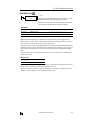
• In this user’s manual, safety precautions are categorized in order of importance to Warning and Caution:
Warning
Warning notices are used to emphasize that improper operation may cause
severe personal injury or death.
• Turn off the power to the OpenNet Controller before starting installation, removal, wiring, maintenance, and inspection of
the OpenNet Controller. Failure to turn power off may cause electrical shocks or fire hazard.
• Special expertise is required to install, wire, program, and operate the OpenNet Controller. People without such expertise
must not use the OpenNet Controller.
• Emergency stop and interlocking circuits must be configured outside the OpenNet Controller. If such a circuit is configured
inside the OpenNet Controller, failure of the OpenNet Controller may cause disorder of the control system, damage, or
accidents.
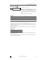
Caution
Caution notices are used where inattention might cause personal injury or
damage to equipment.
• Install the OpenNet Controller according to instructions described in this user’s manual. Improper installation will result in
falling, failure, or malfunction of the OpenNet Controller.
• The OpenNet Controller is designed for installation in a cabinet. Do not install the OpenNet Controller outside a cabinet.
• Install the OpenNet Controller in environments described in this user’s manual. If the OpenNet Controller is used in places
where the OpenNet Controller is subjected to high-temperature, high-humidity, condensation, corrosive gases, excessive
vibrations, and excessive shocks, then electrical shocks, fire hazard, or malfunction will result.
• The environment for using the OpenNet Controller is “Pollution degree 2.” Use the OpenNet Controller in environments of
pollution degree 2 (according to IEC 60664-1).
• The DC power applicable to the OpenNet Controller is “PS2” type (according to EN 61131).
• Prevent the OpenNet Controller from falling while moving or transporting the OpenNet Controller, otherwise damage or
malfunction of the OpenNet Controller will result.
• Prevent metal fragments and pieces of wire from dropping inside the OpenNet Controller housing. Put a cover on the OpenNet Controller modules during installation and wiring. Ingress of such fragments and chips may cause fire hazard, damage,
or malfunction.
• Use a power supply of the rated value. Use of a wrong power supply may cause fire hazard.
• Use wires of a proper size to meet voltage and current requirements. Tighten terminal screws to a proper tightening torque
of 0.5 to 0.6 N·m.
• Use an IEC 60127-approved fuse on the power line outside the OpenNet Controller. This is required when equipment containing the OpenNet Controller is destined for Europe.
• Use an IEC 60127-approved fuse on the output circuit. This is required when equipment containing the OpenNet Controller
is destined for Europe.
• Use an EU-approved circuit breaker. This is required when equipment containing the OpenNet Controller is destined for
Europe.
• Make sure of safety before starting and stopping the OpenNet Controller or when operating the OpenNet Controller to force
outputs on or off. Incorrect operation on the OpenNet Controller may cause machine damage or accidents.
• If relays or transistors in the OpenNet Controller output modules should fail, outputs may remain on or off. For output signals which may cause heavy accidents, provide a monitor circuit outside the OpenNet Controller.
• Do not connect to the ground directly from the OpenNet Controller. Connect a protective ground to the cabinet containing
OpenNet Controller using an M4 or larger screw. This is required when equipment containing the OpenNet Controller is
destined for Europe.
• Do not disassemble, repair, or modify the OpenNet Controller modules.
• Dispose of the battery in the OpenNet Controller modules when the battery is dead in accordance with pertaining regulations. When storing or disposing of the battery, use a proper container prepared for this purpose. This is required when
equipment containing the OpenNet Controller is destined for Europe.
• When disposing of the OpenNet Controller, do so as an industrial waste.
OPENNET CONTROLLER USER’S MANUAL
PREFACE-1
About This Manual
This user’s manual primarily describes entire functions of the OpenNet Controller CPU modules, digital I/O modules, analog I/O modules. Also included are powerful communications of the OpenNet Controller.
CHAPTER 1: GENERAL INFORMATION
General information about the OpenNet Controller, features, brief description on special functions, and various system
setup configurations for communication.
CHAPTER 2: MODULE SPECIFICATIONS
Specifications of CPU, digital and analog I/O, expansion power supply, remote I/O master, OpenNet interface modules.
CHAPTER 3: INSTALLATION AND WIRING
Methods and precautions for installing and wiring OpenNet Controller modules.
CHAPTER 4: OPERATION BASICS
General information about setting up the basic OpenNet Controller system for programming, starting and stopping OpenNet Controller operation, and simple operating procedures from creating a user program using WindLDR on a PC to monitoring the OpenNet Controller operation.
CHAPTER 5: SPECIAL FUNCTIONS
Stop/reset inputs, run/stop selection at memory backup error, keep designation for internal relays, shift registers, counters,
and data registers. Also included are module ID selection and run/stop operation upon disparity, input filter, catch input,
high-speed counter, key matrix input, and user program read/write protection.
CHAPTER 6: ALLOCATION NUMBERS
Allocation numbers available for the OpenNet Controller CPU module to program basic and advanced instructions. Special internal relays and special data registers are also described.
CHAPTER 7: BASIC INSTRUCTIONS
Programming of the basic instructions, available operands, and sample programs.
CHAPTER 8: ADVANCED INSTRUCTIONS
General rules of using advanced instructions, terms, data types, and formats used for advanced instructions.
CHAPTER 9 THROUGH CHAPTER 20:
Detailed descriptions on advanced instructions grouped into 12 chapters.
CHAPTER 21 THROUGH CHAPTER 26:
Various communication functions such as data link, computer link, modem mode, remote I/O system, Devicenet slave
module, and LONWORKS interface module.
CHAPTER 27: TROUBLESHOOTING
Procedures to determine the cause of trouble and actions to be taken when any trouble occurs while operating the OpenNet
Controller.
APPENDIX
Additional information about execution times for instructions, I/O delay time, and OpenNet Controller type list.
INDEX
Alphabetical listing of key words.
IMPORTANT INFORMATION
Under no circumstances shall IDEC Corporation be held liable or responsible for indirect or consequential damages resulting
from the use of or the application of IDEC PLC components, individually or in combination with other equipment.
All persons using these components must be willing to accept responsibility for choosing the correct component to suit their application and for choosing an application appropriate for the component, individually or in combination with other equipment.
All diagrams and examples in this manual are for illustrative purposes only. In no way does including these diagrams and
examples in this manual constitute a guarantee as to their suitability for any specific application. To test and approve all programs, prior to installation, is the responsibility of the end user.
PREFACE-2
OPENNET CONTROLLER USER’S MANUAL
TABLE OF CONTENTS
CHAPTER 1:
GENERAL INFORMATION
About the OpenNet Controller . . . . . . . . . . . . . . . . . . . . . . . . . . . . . . . . . . . . . . . . . . .
Features . . . . . . . . . . . . . . . . . . . . . . . . . . . . . . . . . . . . . . . . . . . . . . . . . . . . . . . . . .
Special Functions . . . . . . . . . . . . . . . . . . . . . . . . . . . . . . . . . . . . . . . . . . . . . . . . . . . .
System Setup . . . . . . . . . . . . . . . . . . . . . . . . . . . . . . . . . . . . . . . . . . . . . . . . . . . . . .
CHAPTER 2:
1-1
1-1
1-2
1-3
MODULE SPECIFICATIONS
CPU Module . . . . . . . . . . . . . . . . . . . . . . . . . . . . . . . . . . . . . . . . . . . . . . . . . . . . . . . . 2-1
Input Module . . . . . . . . . . . . . . . . . . . . . . . . . . . . . . . . . . . . . . . . . . . . . . . . . . . . . . . 2-7
Output Module . . . . . . . . . . . . . . . . . . . . . . . . . . . . . . . . . . . . . . . . . . . . . . . . . . . . . 2-16
Analog Input Module (A/D Converter) . . . . . . . . . . . . . . . . . . . . . . . . . . . . . . . . . . . . . 2-28
Analog Output Module (D/A Converter) . . . . . . . . . . . . . . . . . . . . . . . . . . . . . . . . . . . . 2-31
Expansion Power Supply Module . . . . . . . . . . . . . . . . . . . . . . . . . . . . . . . . . . . . . . . . 2-34
Remote I/O Master Module . . . . . . . . . . . . . . . . . . . . . . . . . . . . . . . . . . . . . . . . . . . . 2-36
DeviceNet Slave Module . . . . . . . . . . . . . . . . . . . . . . . . . . . . . . . . . . . . . . . . . . . . . . 2-38
LonWorks Interface Module . . . . . . . . . . . . . . . . . . . . . . . . . . . . . . . . . . . . . . . . . . . . 2-39
Dimensions . . . . . . . . . . . . . . . . . . . . . . . . . . . . . . . . . . . . . . . . . . . . . . . . . . . . . . . 2-40
CHAPTER 3:
AND WIRING
Installation Location . . . . . . . . . . . . . . . . . . . . . . . . . . . . . . . . . . . . . . . . . . . . . . . . . . 3-1
Assembling Modules . . . . . . . . . . . . . . . . . . . . . . . . . . . . . . . . . . . . . . . . . . . . . . . . . . 3-2
Disassembling Modules . . . . . . . . . . . . . . . . . . . . . . . . . . . . . . . . . . . . . . . . . . . . . . . 3-3
Mounting on DIN Rail . . . . . . . . . . . . . . . . . . . . . . . . . . . . . . . . . . . . . . . . . . . . . . . . . 3-3
Removing from DIN Rail . . . . . . . . . . . . . . . . . . . . . . . . . . . . . . . . . . . . . . . . . . . . . . . 3-3
Installation in Control Panel . . . . . . . . . . . . . . . . . . . . . . . . . . . . . . . . . . . . . . . . . . . . . 3-4
Mounting Direction . . . . . . . . . . . . . . . . . . . . . . . . . . . . . . . . . . . . . . . . . . . . . . . . . . . 3-4
Input Wiring . . . . . . . . . . . . . . . . . . . . . . . . . . . . . . . . . . . . . . . . . . . . . . . . . . . . . . . . 3-5
Output Wiring . . . . . . . . . . . . . . . . . . . . . . . . . . . . . . . . . . . . . . . . . . . . . . . . . . . . . . . 3-6
Data Link Wiring . . . . . . . . . . . . . . . . . . . . . . . . . . . . . . . . . . . . . . . . . . . . . . . . . . . . . 3-7
Analog Input/Output Wiring . . . . . . . . . . . . . . . . . . . . . . . . . . . . . . . . . . . . . . . . . . . . . 3-8
Power Supply . . . . . . . . . . . . . . . . . . . . . . . . . . . . . . . . . . . . . . . . . . . . . . . . . . . . . . . 3-9
Terminal Connection . . . . . . . . . . . . . . . . . . . . . . . . . . . . . . . . . . . . . . . . . . . . . . . . . 3-10
CHAPTER 4:
OPERATION BASICS
INSTALLATION
Connecting OpenNet Controller to PC (1:1 Computer Link System) . . . . . . . . . . . . . . . . . 4-1
Start/Stop Operation . . . . . . . . . . . . . . . . . . . . . . . . . . . . . . . . . . . . . . . . . . . . . . . . . 4-2
Simple Operation . . . . . . . . . . . . . . . . . . . . . . . . . . . . . . . . . . . . . . . . . . . . . . . . . . . . 4-4
CHAPTER 5:
SPECIAL FUNCTIONS
Stop Input and Reset Input . . . . . . . . . . . . . . . . . . . . . . . . . . . . . . . . . . . . . . . . . . . . . 5-1
Run/Stop Selection at Memory Backup Error . . . . . . . . . . . . . . . . . . . . . . . . . . . . . . . . 5-2
Keep Designation for Internal Relays, Shift Registers, Counters, and Data Registers . . . . 5-3
Module ID Selection and Run/Stop Operation upon Disparity . . . . . . . . . . . . . . . . . . . . . 5-5
Input Filter . . . . . . . . . . . . . . . . . . . . . . . . . . . . . . . . . . . . . . . . . . . . . . . . . . . . . . . . . 5-6
Catch Input . . . . . . . . . . . . . . . . . . . . . . . . . . . . . . . . . . . . . . . . . . . . . . . . . . . . . . . . 5-7
High-speed Counter . . . . . . . . . . . . . . . . . . . . . . . . . . . . . . . . . . . . . . . . . . . . . . . . . . 5-9
Key Matrix Input . . . . . . . . . . . . . . . . . . . . . . . . . . . . . . . . . . . . . . . . . . . . . . . . . . . . 5-16
User Program Protection . . . . . . . . . . . . . . . . . . . . . . . . . . . . . . . . . . . . . . . . . . . . . . 5-18
Memory Card . . . . . . . . . . . . . . . . . . . . . . . . . . . . . . . . . . . . . . . . . . . . . . . . . . . . . . 5-19
Constant Scan Time . . . . . . . . . . . . . . . . . . . . . . . . . . . . . . . . . . . . . . . . . . . . . . . . . 5-20
OPENNET CONTROLLER USER’S MANUAL
i
TABLE
OF
CONTENTS
CHAPTER 6:
ALLOCATION NUMBERS
Operand Allocation Numbers . . . . . . . . . . . . . . . . . . . . . . . . . . . . . . . . . . . . . . . . . . . . 6-2
Operand Allocation Numbers for Functional Modules . . . . . . . . . . . . . . . . . . . . . . . . . . . 6-4
Operand Allocation Numbers for Master Module . . . . . . . . . . . . . . . . . . . . . . . . . . . . . . 6-4
Operand Allocation Numbers for Data Link Master Station . . . . . . . . . . . . . . . . . . . . . . . 6-5
Operand Allocation Numbers for Data Link Slave Station . . . . . . . . . . . . . . . . . . . . . . . . 6-5
Special Internal Relay Allocation Numbers . . . . . . . . . . . . . . . . . . . . . . . . . . . . . . . . . . . 6-6
Special Data Registers . . . . . . . . . . . . . . . . . . . . . . . . . . . . . . . . . . . . . . . . . . . . . . . 6-12
Digital I/O Module Operands . . . . . . . . . . . . . . . . . . . . . . . . . . . . . . . . . . . . . . . . . . . 6-18
Functional Module Operands . . . . . . . . . . . . . . . . . . . . . . . . . . . . . . . . . . . . . . . . . . . 6-18
Bit Designation of Link Register . . . . . . . . . . . . . . . . . . . . . . . . . . . . . . . . . . . . . . . . . 6-19
CHAPTER 7:
BASIC INSTRUCTIONS
Basic Instruction List . . . . . . . . . . . . . . . . . . . . . . . . . . . . . . . . . . . . . . . . . . . . . . . . . . 7-1
LOD (Load) and LODN (Load Not) . . . . . . . . . . . . . . . . . . . . . . . . . . . . . . . . . . . . . . . . . 7-2
OUT (Output) and OUTN (Output Not) . . . . . . . . . . . . . . . . . . . . . . . . . . . . . . . . . . . . . . . 7-2
SET and RST (Reset) . . . . . . . . . . . . . . . . . . . . . . . . . . . . . . . . . . . . . . . . . . . . . . . . . . 7-3
AND and ANDN (And Not) . . . . . . . . . . . . . . . . . . . . . . . . . . . . . . . . . . . . . . . . . . . . . . . 7-4
OR and ORN (Or Not) . . . . . . . . . . . . . . . . . . . . . . . . . . . . . . . . . . . . . . . . . . . . . . . . . . 7-4
AND LOD (Load) . . . . . . . . . . . . . . . . . . . . . . . . . . . . . . . . . . . . . . . . . . . . . . . . . . . . . 7-5
OR LOD (Load) . . . . . . . . . . . . . . . . . . . . . . . . . . . . . . . . . . . . . . . . . . . . . . . . . . . . . . 7-5
BPS (Bit Push), BRD (Bit Read), and BPP (Bit Pop) . . . . . . . . . . . . . . . . . . . . . . . . . . . . . 7-6
TML, TIM, TMH, and TMS (Timer) . . . . . . . . . . . . . . . . . . . . . . . . . . . . . . . . . . . . . . . . . 7-8
CNT, CDP, and CUD (Counter) . . . . . . . . . . . . . . . . . . . . . . . . . . . . . . . . . . . . . . . . . . 7-11
CC= and CC≥ (Counter Comparison) . . . . . . . . . . . . . . . . . . . . . . . . . . . . . . . . . . . . . . 7-14
TC= and TC≥ (Timer Comparison) . . . . . . . . . . . . . . . . . . . . . . . . . . . . . . . . . . . . . . . . 7-16
DC= and DC≥ (Data Register Comparison) . . . . . . . . . . . . . . . . . . . . . . . . . . . . . . . . . . 7-18
SFR and SFRN (Forward and Reverse Shift Register) . . . . . . . . . . . . . . . . . . . . . . . . . . 7-20
SOTU and SOTD (Single Output Up and Down) . . . . . . . . . . . . . . . . . . . . . . . . . . . . . . . 7-24
MCS and MCR (Master Control Set and Reset) . . . . . . . . . . . . . . . . . . . . . . . . . . . . . . 7-25
JMP (Jump) and JEND (Jump End) . . . . . . . . . . . . . . . . . . . . . . . . . . . . . . . . . . . . . . . . 7-27
END . . . . . . . . . . . . . . . . . . . . . . . . . . . . . . . . . . . . . . . . . . . . . . . . . . . . . . . . . . . . . 7-28
CHAPTER 8:
ADVANCED INSTRUCTIONS
Advanced Instruction List . . . . . . . . . . . . . . . . . . . . . . . . . . . . . . . . . . . . . . . . . . . . . . .
Structure of an Advanced Instruction . . . . . . . . . . . . . . . . . . . . . . . . . . . . . . . . . . . . . . .
Input Condition for Advanced Instructions . . . . . . . . . . . . . . . . . . . . . . . . . . . . . . . . . . .
Source and Destination Operands . . . . . . . . . . . . . . . . . . . . . . . . . . . . . . . . . . . . . . . .
Using Timer or Counter as Source Operand . . . . . . . . . . . . . . . . . . . . . . . . . . . . . . . . . .
Using Timer or Counter as Destination Operand . . . . . . . . . . . . . . . . . . . . . . . . . . . . . . .
Data Types for Advanced Instructions . . . . . . . . . . . . . . . . . . . . . . . . . . . . . . . . . . . . . .
Discontinuity of Operand Areas . . . . . . . . . . . . . . . . . . . . . . . . . . . . . . . . . . . . . . . . . . .
NOP (No Operation) . . . . . . . . . . . . . . . . . . . . . . . . . . . . . . . . . . . . . . . . . . . . . . . . . . .
CHAPTER 9:
8-1
8-3
8-3
8-3
8-3
8-3
8-4
8-5
8-6
MOVE INSTRUCTIONS
MOV (Move) . . . . . . . . . . . . . . . . . . . . . . . . . . . . . . . . . . . . . . . . . . . . . . . . . . . . . . . . 9-1
MOVN (Move Not) . . . . . . . . . . . . . . . . . . . . . . . . . . . . . . . . . . . . . . . . . . . . . . . . . . . . 9-5
IMOV (Indirect Move) . . . . . . . . . . . . . . . . . . . . . . . . . . . . . . . . . . . . . . . . . . . . . . . . . . 9-6
IMOVN (Indirect Move Not) . . . . . . . . . . . . . . . . . . . . . . . . . . . . . . . . . . . . . . . . . . . . . . 9-7
BMOV (Block Move) . . . . . . . . . . . . . . . . . . . . . . . . . . . . . . . . . . . . . . . . . . . . . . . . . . . 9-8
NSET (N Data Set) . . . . . . . . . . . . . . . . . . . . . . . . . . . . . . . . . . . . . . . . . . . . . . . . . . . . 9-9
NRS (N Data Repeat Set) . . . . . . . . . . . . . . . . . . . . . . . . . . . . . . . . . . . . . . . . . . . . . . 9-10
IBMV (Indirect Bit Move) . . . . . . . . . . . . . . . . . . . . . . . . . . . . . . . . . . . . . . . . . . . . . . . 9-11
IBMVN (Indirect Bit Move Not) . . . . . . . . . . . . . . . . . . . . . . . . . . . . . . . . . . . . . . . . . . 9-12
XCHG (Exchange) . . . . . . . . . . . . . . . . . . . . . . . . . . . . . . . . . . . . . . . . . . . . . . . . . . . . 9-13
ii
OPENNET CONTROLLER USER’S MANUAL
TABLE
CHAPTER 10:
OF
CONTENTS
DATA COMPARISON INSTRUCTIONS
CMP= (Compare Equal To) . . . . . . . . . . . . . . . . . . . . . . . . . . . . . . . . . . . . . . . . . . . .
CMP<> (Compare Unequal To) . . . . . . . . . . . . . . . . . . . . . . . . . . . . . . . . . . . . . . . . . .
CMP< (Compare Less Than) . . . . . . . . . . . . . . . . . . . . . . . . . . . . . . . . . . . . . . . . . . .
CMP> (Compare Greater Than) . . . . . . . . . . . . . . . . . . . . . . . . . . . . . . . . . . . . . . . . .
CMP<= (Compare Less Than or Equal To) . . . . . . . . . . . . . . . . . . . . . . . . . . . . . . . . . .
CMP>= (Compare Greater Than or Equal To) . . . . . . . . . . . . . . . . . . . . . . . . . . . . . . . .
ICMP>= (Interval Compare Greater Than or Equal To) . . . . . . . . . . . . . . . . . . . . . . . . .
CHAPTER 11:
10-1
10-1
10-1
10-1
10-1
10-1
10-4
BINARY ARITHMETIC INSTRUCTIONS
ADD (Addition) . . . . . . . . . . . . . . . . . . . . . . . . . . . . . . . . . . . . . . . . . . . . . . . . . . . . . 11-1
SUB (Subtraction) . . . . . . . . . . . . . . . . . . . . . . . . . . . . . . . . . . . . . . . . . . . . . . . . . . . 11-1
MUL (Multiplication) . . . . . . . . . . . . . . . . . . . . . . . . . . . . . . . . . . . . . . . . . . . . . . . . . 11-1
DIV (Division) . . . . . . . . . . . . . . . . . . . . . . . . . . . . . . . . . . . . . . . . . . . . . . . . . . . . . . 11-1
INC (Increment) . . . . . . . . . . . . . . . . . . . . . . . . . . . . . . . . . . . . . . . . . . . . . . . . . . . . 11-9
DEC (Decrement) . . . . . . . . . . . . . . . . . . . . . . . . . . . . . . . . . . . . . . . . . . . . . . . . . . . 11-9
ROOT (Root) . . . . . . . . . . . . . . . . . . . . . . . . . . . . . . . . . . . . . . . . . . . . . . . . . . . . . . 11-10
SUM (Sum) . . . . . . . . . . . . . . . . . . . . . . . . . . . . . . . . . . . . . . . . . . . . . . . . . . . . . . 11-11
CHAPTER 12:
BOOLEAN COMPUTATION INSTRUCTIONS
ANDW (AND Word) . . . . . . . . . . . . . . . . . . . . . . . . . . . . . . . . . . . . . . . . . . . . . . . . . .
ORW (OR Word) . . . . . . . . . . . . . . . . . . . . . . . . . . . . . . . . . . . . . . . . . . . . . . . . . . . .
XORW (Exclusive OR Word) . . . . . . . . . . . . . . . . . . . . . . . . . . . . . . . . . . . . . . . . . . . .
NEG (Negate) . . . . . . . . . . . . . . . . . . . . . . . . . . . . . . . . . . . . . . . . . . . . . . . . . . . . . .
CHAPTER 13:
12-1
12-1
12-1
12-5
BIT SHIFT / ROTATE INSTRUCTIONS
SFTL (Shift Left) . . . . . . . . . . . . . . . . . . . . . . . . . . . . . . . . . . . . . . . . . . . . . . . . . . . . 13-1
SFTR (Shift Right) . . . . . . . . . . . . . . . . . . . . . . . . . . . . . . . . . . . . . . . . . . . . . . . . . . . 13-3
ROTL (Rotate Left) . . . . . . . . . . . . . . . . . . . . . . . . . . . . . . . . . . . . . . . . . . . . . . . . . . 13-5
ROTR (Rotate Right) . . . . . . . . . . . . . . . . . . . . . . . . . . . . . . . . . . . . . . . . . . . . . . . . . 13-7
ROTLC (Rotate Left with Carry) . . . . . . . . . . . . . . . . . . . . . . . . . . . . . . . . . . . . . . . . . . 13-9
ROTRC (Rotate Right with Carry) . . . . . . . . . . . . . . . . . . . . . . . . . . . . . . . . . . . . . . . 13-11
BCDLS (BCD Left Shift) . . . . . . . . . . . . . . . . . . . . . . . . . . . . . . . . . . . . . . . . . . . . . . 13-13
CHAPTER 14:
DATA CONVERSION INSTRUCTIONS
HTOB (Hex to BCD) . . . . . . . . . . . . . . . . . . . . . . . . . . . . . . . . . . . . . . . . . . . . . . . . . . 14-1
BTOH (BCD to Hex) . . . . . . . . . . . . . . . . . . . . . . . . . . . . . . . . . . . . . . . . . . . . . . . . . . 14-3
HTOA (Hex to ASCII) . . . . . . . . . . . . . . . . . . . . . . . . . . . . . . . . . . . . . . . . . . . . . . . . . 14-5
ATOH (ASCII to Hex) . . . . . . . . . . . . . . . . . . . . . . . . . . . . . . . . . . . . . . . . . . . . . . . . . 14-7
BTOA (BCD to ASCII) . . . . . . . . . . . . . . . . . . . . . . . . . . . . . . . . . . . . . . . . . . . . . . . . . 14-9
ATOB (ASCII to BCD) . . . . . . . . . . . . . . . . . . . . . . . . . . . . . . . . . . . . . . . . . . . . . . . . 14-11
DTDV (Data Divide) . . . . . . . . . . . . . . . . . . . . . . . . . . . . . . . . . . . . . . . . . . . . . . . . . 14-13
DTCB (Data Combine) . . . . . . . . . . . . . . . . . . . . . . . . . . . . . . . . . . . . . . . . . . . . . . . 14-14
CHAPTER 15:
WEEK PROGRAMMER INSTRUCTIONS
WKCMP ON (Week Compare ON) . . . . . . . . . . . . . . . . . . . . . . . . . . . . . . . . . . . . . . . .
WKCMP OFF (Week Compare OFF) . . . . . . . . . . . . . . . . . . . . . . . . . . . . . . . . . . . . . . .
WKTBL (Week Table) . . . . . . . . . . . . . . . . . . . . . . . . . . . . . . . . . . . . . . . . . . . . . . . . .
Setting Calendar/Clock Using WindLDR . . . . . . . . . . . . . . . . . . . . . . . . . . . . . . . . . . .
Setting Calendar/Clock Using a User Program . . . . . . . . . . . . . . . . . . . . . . . . . . . . . .
Adjusting Clock Using a User Program . . . . . . . . . . . . . . . . . . . . . . . . . . . . . . . . . . . .
OPENNET CONTROLLER USER’S MANUAL
15-1
15-1
15-2
15-7
15-7
15-8
iii
TABLE
OF
CONTENTS
CHAPTER 16:
INTERFACE INSTRUCTIONS
DISP (Display) . . . . . . . . . . . . . . . . . . . . . . . . . . . . . . . . . . . . . . . . . . . . . . . . . . . . . . 16-1
DGRD (Digital Read) . . . . . . . . . . . . . . . . . . . . . . . . . . . . . . . . . . . . . . . . . . . . . . . . . 16-3
CDISP (Character Display) . . . . . . . . . . . . . . . . . . . . . . . . . . . . . . . . . . . . . . . . . . . . . 16-5
CHAPTER 17:
USER COMMUNICATION INSTRUCTIONS
User Communication Overview . . . . . . . . . . . . . . . . . . . . . . . . . . . . . . . . . . . . . . . . . . 17-1
User Communication System Setup . . . . . . . . . . . . . . . . . . . . . . . . . . . . . . . . . . . . . . 17-2
TXD1 (Transmit 1) . . . . . . . . . . . . . . . . . . . . . . . . . . . . . . . . . . . . . . . . . . . . . . . . . . . 17-4
TXD2 (Transmit 2) . . . . . . . . . . . . . . . . . . . . . . . . . . . . . . . . . . . . . . . . . . . . . . . . . . . 17-4
RXD1 (Receive 1) . . . . . . . . . . . . . . . . . . . . . . . . . . . . . . . . . . . . . . . . . . . . . . . . . . 17-13
RXD2 (Receive 2) . . . . . . . . . . . . . . . . . . . . . . . . . . . . . . . . . . . . . . . . . . . . . . . . . . 17-13
User Communication Error . . . . . . . . . . . . . . . . . . . . . . . . . . . . . . . . . . . . . . . . . . . . 17-25
ASCII Character Code Table . . . . . . . . . . . . . . . . . . . . . . . . . . . . . . . . . . . . . . . . . . . 17-26
RS232C Line Control Signals . . . . . . . . . . . . . . . . . . . . . . . . . . . . . . . . . . . . . . . . . . 17-27
Sample Program – User Communication TXD . . . . . . . . . . . . . . . . . . . . . . . . . . . . . . . 17-31
Sample Program – User Communication RXD . . . . . . . . . . . . . . . . . . . . . . . . . . . . . . . 17-33
CHAPTER 18:
PROGRAM BRANCHING INSTRUCTIONS
LABEL (Label) . . . . . . . . . . . . . . . . . . . . . . . . . . . . . . . . . . . . . . . . . . . . . . . . . . . . . .
LJMP (Label Jump) . . . . . . . . . . . . . . . . . . . . . . . . . . . . . . . . . . . . . . . . . . . . . . . . . . .
LCAL (Label Call) . . . . . . . . . . . . . . . . . . . . . . . . . . . . . . . . . . . . . . . . . . . . . . . . . . . .
LRET (Label Return) . . . . . . . . . . . . . . . . . . . . . . . . . . . . . . . . . . . . . . . . . . . . . . . . . .
DJNZ (Decrement Jump Non-zero) . . . . . . . . . . . . . . . . . . . . . . . . . . . . . . . . . . . . . . . .
CHAPTER 19:
COORDINATE CONVERSION INSTRUCTIONS
XYFS (XY Format Set) . . . . . . . . . . . . . . . . . . . . . . . . . . . . . . . . . . . . . . . . . . . . . . . . .
CVXTY (Convert X to Y) . . . . . . . . . . . . . . . . . . . . . . . . . . . . . . . . . . . . . . . . . . . . . . . .
CVYTX (Convert Y to X) . . . . . . . . . . . . . . . . . . . . . . . . . . . . . . . . . . . . . . . . . . . . . . . .
AVRG (Average) . . . . . . . . . . . . . . . . . . . . . . . . . . . . . . . . . . . . . . . . . . . . . . . . . . . . .
CHAPTER 20:
18-1
18-1
18-3
18-3
18-5
19-1
19-2
19-3
19-6
PID INSTRUCTION
PID (PID Control) . . . . . . . . . . . . . . . . . . . . . . . . . . . . . . . . . . . . . . . . . . . . . . . . . . . . 20-1
Application Example . . . . . . . . . . . . . . . . . . . . . . . . . . . . . . . . . . . . . . . . . . . . . . . . 20-14
CHAPTER 21:
DATA LINK COMMUNICATION
Data Link Specifications . . . . . . . . . . . . . . . . . . . . . . . . . . . . . . . . . . . . . . . . . . . . . . 21-1
Data Link System Setup . . . . . . . . . . . . . . . . . . . . . . . . . . . . . . . . . . . . . . . . . . . . . . . 21-2
Data Register Allocation for Transmit/Receive Data . . . . . . . . . . . . . . . . . . . . . . . . . . . 21-3
Special Data Registers for Data Link Communication Error . . . . . . . . . . . . . . . . . . . . . . 21-4
Data Link Communication between Master and Slave Stations . . . . . . . . . . . . . . . . . . . 21-5
Special Internal Relays for Data Link Communication . . . . . . . . . . . . . . . . . . . . . . . . . . 21-6
Programming WindLDR . . . . . . . . . . . . . . . . . . . . . . . . . . . . . . . . . . . . . . . . . . . . . . . . 21-7
Refresh Modes . . . . . . . . . . . . . . . . . . . . . . . . . . . . . . . . . . . . . . . . . . . . . . . . . . . . . 21-8
Operating Procedure for Data Link System . . . . . . . . . . . . . . . . . . . . . . . . . . . . . . . . . 21-11
Data Link with Other Equipment (Separate Refresh Mode) . . . . . . . . . . . . . . . . . . . . . 21-12
CHAPTER 22:
COMPUTER LINK COMMUNICATION
Computer Link System Setup (1:N Computer Link System) . . . . . . . . . . . . . . . . . . . . . . 22-1
Monitoring PLC Status . . . . . . . . . . . . . . . . . . . . . . . . . . . . . . . . . . . . . . . . . . . . . . . . 22-2
iv
OPENNET CONTROLLER USER’S MANUAL
TABLE
CHAPTER 23:
OF
CONTENTS
MODEM MODE
System Setup . . . . . . . . . . . . . . . . . . . . . . . . . . . . . . . . . . . . . . . . . . . . . . . . . . . . . 23-1
Applicable Modems . . . . . . . . . . . . . . . . . . . . . . . . . . . . . . . . . . . . . . . . . . . . . . . . . 23-2
Internal Relays for Modem Mode . . . . . . . . . . . . . . . . . . . . . . . . . . . . . . . . . . . . . . . . 23-2
Data Registers for Modem Mode . . . . . . . . . . . . . . . . . . . . . . . . . . . . . . . . . . . . . . . . 23-3
Originate Mode . . . . . . . . . . . . . . . . . . . . . . . . . . . . . . . . . . . . . . . . . . . . . . . . . . . . . 23-4
Disconnect Mode . . . . . . . . . . . . . . . . . . . . . . . . . . . . . . . . . . . . . . . . . . . . . . . . . . . 23-6
AT General Command Mode . . . . . . . . . . . . . . . . . . . . . . . . . . . . . . . . . . . . . . . . . . . 23-6
Answer Mode . . . . . . . . . . . . . . . . . . . . . . . . . . . . . . . . . . . . . . . . . . . . . . . . . . . . . . 23-7
Modem Mode Status Data Register . . . . . . . . . . . . . . . . . . . . . . . . . . . . . . . . . . . . . . 23-8
Initialization String Commands . . . . . . . . . . . . . . . . . . . . . . . . . . . . . . . . . . . . . . . . . 23-9
Preparation for Using Modem . . . . . . . . . . . . . . . . . . . . . . . . . . . . . . . . . . . . . . . . . 23-10
Setting Communication Parameters . . . . . . . . . . . . . . . . . . . . . . . . . . . . . . . . . . . . . 23-10
Programming Data Registers and Internal Relays . . . . . . . . . . . . . . . . . . . . . . . . . . . 23-11
Setting Up the CPU Module . . . . . . . . . . . . . . . . . . . . . . . . . . . . . . . . . . . . . . . . . . . 23-11
Operating Procedure . . . . . . . . . . . . . . . . . . . . . . . . . . . . . . . . . . . . . . . . . . . . . . . . 23-11
Sample Program for Modem Originate Mode . . . . . . . . . . . . . . . . . . . . . . . . . . . . . . . 23-12
Sample Program for Modem Answer Mode . . . . . . . . . . . . . . . . . . . . . . . . . . . . . . . . 23-13
Troubleshooting in Modem Communication . . . . . . . . . . . . . . . . . . . . . . . . . . . . . . . 23-14
CHAPTER 24:
REMOTE I/O SYSTEM
Remote I/O System Setup . . . . . . . . . . . . . . . . . . . . . . . . . . . . . . . . . . . . . . . . . . . . 24-1
Specifications . . . . . . . . . . . . . . . . . . . . . . . . . . . . . . . . . . . . . . . . . . . . . . . . . . . . . 24-2
Link Registers for Remote I/O System . . . . . . . . . . . . . . . . . . . . . . . . . . . . . . . . . . . . 24-2
About INTERBUS . . . . . . . . . . . . . . . . . . . . . . . . . . . . . . . . . . . . . . . . . . . . . . . . . . . 24-2
Data Communication between Remote I/O Master and Slave Stations . . . . . . . . . . . . . 24-3
Logical Device Number and Node Number . . . . . . . . . . . . . . . . . . . . . . . . . . . . . . . . . 24-4
Data Mapping . . . . . . . . . . . . . . . . . . . . . . . . . . . . . . . . . . . . . . . . . . . . . . . . . . . . . 24-5
Special Data Registers for Remote I/O Node Information . . . . . . . . . . . . . . . . . . . . . . 24-6
Special Data Registers for INTERBUS Master Information . . . . . . . . . . . . . . . . . . . . . 24-10
Special Internal Relays for INTERBUS Master Information . . . . . . . . . . . . . . . . . . . . . 24-11
Calculation of the INTERBUS Cycle Time . . . . . . . . . . . . . . . . . . . . . . . . . . . . . . . . . . 24-12
Start and Stop of Remote I/O Communication . . . . . . . . . . . . . . . . . . . . . . . . . . . . . 24-12
Function Area Setting for Remote I/O Master Station . . . . . . . . . . . . . . . . . . . . . . . . 24-13
Precautions for Wiring INTERBUS Cable . . . . . . . . . . . . . . . . . . . . . . . . . . . . . . . . . . 24-15
INTERBUS Error Codes . . . . . . . . . . . . . . . . . . . . . . . . . . . . . . . . . . . . . . . . . . . . . . 24-16
CHAPTER 25:
DEVICENET SLAVE MODULE
DeviceNet Slave Module Features . . . . . . . . . . . . . . . . . . . . . . . . . . . . . . . . . . . . . . . 25-1
About DeviceNet . . . . . . . . . . . . . . . . . . . . . . . . . . . . . . . . . . . . . . . . . . . . . . . . . . . . 25-1
DeviceNet Network System Setup . . . . . . . . . . . . . . . . . . . . . . . . . . . . . . . . . . . . . . . 25-2
DeviceNet Slave Module Parts Description . . . . . . . . . . . . . . . . . . . . . . . . . . . . . . . . . 25-3
DeviceNet Slave Module Specifications . . . . . . . . . . . . . . . . . . . . . . . . . . . . . . . . . . . 25-4
Wiring DeviceNet Slave Module . . . . . . . . . . . . . . . . . . . . . . . . . . . . . . . . . . . . . . . . . 25-5
DIP Switch Settings . . . . . . . . . . . . . . . . . . . . . . . . . . . . . . . . . . . . . . . . . . . . . . . . . 25-6
Link Registers for DeviceNet Network Communication . . . . . . . . . . . . . . . . . . . . . . . . . 25-7
Function Area Setting for DeviceNet Slave Station . . . . . . . . . . . . . . . . . . . . . . . . . . . . 25-8
Programming Transmit/Receive Data Using WindLDR . . . . . . . . . . . . . . . . . . . . . . . . . 25-9
Starting Operation . . . . . . . . . . . . . . . . . . . . . . . . . . . . . . . . . . . . . . . . . . . . . . . . . . 25-9
Transmission Time . . . . . . . . . . . . . . . . . . . . . . . . . . . . . . . . . . . . . . . . . . . . . . . . . 25-10
DeviceNet Network Troubleshooting . . . . . . . . . . . . . . . . . . . . . . . . . . . . . . . . . . . . . 25-11
OPENNET CONTROLLER USER’S MANUAL
v
TABLE
OF
CONTENTS
CHAPTER 26:
LONWORKS INTERFACE MODULE
LonWorks Interface Module Features . . . . . . . . . . . . . . . . . . . . . . . . . . . . . . . . . . . . . 26-1
About LON . . . . . . . . . . . . . . . . . . . . . . . . . . . . . . . . . . . . . . . . . . . . . . . . . . . . . . . . 26-1
LonWorks Network Components . . . . . . . . . . . . . . . . . . . . . . . . . . . . . . . . . . . . . . . . . 26-2
LonWorks Network System Setup . . . . . . . . . . . . . . . . . . . . . . . . . . . . . . . . . . . . . . . . 26-3
LonWorks Interface Module Parts Description . . . . . . . . . . . . . . . . . . . . . . . . . . . . . . . 26-4
LonWorks Interface Module Specifications . . . . . . . . . . . . . . . . . . . . . . . . . . . . . . . . . 26-5
Wiring LonWorks Interface Module . . . . . . . . . . . . . . . . . . . . . . . . . . . . . . . . . . . . . . . 26-6
Terminator . . . . . . . . . . . . . . . . . . . . . . . . . . . . . . . . . . . . . . . . . . . . . . . . . . . . . . . . 26-7
Link Registers for LonWorks Network Communication . . . . . . . . . . . . . . . . . . . . . . . . . 26-8
Transmission Time . . . . . . . . . . . . . . . . . . . . . . . . . . . . . . . . . . . . . . . . . . . . . . . . . . 26-9
Function Area Setting for LonWorks Node . . . . . . . . . . . . . . . . . . . . . . . . . . . . . . . . . 26-10
Programming Transmit/Receive Data Using WindLDR . . . . . . . . . . . . . . . . . . . . . . . . . 26-11
Starting Operation . . . . . . . . . . . . . . . . . . . . . . . . . . . . . . . . . . . . . . . . . . . . . . . . . . 26-12
Network Management . . . . . . . . . . . . . . . . . . . . . . . . . . . . . . . . . . . . . . . . . . . . . . . 26-12
Precautions for Modifying Application Program . . . . . . . . . . . . . . . . . . . . . . . . . . . . . . 26-13
LonWorks Interface Module Internal Structure . . . . . . . . . . . . . . . . . . . . . . . . . . . . . . 26-14
Data Exchange between LonWorks Interface Module and CPU Module . . . . . . . . . . . . . 26-16
Application Program Examples . . . . . . . . . . . . . . . . . . . . . . . . . . . . . . . . . . . . . . . . . 26-18
Defined Network Variables . . . . . . . . . . . . . . . . . . . . . . . . . . . . . . . . . . . . . . . . . . . . 26-23
LonWorks Network Troubleshooting . . . . . . . . . . . . . . . . . . . . . . . . . . . . . . . . . . . . . 26-25
CHAPTER 27:
TROUBLESHOOTING
ERROR LED . . . . . . . . . . . . . . . . . . . . . . . . . . . . . . . . . . . . . . . . . . . . . . . . . . . . . . . .
Reading Error Data . . . . . . . . . . . . . . . . . . . . . . . . . . . . . . . . . . . . . . . . . . . . . . . . . .
Special Data Registers for Error Information . . . . . . . . . . . . . . . . . . . . . . . . . . . . . . . .
General Error Codes . . . . . . . . . . . . . . . . . . . . . . . . . . . . . . . . . . . . . . . . . . . . . . . . .
OpenNet Controller Operating Status, Output, and ERROR LED during Errors . . . . . . . . .
Error Causes and Actions . . . . . . . . . . . . . . . . . . . . . . . . . . . . . . . . . . . . . . . . . . . . . .
User Program Execution Error . . . . . . . . . . . . . . . . . . . . . . . . . . . . . . . . . . . . . . . . . . .
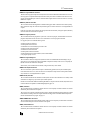
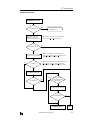
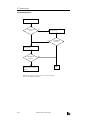
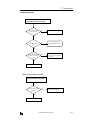
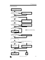
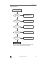
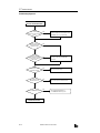
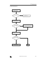
Troubleshooting Diagrams . . . . . . . . . . . . . . . . . . . . . . . . . . . . . . . . . . . . . . . . . . . . .
27-1
27-1
27-3
27-3
27-4
27-4
27-6
27-7
APPENDIX
Execution Times for Instructions . . . . . . . . . . . . . . . . . . . . . . . . . . . . . . . . . . . . . . . . . .
Breakdown of END Processing Time . . . . . . . . . . . . . . . . . . . . . . . . . . . . . . . . . . . . . . .
I/O Delay Time . . . . . . . . . . . . . . . . . . . . . . . . . . . . . . . . . . . . . . . . . . . . . . . . . . . . . .
Type List . . . . . . . . . . . . . . . . . . . . . . . . . . . . . . . . . . . . . . . . . . . . . . . . . . . . . . . . . . .
INDEX
vi
OPENNET CONTROLLER USER’S MANUAL
A-1
A-2
A-2
A-3
1: GENERAL INFORMATION
Introduction
This chapter describes general information for understanding the OpenNet Controller and system setups for using the
OpenNet Controller in various ways of communication.
About the OpenNet Controller
IDEC’s OpenNet Controller is a programmable logic controller with enhanced communication capabilities. The OpenNet
Controller is compatible with world’s three major open networks; INTERBUS, DeviceNet, and LONWORKS. Since application of these networks are expanding at a fast pace, the OpenNet Controller is ideal for use in multi-vendor control systems.
In addition, the OpenNet Controller has user communication functions to communicate with various communication
equipment. Modem communication is also very easy using the built-in modem communication functions to communicate
with remote devices through telephone lines. For these communication applications, the OpenNet Controller CPU module
features two RS232C ports and one RS485 port.
User programs for the OpenNet Controller can be edited using WindLDR on a Windows PC. Since WindLDR can load existing user programs made for IDEC’s preceding PLCs such as all FA series, MICRO-1, MICRO3, and MICRO3C, your software assets can be used in the new control system.
Digital I/O points can be 480 total at the maximum when using an expansion power supply module.
Program capacity is 16K words (8K steps).
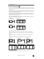
Features
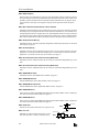
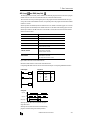
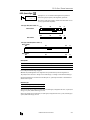
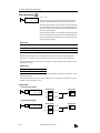
Connect to Open Networks
The OpenNet Controller can be connected to the three major open networks; INTERBUS, DeviceNet, and LONWORKS.
The versatile communication capabilities reduce the time and cost needed when constructing, expanding, or modifying
production lines. Maintenance for communication lines will also become even easier.
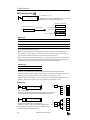
Master Station (Remote I/O)
INTERBUS
Slave Station
DeviceNet, LONWORKS
High-performance CPU Module
The OpenNet Controller CPU module has multiple functions to work as a brain of the control system connected to the
open networks. Optimum control systems can be made possible using the OpenNet Controller.
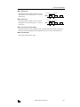
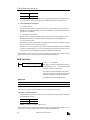
Powerful Communication Functions
In addition to connection to the open networks, the OpenNet Controller features three more communication functions.
User Communication
The OpenNet Controller can be linked to external RS232C devices such as computers,
modems, printers, and barcode readers, using the user communication function.
Data Link
One OpenNet Controller at the master station can communicate with 31 slave stations
through the RS485 line to exchange data and perform distributed control effectively.
Computer Link
When the OpenNet Controller is connected to a computer, operating status and I/O status
can be monitored on the computer, data in the CPU can be monitored or updated, and user
programs can be downloaded and uploaded. A maximum of 32 OpenNet Controller CPUs can
be connected to one computer in the 1:N computer link system.
International Safety Standards and Approvals
The OpenNet Controller is certified by UL and CSA.
OPENNET CONTROLLER USER’S MANUAL
1-1
1: GENERAL INFORMATION
Special Functions
The OpenNet Controller features various special functions packed in the small housing as described below. For details
about these functions, see the following chapters.
“Keep” or “Clear” Designation of CPU Data
Internal relays, shift register bits, counter current values, and data register values can be designated to be kept or cleared
when the CPU is powered down. All of these data or a specified range of these operands can be designated as keep or clear
types.
Catch Input Function
The catch input function makes sure to receive short input pulses (rising pulse of 40 µsec or falling pulse of 150 µsec minimum) from sensors without regard to the scan time.
Input Filter Function
The input filter can be adjusted for the pulse widths to accept or reject input signals. This function is useful for eliminating
input noises and chatter in limit switches.
High-speed Counter Function
The OpenNet Controller has a built-in high-speed counter to make it possible to count up to 65,535 (FFFFh) high-speed
pulses which cannot be counted by the normal user program processing. The maximum count input frequency is 10 kHz.
This function can be used for simple positioning control and simple motor control.
Key Matrix Function
A matrix configuration consisting of 16 inputs and 16 outputs enables to read a maximum of 256 input signals.
User Program Read/Write Protection
The user program in the CPU module can be protected against reading and/or writing by including a password in the user
program. This function is effective for security of user programs.
Week Programmer Function
Week programmer instructions can be programmed to compare the preset date and time with the internal realtime calendar/clock. When the preset values are reached, designated outputs can be turned on and off as programmed for the week.
RUN/STOP Selection at Startup when “Keep” Data is Broken
When data to be kept such as “keep” designated counter values are broken while the CPU is powered down, the user can
select whether the CPU starts to run or not to prevent undesirable operation at the next startup.
Module ID Registration
Another protection method to run or stop operation is the module ID registration. When disparity is found between the
module ID registration and actual modules in the system setup, the CPU can be made to start to run or not.
User Memory Download from Memory Card
A user program can be transferred using WindLDR from a computer to a miniature memory card. The handy miniature card
can be inserted into the CPU module to download the user program. User programs can be replaced without the need for
connecting to a computer. This feature is available on CPU modules FC3A-CP2KM and FC3A-CP2SM.
Constant Scan Time
The scan time may vary whether basic and advanced instructions are executed or not depending on input conditions to
these instructions. When performing repetitive control, the scan time can be made constant by entering a required scan
time value into a special data register reserved for constant scan time.
Keep Output Status during User Program Download
Outputs can be designated to maintain the current statuses when downloading a user program from WindLDR to the CPU.
This function can be used when the output status change does not occur frequently.
Stop and Reset Inputs
Any input number can be designated as a stop or reset input to control the OpenNet Controller operation.
1-2
OPENNET CONTROLLER USER’S MANUAL
1: GENERAL INFORMATION
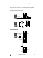
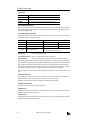
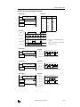
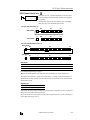
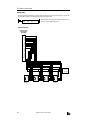
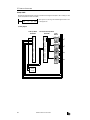
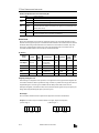
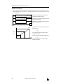
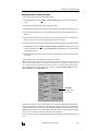
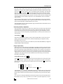
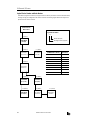
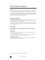
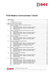
System Setup
This section describes various system setup configurations for using powerful communication functions of the OpenNet
Controller.
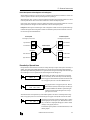
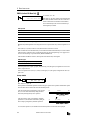
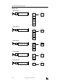
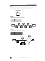
Open Network Communication System
The OpenNet Controller can be connected to three open network communication lines — DeviceNet, LONWORKS, and
INTERBUS.
OpenNet interface modules are available for communication through DeviceNet and LONWORKS networks. The OpenNet
interface modules, such as DeviceNet slave modules and LONWORKS interface modules, serve as a slave station or node in
the network.
A remote I/O system can be set up using a remote I/O master module mounted next to the CPU module and SX5S communication I/O terminals at remote I/O slave stations. When using 32 SX5S modules with 16 input or output points, a total of
512 I/O points can be distributed to 32 remote s lave stations at the maximum. The remote I/O network uses the INTERBUS protocol for communication. The total cable length can be 12.8 km (7.95 miles) maximum.
One remote I/O master module can be mounted with the OpenNet Controller CPU module. In addition, a maximum of
seven functional modules including OpenNet interface modules and analog I/O modules can be mounted with one OpenNet Controller CPU module.
LONWORKS
DeviceNet
POWER
POW
MNS
IO
RUN
ERROR
POW
RUN
ERR
I/O
SER
HSC OUT
NO
H/L
DR1
DR0
NA5
NA4
NA3
NA2
NA1
NA0
COM A
V.24 Interface
RDY/
RUN
FAIL
BSA
PF
HF
SERVICE
REQUEST
B
REMOTE OUT
HSC RS485 +24V 0V
Z OUT
A B G
idec
idec
CPU
Module
0
1
2
3
4
5
6
7
10
11
12
13
14
15
16
17
LON
idec
Remote I/O
Master Module
0
1
2
3
4
5
6
7
10
11
12
13
14
15
16
17
0
1
2
3
4
5
6
7
10
11
12
13
14
15
16
17
OpenNet Interface Modules
I/O Modules
REMOTE IN
REMOTE IN
INTERBUS
UL
RC
BA
ER
RD
SX5S
UL
RC
BA
ER
RD
SX5S
INTERBUS
REMOTE OUT
REMOTE OUT
INTERBUS
Remote I/O
Remote I/O
SX5S Communication I/O Terminals
OPENNET CONTROLLER USER’S MANUAL
1-3
1: GENERAL INFORMATION
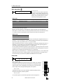
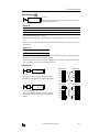
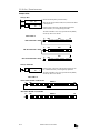
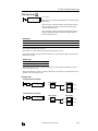
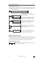
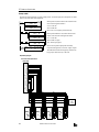
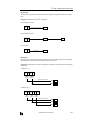
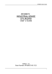
User Communication System
The OpenNet Controller CPU module has two RS232C ports and one RS485 port to control two RS232C devices and one
RS485 device such as IDEC’s HG series operator interface at the same time.
The figure below illustrates a system setup of remote I/O and user communication. In this example, the I/O statuses of a
remote machine are transferred through the remote I/O line to the CPU. The data received through modems is monitored
on a computer and also sent to a pager transmitter.
For details about the remote I/O system, see page 24-1.
For details about the modem mode, see page 23-1.
OpenNet Controller Master Station
Modem
Terminal Block Type
Module Type
Slave Station
Pager Transmitter
Data
Transmission
Data
Communication
Remote Machine
Pager
Modem
Computer
1-4
OPENNET CONTROLLER USER’S MANUAL
1: GENERAL INFORMATION
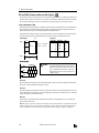
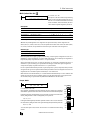
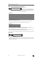
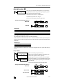
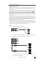
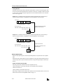
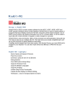
Computer Link System
When the OpenNet Controller is connected to a computer, operating status and I/O status can be monitored on the computer, data in the CPU module can be monitored or updated, and user programs can be downloaded and uploaded. A maximum of 32 OpenNet Controller CPU modules can be connected to one computer in the 1:N computer link system.
For details about the computer link communication, see page 22-1.
Computer Link 1:1 Communication
0
1
2
3
4
5
6
7
8
9
10
11
12
13
14
15
16
17
RS232C Port 1 or Port 2
Computer Link Cable 4C
FC2A-KC4C
3m (9.84 ft.) long
D-sub 9-pin Female Connector
AC Adapter
D-sub 9-pin
Female Connector
0
1
2
3
4
5
6
7
8
9
10
11
12
13
14
15
16
17
RS485
Computer Link Cable 6C
FC2A-KC6C
2m (6.56 ft.) long
Computer Link 1:N Communication
RS232C/RS485 Converter
FC2A-MD1
D-sub 9-pin
Female Connector
RS232C Cable
HD9Z-C52
1.5m (4.92 ft.) long
0
1
2
3
4
5
6
7
8
9
10
11
12
13
14
15
16
17
1st Unit
0
1
2
3
4
5
6
7
8
9
10
11
12
13
14
15
16
17
2nd Unit
Twist-pair Shielded Cable
0
1
2
3
4
5
6
7
8
9
10
11
12
13
14
15
16
17
32nd Unit
RS485
OPENNET CONTROLLER USER’S MANUAL
1-5
1: GENERAL INFORMATION
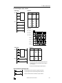
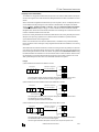
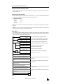
Data Link System
One OpenNet Controller at the master station can communicate with 31 slave stations through the RS485 line to exchange
data and perform distributed control effectively. The RS485 terminals are connected with each other using a 2-core twisted
pair cable.
For details about the data link communication, see page 21-1.
Master Station
Slave Station 1
0
1
2
3
4
5
6
7
8
9
10
11
12
13
14
15
16
17
Slave Station 2
0
1
2
3
4
5
6
7
8
9
10
11
12
13
14
15
16
17
Slave Station 31
HG Series
Operator
Interface
0
1
2
3
4
5
6
7
8
9
10
11
12
13
14
15
16
17
Communication
Selector
DIP Switch
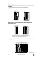
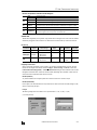
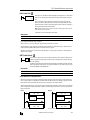
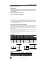
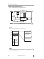
Basic System
The OpenNet Controller CPU module can be mounted with seven modules including digital I/O and functional modules
such as analog I/O, DeviceNet slave, and LONWORKS interface modules to set up a stand alone system. When using seven
digital I/O modules, the I/O points can be 224 points at the maximum.
7 modules (I/O and functional)
CPU Module
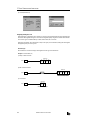
Expansion System
The FC3A-EA1 expansion power supply module is used to mount more than seven I/O and functional modules. When a
maximum of 15 I/O modules are mounted, the number of I/O points is expanded from 224 to 480 maximum.
Whether an expansion power supply module is used or not, seven functional modules such as analog I/O, DeviceNet slave,
and LONWORKS interface modules can be mounted at the maximum in either the normal or expansion slots.
CPU Module
7 modules (I/O and functional)
8 modules (I/O and functional)
Expansion Power Supply Module
A maximum of 7 functional modules can be mounted in any of 15 slots
1-6
OPENNET CONTROLLER USER’S MANUAL
2: MODULE SPECIFICATIONS
Introduction
This chapter describes OpenNet Controller modules, parts names and specifications of each module.
Available modules include CPU modules, digital I/O modules, analog I/O modules, expansion power supply module,
remote I/O master module, and OpenNet interface modules such as DeviceNet slave and LONWORKS interface modules.
Analog I/O modules and OpenNet interface modules are also called functional modules. A maximum of seven functional
modules can be mounted with one CPU module.
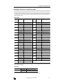
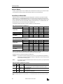
CPU Module
The CPU modules are available in sink and source output types which have a transistor sink or source output of the highspeed counter, respectively. Either type is available with or without a memory card connector. All CPU modules have two
RS232C ports and one RS485 port.
CPU Module Type Numbers
CPU Module Types
Without Memory Card Connector
With Memory Card Connector
High-speed Counter Sink Output Type
FC3A-CP2K
FC3A-CP2KM
High-speed Counter Source Output Type
FC3A-CP2S
FC3A-CP2SM
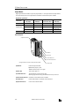
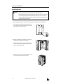
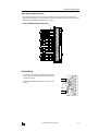
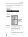
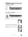
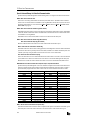
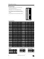
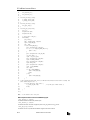
Parts Description
(1) Status LED
6
7
8
(10) Remote I/O
Master Module
Connector
5
(8) Terminal Block
3
4
(2) Communication
Enable Button
(11) End Plate
O
N
1
2
(3) Communication
Selector
DIP Switch
(7) RS232C Port 2
(6) RS232C Port 1
Communication Selector DIP Switch
(5) Memory Card
Eject Button
(9) Expansion Connector
(4) Memory Card Connector
FC3A-CP2KM
FC3A-CP2SM
Opening the Covers
Functions of each part are described on the following pages.
OPENNET CONTROLLER USER’S MANUAL
2-1
2: MODULE SPECIFICATIONS
(1) Status LED
POWER
Turns on when power is supplied to the CPU
RUN
Turns on when the CPU is running
ERROR
Turns on or flashes when an error occurs
HSC OUT
Turns on when the high-speed counter comparison output is on
(2) Communication Enable Button
Enables the communication mode selected with the communication selector DIP switch. When the communication selector DIP switch setting is changed while the CPU is powered up, press this button to enable the new communication mode
for the RS485 and RS232C ports.
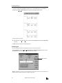
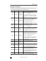
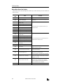
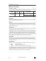
(3) Communication Selector DIP Switch
Selects the communication mode for the RS485 and RS232C ports, and also selects the device number for the CPU in the
computer link or data link communication network.
DIP Switch No.
Function
Setting
1
RS485 port communication mode
ON: Data link mode
OFF: Maintenance mode
2
RS232C port 1 communication mode
ON: User communication mode
OFF: Maintenance mode
3
RS232C port 2 communication mode
ON: User communication mode
OFF: Maintenance mode
Device number selection
Device numbers 0 through 31 for the CPU in the computer
link or data link communication network
4 to 8
Data link mode:
Used for data link communication
User communication mode: Used for user communication or modem communication
Maintenance mode:
Used for computer link communication between the CPU and WindLDR on computer
After changing the settings of the communication selector DIP switch while the CPU is powered up, press the communication enable button for more than 4 seconds until the ERROR LED blinks once; then the new communication mode for the
RS485 or RS232C port takes effect. When the CPU is powered up, the CPU checks the settings of the communication
selector DIP switch and enables the selected communication mode and device number automatically. You have to press the
communication enable button only when you change the DIP switch settings while the CPU is powered up.
Do not power up the CPU while the communication enable button is depressed and do not press the button unless it is necessary.
(4) Memory Card Connector
Plug a miniature memory card into the memory card connector. When a memory card is inserted, the CPU runs the user
program contained in the memory card instead of the user program stored in the CPU memory.
The memory card connector is provided on CPU modules FC3A-CP2KM and FC3A-CP2SM.
(5) Memory Card Eject Button
Press this button to eject the memory card from the CPU module.
(6) RS232C Port 1
Communication port used for the maintenance and user communication modes. User communication instructions TXD1
and RXD1 send and receive data through this port.
(7) RS232C Port 2
Communication port used for the maintenance and user communication modes. User communication instructions TXD2
and RXD2 send and receive data through this port.
2-2
OPENNET CONTROLLER USER’S MANUAL
2: MODULE SPECIFICATIONS
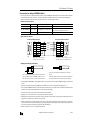
(8) Terminal Block
Function
High-speed Counter
Terminals
RS485 Port
Power Supply Terminals
Terminal No.
Symbol
1
COM
2
A
High-speed counter phase A
3
B
High-speed counter phase B
4
Z
High-speed counter phase Z
5
HSC OUT
High-speed counter comparison output
6
RS485 A
RS485 line A
7
RS485 B
RS485 line B
RS485 line SG
8
RS485 G
9
+24V
10
0V
11
Assignment
High-speed counter COM
Power supply +24V DC
Power supply 0V DC
Frame ground
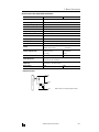
(9) Expansion Connector
For connecting a digital I/O module or functional module.
(10) Remote I/O Master Module Connector
For connecting a remote I/O master module compatible with INTERBUS. This connector is located on the left side of the
CPU module and usually covered with an end plate. When connecting a remote I/O master module, remove the end plate
from the CPU module and attach the remote I/O master module.
(11) End Plate
A pair of end plates are supplied with the CPU module. Remove the end plate from the CPU module before connecting
digital I/O and functional modules, then attach the end plates on both sides of the assembly. For removing the end plates,
see page 3-3.
OPENNET CONTROLLER USER’S MANUAL
2-3
2: MODULE SPECIFICATIONS
General Specifications
Normal Operating Conditions
Operating Temperature
0 to 55°C (operating ambient temperature)
Storage Temperature
–25 to +70°C
Relative Humidity
Level RH1, 30 to 95% (non-condensing)
Pollution Degree
2 (IEC 60664-1)
Corrosion Immunity
Free from corrosive gases
Altitude
Operation: 0 to 2,000m (0 to 6,565 feet)
Transport: 0 to 3,000m (0 to 9,840 feet)
Vibration Resistance
10 to 57 Hz amplitude 0.075 mm, 57 to 150 Hz acceleration 9.8 m/sec2 (1G)
10 sweep cycles per axis on each of three mutually perpendicular axes
(total 80 minutes each) (IEC1131)
Shock Resistance
147 m/sec2 (15G), 11 msec duration, 3 shocks per axis, on three mutually perpendicular axes (IEC1131)
Weight (approx.)
FC3A-CP2K/CP2S (w/o memory card connector):
290g
FC3A-CP2KM/CP2SM (w/memory card connector): 300g
Power Supply
Rated Power Voltage
24V DC
Allowable Voltage Range
19 to 30V DC (including ripple)
Dielectric Strength
Between power terminal and FG:
Between I/O terminal and FG:
Maximum Input Current
1.5A at 24V DC
Power Consumption
500V AC, 1 minute
1,500V AC, 1 minute
8.4W (24V):
CPU module + 48 I/Os (32-DC input module + 16-relay output module)
18W (24V):
CPU module + 128 I/Os (32-DC input module × 2 + 16-DC input module + 16-relay output module × 3)
11.8W (24V): CPU module + remote I/O master module + 48 I/Os (32-DC input module + 16-relay output module)
21.4W (24V): CPU module + remote I/O master module + 128 I/Os (32-DC input
module × 2 + 16-DC input module + 16-relay output module × 3)
2-4
Allowable Momentary Power
Interruption
10 msec (24V DC), Level PS-2 (EN61131)
Insulation Resistance
Between power terminal and FG: 10 MΩ minimum (500V DC megger)
Between I/O terminal and FG:
10 MΩ minimum (500V DC megger)
Inrush Current
40A maximum (24V DC)
Ground
Grounding resistance: 100Ω maximum
Grounding Wire
UL1015 AWG22, UL1007 AWG18
Power Supply Wire
UL1015 AWG22, UL1007 AWG18
Effect of Improper Power
Supply Connection
Reverse polarity:
Improper voltage or frequency:
Improper lead connection:
No operation, no damage
Permanent damage may be caused
Permanent damage may be caused
OPENNET CONTROLLER USER’S MANUAL
2: MODULE SPECIFICATIONS
Function Specifications
CPU Module Specifications
Program Capacity
I/O
Quantity of Slots
7 slots maximum (without using expansion power supply module)
15 slots maximum (when using expansion power supply module)
Maximum Digital
I/O Points
224 points (without using expansion power supply module)
480 points (when using expansion power supply module)
• 56 points when using 7 modules of 8-point I/O
• 112 points when using 7 modules of 16-point I/O
• 224 points when using 7 modules of 32-point I/O
• 480 points when using 15 modules of 32-point I/O
User Program Memory
RAM
Backup
16K words (8K steps)
Flash ROM, RAM, memory card
Backup Duration
Approx. 30 days (typical) at 25°C after backup battery fully charged
Backup Data
Internal relay, shift register, counter, data register
Battery
Lithium secondary battery
Charging Speed
Approx. 2 hours from 0% to 90% of full charge
Battery Life
Approx. 10 years using in cycles of 9-hour charging, 15-hour discharging
Replaceability
Impossible
Control System
Stored program system (not in compliance with EN61131-3)
Instruction Words
37 basic instructions
65 advanced instructions
Processing Time
Basic/advanced instruction: See page A-1.
END processing: See page A-2.
Clock/calendar processing: One cycle in 100 msec (see page A-2)
Data link master station processing: See pages page 21-1 and page 21-10.
Internal Relay
2,048 points
Data Register
8,000 points
Counter
256 points (adding, dual pulse reversible, up/down selection reversible)
Timer
256 points (1-sec, 100-msec, 10-msec, 1-msec)
Catch Input
First 8 channels of each input module can be designated as catch inputs
Minimum turn on pulse width: 40 µsec maximum
Minimum turn off pulse width: 150 µsec maximum
Calendar/Clock
Accuracy: ±30 sec/month at 25°C (typical)
Backup duration: Approx. 30 days 25°C (typical)
Self-diagnostic Function
Keep data sum check, WDT check, user program RAM sum check, user program ROM
sum check, user program write check, power failure check, timer/counter preset
value sum check, calendar/clock error check, user program syntax check, data link
connection check, I/O bus check, I/O bus initialization check, user program execution
check
Start/Stop Method
Turning power on and off
Start/stop command in WindLDR
Turning start control special internal relay M8000 on and off
Turning designated stop or reset input off and on
OPENNET CONTROLLER USER’S MANUAL
2-5
2: MODULE SPECIFICATIONS
System Statuses at Stop, Reset, and Restart
Mode
Internal Relays, Shift Registers,
Counters, Data Registers
Outputs
Keep Type
Run
Operating
Clear Type
Operating
Operating
Timer
Current Value
Operating
Link Register
(Note)
Operating
Reset (Reset input ON)
OFF
OFF/Reset to zero
OFF/Reset to zero
Reset to zero
Reset to zero
Stop (Stop input ON)
OFF
Unchanged
Unchanged
Unchanged
Unchanged
Restart
Unchanged
Unchanged
OFF/Reset to zero
Reset to preset
Unchanged
Note: Link registers used as outputs are turned off like outputs.
Communication Function
Communication Port
RS232C Port 1
RS232C Port 2
RS485 Port
Standards
EIA RS232C
EIA RS232C
EIA RS485
Baud Rate
19,200 bps
19,200 bps
Computer link: 19,200 bps
Data link: 38,400 bps
Maintenance Communication
Possible
Possible
Possible
User Communication
Possible
Possible
Impossible
Data Link Communication
Impossible
Impossible
Possible
Quantity of Slave Stations
—
—
31
Maximum Cable Length
Special cable
Special cable
200m *
Isolation between Power Supply and
Communication Port
Not isolated
Not isolated
Not isolated
* Recommended cable for data link: Twisted-pair shielded cable with a minimum core wire diameter of 0.9 mm.
Conductor resistance 85 Ω/km maximum, shield resistance 20 Ω/km maximum.
Communication Selector DIP Switch Settings
DIP Switch No.
Function
Setting
1
RS485 port communication mode
ON: Data link mode
OFF: Maintenance mode
2
RS232C port 1 communication mode
ON: User communication mode
OFF: Maintenance mode
3
RS232C port 2 communication mode
ON: User communication mode
OFF: Maintenance mode
Device number selection
Device numbers 0 through 31 for the CPU
4 to 8
Memory Card
Card Type
Miniature memory card
Accessible Memory Capacity
2MB, 5V type
Download Destination
CPU module (FC3A-CP2KM and -CP2SM)
Software for Writing Card
WindLDR
Quantity of Stored Programs
One user program stored on one memory card
Program Execution Priority
When a memory card is inserted, user program on the memory card is executed.
High-speed Counter
2-6
Maximum Counting Frequency
10 kHz
Counting Range
0 to 65535 (16 bits)
Operation Mode
Rotary encoder mode
Dual-pulse reversible counter mode
Comparison Output
Transistor sink or source output 1 point (500mA)
Output delay: 20 µsec
OPENNET CONTROLLER USER’S MANUAL
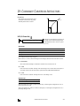
2: MODULE SPECIFICATIONS
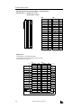
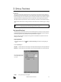
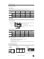
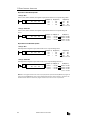
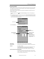
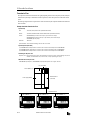
Input Module
Digital input modules are available in 16- and 32-point DC input modules and 8-point AC input modules. Four different
connector/terminal styles are available.
Input Module Type Numbers
Module Name
Screw Terminal
Nylon Connector
16-point DC Input
32-point DC Input
8-point AC Input
FC3A-N16B1
—
FC3A-N08A11
FC3A-N16B3
—
—
—
FC3A-N32B4
—
—
FC3A-N32B5
—
Fujitsu Connector
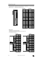
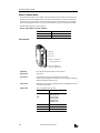
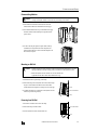
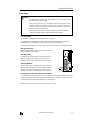
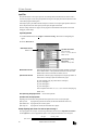
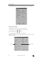
Parts Description
(6) Expansion Connector
(1) Module ID
(2) Status LED
(3) Terminal Block Cover
(4) Cable Terminal/Connector
This figure illustrates a screw terminal type input module.
(1) Module ID
(5) Terminal Label
Indicates the input module ID.
DC IN:
AC IN:
24V DC sink/source input, 16 or 32 points
100V AC input, 8 points
(2) Status LED
Turns on when input is on.
(3) Terminal Block Cover
The terminal block cover flips open to the right.
When using long ferrules for wiring, the terminal block cover may be removed.
(4) Cable Terminal/Connector
Five different terminal/connector styles are available for wiring.
(5) Terminal Label
Indicates terminal numbers 1 through 20 on the terminal block.
(6) Expansion Connector
Connects to CPU and other modules.
OPENNET CONTROLLER USER’S MANUAL
2-7
2: MODULE SPECIFICATIONS
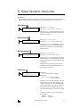
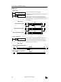
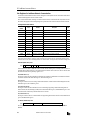
16-point DC Input Module Specifications
Type No.
FC3A-N16B1
FC3A-N16B3
Rated Input Voltage
24V DC sink/source input signal
Input Voltage Range
19 to 30V DC
Rated Input Current
7 mA/point (24V DC)
Terminal Arrangement
See Terminal Arrangement charts on pages 2-11 and 2-12.
Input Impedance
3.4 kΩ
Turn ON Time (24V DC)
20 µsec + filter preset
Turn OFF Time (24V DC)
120 µsec + filter preset
Input Filter
0 msec, 0.5 msec, 1 msec, 2 msec, 4 msec, 8 msec, 16 msec, 32 msec
Isolation
Between input terminals:
Internal circuit:
External Load for I/O Interconnection
Not needed
Signal Determination Method
Static
Effect of Improper Input Connection
Both sinking and sourcing input signals can be connected. If any input
exceeding the rated value is applied, permanent damage may be caused.
Cable Length
3m (9.84 ft.) in compliance with electromagnetic immunity
Connector on Mother Board
Screw Terminal Block
MSTBA2.5/20-G5.08
(Phoenix Contact)
Nylon Connector
B10PS-VH × 2
(J.S.T. Mfg.)
Connector Insertion/Removal Durability
100 times minimum
50 times minimum
Internal Current Draw
All inputs ON:
All inputs OFF:
Weight (approx.)
210g
Not isolated
Photocoupler isolated
40 mA (24V DC)
10 mA (24V DC)
180g
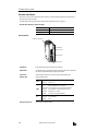
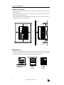
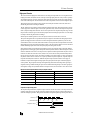
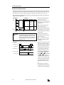
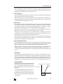
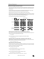
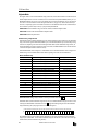
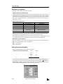
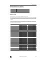
Input Operating Range
The input operating range of the Type 1 (EN61131) input module is shown below:
Input Voltage (V DC)
30
ON Area
24
15
Transition
Area
OFF Area
5
0
4.4
7
1.5
Input Current (mA)
8.8
3.3 kΩ
COM
Input
2-8
Internal Circuit
Input Internal Circuit
OPENNET CONTROLLER USER’S MANUAL
2: MODULE SPECIFICATIONS
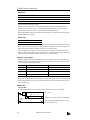
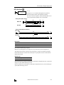
32-point DC Input Module Specifications
Type No.
FC3A-N32B4
FC3A-N32B5
Rated Input Voltage
24V DC sink/source input signal
Input Voltage Range
20.4 to 27.6V DC
Rated Input Current
4.9 mA/point (24V DC)
Terminal Arrangement
See Terminal Arrangement charts on pages 2-13 and 2-14.
Input Impedance
4.7 kΩ
Turn ON Time (24V DC)
20 µsec + filter preset
Turn OFF Time (24V DC)
120 µsec + filter preset
Input Filter
0 msec, 0.5 msec, 1 msec, 2 msec, 4 msec, 8 msec, 16 msec, 32 msec
Isolation
Between input terminals:
Internal circuit:
External Load for I/O Interconnection
Not needed
Signal Determination Method
Static
Effect of Improper Input Connection
Both sinking and sourcing input signals can be connected. If any input
exceeding the rated value is applied, permanent damage may be caused.
Cable Length
3m (9.84 ft.) in compliance with electromagnetic immunity
Connector on Mother Board
Nylon Connector
BS18P-SHF-1AA × 2
(J.S.T. Mfg.)
Fujitsu Connector
FCN-365P040-AU
(Fujitsu)
Connector Insertion/Removal Durability
50 times minimum
500 times minimum
Internal Current Draw
All inputs ON:
All inputs OFF:
Allowable Simultaneous ON Inputs
70% maximum
Weight (approx.)
230g
Not isolated
Photocoupler isolated
50 mA (24V DC)
10 mA (24V DC)
240g
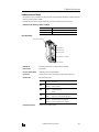
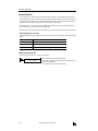
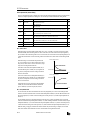
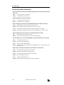
Input Operating Range
The input operating range of the Type 1 (EN61131) input module is shown below:
Input Voltage (V DC)
27.6
24
ON Area
15
Transition
Area
5
OFF Area
0
1
4.4
5.4
4.9
Input Current (mA)
4.7 kΩ
COM
Input
Internal Circuit
Input Internal Circuit
OPENNET CONTROLLER USER’S MANUAL
2-9
2: MODULE SPECIFICATIONS
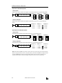
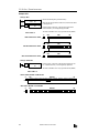
8-point AC Input Module Specifications
Type No.
FC3A-N08A11
Rated Input Voltage
100 to 120V AC
Input Voltage Range
85 to 132V AC
Rated Input Current
8.3 mA/point (100V AC, 60 Hz)
Terminal Arrangement
See Terminal Arrangement chart on page 2-15.
Input Impedance
12 kΩ (60 Hz)
Turn ON Time (100V AC)
20 msec maximum
Turn OFF Time (100V AC)
20 msec maximum
Isolation
Between input terminals:
Internal circuit:
External Load for I/O Interconnection
Not needed
Signal Determination Method
Static
Effect of Improper Input Connection
If any input exceeding the rated value is applied, permanent damage may
be caused.
Cable Length
3m (9.84 ft.) in compliance with electromagnetic immunity
Connector on Mother Board
Screw Terminal Block
MSTBA2.5/20-G5.08
(Phoenix Contact)
Connector Insertion/Removal Durability
100 times minimum
Internal Current Draw
All inputs ON:
All inputs OFF:
Weight (approx.)
220g
Not isolated
Photocoupler isolated
30 mA (24V DC)
20 mA (24V DC)
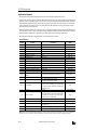
Input Operating Range
The input operating range of the Type 1 (EN61131) input module is shown below:
Input Voltage (V AC)
132
ON Area
100
79
Transition
Area
OFF Area
20
0
6.5 8.3
1.6
Input Current (mA)
11
Internal Circuit
Input Internal Circuit
COM
Input
2-10
OPENNET CONTROLLER USER’S MANUAL
2: MODULE SPECIFICATIONS
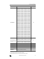
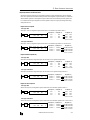
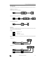
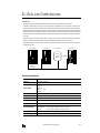
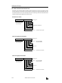
Input Module Terminal Arrangement
FC3A-N16B1 (16-point DC Input Module) — Screw Terminal Type
Applicable Connector:
SMSTB2.5/20-ST-5.08 (Phoenix Contact)
Terminal No.
1
2
3
4
5
6
7
8
9
10
11
12
13
14
15
16
17
18
19
20
DC
IN
0
1
2
3
4
5
6
7
10
11
12
13
14
15
16
17
Name
COM
COM
I0
I1
I2
I3
I4
I5
I6
I7
COM
COM
I10
I11
I12
I13
I14
I15
I16
I17
Wiring Schematic
• COM terminals are connected together internally.
• Terminal numbers are marked on the terminal block label on the input module.
• For wiring precautions, see page 3-5.
Sink Input Wiring
+ –
Source Input Wiring
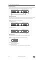
Terminal No.
1
2
3
4
5
6
7
8
9
10
11
12
13
14
15
16
17
18
19
20
Name
COM
COM
I0
I1
I2
I3
I4
I5
I6
I7
COM
COM
I10
I11
I12
I13
I14
I15
I16
I17
– +
OPENNET CONTROLLER USER’S MANUAL
Terminal No.
1
2
3
4
5
6
7
8
9
10
11
12
13
14
15
16
17
18
19
20
Name
COM
COM
I0
I1
I2
I3
I4
I5
I6
I7
COM
COM
I10
I11
I12
I13
I14
I15
I16
I17
2-11
2: MODULE SPECIFICATIONS
FC3A-N16B3 (16-point DC Input Module) — Nylon Connector Type
Applicable Connectors: VHR-10N (J.S.T. Mfg.)
SVH-21T-P1.1 (J.S.T. Mfg.)
CN1
CN1
Terminal No.
1
2
3
4
5
6
7
8
9
10
DC
IN
0
1
2
3
4
5
6
7
10
11
12
13
14
15
16
17
CN2
Name
COM
COM
I0
I1
I2
I3
I4
I5
I6
I7
CN2
Terminal No.
1
2
3
4
5
6
7
8
9
10
Name
COM
COM
I10
I11
I12
I13
I14
I15
I16
I17
Wiring Schematic
• COM terminals are connected together internally.
• Terminal numbers are marked on the female connector on the cable.
• For wiring precautions, see page 3-5.
Sink Input Wiring
+ –
2-12
CN1
Terminal No.
1
2
3
4
5
6
7
8
9
10
Name
COM
COM
I0
I1
I2
I3
I4
I5
I6
I7
CN2
Terminal No.
1
2
3
4
5
6
7
8
9
10
Name
COM
COM
I10
I11
I12
I13
I14
I15
I16
I17
Source Input Wiring
– +
OPENNET CONTROLLER USER’S MANUAL
CN1
Terminal No.
1
2
3
4
5
6
7
8
9
10
Name
COM
COM
I0
I1
I2
I3
I4
I5
I6
I7
CN2
Terminal No.
1
2
3
4
5
6
7
8
9
10
Name
COM
COM
I10
I11
I12
I13
I14
I15
I16
I17
2: MODULE SPECIFICATIONS
FC3A-N32B4 (32-point DC Input Module) — Nylon Connector Type
Applicable Connector:
H18-SHF-AA (J.S.T. Mfg.)
SHF-001T-0.8BS (J.S.T. Mfg.)
CN1
Terminal No.
18
17
16
15
14
13
12
11
10
9
8
7
6
5
4
3
2
1
CN1
DC
IN
CN2
0
1
2
3
4
5
6
7
10
11
12
13
14
15
16
17
20
21
22
23
24
25
26
27
30
31
32
33
34
35
36
37
CN2
Name
I0
I1
I2
I3
I4
I5
I6
I7
I10
I11
I12
I13
I14
I15
I16
I17
COM
COM
Terminal No.
18
17
16
15
14
13
12
11
10
9
8
7
6
5
4
3
2
1
Name
I20
I21
I22
I23
I24
I25
I26
I27
I30
I31
I32
I33
I34
I35
I36
I37
COM
COM
Wiring Schematic
• COM terminals are connected together internally.
• Terminal numbers are marked on the female connector on the cable.
• For wiring precautions, see page 3-5.
+
–
–
+
Sink
Input
Wiring
Source
Input
Wiring
CN1
Terminal No.
18
17
16
15
14
13
12
11
10
9
8
7
6
5
4
3
2
1
Name
I0
I1
I2
I3
I4
I5
I6
I7
I10
I11
I12
I13
I14
I15
I16
I17
COM
COM
CN2
Terminal No.
18
17
16
15
14
13
12
11
10
9
8
7
6
5
4
3
2
1
OPENNET CONTROLLER USER’S MANUAL
Name
I20
I21
I22
I23
I24
I25
I26
I27
I30
I31
I32
I33
I34
I35
I36
I37
COM
COM
2-13
2: MODULE SPECIFICATIONS
FC3A-N32B5 (32-point DC Input Module) — Fujitsu Connector Type
Applicable Connector:
FCN-367J040-AU (Fujitsu)
Terminal No.
B20
B19
B18
B17
B16
B15
B14
B13
B12
B11
B10
B9
B8
B7
B6
B5
B4
B3
B2
B1
DC
IN
0
1
2
3
4
5
6
7
10
11
12
13
14
15
16
17
20
21
22
23
24
25
26
27
30
31
32
33
34
35
36
37
Name
I0
I1
I2
I3
I4
I5
I6
I7
I10
I11
I12
I13
I14
I15
I16
I17
NC
NC
COM
COM
Terminal No.
A20
A19
A18
A17
A16
A15
A14
A13
A12
A11
A10
A9
A8
A7
A6
A5
A4
A3
A2
A1
Name
I20
I21
I22
I23
I24
I25
I26
I27
I30
I31
I32
I33
I34
I35
I36
I37
NC
NC
NC
NC
Wiring Schematic
• COM terminals are connected together internally.
• Terminal numbers are the front view of the male connector on the input module.
• For wiring precautions, see page 3-5.
+
–
Sink
Input
Wiring
2-14
–
+
Terminal No.
B20
B19
B18
B17
B16
B15
B14
B13
B12
B11
B10
B9
B8
B7
B6
B5
B4
B3
B2
B1
Name
I0
I1
I2
I3
I4
I5
I6
I7
I10
I11
I12
I13
I14
I15
I16
I17
NC
NC
COM
COM
Terminal No.
A20
A19
A18
A17
A16
A15
A14
A13
A12
A11
A10
A9
A8
A7
A6
A5
A4
A3
A2
A1
Name
I20
I21
I22
I23
I24
I25
I26
I27
I30
I31
I32
I33
I34
I35
I36
I37
NC
NC
NC
NC
Source
Input
Wiring
OPENNET CONTROLLER USER’S MANUAL
B20
B19
B18
B17
B16
B15
B14
B13
B12
B11
B10
B9
B8
B7
B6
B5
B4
B3
B2
B1
A20
A19
A18
A17
A16
A15
A14
A13
A12
A11
A10
A9
A8
A7
A6
A5
A4
A3
A2
A1
2: MODULE SPECIFICATIONS
FC3A-N08A11 (8-point AC Input Module) — Screw Terminal Type
Applicable Connector:
SMSTB2.5/20-ST-5.08 (Phoenix Contact)
Terminal No.
1
2
3
4
5
6
7
8
9
10
11
12
13
14
15
16
17
18
19
20
AC
IN
0
1
2
3
4
5
6
7
Name
COM0
I0
COM1
I1
COM2
I2
COM3
I3
COM4
I4
COM5
I5
COM6
I6
COM7
I7
NC
NC
NC
NC
Wiring Schematic
• COM terminals are not connected together internally.
• Terminal numbers are marked on the terminal block label on the input module.
• For wiring precautions, see page 3-5.
Terminal No.
1
2
3
4
5
6
7
8
9
10
11
12
13
14
15
16
17
18
19
20
OPENNET CONTROLLER USER’S MANUAL
Name
COM0
I0
COM1
I1
COM2
I2
COM3
I3
COM4
I4
COM5
I5
COM6
I6
COM7
I7
NC
NC
NC
NC
2-15
2: MODULE SPECIFICATIONS
Output Module
Digital output modules are available in 16-point relay output modules, 16- and 32-point transistor sink output modules,
and 16-point transistor protect source output modules. Five different connector/terminal styles are available.
Output Module Type Numbers
Module Name
Screw Terminal
16-point
Relay Output
16-point Transistor
Sink Output
16-point Transistor
Protect Source Output
32-point Transistor
Sink Output
FC3A-R161
FC3A-T16K1
FC3A-T16P1
—
FC3A-R162
—
—
—
—
FC3A-T16K3
—
—
—
—
—
FC3A-T32K4
—
—
—
FC3A-T32K5
Nylon Connector
Fujitsu Connector
Parts Description
(6) Expansion Connector
(1) Module ID
(2) Status LED
(3) Terminal Block Cover
(4) Cable Terminal/Connector
This figure illustrates a screw terminal type output module.
(1) Module ID
(5) Terminal Label
Indicates the output module ID.
Ry OUT: Relay output, 16 points
Tr OUT: Transistor output, 16 or 32 points
(2) Status LED
Turns on when output is on.
(3) Terminal Block Cover
The terminal block cover flips open to the right.
When using long ferrules for wiring, the terminal block cover may be removed.
(4) Cable Terminal/Connector
Six different connector/terminal styles are available
(5) Terminal Label
Indicates terminal numbers 1 through 20 on the terminal block.
(6) Expansion Connector
Connects to CPU and other modules.
2-16
OPENNET CONTROLLER USER’S MANUAL
2: MODULE SPECIFICATIONS
16-point Relay Output Module Specifications
Type No.
FC3A-R161
FC3A-R162
Terminal Arrangement
See Terminal Arrangement charts on pages 2-22 and 2-23.
Output Points and Common Lines
16 NO contacts in 4 common lines (COM terminals not connected together)
2A per point
Maximum Load Current
8A per common line
7A per common line
Minimum Switching Load
0.1 mA/0.1V DC (reference value)
Initial Contact Resistance
30 mΩ maximum
Electrical Life
100,000 operations minimum (rated load 1,800 operations/hour)
Mechanical Life
20,000,000 operations minimum (no load 18,000 operations/hour)
Rated Load Voltage (resistive/inductive)
240V AC/2A, 30V DC/2A
Dielectric Strength
Between output terminal and FG:
1,500V AC, 1 minute
Between output terminal and internal circuit: 1,500V AC, 1 minute
Between output terminals (COMs):
1,500V AC, 1 minute
Connector on Mother Board
Screw Terminal Block
MSTBA2.5/20-G5.08
(Phoenix Contact)
Nylon Connector
B5PS-VH × 4
(J.S.T. Mfg.)
Connector Insertion/Removal Durability
100 times minimum
50 times minimum
Internal Current Draw
All outputs ON: 170 mA (24V DC)
All outputs OFF: 20 mA (24V DC)
Output Delay
Turn ON time:
Chatter:
Turn OFF time:
Weight (approx.)
260g
6 msec maximum
6 msec maximum
10 msec maximum
230g
Contact Protection Circuit for Relay Output
Depending on the load, a protection circuit may be needed for the relay output of the OpenNet Controller. Choose a protection circuit from A through D shown below according to the power supply and connect the protection circuit to the outside
of the relay output module.
Protection Circuit A
Protection Circuit B
Output Q
Inductive Load
Output Q
Inductive Load
C
R
R
COM
COM
or
–
C
+
Protection circuit A can be used when the load impedance is
smaller than the RC impedance in an AC load power circuit.
C: 0.1 to 1 µF
R: Resistor of about the same resistance value as the load
Protection circuit B can be used for both AC and DC load
power circuits.
C: 0.1 to 1 µF
R: Resistor of about the same resistance value as the load
Protection Circuit C
Protection Circuit D
Output Q
Inductive Load
Output Q
Inductive Load
Varistor
COM
– +
– +
COM
or
Protection circuit C can be used for DC load power circuits.
Use a diode with the following ratings.
Reverse withstand voltage: Power voltage of the load circuit × 10
Forward current:
More than the load current
Protection circuit D can be used for both AC and DC load
power circuits.
OPENNET CONTROLLER USER’S MANUAL
2-17
2: MODULE SPECIFICATIONS
16-point Transistor Sink Output Module Specifications
Type No.
FC3A-T16K1
FC3A-T16K3
Terminal Arrangement
See Terminal Arrangement charts on pages 2-24 and 2-25.
Rated Load Voltage
24V DC
Operating Load Voltage Range
19 to 30V DC
Rated Load Current
0.5A per output point
Maximum Load Current
0.625A per output point (at 30V DC)
5A per common line (at 30V DC)
Voltage Drop (ON Voltage)
1V maximum (voltage between COM and output terminals when output is on)
Inrush Current
5A maximum
Leakage Current
0.1 mA maximum
Clamping Voltage
39V±1V
Maximum Lamp Load
10W
Inductive Load
L/R = 10 msec (30V DC, 0.5 Hz)
External Current Draw
100 mA maximum, 24V DC (power voltage at the +V terminal)
Isolation
Between output terminal and internal circuit: Photocoupler isolated
Between output terminals:
Not isolated
Connector on Mother Board
Screw Terminal Block
MSTBA2.5/20-G5.08
(Phoenix Contact)
Nylon Connector
B10PS-VH × 2
(J.S.T. Mfg.)
Connector Insertion/Removal Durability
100 times minimum
50 times minimum
Internal Current Draw
All outputs ON: 60 mA (24V DC)
All outputs OFF: 20 mA (24V DC)
Output Delay
Turn ON time:
Turn OFF time:
Weight (approx.)
220g
500 µsec maximum
500 µsec maximum
190g
Output Internal Circuit
Internal Circuit
+V
Output
COM (–)
2-18
COM terminals are connected together internally.
OPENNET CONTROLLER USER’S MANUAL
2: MODULE SPECIFICATIONS
16-point Transistor Protect Source Output Module Specifications
Type No.
FC3A-T16P1
Terminal Arrangement
See Terminal Arrangement chart on page 2-24.
Rated Load Voltage
24V DC
Operating Load Voltage Range
19 to 30V DC
Rated Load Current
0.5A per output point
Maximum Load Current
0.625A per output point (at 30V DC)
5A per common line (at 30V DC)
Voltage Drop (ON Voltage)
1V maximum (voltage between COM and output terminals when output is on)
Inrush Current
5A maximum
Leakage Current
0.1 mA maximum
Clamping Voltage
39V±1V
Maximum Lamp Load
10W
Inductive Load
L/R = 10 msec (30V DC, 0.5 Hz)
External Current Draw
100 mA maximum, 24V DC (power voltage at the –V terminal)
Isolation
Between output terminal and internal circuit: Photocoupler isolated
Between output terminals:
Not isolated
Connector on Mother Board
Screw Terminal Block MSTBA2.5/20-G5.08 (Phoenix Contact)
Connector Insertion/Removal
Durability
100 times minimum
Internal Current Draw
All outputs ON: 70 mA (24V DC)
All outputs OFF: 40 mA (24V DC)
Output Delay
Turn ON time:
Turn OFF time:
Protecting Operation
Protection is activated by element heating when a short circuit occurs.
Only the overloaded output is forced off.
Not in compliance with IEC1131 “Protected outputs” and “Short-circuit proof outputs”
Restarting Method
Remove the cause of overload, then the output protection is reset automatically.
Reset time: 10 msec maximum
Short-circuit Current
2.5A maximum at power voltage 24V DC, load resistance 10 mΩ maximum
Allowable Short-circuit Current
60 sec at power voltage 24V DC, load resistance 10 mΩ maximum
Maximum Modules
7 transistor protect source output modules can be mounted at the maximum
CPU Module Operation
Special data register D8030 to D8036, assigned to 1st through 7th module, stores 1
to indicate the slot where an overload occurred. The ERROR LED also turns on.
Weight (approx.)
220g
500 µsec maximum
500 µsec maximum
Output Internal Circuit
Overload
Signal
Output Protect Device
Internal Circuit
COM (+)
COM terminals are connected together internally.
Output
–V
OPENNET CONTROLLER USER’S MANUAL
2-19
2: MODULE SPECIFICATIONS
Special Data Registers D8030 through D8036 (Protect Transistor Output Error)
Caution • A prolonged overload or short circuit may damage the output circuit elements of the transistor
protect source output module. Include a protection program in the user program to protect the
output module from damage caused by overheating.
A maximum of seven transistor protect source output modules can be mounted with one CPU module. The protect output
modules are numbered from one through seven in the order of increasing distance from the CPU module. When an overload or short circuit occurs, special data registers D8030 through D8036 store 1 to indicate the output module where the
overload occurred. D8030 through D8036 correspond to the first through seventh protect transistor modules, respectively.
When an overload or short circuit occurs, the transistor protect source output module detects the overload and shuts down
the output immediately to protect the external load and output circuit elements from permanent damage. Since the overload detection is based on the heating of the output element, the output circuit is turned on again when the output elements
have cooled down. Consequently, a continued overloaded status causes the output to turn on and off repeatedly, and eventually leads to deterioration of the output module.
When the cause of the short circuit is removed, the output module restores normal operation. However, once an overload
or short circuit occurs, the condition tends to continue for a long period of time. When the transistor protect source output
module is used, use of a protection program is recommended to turn off all outputs within 60 seconds as described below.
Sample Program 1: Turning All Outputs Off (when using one transistor protect source output module)
MOV(W)
M8120
S1 –
0
D1 –
D8030
DC= D8030
1
REP
M8120 is the initialize pulse special internal relay.
MOV stores 0 to data register D8030.
M8002
Special data register D8030 stores protect transistor output error
data when an overload or short-circuit occurs in the first protect
output modules.
When an overload occurs, D8030 stores 1.
When the D8030 data is 1, M8002 (all outputs off special internal relay) is turned on to turn off all outputs.
Sample Program 2: Turning All Outputs Off (when using seven transistor protect source output modules)
MOV(W)
M8120
ORW(W)
M8125
M10
M11
M12
M13
M14
S1 –
0
TML
2
S1 –
0
D1 R
D8030
REP
7
M8120 is the initialize pulse special internal relay.
S2 R
D8030
D1 R
M10
REP
7
Special data registers D8030 through D8036 store protect transistor output error data when an overload or short-circuit occurs
in the first to seventh protect output modules, respectively.
T10
M8002
MOV stores 0 to seven data registers D8030 through D8036.
When an overload occurs, D8030 through D8036 store 1.
M8125 is the in-operation output special internal relay.
ORW turns on M10 through M16 when D8030 through D8036
store 1, respectively.
When any of M10 through M16 turns on, 1-sec timer TML
starts to timedown.
When the preset value of 2 seconds is reached, M8002 is turned
on to turn off all outputs.
M8002 is the all outputs off special internal relay.
M15
M16
2-20
OPENNET CONTROLLER USER’S MANUAL
2: MODULE SPECIFICATIONS
32-point Transistor Sink Output Module Specifications
Type No.
FC3A-T32K4
FC3A-T32K5
Terminal Arrangement
See Terminal Arrangement charts on pages 2-26 and 2-27.
Rated Load Voltage
24V DC
Operating Load Voltage Range
20.4 to 27.6V DC
Rated Load Current
0.1A per output point
Maximum Load Current
0.115A per output point (at 27.6V DC)
Voltage Drop (ON Voltage)
1V maximum (voltage between COM and output terminals when output is on)
Inrush Current
3A maximum
Leakage Current
0.1 mA maximum
Clamping Voltage
39V±1V
Inductive Load
L/R = 20 msec (27.6V DC, 1 Hz)
External Current Draw
100 mA maximum, 24V DC (power voltage at the +V terminal)
Isolation
Between output terminal and internal circuit: Photocoupler isolated
Between output terminals:
Not isolated
Connector on Mother Board
Nylon Connector
BS18P-SHF-1AA × 2
(J.S.T. Mfg.)
Fujitsu Connector
FCN-365P040-AU
(Fujitsu)
Connector Insertion/Removal Durability
50 times minimum
500 times minimum
Internal Current Draw
All outputs ON: 90 mA (24V DC)
All outputs OFF: 40 mA (24V DC)
Output Delay
Turn ON time:
Turn OFF time:
Weight (approx.)
190g
500 µsec maximum
500 µsec maximum
200g
Output Internal Circuit
Internal Circuit
+V
Output
COM (–)
COM terminals are connected together internally.
OPENNET CONTROLLER USER’S MANUAL
2-21
2: MODULE SPECIFICATIONS
Output Module Terminal Arrangement
FC3A-R161 (16-point Relay Output Module) — Screw Terminal Type
Applicable Connector:
SMSTB2.5/20-ST-5.08 (Phoenix Contact)
Terminal No.
1
2
3
4
5
6
7
8
9
10
11
12
13
14
15
16
17
18
19
20
Ry
OUT
0
1
2
3
4
5
6
7
10
11
12
13
14
15
16
17
Wiring Schematic
• COM terminals are not connected together internally.
• Terminal numbers are marked on the terminal block label on the output module.
• For wiring precautions, see page 3-6.
2-22
Fuse
–
DC
+
Fuse
+
– DC
Fuse
AC
Fuse
–
DC
+
Fuse
+
– DC
Fuse
AC
Fuse
–
DC
+
Fuse
+
– DC
Fuse
AC
Fuse
–
DC
+
Fuse
+
– DC
Fuse
AC
L
L
L
L
L
L
L
L
L
L
L
L
L
L
L
L
Load
OPENNET CONTROLLER USER’S MANUAL
Terminal No.
1
2
3
4
5
6
7
8
9
10
11
12
13
14
15
16
17
18
19
20
Name
COM0
Q0
Q1
Q2
Q3
COM1
Q4
Q5
Q6
Q7
COM2
Q10
Q11
Q12
Q13
COM3
Q14
Q15
Q16
Q17
Name
COM0
Q0
Q1
Q2
Q3
COM1
Q4
Q5
Q6
Q7
COM2
Q10
Q11
Q12
Q13
COM3
Q14
Q15
Q16
Q17
2: MODULE SPECIFICATIONS
FC3A-R162 (16-point Relay Output Module) — Nylon Connector Type
Applicable Connectors: VHR-5N (J.S.T. Mfg.)
SVH-21T-P1.1 (J.S.T. Mfg.)
CN1
CN1
0
1
2
3
4
5
6
7
10
11
12
13
14
15
16
17
CN2
CN3
CN3
Terminal No.
1
2
3
4
5
Ry
OUT
Name
COM0
Q0
Q1
Q2
Q3
CN2
Name
COM2
Q10
Q11
Q12
Q13
CN4
Terminal No.
1
2
3
4
5
CN4
Terminal No.
1
2
3
4
5
Name
COM1
Q4
Q5
Q6
Q7
Terminal No.
1
2
3
4
5
Name
COM3
Q14
Q15
Q16
Q17
Wiring Schematic
• COM terminals are not connected together internally.
• Terminal numbers are marked on the female connector on the cable.
• For wiring precautions, see page 3-6.
Fuse
–
DC
+
Fuse
+
– DC
Fuse
AC
Fuse
–
DC
+
Fuse
+
– DC
Fuse
AC
Fuse
–
DC
+
Fuse
+
– DC
Fuse
AC
Fuse
–
DC
+
Fuse
+
– DC
Fuse
AC
L
L
L
L
Load
L
L
L
L
Load
L
L
L
L
Load
L
L
L
L
Load
CN1
Terminal No.
1
2
3
4
5
Name
COM0
Q0
Q1
Q2
Q3
CN2
Terminal No.
1
2
3
4
5
Name
COM1
Q4
Q5
Q6
Q7
CN3
Terminal No.
1
2
3
4
5
Name
COM2
Q10
Q11
Q12
Q13
CN4
Terminal No.
1
2
3
4
5
Name
COM3
Q14
Q15
Q16
Q17
OPENNET CONTROLLER USER’S MANUAL
2-23
2: MODULE SPECIFICATIONS
FC3A-T16K1/FC3A-T16P1 (16-point Transistor Sink and Protect Source Output Modules) — Screw Terminal Type
Applicable Connector:
SMSTB2.5/20-ST-5.08 (Phoenix Contact)
FC3A-T16K1
Terminal No.
1
2
3
4
5
6
7
8
9
10
11
12
13
14
15
16
17
18
19
20
Tr
OUT
0
1
2
3
4
5
6
7
10
11
12
13
14
15
16
17
FC3A-T16P1
Name
Q0
Q1
Q2
Q3
Q4
Q5
Q6
Q7
COM(–)
+V
Q10
Q11
Q12
Q13
Q14
Q15
Q16
Q17
COM(–)
+V
Terminal No.
1
2
3
4
5
6
7
8
9
10
11
12
13
14
15
16
17
18
19
20
Name
Q0
Q1
Q2
Q3
Q4
Q5
Q6
Q7
COM(+)
–V
Q10
Q11
Q12
Q13
Q14
Q15
Q16
Q17
COM(+)
–V
Wiring Schematic
• COM terminals are connected together internally.
• Terminal numbers are marked on the terminal block label on the output module.
• For wiring precautions, see page 3-6.
Fuse + –
Load
L
L
L
L
L
L
L
L
L
L
L
L
L
L
L
L
2-24
FC3A-T16K1
Terminal No.
1
2
3
4
5
6
7
8
9
10
11
12
13
14
15
16
17
18
19
20
Name
Q0
Q1
Q2
Q3
Q4
Q5
Q6
Q7
COM(–)
+V
Q10
Q11
Q12
Q13
Q14
Q15
Q16
Q17
COM(–)
+V
– + Fuse
OPENNET CONTROLLER USER’S MANUAL
Load
L
L
L
L
L
L
L
L
L
L
L
L
L
L
L
L
FC3A-T16P1
Terminal No.
1
2
3
4
5
6
7
8
9
10
11
12
13
14
15
16
17
18
19
20
Name
Q0
Q1
Q2
Q3
Q4
Q5
Q6
Q7
COM(+)
–V
Q10
Q11
Q12
Q13
Q14
Q15
Q16
Q17
COM(+)
–V
2: MODULE SPECIFICATIONS
FC3A-T16K3 (16-point Transistor Sink Output Module) — Nylon Connector Type
Applicable Connector:
VHR-10N (J.S.T. Mfg.)
SVH-21T-P1.1 (J.S.T. Mfg.)
CN1
CN1
Terminal No.
1
2
3
4
5
6
7
8
9
10
Tr
OUT
0
1
2
3
4
5
6
7
10
11
12
13
14
15
16
17
CN2
Name
Q0
Q1
Q2
Q3
Q4
Q5
Q6
Q7
COM(–)
+V
CN2
Terminal No.
1
2
3
4
5
6
7
8
9
10
Name
Q10
Q11
Q12
Q13
Q14
Q15
Q16
Q17
COM(–)
+V
Wiring Schematic
• COM terminals are connected together internally.
• Terminal numbers are marked on the female connector on the cable.
• For wiring precautions, see page 3-6.
Fuse + –
Load
L
L
L
L
L
L
L
L
Load
L
L
L
L
L
L
L
L
CN1
Terminal No.
1
2
3
4
5
6
7
8
9
10
Name
Q0
Q1
Q2
Q3
Q4
Q5
Q6
Q7
COM(–)
+V
CN2
Terminal No.
1
2
3
4
5
6
7
8
9
10
Name
Q10
Q11
Q12
Q13
Q14
Q15
Q16
Q17
COM(–)
+V
OPENNET CONTROLLER USER’S MANUAL
2-25
2: MODULE SPECIFICATIONS
FC3A-T32K4 (32-point Transistor Sink Output Module) — Nylon Connector Type
Applicable Connector:
H18-SHF-AA (J.S.T. Mfg.)
SHF-001T-0.8BS (J.S.T. Mfg.)
CN1
Terminal No.
18
17
16
15
14
13
12
11
10
9
8
7
6
5
4
3
2
1
CN1
Tr
OUT
CN2
0
1
2
3
4
5
6
7
10
11
12
13
14
15
16
17
20
21
22
23
24
25
26
27
30
31
32
33
34
35
36
37
CN2
Name
Q0
Q1
Q2
Q3
Q4
Q5
Q6
Q7
Q10
Q11
Q12
Q13
Q14
Q15
Q16
Q17
COM(–)
+V
Terminal No.
18
17
16
15
14
13
12
11
10
9
8
7
6
5
4
3
2
1
Wiring Schematic
• COM terminals are connected together internally.
• Terminal numbers are marked on the female connector on the cable.
• For wiring precautions, see page 3-6.
Fuse + –
2-26
Load
L
L
L
L
L
L
L
L
L
L
L
L
L
L
L
L
CN1
Terminal No.
18
17
16
15
14
13
12
11
10
9
8
7
6
5
4
3
2
1
Name
Q0
Q1
Q2
Q3
Q4
Q5
Q6
Q7
Q10
Q11
Q12
Q13
Q14
Q15
Q16
Q17
COM(–)
+V
CN2
Terminal No.
18
17
16
15
14
13
12
11
10
9
8
7
6
5
4
3
2
1
OPENNET CONTROLLER USER’S MANUAL
Name
Q20
Q21
Q22
Q23
Q24
Q25
Q26
Q27
Q30
Q31
Q32
Q33
Q34
Q35
Q36
Q37
COM(–)
+V
Load
L
L
L
L
L
L
L
L
L
L
L
L
L
L
L
L
Name
Q20
Q21
Q22
Q23
Q24
Q25
Q26
Q27
Q30
Q31
Q32
Q33
Q34
Q35
Q36
Q37
COM(–)
+V
2: MODULE SPECIFICATIONS
FC3A-T32K5 (32-point Transistor Sink Output Module) — Fujitsu Connector Type
Applicable Connector:
FCN-367J040-AU (Fujitsu)
Terminal No.
B20
B19
B18
B17
B16
B15
B14
B13
B12
B11
B10
B9
B8
B7
B6
B5
B4
B3
B2
B1
Tr
OUT
0
1
2
3
4
5
6
7
10
11
12
13
14
15
16
17
20
21
22
23
24
25
26
27
30
31
32
33
34
35
36
37
Name
Q0
Q1
Q2
Q3
Q4
Q5
Q6
Q7
Q10
Q11
Q12
Q13
Q14
Q15
Q16
Q17
NC
NC
+V
+V
Terminal No.
A20
A19
A18
A17
A16
A15
A14
A13
A12
A11
A10
A9
A8
A7
A6
A5
A4
A3
A2
A1
Name
Q20
Q21
Q22
Q23
Q24
Q25
Q26
Q27
Q30
Q31
Q32
Q33
Q34
Q35
Q36
Q37
NC
NC
COM(–)
COM(–)
Wiring Schematic
• COM terminals are connected together internally.
• Terminal numbers are the front view of the male connector on the output module.
• For wiring precautions, see page 3-6.
Load
L
L
L
L
L
L
L
L
L
L
L
L
L
L
L
L
Terminal No.
B20
B19
B18
B17
B16
B15
B14
B13
B12
B11
B10
B9
B8
B7
B6
B5
B4
B3
B2
B1
Name
Q0
Q1
Q2
Q3
Q4
Q5
Q6
Q7
Q10
Q11
Q12
Q13
Q14
Q15
Q16
Q17
NC
NC
+V
+V
Terminal No.
A20
A19
A18
A17
A16
A15
A14
A13
A12
A11
A10
A9
A8
A7
A6
A5
A4
A3
A2
A1
Name
Q20
Q21
Q22
Q23
Q24
Q25
Q26
Q27
Q30
Q31
Q32
Q33
Q34
Q35
Q36
Q37
NC
NC
COM(–)
COM(–)
Load
L
L
L
L
L
L
L
L
L
L
L
L
L
L
L
L
B20
B19
B18
B17
B16
B15
B14
B13
B12
B11
B10
B9
B8
B7
B6
B5
B4
B3
B2
B1
A20
A19
A18
A17
A16
A15
A14
A13
A12
A11
A10
A9
A8
A7
A6
A5
A4
A3
A2
A1
Fuse + –
Connect the two +V terminals together, and connect the two COM(–) terminals together because
the current capacity of one terminal is exceeded when many outputs are on simultaneously.
OPENNET CONTROLLER USER’S MANUAL
2-27
2: MODULE SPECIFICATIONS
Analog Input Module (A/D Converter)
The 12-bit analog input module converts 6 channels of analog signals to digital data of 0 through 4000 which can be processed using advanced instructions such as the coordinate conversion instruction. The analog input module is a functional
module and the converted digital data is stored to a link register, depending on the analog channel and the mounting slot
number of the analog input module in the system setup. The input mode can be selected using the rotary switch to meet
five different analog signal ranges; 0 to 10V, ±10V, 0 to 5V, ±5V, or 4 to 20 mA.
Analog Input Module Type Number
Module Name
6-channel Analog Input Module
Type No.
FC3A-AD1261
Parts Description
(5) Expansion Connector
(1) Module ID
(2) Power LED
(6) Rotary Switch
(3) Cable Terminal
(4) Terminal Label
(1) Module ID
A/D indicates the analog input module ID.
(2) Power LED
Turns on when power is on.
(3) Cable Terminal
Screw terminal block
(4) Terminal Label
Indicates terminal numbers on the terminal block.
(5) Expansion Connector
Connects to CPU and other modules.
(6) Rotary Switch
Selects the input mode from five different signal ranges
Rotary Switch Position
Input Signal Range
Resolution (Input value of LSB)
0
0 to 10V DC
2.5 mV
1
±10V DC
5 mV
2
0 to 5V DC
1.25 mV
3
±5V DC
2.5 mV
4
4 to 20 mA DC
4 µA
Type of Protection
+V
+
Voltage Input
Current Input
COM
250Ω
–
Differential
Amplifier
–V
2-28
OPENNET CONTROLLER USER’S MANUAL
2: MODULE SPECIFICATIONS
Analog Input Module Specifications
Type No.
FC3A-AD1261
Quantity of Input Channels
6 channels
Terminal Arrangement
See page 2-30.
Input Impedance within Signal Range
Voltage input: 1 MΩ minimum
Current input: 250Ω
Input Error
Maximum Error at 25°C
±0.6% of full scale
Temperature Coefficient
±0.013 %/°C (typical)
Maximum Error over Full
Temperature Range
±1% of full scale
Digital Resolution
4000 increments
Data Type in Application Program
0 to 4000
Digital Output Reading at Overload
4000
Input Mode Selection
Using a rotary switch (see page 2-28)
Type of Input
Differential input
Common Mode Characteristics
Common mode reject ratio (CMRR) –50 dB
Common Mode Voltage
16V DC
Total Input System Transfer Time
3 msec per channel + 1 scan time maximum
Conversion Time
3 msec per channel
Conversion Method
∑∆ type ADC
Maximum Temporary Deviation during
Electrical Noise Tests and Test Conditions
3% maximum of full scale at 500V impulse test
Conversion Type
Successive approximation type
Operating Mode
Self-scan
Calibration or Verification to Maintain Rated
Accuracy
Impossible
Monotonicity
Yes
Crosstalk
2 LSB maximum
Non-lineality
0.1% of full scale maximum
Repeatability after Stabilization Time
0.5% of full scale maximum (more than 30 minutes after powerup)
Sample Duration Time
0.1 msec
Sample Repetition Time
0.5 msec
Input Filter
0.2 msec
Dielectric Strength
500V AC between input channel and power supply under normal operating conditions
Cable
Shielded cable is recommended for improved noise immunity
Effect of Improper Input Connection
Permanent damage may be caused
Terminal Block Insertion/Removal Durability
100 times minimum
Internal Current Draw
120 mA (24V DC)
Weight (approx.)
230g
OPENNET CONTROLLER USER’S MANUAL
2-29
2: MODULE SPECIFICATIONS
Analog Input Module Terminal Arrangement
FC3A-AD1261 (6-channel Analog Input Module) — Screw Terminal Type
Applicable Connector:
SMSTB2.5/20-ST-5.08 (Phoenix Contact)
Terminal No.
1
2
3
4
5
6
7
8
9
10
11
12
13
14
15
16
17
18
19
20
A/D
PCW
Channel
Channel 0
Channel 1
Channel 2
Channel 3
Channel 4
Channel 5
—
—
Name
+V (voltage)
+I (current)
COM (–V, –I)
+V (voltage)
+I (current)
COM (–V, –I)
+V (voltage)
+I (current)
COM (–V, –I)
+V (voltage)
+I (current)
COM (–V, –I)
+V (voltage)
+I (current)
COM (–V, –I)
+V (voltage)
+I (current)
COM (–V, –I)
NC
NC
Wiring Diagram
Voltage Input
Current Input
Unused Channel
Analog
Input
Module
Analog
Voltage
Output
Device
(+)
(–)
+V
+I
COM
0 to 10V, ±10V, 0 to 5V, ±5V
Analog
Current
Output
Device
(+)
(–)
Analog
Input
Module
Analog
Input
Module
+V
+I
COM
+V
+I
COM
Connect +V and COM
terminals of unused
channels together.
4 to 20 mA
Example: When converting an analog voltage input (0 to 10V, ±10V, 0 to 5V, or ±5V DC) using channel 4, connect the
signal to terminals 13 and 15. When the analog input module is the second functional module installed in the OpenNet
Controller system, the converted digital value is stored to link register L204. When connecting an analog current input (4
to 20 mA), connect terminals +I and +V together, and connect the input across terminals +I and COM as shown in the middle above.
For wiring schematic and precautions, see page 3-8.
Notes:
• Before mounting the analog input module, first set the rotary switch to meet the required analog input range. After setting
the rotary switch, power up the CPU and other modules.
• The COM (–V, –I) terminal of each channel is independent from each other.
• Connect the +V and COM terminals of unused channels together. Connecting these terminals together will reduce the AD
conversion time in the analog input module (by approximately 10% for every unused slot).
2-30
OPENNET CONTROLLER USER’S MANUAL
2: MODULE SPECIFICATIONS
Analog Output Module (D/A Converter)
The 12-bit analog output module converts digital data of 0 through 4000 to 2 channels of analog signals. The analog output
module is a functional module and the digital data for conversion must be stored to a link register, depending on the analog
channel and the mounting slot number of the analog output module in the system setup. The output mode can be selected
using the rotary switch to meet five different analog signal ranges; 0 to 10V, ±10V, 0 to 5V, ±5V, or 4 to 20 mA.
Analog Output Module Type Number
Module Name
2-channel Analog Output Module
Type No.
FC3A-DA1221
Parts Description
(5) Expansion Connector
(1) Module ID
(2) Power LED
(6) Rotary Switch
(3) Cable Terminal
(4) Terminal Label
(1) Module ID
D/A indicates the analog output module ID.
(2) Power LED
Turns on when power is on.
(3) Cable Terminal
Screw terminal block
(4) Terminal Label
Indicates terminal numbers on the terminal block.
(5) Expansion Connector
Connects to CPU and other modules.
(6) Rotary Switch
Selects the output mode from five different signal ranges
Rotary Switch
Position
Output Signal Range
Resolution
(Output value of LSB)
Output when
Stopped
0
0 to 10V DC
2.5 mV
0V
1
±10V DC
5 mV
–10V
2
0 to 5V DC
1.25 mV
0V
3
±5V DC
2.5 mV
–5V
4
4 to 20 mA DC
4 µA
4 mA
Type of Protection
+V
Voltage Output
Current Output
COM
–V
OPENNET CONTROLLER USER’S MANUAL
2-31
2: MODULE SPECIFICATIONS
Analog Output Module Specifications
Type No.
FC3A-DA1221
Quantity of Output Channels
2 channels
Terminal Arrangement
See page 2-33.
Output Error
Maximum Error at 25°C
±0.6% of full scale
Temperature Coefficient
±0.013 %/°C (typical)
Maximum Error over Full
Temperature Range
±1% of full scale
Digital Resolution
4000 increments
Data Type in Application Program
0 to 4000
Total Output System Transfer Time
3 msec + 1 scan time maximum
Settling Time after Maximum Range Change
3 msec
Overshoot
0%
Maximum Temporary Deviation during Electrical
Noise Tests and Test Conditions
3% maximum of full scale at 500V impulse test
Output Voltage Drop
1% maximum of full scale
Calibration or Verification to Maintain Rated
Accuracy
Impossible
Maximum Capacitive Load
Not applicable
Maximum Inductive Load
Not applicable
Monotonicity
Yes
Crosstalk
2 LSB maximum
Non-lineality
0.1% of full scale maximum
Repeatability after Stabilization Time
0.5% of full scale maximum (more than 30 minutes after powerup)
Output Ripple
1 LSB maximum
Output Response at Power Up and Down
Output returns to the lower limit value within 1 msec
Output Mode Selection and Output Value of LSB
Using a rotary switch (see page 2-31)
Load Impedance in Signal Range
Voltage output:
Current output:
2 kΩ minimum
250Ω (300Ω maximum)
Maximum Allowed Output Voltage
Voltage output:
Current output:
±12V DC (between output terminals)
±12V DC (between output terminals)
Dielectric Strength
500V AC between output channel and power supply under normal
operating conditions
Cable
Shielded cable is recommended for improved noise immunity
Quantity of Channels per COM
1 channel per COM
Effect of Improper Output Connection
Permanent damage may be caused
Terminal Block Insertion/Removal Durability
100 times minimum
Applicable Load Type
Resistive load
Internal Current Draw
120 mA (24V DC)
Weight (approx.)
230g
2-32
OPENNET CONTROLLER USER’S MANUAL
2: MODULE SPECIFICATIONS
Analog Output Module Terminal Arrangement
FC3A-DA1221 (2-channel Analog Output Module) — Screw Terminal Type
Applicable Connector:
SMSTB2.5/20-ST-5.08 (Phoenix Contact)
Terminal No.
D/A
PCW
1
2
3
4
5
6
7
8
9
10
11
12
13
14
15
16
17
18
19
20
Channel
Rotary Switch
Position
0
1
Channel 0
2
3
4
0
1
Channel 1
2
3
4
Name
Voltage output (0 to 10V)
COM (GND)
Voltage output (±10V)
COM (GND)
Voltage output (0 to 5V)
COM (GND)
Voltage output (±5V)
COM (GND)
Current output (4 to 20mA)
COM (GND)
Voltage output (0 to 10V)
COM (GND)
Voltage output (±10V)
COM (GND)
Voltage output (0 to 5V)
COM (GND)
Voltage output (±5V)
COM (GND)
Current output (4 to 20mA)
COM (GND)
Wiring Example:
Suppose that an analog output module is the sixth functional module installed in the OpenNet Controller system. To generate a 4V analog output voltage from channel 1 using the 0 to 5V output range, set the rotary switch to 2 and store a digital
value of 3200 to link register L601, which is assigned to channel 1 of the sixth functional module.
Because 5V × 3200/4000 = 4V, digital value 3200 is converted to an analog value of 4V and outputted to terminals 15 and
16 of the analog output module.
For wiring schematic and precautions, see page 3-8.
Notes:
• Before mounting the analog output module, first set the rotary switch to meet the required analog output range. After setting the rotary switch, power up the CPU and other modules.
• The COM (GND) terminals of each channel are connected together internally.
OPENNET CONTROLLER USER’S MANUAL
2-33
2: MODULE SPECIFICATIONS
Expansion Power Supply Module
The FC3A-EA1 expansion power supply module is used to mount more than seven I/O and functional modules. When a
maximum of 15 I/O modules are mounted, the number of I/O points is expanded from 224 to 480 maximum.
Whether an expansion module is used or not, seven functional modules such as analog I/O, DeviceNet slave, and LONWORKS interface modules can be mounted at the maximum in either the normal or expansion slots.
Expansion Power Supply Module Type Number
Module Name
Expansion Power Supply Module
Type No.
FC3A-EA1
The expansion power supply module is supplied with the following attachments:
Cable/Connector
1 pc, cable length 1m (3.28 ft.)
Contact
3 pcs, used to extend the cable length
Parts Description
(6) Expansion Connector
1
2
3
4
5
NC
NC
24V
0V
(1) Module ID
(2) Power LED
(3) Terminal Cover
(4) Terminal Label
(5) Cable Connector
(1) Module ID
EXP indicates the expansion power supply module ID.
(2) Power LED
Turns on when power is on.
(3) Terminal Cover
The terminal cover flips open to the right.
(4) Terminal Label
Indicates terminal numbers.
(5) Cable Connector
Nylon connector (5-pin)
(6) Expansion Connector
Connects to CPU and other modules.
Expansion Power Supply Module Mounting Position
Mount the expansion power supply module in the eighth slot.
Do not mount the expansion power supply module in any other slot than the eighth, otherwise correct allocation of
I/O and link register numbers may not occur.
CPU Module
7 modules (I/O and functional)
8 modules (I/O and functional)
Expansion Power Supply Module
A maximum of 7 functional modules can be mounted in any of 15 slots
2-34
OPENNET CONTROLLER USER’S MANUAL
2: MODULE SPECIFICATIONS
Expansion Power Supply Module Specifications
Type No.
FC3A-EA1
Rated Power Voltage
24V DC
Allowable Voltage Range
19 to 30V DC (including ripple)
Dielectric Strength
Between power terminal and FG: 1,000V AC, 1 minute
Maximum Input Current
5A at 24V DC
Internal Current Draw
30 mA (24V DC)
Allowable Momentary Power
Interruption
10 msec (24V DC), Level PS-2 (EN61131)
Insulation Resistance
Between power terminal and FG: 10 MΩ minimum (500V DC megger)
Inrush Current
50A (total of inrush currents into CPU and expansion power supply modules)
Ground
Grounding resistance: 100Ω maximum
Grounding Wire
UL1015 AWG22
Power Supply Wire
UL1015 AWG22
Effect of Improper Power
Supply Connection
Reverse polarity:
Improper voltage or frequency:
Improper lead connection:
Weight (approx.)
180g
No operation, no damage
Permanent damage may be caused
Permanent damage may be caused
Power Supply Wiring to Expansion Power Supply Module
Connect a 24V DC power source to the 24V and 0V pins on the expansion power supply module connector.
Use the same power source for the CPU module to power the expansion power supply module. The inrush current to
both the CPU and expansion power supply module is 50A total. AC power source cannot be used. Internal current draw of
the expansion power supply module is 30 mA.
Connector
Power Voltage: 24V DC
Inrush Current: 50A
(same power source for CPU)
–
+
Fuse
1: NC
2: NC
3: 24V DC (red)
4: 0V (blue)
5: FG (green)
Ground
The length of the attached cable is 1 meter (3.28 feet). When a longer cable is needed, use the attached contacts to connect
the cable to the attached connector.
OPENNET CONTROLLER USER’S MANUAL
2-35
2: MODULE SPECIFICATIONS
Remote I/O Master Module
The remote I/O master module is used to configure a remote I/O network to increase I/O points at remote stations. The
OpenNet Controller uses the INTERBUS network for communication with a maximum of 32 remote I/O slave stations.
For the remote I/O slave stations, IDEC’s SX5S communication I/O terminals are used. When using 32 SX5S modules
with 16 input or output points, a total of 512 I/O points can be distributed to 32 remote slave stations at the maximum.
For details about the remote I/O system, see page 24-1.
Remote I/O Master Module Type Number and Weight
Module Name
Remote I/O Master Module
Type No.
FC3A-SX5SM1
Weight (approx.)
200g
Parts Description
(1) Module ID
(5) Status LED
(2) FG Terminal
(3) Connector 1 (V.24 Interface)
D-sub 9-pin Male Connector
(4) Connector 2 (REMOTE OUT)
D-sub 9-pin Female Connector
(1) Module ID
FC3A-SX5SM1 indicates the remote I/O master module ID.
(2) FG Terminal
Frame ground
(3) Connector 1
V.24 Interface for monitoring the communication line using CMD
(CMD is a software program to run on Windows 3.1/95 for configuration, monitoring,
and diagnosis supplied by Phoenix Contact.)
(4) Connector 2
REMOTE OUT for connecting a communication cable to the REMOTE IN connector
on a remote I/O slave module
(5) Status LED
Turns on to indicate the following status:
2-36
RDY/RUN
READY/RUN
FAIL
NO ERR
REMOTE_BUS_ERR
LOCAL_BUS_ERR
CONTROLLER_ERR
WATCHDOG_ERR
HARDWARE_FAULT
BSA
BUS_SEGMENT_DISABLED
PF
MODULE_ERROR
HF
HOST_HARDWARE_FAULT
OPENNET CONTROLLER USER’S MANUAL
2: MODULE SPECIFICATIONS
Remote I/O Master Module General Specifications
Type No.
FC3A-SX5SM1
Power Voltage
Supplied by the CPU module
Dielectric Strength
Between power terminal on the CPU module and FG: 500V AC, 1 minute
Insulation Resistance
Between REMOTE OUT terminal and FG: 10 MΩ minimum (500V DC megger)
Between V.24 Interface terminal and FG: 10 MΩ minimum (500V DC megger)
Internal Current Draw
Approx. 142 mA (24V DC) See Power Consumption on page 2-4.
FG Terminal
M3 screw (Tightening torque: 0.6 to 1.0 N·m)
Ground
Grounding resistance: 100Ω maximum
Grounding Wire
UL1015 AWG22, UL1007 AWG18
Weight (approx.)
200g
Remote I/O Master Module Function Specifications
Network Protocol
INTERBUS
Transmission Speed
500 kbps
Transmission Distance
Between remote I/O master and remote bus station: 400m maximum
Between remote bus stations: 400m maximum
Remote bus total length: 12.8 km maximum
Quantity of Nodes
32 remote I/O slave stations maximum
I/O Points per Node
128 points maximum (64 inputs and 64 outputs)
Branch Levels
16 maximum (INTERBUS device levels 0 through 15)
Remote I/O Connector
D-sub 9-pin female connector on the remote I/O master module
Network Cable
INTERBUS cable
V.24 Interface Connector
D-sub 9-pin male connector on the remote I/O master module
V.24 Interface Cable
Serial straight cable
Electrostatic Discharge
Severity Level
ESD-3 (network interface)
See page 24-11.
OPENNET CONTROLLER USER’S MANUAL
2-37
2: MODULE SPECIFICATIONS
DeviceNet Slave Module
The OpenNet Controller can be linked to DeviceNet networks. For communication through the DeviceNet network, the
DeviceNet slave module is available.
For details about the DeviceNet slave module and DeviceNet communication system, see page 25-1.
DeviceNet Slave Module Type Number and Weight
Module Name
DeviceNet Slave Module
Type No.
FC3A-SX5DS1
Weight (approx.)
180g
Parts Description
(5) Expansion Connector
(1) Module ID
(4) Status LED
(2) DIP Switch
(3) Connector
(1) Module ID
FC3A-SX5DS1 indicates the DeviceNet slave module ID.
(2) DIP Switch
10-pole DIP switch for setting the node address (MAC ID: media access control identifier), data rate, output hold/load off, and physical port number
(3) Connector
Network interface connector for connecting an input communication cable
(4) Status LED
Indicates operating status
(5) Expansion Connector
2-38
POW
POWER
Green ON:
MNS
MODULE/NETWORK STATUS
OFF:
Duplicate MAC ID test not completed
Green Flash: Normal operation (not communicating with master)
Green ON:
Normal operation (communicating with master)
Red Flash:
Minor fault (e.g. timeout)
Red ON:
Critical fault (e.g. duplicate MAC ID)
IO
I/O STATUS
Green ON:
Red ON:
Power is on
Normal operation
Fault
Connects to CPU and other modules.
OPENNET CONTROLLER USER’S MANUAL
2: MODULE SPECIFICATIONS
LONWORKS Interface Module
The OpenNet Controller can be linked to LONWORKS networks. For communication through the LONWORKS network, the
LONWORKS interface module is available.
For details about the LONWORKS interface module and LONWORKS communication system, see page 26-1.
LONWORKS Interface Module Type Number and Weight
Module Name
LONWORKS Interface Module
Type No.
FC3A-SX5LS1
Weight (approx.)
180g
Parts Description
(6) Expansion Connector
(1) Module ID
(5) Status LED
SERVICE
REQUEST
(2) FG Terminal
LON
(3) Service Request Button
(4) Connector
(1) Module ID
FC3A-SX5LS1 indicates the LONWORKS interface module ID.
(2) FG Terminal
Frame ground
(3) Service Request Button
Pushbutton used for network management
(4) Connector
Network interface connector for connecting an input communication cable
(5) Status LED
Indicates operating status
(6) Expansion Connector
POW
POWER
Green ON:
Power is on
RUN
RUN
Green ON:
Normal operation
ERR
COM_ERROR
Red ON:
Communication error
OFF:
Normal
I/O
I/O_ERROR
Red ON:
SER
SERVICE
Yellow ON:
Application program not configured
Yellow Flash: Network management not configured
Access error to the CPU through I/O bus
Connects to CPU and other modules.
OPENNET CONTROLLER USER’S MANUAL
2-39
2: MODULE SPECIFICATIONS
Dimensions
All OpenNet Controller modules have the same profile for consistent mounting on a DIN rail.
CPU Module
1.8
55
4.5
110
8.5
100
8.5
4.5
110
35
1.8
1.8
Digital I/O, Analog I/O, Expansion Power Supply, Remote I/O Master, DeviceNet Slave, and
LONWORKS Interface Modules
100
Digital I/O, analog I/O, expansion power supply, remote I/O master, Devicenet Slave,
and LONWORKS interface modules have the same outside dimensions.
Example: The following figure illustrates a system setup consisting of a remote I/O master module, a CPU module, and
three I/O modules.
195
35
35
35
V.24 Interface
55
REMOTE OUT
110
35
idec
All dimensions in mm.
2-40
OPENNET CONTROLLER USER’S MANUAL
3: INSTALLATION AND WIRING
Introduction
This chapter describes the methods and precautions for installing and wiring OpenNet Controller modules.
Before starting installation and wiring, be sure to read “Safety Precautions” in the beginning of this manual and understand precautions described under Warning and Caution.
Warning • Turn power off to the OpenNet Controller before starting installation, removal, wiring, mainte-
nance, and inspection of the OpenNet Controller. Failure to turn power off may cause electrical
shocks or fire hazard.
• Emergency stop and interlocking circuits must be configured outside the OpenNet Controller. If
such a circuit is configured inside the OpenNet Controller, failure of the OpenNet Controller may
cause disorder of the control system, damage, or accidents.
• Special expertise is required to install, wire, program, and operate the OpenNet Controller. People
without such expertise must not use the OpenNet Controller.
Caution • Prevent metal fragments and pieces of wire from dropping inside the OpenNet Controller housing. Put a cover on the OpenNet Controller modules during installation and wiring. Ingress of
such fragments and chips may cause fire hazard, damage, or malfunction.
Installation Location
The OpenNet Controller must be installed correctly for optimum performance.
The environment for using the OpenNet Controller is “Pollution degree 2.” Use the OpenNet Controller in environments of
pollution degree 2 (according to IEC 60664-1).
Make sure that the operating temperature does not drop below 0°C or exceed 55°C. If the temperature does exceed 55°C,
use a fan or cooler.
Mount the OpenNet Controller on a vertical plane.
To eliminate excessive temperature build-up, provide ample ventilation. Do not install the OpenNet Controller near, and especially
above, any device which generates considerable heat, such as a
heater, transformer, or large capacity resistor. The relative humidity
should be above 30% and below 95%.
The OpenNet Controller should not be exposed to excessive dust,
dirt, salt, direct sunlight, vibrations, or shocks. Do not use the
OpenNet Controller in an area where corrosive chemicals or flammable gases are present. The modules should not be exposed to
chemical, oil, or water splashes.
OPENNET CONTROLLER USER’S MANUAL
BNL6
Mounting Clip
3-1
3: INSTALLATION
AND
WIRING
Assembling Modules
Caution • Assemble OpenNet Controller modules together before mounting the modules onto a DIN rail.
Attempt to assemble modules on a DIN rail may cause damage to the modules.
• When using analog input or output modules, first set the rotary switch on the side of the module
to the desired input/output mode before assembling the module. The rotary switch cannot be
changed after the module has been assembled. For the operation modes of analog input and output modules, see pages 2-28 and 2-31.
The following example demonstrates the procedure for assembling a CPU module and an I/O module together.
1
2. Place the CPU module and I/O module side by side. Put the
expansion connectors together for easy alignment.
3. With the expansion connectors aligned correctly, press the
CPU module and I/O module together until the latches click to
attach the modules together firmly.
4. Press the end plate to each side of the module assembly. A pair
of end plates are supplied with each CPU module.
3-2
OPENNET CONTROLLER USER’S MANUAL
4 5
6 7
2 3
1. When assembling an analog input or output module, set the
rotary switch to select the desired operation mode. Use a small
flat screwdriver to turn the rotary switch.
0
3: INSTALLATION
AND
WIRING
Disassembling Modules
Caution • Remove the OpenNet Controller modules from the DIN rail before disassembling the modules.
Attempt to disassemble modules on a DIN rail may cause damage to the modules.
1. If the modules are mounted on a DIN rail, first remove the
modules from the DIN rail as described below on this page.
2. Press the blue unlatch button on top of the module to disengage
the latches. With the button held depressed, pull the modules
apart as shown.
3. To remove the end plate, push in the square button at the top
and bottom of the end plate from the front and pull the end
plate from the module row as shown. Attach the end plate to the
CPU module, if required.
Mounting on DIN Rail
Caution • Install the OpenNet Controller modules according to instructions described in this user’s manual.
Improper installation will result in falling, failure, or malfunction of the OpenNet Controller.
• Mount the OpenNet Controller modules on a 35-mm-wide DIN rail.
Applicable DIN rail: IDEC’s BAA1000 (1000mm/39.4” long)
1. Fasten the DIN rail to a panel using screws firmly.
2. Pull out the clamp from each OpenNet Controller module, and put
the groove of the module on the DIN rail. Press the modules
towards the DIN rail and push in the clamps as shown on the right.
3. Use BNL6 mounting clips on both sides of the OpenNet Controller
modules to prevent moving sideways.
Groove
35-mm-wide DIN Rail
Clamp
Removing from DIN Rail
1. Insert a flat screwdriver into the slot in the clamp.
35-mm-wide DIN Rail
2. Pull out the clamps from the modules
3. Turn the OpenNet Controller modules bottom out.
Clamp
OPENNET CONTROLLER USER’S MANUAL
3-3
3: INSTALLATION
AND
WIRING
Installation in Control Panel
The OpenNet Controller modules are designed for installation in equipment. Do not install the OpenNet Controller modules outside equipment.
The environment for using the OpenNet Controller is “Pollution degree 2.” Use the OpenNet Controller in environments of
pollution degree 2 (according to IEC 60664-1).
When installing the OpenNet Controller modules in a control panel, take the convenience of operation and maintenance,
and resistance against environments into consideration.
Front Panel
20 mm minimum
0
1
2
3
4
5
6
7
8
9
10
11
12
13
14
15
16
17
40 mm
minimum
20 mm minimum
40 mm
minimum
80 mm
minimum
20 mm minimum
20 mm minimum
Wiring Duct
Mounting Direction
Mount the OpenNet Controller modules horizontally on a vertical plane as shown above. Keep a sufficient spacing around
the OpenNet Controller modules to ensure proper ventilation. When the ambient temperature is 40°C or below, the OpenNet Controller modules can also be mounted upright on a horizontal plane as shown at left below.
0
1
2
3
4
5
6
7
8
9
10
11
12
13
14
15
16
17
Allowable Mounting Direction
at 40°C or below
3-4
Incorrect
Mounting
Direction
OPENNET CONTROLLER USER’S MANUAL
Incorrect
Mounting
Direction
3: INSTALLATION
AND
WIRING
Input Wiring
Caution • Terminal name “NC” means “No Connection.” Do not connect input or any other wiring to NC
terminals.
• Separate the input wiring from the output line, power line, and motor line.
• Use UL1015AWG22 or UL1007AWG18 wires for input wiring.
DC Source Input
+24V
DC
NPN
–+
2-wire Sensor
DC Sink Input
1
2
3
4
5
6
7
8
9
10
11
12
13
14
15
16
17
18
19
20
DC
IN
0
1
2
3
4
5
6
7
10
11
12
13
14
15
16
17
+24V
DC
PNP
+–
2-wire Sensor
1
2
3
4
5
6
7
8
9
10
11
12
13
14
15
16
17
18
19
20
DC
IN
0
1
2
3
4
5
6
7
10
11
12
13
14
15
16
17
AC Input
1
2
3
4
5
6
7
8
9
10
11
12
13
14
15
16
17
18
19
20
AC
IN
0
1
2
3
4
5
6
7
OPENNET CONTROLLER USER’S MANUAL
3-5
3: INSTALLATION
AND
WIRING
Output Wiring
Caution
• Terminal name “NC” means “No Connection.” Do not connect output or any other wiring to NC terminals.
• If relays or transistors in the OpenNet Controller output modules should fail, outputs may remain on or off. For
output signals which may cause heavy accidents, provide a monitor circuit outside the OpenNet Controller.
• Connect a fuse to the output module, selecting a fuse appropriate for the load.
• Use UL1015AWG22 or UL1007AWG18 wires
for output wiring.
• When driving loads which generate noise, such
as electromagnetic contactors and solenoid
valves, use a surge absorber for AC power or a
diode for DC power.
(+)
Output
Terminal
AC
Power
Load L
Output
Terminal
DC
Power
Surge
Absorber
Diode
Load L
(–)
Relay Output
Transistor Sink Output
Insert a fuse compatible
with the load.
Load
+
Load
Load
Load
Load
+
Load
Load
Load
Load
+
Load
Load
Load
Load
+
Load
Load
Load
3-6
Load
1
2
3
4
5
6
7
8
9
10
11
12
13
14
15
16
17
18
19
20
Load
Ry
OUT
0
1
2
3
4
5
6
7
10
11
12
13
14
15
16
17
Load
Insert a fuse
compatible
with the load.
Load
Load
Load
Load
Load
Load
Load
Load
Load
Load
Load
Load
+
Load
Power supply
for source output:
OPENNET CONTROLLER USER’S MANUAL
+
1
2
3
4
5
6
7
8
9
10
11
12
13
14
15
16
17
18
19
20
Tr
OUT
0
1
2
3
4
5
6
7
10
11
12
13
14
15
16
17
3: INSTALLATION
AND
WIRING
Output Wiring for Application in Europe
When equipment containing the OpenNet Controller is intended for use in European countries, insert an IEC 60127approved fuse to each output of every output module for protection against overload or short-circuit. This is required when
exporting equipment containing the OpenNet Controller to Europe.
Example: FC3A-R161 Relay Output Module Wiring
Fuse
Load
+
Load
Load
Load
Load
+
Load
Load
Load
Load
+
Load
Load
Load
Load
+
Load
Load
Load
1
2
3
4
5
6
7
8
9
10
11
12
13
14
15
16
17
18
19
20
Ry
OUT
0
1
2
3
4
5
6
7
10
11
12
13
14
15
16
17
Data Link Wiring
A
A
+24V 0V
A
Cable
G
Shield
RS485
B
• Separate the data link cable from the output line, power line, and
motor line.
B
HSC
OUT
• For wiring the data link cable to the RS485 terminals on the CPU
module, use a two-core twisted pair shielded cable with a minimum
core diameter of 0.9 mm.
B
Shield
OPENNET CONTROLLER USER’S MANUAL
3-7
3: INSTALLATION
AND
WIRING
Analog Input/Output Wiring
When using an analog input or output module, connect analog signals and ground wire as shown below.
• For wiring analog input or output module, use a two-core twisted pair shielded cable with a minimum core diameter of
0.9 mm. Connect the shield to a proper frame ground (grounding resistance 100Ω maximum).
• Connect the FG terminals of the 24V DC power supply and the CPU module to the ground (grounding resistance 100Ω
maximum). The ground connection improves the stability of analog/digital conversion.
• Terminal numbers are marked on the terminal block label on the input/output module.
• For analog input and output module specifications, see pages 2-28 and 2-31.
Wiring Schematic
Analog Voltage Input (rotary switch set to 0 through 3)
Analog Input Module
Terminal No. Channel Name
1
+V
2
Ch 0
+I
3
COM
4
+V
5
Ch 1
+I
6
COM
7
+V
8
Ch 2
+I
9
COM
10
+V
11
Ch 3
+I
12
COM
13
+V
14
Ch 4
+I
15
COM
16
+V
17
Ch 5
+I
18
COM
19
—
NC
20
—
NC
Analog +
Voltage
Output
Device –
0 to 10V,
±10V,
0 to 5V,
±5V
Connect +V and
COM terminals of
unused channels
together.
Analog Current Input (rotary switch set to 4)
Analog +
Current
Output
Device –
0 to 20 mA
Connect +V and
COM terminals of
unused channels
together.
FG
FG
Analog Voltage Output (rotary switch set to 0)
Analog +
Voltage
Input
Device –
0 to 10V DC
Analog +
Voltage
Input
Device –
0 to 10V DC
Analog Output Module
Term Chan Rotary Name
No.
Sw.
1
0-10V
0
2
COM
3
±10V
1
4
COM
5
0-5V
Ch 0
2
6
COM
7
±5V
3
8
COM
9
4-20mA
4
10
COM
11
0-10V
0
12
COM
13
±10V
1
14
COM
15
0-5V
Ch 1
2
16
COM
17
±5V
3
18
COM
19
4-20mA
4
20
COM
FG
3-8
Analog Input Module
Terminal No. Channel Name
1
+V
2
Ch 0
+I
3
COM
4
+V
5
Ch 1
+I
6
COM
7
+V
8
Ch 2
+I
9
COM
10
+V
11
Ch 3
+I
12
COM
13
+V
14
Ch 4
+I
15
COM
16
+V
17
Ch 5
+I
18
COM
19
—
NC
20
—
NC
Analog Current Output (rotary switch set to 4)
Analog +
Current
Input
Device –
0 to 20 mA
Analog +
Current
Input
Device –
0 to 20 mA
OPENNET CONTROLLER USER’S MANUAL
Analog Output Module
Term Chan Rotary Name
No.
Sw.
1
0-10V
0
2
COM
3
±10V
1
4
COM
5
0-5V
Ch 0
2
6
COM
7
±5V
3
8
COM
9
4-20mA
4
10
COM
11
0-10V
0
12
COM
13
±10V
1
14
COM
15
0-5V
Ch 1
2
16
COM
17
±5V
3
18
COM
19
4-20mA
4
20
COM
FG
3: INSTALLATION
AND
WIRING
Power Supply
Caution • Use a power supply of the rated value. Use of a wrong power supply may cause fire hazard.
• The allowable power voltage range for the OpenNet Controller is 19 to 30V DC. Do not use the
OpenNet Controller on any other voltage.
• If the power voltage turns on or off very slowly between 5 and 15V DC, the OpenNet Controller
may run and stop repeatedly between these voltages. If failure or disorder of the control system,
damage, or accidents may be caused, provide a measure for prevention using a voltage monitoring circuit outside the OpenNet Controller.
• Use an IEC 60127-approved fuse on the power line outside the OpenNet Controller. This is
required when exporting equipment containing OpenNet Controller to Europe.
Power Supply Voltage
The allowable power voltage range for the OpenNet Controller is 19 to 30V DC.
Power failure detection voltage depends on the quantity of used input and output points. Basically, power failure is
detected when the power voltage drops below 19V DC, stopping operation to prevent malfunction.
A momentary power interruption for 10 msec or less is not recognized as a power failure at the rated voltage of 24V DC.
Inrush Current at Powerup
When the OpenNet Controller is powered up, an inrush current of 40A or
less flows at the rated voltage of 24V DC.
COM A
Power Supply Wiring
Use a stranded wire of UL1015 AWG22 or UL1007 AWG18 for power
supply wiring. Make the power supply wiring as short as possible.
B
Run the power supply wiring as far away as possible from motor lines.
Z
HSC
OUT
A
RS485
B
G
+
+24V 0V
Grounding (CPU Module)
To prevent electrical shocks or malfunctioning due to noise, connect the
FG terminal to the ground using a wire of UL1015 AWG22 or UL1007
AWG18 (grounding resistance 100Ω maximum). Do not connect the
grounding wire in common with the grounding wire of motor equipment.
24V DC _
Grounding (Remote I/O Master and LONWORKS Interface Modules)
Connect the FG terminal to the ground using a wire of UL1015 AWG22 or UL1007 AWG18 (grounding resistance 100Ω
maximum) and a ring-shape wire terminal. Tighten the M3 FG terminal screw to a torque of 0.6 to 1.0 N·m. Do not connect the grounding wire in common with the grounding wire of motor equipment.
Note: For power supply wiring to the expansion power supply module, see page 2-35.
OPENNET CONTROLLER USER’S MANUAL
3-9
3: INSTALLATION
AND
WIRING
Terminal Connection
Caution • Make sure that the operating conditions and environments are within the specification values.
• Be sure to connect the grounding wire to a proper ground, otherwise electrical shocks may be
caused.
• Do not touch live terminals, otherwise electrical shocks may be caused.
• Do not touch terminals immediately after power is turned off, otherwise electrical shocks may be
caused.
Ferrules, Crimping Tool, and Screwdriver for Phoenix Terminal Blocks
The screw terminal block can be wired with or without using ferrules on the end of cable. Applicable ferrules for the Phoenix terminal blocks and crimping tool for the ferrules are listed below. The screwdriver is used for tightening the screw terminals on the OpenNet Controller modules. These ferrules, crimping tool, and screwdriver are made by Phoenix Contact
and are available from Phoenix Contact.
Type numbers of the ferrules, crimping tool, and screwdriver listed below are the type numbers of Phoenix Contact. When
ordering these products from Phoenix Contact, specify the Order No. and quantity listed below.
Ferrule Order No.
Quantity of Cables
For 1-cable connection
For 2-cable connection
Cable Size
Phoenix Type
Order No.
Pcs./Pkt.
UL1007 AWG18
AI 1-8 RD
32 00 03 0
100
UL1015 AWG22
AI 0,5-8 WH
32 00 01 4
100
UL1007 AWG18
AI-TWIN 2 x 1-8 RD
32 00 81 0
100
UL1015 AWG22
AI-TWIN 2 x 0,5-8 WH
32 00 93 3
100
Crimping Tool and Screwdriver Order No.
Tool Name
Order No.
Pcs./Pkt.
Crimping Tool
CRIMPFOX UD 6
Phoenix Type
12 04 43 6
1
Screwdriver
SZS 0,6 x 3,5
12 05 05 3
10
Screw Terminal Tightening Torque
0.5 to 0.6 N·m
If ferrules other than listed above are used, the ferrule may come in contact with the terminal block cover. Then, remove
the terminal block cover from the module.
3-10
OPENNET CONTROLLER USER’S MANUAL
4: OPERATION BASICS
Introduction
This chapter describes general information about setting up the basic OpenNet Controller system for programming, starting and stopping OpenNet Controller operation, and introduces simple operating procedures from creating a user program
using WindLDR on a computer to monitoring the OpenNet Controller operation.
Connecting OpenNet Controller to PC (1:1 Computer Link System)
The OpenNet Controller can be connected to an IBM PC or compatible computer in two ways.
Computer Link through RS232C Port 1 or Port 2
When connecting a Windows computer to the RS232C port 1 or port 2 on the OpenNet Controller CPU module, enable the
maintenance mode for the RS232C port.
To enable the maintenance mode for the RS232C port 1, set the DIP switch 2 to OFF.
To enable the maintenance mode for the RS232C port 2, set the DIP switch 3 to OFF.
To set up a 1:1 computer link system, connect a computer to the OpenNet Controller using the computer link cable 4C
(FC2A-KC4C).
O
N
1 2 3
0
1
2
3
4
5
6
7
8
9
10
11
12
13
14
15
16
17
Computer Link Cable 4C
FC2A-KC4C
3m (9.84 ft.) long
DIP
Switch
RS232C Port 2
RS232C
D-sub 9-pin Female Connector
RS232C Port 1
Computer Link through RS485 Port
When connecting a Windows computer to the RS485 port on the OpenNet Controller CPU module, enable the maintenance mode for the RS485 port.
To enable the maintenance mode for the RS485, set the DIP switch 1 to OFF.
To set up a 1:1 computer link system, connect a computer to the OpenNet Controller using the computer link cable 6C
(FC2A-KC6C). An AC adapter is needed to supply 5V DC power to the RS232C/RS485 converter on the computer link
cable 6C. For the applicable output plug of the AC adapter, see page A-5.
O
N
Shield
Cable
+24V 0V
DIP
Switch
G
RS485
A
RS485
B
AC Adapter
0
1
2
3
4
5
6
7
8
9
10
11
12
13
14
15
16
17
A
1 2 3
B
HSC
OUT
Computer Link Cable 6C
FC2A-KC6C
2m (6.56 ft.) long
RS232C
D-sub 9-pin
Female Connector
OPENNET CONTROLLER USER’S MANUAL
4-1
4: OPERATION BASICS
Start/Stop Operation
This section describes operations to start and stop the OpenNet Controller and to use the stop and reset inputs.
Caution • Make sure of safety before starting and stopping the OpenNet Controller. Incorrect operation on
the OpenNet Controller may cause machine damage or accidents.
Start/Stop Schematic
The start/stop circuit of the OpenNet Controller consists of three blocks; power supply, M8000 (start
control special internal relay), and stop/reset inputs.
Each block can be used to start and stop the OpenNet
Controller while the other two blocks are set to run
the OpenNet Controller.
Power
Supply
M8000
Start Control
WindLDR
Stop
Input
Start
PLC
Reset
Input
Start/Stop Operation Using WindLDR
The OpenNet Controller can be started and stopped using WindLDR run on a PC connected to the OpenNet Controller CPU
module. When the PLC Start button is pressed in the dialog box shown below, start control special internal relay M8000
is turned on to start the OpenNet Controller. When the PLC Stop button is pressed, M8000 is turned off to stop the OpenNet Controller.
1. Connect the PC to the OpenNet Controller, start WindLDR, and power up the OpenNet Controller. See page 4-1.
2. Check that a stop input is not designated using Configure > Function Area Settings > Run/Stop. See page 5-1.
Note: When a stop input is designated, the OpenNet Controller cannot be started or stopped by turning start control special
internal relay M8000 on or off.
3. Select Online from the WindLDR menu bar, then select Download Program. Or, click the download icon
.
OpenNet Download Program dialog box appears.
4. Click the PLC Start button to start operation, then the start control special internal relay M8000 is turned on.
5. Click the PLC Stop button to stop operation, then the start control special internal relay M8000 is turned off.
The PLC operation can also be started and stopped while WindLDR is in the monitor mode. To access the Start or Stop
button, select Online > Monitor and select Online > PLC Status > Run/Stop Status.
Note: Special internal relay M8000 is a keep type internal relay and stores the status when power is turned off. M8000
retains its previous status when power is turned on again. However, when the backup battery is dead, M8000 loses the
stored status, and can be turned on or off as programmed when the OpenNet Controller is powered up. The selection is
made in Configure > Function Area Settings > Run/Stop > Run/Stop Selection at Memory Backup Error. See page 5-2.
The backup duration is approximately 30 days (typical) at 25°C after the backup battery is fully charged.
4-2
OPENNET CONTROLLER USER’S MANUAL
4: OPERATION BASICS
Start/Stop Operation Using the Power Supply
The OpenNet Controller can be started and stopped by turning power on and off.
1. Power up the OpenNet Controller to start operation. See page 4-1.
2. If the OpenNet Controller does not start, check that start control special internal relay M8000 is on using WindLDR. If
M8000 is off, turn it on. See page 4-2.
3. Turn power on and off to start and stop operation.
Note: If M8000 is off, the OpenNet Controller does not start operation when power is turned on. To start operation, turn
power on, and turn M8000 on by clicking the Start button in WindLDR.
The response time of the OpenNet Controller at powerup depends on such factors as the contents of the user program, data
link usage, and system setup. The table below shows an approximate time delay before starting operation after powerup.
Response time when no data link and remote I/O modules are used:
Program Size
After powerup, the CPU starts operation in
1K words
Approx. 1 second
4K words
Approx. 2 seconds
8K words
Approx. 3 seconds
16K words
Approx. 5 seconds
Order of Powerup and Powerdown
To ensure I/O data transfer, power up the I/O modules first, followed by the CPU module or power up
the CPU and I/O modules at the same time. When
shutting down the system, power down the CPU first,
followed by I/O modules or power down the CPU
and I/O modules at the same time.
I/O Module Power
ON
OFF
CPU Module Power
ON
OFF
0 sec or more 0 sec or more
Start/Stop Operation Using Stop Input and Reset Input
Any input I0 through I597 can be designated as a stop or reset input using Function Area Settings. The procedure for
selecting stop and reset inputs is described on page 5-1.
Note: When using a stop and/or reset input to start and stop operation, make sure that start control special internal relay
M8000 is on. If M8000 is off, then the CPU does not start operation when the stop or reset input is turned off. M8000 is
not turned on or off when the stop and/or reset input is turned on or off.
When a stop or reset input is turned on during program operation, the CPU stops operation, the RUN LED is turned off,
and all outputs are turned off.
The reset input has priority over the stop input.
System Statuses
The system statuses during running, stop, reset, and restart after stopping are listed below:
Mode
Outputs
Internal Relays, Shift Registers,
Counters, Data Registers
Keep Type
Clear Type
Timer
Current Value
Link Register
(Note)
Run
Operating
Operating
Operating
Operating
Operating
Stop (Stop input ON)
OFF
Unchanged
Unchanged
Unchanged
Unchanged
Reset (Reset input ON)
OFF
OFF/Reset to zero
OFF/Reset to zero
Reset to zero
Reset to zero
Restart
Unchanged
Unchanged
OFF/Reset to zero
Reset to preset
Unchanged
Note: Link registers used as outputs are turned off like outputs.
OPENNET CONTROLLER USER’S MANUAL
4-3
4: OPERATION BASICS
Simple Operation
This section describes how to edit a simple program using WindLDR on a computer, transfer the program from WindLDR on
the PC to the OpenNet Controller, run the program, and monitor the operation on WindLDR.
Connect the OpenNet Controller to the computer as described on page 4-1.
Sample User Program
Create a simple program using WindLDR. The sample program performs the following operation:
When only input I0 is turned on, output Q0 is turned on.
When only input I1 is turned on, output Q1 is turned on.
When both inputs I0 and I1 are turned on, output Q2 flashes in 1-sec increments.
Rung No.
Input I0
Input I1
01
ON
OFF
Output Q0 is turned ON.
Output Operation
02
OFF
ON
Output Q1 is turned ON.
03
ON
ON
Output Q2 flashes in 1-sec increments.
Start WindLDR
From the Start menu of Windows, select Programs > WindLDR > WindLDR.
WindLDR starts and a blank ladder editing screen appears with menus and tool bars shown on top of the screen.
Edit User Program Rung by Rung
Start the user program with the LOD instruction by inserting a NO contact of
input I0.
1. Click the Normally Open contact icon
.
When the mouse pointer is placed on an icon, the name of the icon is indicated.
4-4
OPENNET CONTROLLER USER’S MANUAL
4: OPERATION BASICS
2. Move the mouse pointer to the first column of the first line where you
want to insert a NO contact, and click the left mouse button.
The Normally Open dialog box appears.
3. Enter I0 in the Tag Name field, and click OK.
A NO contact of input I0 is programmed in the first column of the first ladder line.
Next, program the ANDN instruction by inserting a NC contact of input I1.
4. Click the Normally Closed contact icon
.
The mouse pointer is indicated with the name of the icon “Normally Closed.”
5. Move the mouse pointer to the second column of the first ladder line where you want to insert a NC contact, and click
the left mouse button.
The Normally Closed dialog box appears.
6. Enter I1 in the Tag Name field, and click OK.
A NC contact of input I1 is programmed in the second column of the first ladder line.
At the end of the first ladder line, program the OUT instruction by inserting a NO coil of output Q0.
7. Click the Output coil icon
.
The mouse pointer is indicated with the name of the icon “Output.”
8. Move the mouse pointer to the third column of the first ladder line where you want to insert an output coil, and click
the left mouse button.
The Output dialog box appears.
9. Enter Q0 in the Tag Name field, and click OK.
A NO output coil of output Q0 is programmed in the third column of the first ladder line. This completes programming for
rung 1.
Continue programming for rungs 2 and 3 by repeating the similar procedures.
OPENNET CONTROLLER USER’S MANUAL
4-5
4: OPERATION BASICS
A new rung is inserted by pressing the Enter key while the cursor is on the preceding rung. A new rung can also be
inserted by selecting Edit > Append > Rung. When completed, the ladder program looks like below.
Now, save the file with a new name.
10. From the menu bar, select File > Save As and type TEST01.LDR in the File Name field. Change the Folder or Drive
as necessary.
Click OK, and the file is saved in the selected folder and drive.
Download Program
You can download the user program from WindLDR running on a PC to the OpenNet Controller.
From the WindLDR menu bar, select Online > Download Program. The Download Program Dialog shows, then click
the Download button. The user program is downloaded to the OpenNet Controller.
Download Button
Note: When downloading a user program, all values and selections in the Function Area Settings are also downloaded to the
OpenNet Controller. For Function Area Settings, see pages 5-1 through 5-18.
4-6
OPENNET CONTROLLER USER’S MANUAL
4: OPERATION BASICS
Monitor Operation
Another powerful function of WindLDR is to monitor the PLC operation on the PC. The input and output statuses of the
sample program can be monitored in the ladder diagram.
From the WindLDR menu bar, select Online > Monitor.
When both inputs I0 and I1 are on, the ladder diagram on the monitor screen looks as follows:
Rung 01: When both inputs I0 and I1 are on, output Q0 is turned
off.
Rung 02: When both inputs I0 and I1 are on, output Q1 is turned
off.
Rung 03: When both input I0 and I1 are on, internal relay M10 is
turned on.
M8121 is the 1-sec clock special internal relay.
While M10 is on, output Q2 flashes in 1-sec increments.
Quitting WindLDR
When you have completed monitoring, you can quit WindLDR either directly from the monitor screen or from the editing
screen. In both cases, from the menu bar select File > Exit WindLDR.
OPENNET CONTROLLER USER’S MANUAL
4-7
4: OPERATION BASICS
4-8
OPENNET CONTROLLER USER’S MANUAL
5: SPECIAL FUNCTIONS
Introduction
The OpenNet Controller features special functions such as stop/reset inputs, run/stop selection at memory backup error,
keep designation for internal relays, shift registers, counters, and data registers. These functions are programmed using the
Function Area Settings menu. Also included in the Function Area Settings are module ID selection and run/stop operation
upon disparity, input filter, catch input, high-speed counter, key matrix input, and user program read/write protection.
This chapter describes these special functions. Constant scan and memory card features are also described in this chapter.
Although included in the Function Area Settings, the data link communication function is detailed on pages 21-1 through
21-12.
Caution • Since all Function Area Settings relate to the user program, the user program must be downloaded to the OpenNet Controller after changing any of these settings.
Stop Input and Reset Input
As described on page 4-2, the OpenNet Controller can be started and stopped using a stop input or reset input, which can
be designated from the Function Area Settings menu. When the designated stop or reset input is turned on, the OpenNet
Controller stops operation. For the system statuses in the stop and reset modes, see page 4-3.
Since these settings relate to the user program, the user program must be downloaded to the OpenNet Controller after
changing any of these settings.
Programming WindLDR
1. From the WindLDR menu bar, select Configure > Function Area Settings. The Function Area Setting dialog box
appears.
2. Select the Run/Stop tab.
Stop Input:
Click the check box on the left and type a desired input number I0 through I597 in the input number field.
Reset Input: Click the check box on the left and type a desired reset number I0 through I597 in the input number field.
This example designates input I0
as a stop input and input I12 as
a reset input.
Default:
No stop and reset inputs are designated.
OPENNET CONTROLLER USER’S MANUAL
5-1
5: SPECIAL FUNCTIONS
Run/Stop Selection at Memory Backup Error
Start control special internal relay M8000 maintains its status when the CPU is powered down. After the CPU has been off
for a period longer than the battery backup duration, the data designated to be maintained during power failure is broken.
The Run/Stop Selection at Memory Backup Error dialog box is used to select whether to start or stop the CPU when
attempting to restart operation after the “keep” data in the CPU RAM has been lost.
Since this setting relates to the user program, the user program must be downloaded to the OpenNet Controller after changing this setting.
Programming WindLDR
1. From the WindLDR menu bar, select Configure > Function Area Settings. The Function Area Setting dialog box
appears.
2. Select the Run/Stop tab.
Run (Default): Click the button on the left to start the CPU at memory backup error.
Stop:
Click the button on the left to stop the CPU when attempting to start at memory backup error.
When the CPU does not start because of the Stop selection, the CPU can not be started alone, then the
CPU can still be started by sending a start command from WindLDR. For start/stop operation, see page
4-2.
This example designates to allow
to start operation when the
“keep” data has been lost.
Default:
5-2
Run
OPENNET CONTROLLER USER’S MANUAL
5: SPECIAL FUNCTIONS
Keep Designation for Internal Relays, Shift Registers, Counters, and Data Registers
The statuses of internal relays and shift register bits are usually cleared at startup. It is also possible to designate all or a
block of consecutive internal relays or shift register bits as “keep” types. Counter current values and data register values
are usually maintained at powerup. It is also possible to designate all or a block of consecutive counters and data registers
as “clear” types.
When the CPU is stopped, these statuses and values are maintained. When the CPU is reset by turning on a designated
reset input, these statues and values are cleared despite the settings in the Keep dialog box shown below. The keep/clear
settings in this dialog box have effect when restarting the CPU.
Since these settings relate to the user program, the user program must be downloaded to the OpenNet Controller after
changing any of these settings.
Programming WindLDR
1. From the WindLDR menu bar, select Configure > Function Area Settings. The Function Area Setting dialog box
appears.
2. Select the Keep tab. The Keep page appears.
OPENNET CONTROLLER USER’S MANUAL
5-3
5: SPECIAL FUNCTIONS
Internal Relay ‘Keep’ Designation
All Clear:
All internal relay statuses are cleared at startup (default).
All Keep:
All internal relay statuses are maintained at startup.
Keep Range:
A designated area of internal relays are maintained at startup. Enter the start “keep” number in the
left field and the end “keep” number in the right field. The start “keep” number must be smaller
than or equal to the end “keep” number.
Valid internal relay numbers are M0 through M2557. Special internal relays cannot be designated.
Start Keep Number
End Keep Number (≥ Start Keep Number)
When a range of M50 - M100 is designated as shown in the example above, M50 through M100
are keep types, M0 through M49 and M101 through M2557 are clear types.
Shift Register ‘Keep’ Designation
All Clear:
All shift register bit statuses are cleared at startup (default).
All Keep:
All shift register bit statuses are maintained at startup.
Keep Range:
A designated area of shift register bits are maintained at startup. Enter the start “keep” number in
the left field and the end “keep” number in the right field. The start “keep” number must be
smaller than or equal to the end “keep” number. Valid shift register bit numbers are R0 through
R255.
When a range of R17 - R32 is designated, R17 through R32 are keep types, R0 through R16 and
R33 through R255 are clear types.
Counter ‘Clear’ Designation
All Keep:
All counter current values are maintained at startup (default).
All Clear:
All counter current values are cleared at startup.
Clear Range:
A designated area of counter current values are cleared at startup. Enter the start “clear” number
in the left field and the end “clear” number in the right field. The start “clear” number must be
smaller than or equal to the end “clear” number. Valid counter numbers are C0 through C255.
When a range of C0 - C10 is designated, C0 through C10 are clear types, and C11 through C255
are keep types.
Data Register ‘Clear’ Designation
All Keep:
All data register values are maintained at startup (default).
All Clear:
All data register values are cleared at startup.
Clear Range:
A designated area of data register values are cleared at startup. Enter the start “clear” number in
the left field and the end “clear” number in the right field. The start “clear” number must be
smaller than or equal to the end “clear” number. Valid data register numbers are D0 through
D7999. Special data registers cannot be designated.
When a range of D100 - D7999 is designated, D0 through D99 are keep types, and D100 through
D7999 are clear types.
5-4
OPENNET CONTROLLER USER’S MANUAL
5: SPECIAL FUNCTIONS
Module ID Selection and Run/Stop Operation upon Disparity
The CPU module can be mounted with a maximum of seven I/O modules and functional modules without using an expansion power supply module. When using an expansion power supply module, a maximum of 15 modules can be mounted
with one CPU module.
The Module ID function is used to register the type of module installed in each slot. If the information in the memory
about the module ID for each slot is found different from the actual module installed at startup, the CPU can be stopped to
run in order to prevent accidents.
Since these settings relate to the user program, the user program must be downloaded to the OpenNet Controller after
changing any of these settings.
Programming WindLDR
1. From the WindLDR menu bar, select Configure > Function Area Settings. The Function Area Setting dialog box
appears.
2. Select the Module ID tab.
3. Click Module 01 through Module 15 in the Module Selection list box to select a slot number to mount a module.
Digital I/O and functional modules are numbered Module 01 through Module 15 starting with the module mounted next to
the CPU module.
4. Select a module type in the Module Type list box.
Not Set:
Module type is not selected for the selected slot.
Digital I/O:
A digital I/O module is selected for the selected slot.
Functional Module: A functional module is selected for the selected slot; such as an analog I/O or OpenNet I/F module.
5. Click the check box under Module ID Operation Selection.
Check in the Box (default):
The CPU starts to run even if actual modules differ from the module ID settings.
No Check in the Box:
The CPU does not start to run when actual modules differ from the module ID settings.
(Terminal and connector type difference has no effect.)
When the check box is unchecked and the CPU does not start, the ERROR LED is turned on and I/O bus error is caused
(error code 0800h). Then, replace the I/O and functional modules to match the information specified in the user program,
and retry to start the CPU.
OPENNET CONTROLLER USER’S MANUAL
5-5
5: SPECIAL FUNCTIONS
Input Filter
The input filter function is used to reject input noises. The catch input function described in the next section is used to
receive short input pulses. On the contrary, the input filter function ignores short input pulses when the OpenNet Controller
is used with input signals containing noises.
Normal inputs require a pulse width of the filter value plus one scan time to receive input signals. Input filter values have
effect on the performance of the catch inputs, key matrix inputs, and digital read instruction.
Since these settings relate to the user program, the user program must be downloaded to the OpenNet Controller after
changing any of these settings.
Programming WindLDR
1. From the WindLDR menu bar, select Configure > Function Area Settings. The Function Area Setting dialog box
appears.
2. Select the Filter/Catch tab.
Module Number Selection
Module 1 to 15
Input Filter Time Selection
Groups of 8 inputs
0, 0.5, 1, 2, 4, 8, 16, 32 msec
Default: 4 msec
Catch Input Rising/Falling
Edge Selection
No effect on the input filter
Module Number Selection
Select the module number from 1 through 15 to designate input filter (or catch input)
function. Module number 1 is the input module mounted next to the CPU module.
Module number 2 is the second from the CPU module, and so on.
Input Filter Time Selection
Input filter time is selected in groups of eight inputs. For example, input numbers of
module number 1 containing 32 inputs are divided into four groups:
IN_FLT0: I0 through I7 (only IN_FLT0 has effect on catch inputs)
IN_FLT1: I10 through I17
IN_FLT2: I20 through I27
IN_FLT3: I30 through I37
Select an input filter value from 0, 0.5, 1, 2, 4, 8, 16, or 32 msec for each input group.
Default: 4 msec
Catch Input Rising/Falling Edge Selection — No effect on the input filter
Input Filter Values and Input Operation
Depending on the selected values, the input filter has three response areas to receive or reject input signals.
Input reject area:
Input indefinite area:
Input accept area:
Input signals are ignored and not received (one-third of the selected filter value or less).
Input signals may be received or ignored.
Input signals are received (the selected filter value or higher).
Example: Rejecting Input Pulses of 2.6 msec at Inputs 0 through 7
To accept input pulses of 8 msec plus 1 scan time using normal inputs, select 8 msec in the Input Filter Time Selection
area for IN_FLT0. Then, since 8/3 approximately equals 2.6 msec, input pulses shorter than 2.6 msec are rejected.
2.6 msec
Inputs I0 to I7
5-6
Reject
8 msec + 1 scan
Indefinite
OPENNET CONTROLLER USER’S MANUAL
Accept
5: SPECIAL FUNCTIONS
Catch Input
The catch input function is used to receive short pulses from sensor outputs regardless of the scan time. Input pulses
shorter than one scan time can be received. First eight inputs of every DC input module can be designated to catch a rising
or falling edge of short input pulses. The Function Area Settings is used to designate first eight inputs of every DC input
module as a catch input or normal input.
Input signals to normal input terminals are read when the END instruction is executed at the end of a scan.
Since these settings relate to the user program, the user program must be downloaded to the OpenNet Controller after
changing any of these settings.
Catch Input Specifications
Minimum Turn ON Pulse Width
40 µsec (when the input filter is set to 0 msec)
Minimum Turn OFF Pulse Width
150 µsec (when the input filter is set to 0 msec)
Programming WindLDR
1. From the WindLDR menu bar, select Configure > Function Area Settings. The Function Area Setting dialog box
appears.
2. Select the Filter/Catch tab.
Module Number Selection
Module 1 to 15
Input Filter Time Selection
Groups of 8 inputs
0, 0.5, 1, 2, 4, 8, 16, 32 msec
Default: 4 msec
Catch Input Rising/Falling
Edge Selection
Normal Input (default)
Catch Input Falling Edge
Catch Input Rising Edge
Module Number Selection
Select the module number from 1 through 15 to designate catch input or input filter
function. Module number 1 is the input module mounted next to the CPU module.
Module number 2 is the second from the CPU module, and so on.
Input Filter Time Selection
Input filter time is selected in groups of eight inputs. For example, input numbers of
module number 1 are divided into four groups:
IN_FLT0: I0 through I7 (only IN_FLT0 has effect on catch inputs)
IN_FLT1, IN_FLT2, and IN_FLT3 have no effect on catch inputs.
Select an input filter value from 0, 0.5, 1, 2, 4, 8, 16, or 32 msec for IN_FLT0 of each
DC input module.
Default: 4 msec
Catch Input Rising/Falling Edge Selection
Select catch input of rising or falling edge or normal input for the first eight inputs of
each DC input module.
Default: Normal Input
OPENNET CONTROLLER USER’S MANUAL
5-7
5: SPECIAL FUNCTIONS
Catching Rising Edge of Input Pulse
Note 1
Actual Input
ON
OFF
Input Relay
(I0 to I7)
ON
OFF
Note 2
One Scan
END
Processed
Catching Falling Edge of Input Pulse
Note 1
Actual Input
ON
OFF
Input Relay
(I0 to I7)
ON
OFF
Note 2
END
Processed
Note 1: When two or more pulses enter within one scan, subsequent pulses are ignored.
Note 2: The pulse entering at the timing shown above cannot be used as pulse inputs for counters and shift registers.
Example: Counting Catch Input Pulses
This example demonstrates a program to count short pulses using the catch input function.
Reset
CNT
100
I0
C2
Pulse
Input I0 is used as a reset input for adding counter C2.
Input I1 is designated as a catch input using the Function Area Settings.
Counter C2 counts short-pulse inputs to input I1.
Note: When a catch input is used as a pulse input to a counter, the repeat cycle period of
the pulse inputs must be more than 2 scan times.
I1
Designate input I1 as a catch input
Example: Maintaining Catch Input
When a catch input is received, the input relay assigned to a catch input is turned on for only one scan. This example demonstrates a program to maintain a catch input status for more than one scan.
I0
I1
M0
Catch input
M0
Input I0 is designated as a catch input using the Function Area Settings.
When input I0 is turned on, internal relay M0 is turned on, and M0 is maintained in the
self-holding circuit.
When NC input I1 is turned off, the self-holding circuit is unlatched, and M0 is turned off.
M0 is used as an input condition for the subsequent program instructions.
M0
Note: To catch as short inputs as possible, select 0 msec in the Input Filter Time Selection field.
5-8
OPENNET CONTROLLER USER’S MANUAL
5: SPECIAL FUNCTIONS
High-speed Counter
This section describes the high-speed counter function to count many pulse inputs within one scan. Using the built-in 16bit high-speed counter, the OpenNet Controller counts up to 65535 high-speed pulses from a rotary encoder or proximity
switch without regard to the scan time, compares the current value with a preset value, and turns on the output when the
current value exceeds the preset value. This function can be used for simple motor control or to measure lengths of objects.
The high-speed counter can be used in the rotary encoder mode or dual-pulse reversible counter mode, which can be
selected using the Function Area Settings in WindLDR.
The CPU module has screw terminals 1 through 5 dedicated to the high-speed counter. The high-speed counter counts up
or down input pulses to terminals 2 (phase A or CW) and 3 (phase B or CCW), and turns on the comparison output at terminal 5 (comparison output) when the current value exceeds the preset value. The comparison output does not go on when
the preset value is reached, but goes on when another input pulse enters after reaching the preset value. Use of the comparison output is selected using the Function Area Settings.
When the input to terminal 4 (phase Z or reset-to-zero input) is turned on, the current value is reset to zero.
Three special data registers and seven special internal relays are assigned to control and monitor the high-speed counter
operation. The high-speed counter current value is stored in data register D8045 and is updated every scan. The value
stored in D8046 is used as a reset value, and the value in D8047 is used as a preset value to compare with the current value.
When a high-speed counter reset input (described later) is turned on, the current value in D8045 is reset to the value stored
in D8046 and the high-speed counter counts subsequent input pulses starting at the reset value.
When comparison output reset special internal relay M8010 is turned on, the comparison output is turned off. While the
high-speed counter is counting up, up/down status special internal relay M8130 remains on. While counting down, M8130
remains off. When the current value exceeds the preset value, comparison ON status special internal relay M8131 turns on
in the next scan. When the current value is reset (cleared) to zero, current value zero-clear special internal relay M8132
turns on in the next scan. When a current value overflow or underflow occurs while counting up or down, special internal
relay M8133 or M8134 turns on in the next scan, respectively. While the comparison output is on, comparison output status special internal relay M8135 remains on. While the comparison output is off, M8135 remains off. See page 5-12.
In addition, two inputs can be designated as a high-speed counter gate input and reset input to control the high-speed
counter operation. The gate input and reset input are designated using the Function Area Settings. When a gate input is
designated, counting is enabled while the gate input is on and is disabled while the gate input is off. When a gate input is
not designated, counting is always enabled. When the reset input is turned on, the current value is reset to the reset value.
High-speed Counter Operation Modes and Input/Output Terminals
CPU Module Terminal No.
Rotary Encoder Mode
Dual-pulse Reversible Counter Mode
1
COM
COM
2
Phase A
CW
3
Phase B
CCW
4
Phase Z
Reset to zero
5
Comparison output
Comparison output
Note: When using the phase Z (reset to zero) input, keep the input signal on for 100 µsec or more.
Comparison Output Timing Chart
The comparison output at terminal 5 (comparison output) is turned on when the current value exceeds the preset value. The
comparison output does not go on when the current value equals the preset value, but goes on when another input pulse
enters after reaching the preset value. The figure below illustrates the comparison output timing when the preset value is N:
Pulse Input
ON
OFF
HSC Current Value
Comparison Output
N–2
N–1
N
N+1
N+2
ON
OFF
20 µsec maximum
OPENNET CONTROLLER USER’S MANUAL
5-9
5: SPECIAL FUNCTIONS
High-speed Counter Input Specifications
Maximum Counting Frequency
10 kHz
Counting Range
0 to 65535 (16 bits)
Input Voltage
24V DC ±15%
Input Impedance
6 kΩ
High-speed Counter Output Specifications
Comparison Output
1 point (terminal 5 on the CPU module)
Output Device
Transistor sink or source output depending on the CPU module type
Output Power Voltage
24V DC ±15%
Output Current
500 mA maximum
Comparison Output Delay
20 µsec maximum
Special Internal Relays for High-speed Counter
No.
Description
ON
OFF
Operation
R/W
M8010
Comparison Output Reset
Turns off comparison output
—
Continuous
R/W
M8130
Up/Down Status
Counting up
Continuous
Read
M8131
Comparison ON Status
Comparison ON
M8132
Current Value Zero-clear
Phase Z input ON
—
ON for 1 scan
Read
—
ON for 1 scan
Read
M8133
Current Value Over flow
Overflow occurred
—
ON for 1 scan
Read
M8134
Current Value Under flow
Underflow occurred
—
ON for 1 scan
Read
M8135
Comparison Output Status
Comparison output ON
Continuous
Read
Counting down
Comparison output OFF
Note: Special internal relays M8131 through M8134 go on for only one scan.
Special Data Registers for High-speed Counter
No.
Description
Updated
Read/Write
Every scan
Read only
High-speed Counter Reset Value
—
R/W
High-speed Counter Preset Value
—
R/W
D8045
High-speed Counter Current Value
D8046
D8047
In the first counting cycle, the value stored in D8047 at the second scan is used as a preset value to compare with the current value. In subsequent counting cycles, the D8047 value at the moment when coincidence occurred is used as a preset
value for the next counting cycle.
Gate and Reset Inputs for High-speed Counter
No.
Description
ON
Any Input or Internal Relay
High-speed Counter Gate Input
Enables counting
Any Input or Internal Relay
High-speed Counter Reset Input
Resets the current value
to the D8046 reset value
OFF
R/W
Stops counting
R/W
—
R/W
Any input or internal relay number can be designated as a high-speed counter gate input and reset input using Function
Area Settings > Others > Enable High-speed Counter in WindLDR.
Clearing High-speed Counter Current Value
The high-speed counter current value is cleared to zero in five ways:
when the CPU is powered up,
when a user program is downloaded to the CPU,
when the phase Z or reset-to-zero input at terminal No. 4 is turned on,
when the communication enable button on the CPU module is pressed, or
when the reset input (not the high-speed counter reset input) designated in the Function Area Settings is turned on.
5-10
OPENNET CONTROLLER USER’S MANUAL
5: SPECIAL FUNCTIONS
Programming WindLDR
1. From the WindLDR menu bar, select Configure > Function Area Settings. The Function Area Setting dialog box
appears.
2. Select the Others tab.
3. Click the Enable High-speed Counter check box.
HSC Operation Mode
Two operation modes are available. Select a required operation mode in the pull-down list box.
Rotary Encoder:
Dual-pulse Reversible Counter:
Counts input pulses from a rotary encoder
Counts input pulses from a dual pulse reversible counter
Enable HSC Reset Input
Click the check box to enable the high-speed counter reset input, then a field appears to the right. Enter an input or internal
relay number to designate a reset input. When the high-speed counter reset input is turned on, the current value in D8045
is reset to the value stored in D8046 (high-speed counter reset value) and the high-speed counter counts subsequent input
pulses starting at the reset value.
Enable HSC Gate Input
Click the check box to enable the high-speed counter gate input. Enter an input or internal relay number to designate a gate
input. When a gate input is designated, counting is enabled while the gate input is on and is disabled while the gate input is
off. When a gate input is not designated, counting is always enabled.
Enable Comparison Output
Click the check box to enable the high-speed counter comparison output. With this box checked, the high-speed current
value is compared with the preset value. The comparison output at terminal 5 (comparison output) is turned on when the
current value exceeds the preset value. The comparison output is turned off by turning on special internal relay M8010
(comparison output reset).
Current Value Automatic Reset
Click the check box to enable the high-speed counter current value automatic reset. When the comparison output is turned
on with this box checked, the current value in D8045 is reset to the value stored in D8046 (high-speed counter reset value)
automatically. The high-speed counter counts subsequent input pulses starting at the reset value.
Since these settings relate to the user program, the user program must be downloaded to the OpenNet Controller after
changing any of these settings.
OPENNET CONTROLLER USER’S MANUAL
5-11
5: SPECIAL FUNCTIONS
High-speed Counter Timing Chart
Current Value
The D8047 value at this point becomes the
preset value for the next counting cycle.
3
2
1
0
65535
65534
Preset Value
one scan
5-12
Phase Z Input (Terminal 4)
ON
OFF
Comparison Output (Terminal 5)
ON
OFF
Comparison Output Reset M8010
ON
OFF
Up/Down Status M8130
ON
OFF
Comparison ON Status M8131
ON
OFF
Current Value Zero-clear M8132
ON
OFF
Current Value Overflow M8133
ON
OFF
Current Value Underflow M8134
ON
OFF
Comparison Output Status M8135
ON
OFF
one scan
OPENNET CONTROLLER USER’S MANUAL
one scan
one scan
5: SPECIAL FUNCTIONS
High-speed Counter Wiring Diagram
Sink Type High-speed Counter Comparison Output — FC3A-CP2K and FC3A-CP2KM
Wiring for loads insusceptible to noises
Wiring for loads susceptible to noises
1
COM
1
COM
2
CW
2
CW
3
CCW
3
CCW
4
Reset to zero
4
Reset to zero
5
HSC OUT
5
HSC OUT
9
+24V DC
9
+24V DC
10
0V
10
0V
L
L
Source Type High-speed Counter Comparison Output — FC3A-CP2S and FC3A-CP2SM
Wiring for loads insusceptible to noises
Wiring for loads susceptible to noises
1
COM
1
COM
2
CW
2
CW
3
CCW
3
CCW
4
Reset to zero
4
Reset to zero
5
HSC OUT
5
HSC OUT
9
+24V DC
9
+24V DC
10
0V
10
0V
L
L
Caution • Be sure to use shielded cables for wiring high-speed counter inputs. If the input cable is not
shielded, high-speed input pulses may not be counted correctly.
OPENNET CONTROLLER USER’S MANUAL
5-13
5: SPECIAL FUNCTIONS
Example: Counting High-speed Input Pulses from Rotary Encoder
This example demonstrates a program to punch holes in a paper tape at regular intervals.
Description of Operation
A rotary encoder is linked to the tape feed roller directly, and
the output pulses from the rotary encoder are counted by the
high-speed counter in the OpenNet Controller CPU module.
When the high-speed counter current value reaches 3,000, the
comparison output is turned on. When the comparison output is
turned on, the current value is reset to 300 automatically to
continue another cycle of counting. The comparison output
remains on for 0.5 second to punch holes in the tape, and is
turned off until the preset value is reached again.
Rolled Tape
Feed Roller
Tape Punch
Rotary Encoder
Wiring Diagram
+V
Control Input
+24V
GND
GND
Power Supply
1
2
3
4
5
COM
Phase A
Phase B
Phase Z
HSC OUT
9
10
+24V DC
0V
Tape Punch
+V (24V)
Output A
Output B
Output Z
0V
Rotary Encoder
OpenNet Controller CPU Module
FC3A-CP2K (Sink Output Type)
Note: This example does not use the Phase Z signal.
Program Parameters
Enable High-speed Counter
Yes
HSC Operation Mode
Rotary Encoder
Enable HSC Reset Input
No
Enable HSC Gate Input
No
Enable Comparison Output
Yes
Current Value Automatic Reset
Yes
HSC Reset Value (D8046)
300
HSC Preset Value (D8047)
2,999
Timer Preset Value
0.5 sec (needed for punching) programmed in TIM instruction
5-14
OPENNET CONTROLLER USER’S MANUAL
5: SPECIAL FUNCTIONS
Programming WindLDR
Timing Chart
When the high-speed counter current value
reaches 3000, the comparison output is turned
on and the current value is reset to 300.
Current Value
Preset Value D8047
2999
Reset Value D8046
300
Comparison Output Status M8135
ON
OFF
0.5 sec for punching
Comparison output status M8135 turns on in
one scan time after the comparison output is
turned on. A maximum of one scan time of
delay exists before M8135 is turned on.
Comparison
Output Reset
M8135
TIM
5
T10
M8010
When M8135 turns on, the 100-msec timer TIM instruction
starts to time down. When the preset value of 0.5 second is
reached, M8010 is turned on to reset the comparison output.
OPENNET CONTROLLER USER’S MANUAL
5-15
5: SPECIAL FUNCTIONS
Key Matrix Input
The key matrix input function can be programmed using the Function Area Settings in WindLDR to form a matrix with 1 to
16 input points and 1 to 16 output points to multiply input capability. A key matrix with 8 inputs and 4 outputs would equal
32 inputs, for example. The maximum, 16 inputs and 16 outputs, would result in 256 input points.
The input information is stored in consecutive internal relays as many as the quantity of input points multiplied by the
quantity of output points, starting at the first internal relay number programmed in the Function Area Settings.
When using the key matrix input function, DC input modules and transistor output modules must be used.
Since these settings relate to the user program, the user program must be downloaded to the OpenNet Controller after
changing any of these settings.
Programming WindLDR
1. From the WindLDR menu bar, select Configure > Function Area Settings. The Function Area Setting dialog box
appears.
2. Select the Others tab.
3. Click the Enable Key Matrix Input check box and enter required data in the areas shown below.
First Input No.:
Enter the first input number used for the key matrix.
Inputs:
Enter the quantity of input points used for the key matrix.
First Output No.:
Enter the first output number used for the key matrix.
Outputs:
Enter the quantity of output points used for the key matrix.
First IR for Storing Information:
Enter the first internal relay number used for storing key matrix input information.
Key Matrix Dialog Box
The screen display shown above is an example to configure a key matrix of 6 input points and 5 output points, starting with
input I0 and output Q0. The key matrix information is stored to 30 internal relays starting with M100.
5-16
OPENNET CONTROLLER USER’S MANUAL
5: SPECIAL FUNCTIONS
Key Matrix Circuit
The key matrix structure includes sequentially-numbered input points along the top and sequentially-numbered output
points along the side. The I/O connecting blocks include a diode and a switch, as shown below.
DC Input Module
Input
I0
SW00
I1
SW01
I2
SW02
I3
SW03
I4
SW04
I5
In
SW05
Output
Output
Q0
Q1
Q2
Transistor
Sink Output
Module
Q3
Q0
SW10
SW11
SW12
SW13
SW14
SW15
SW20
SW21
SW22
SW23
SW24
SW25
SW30
SW31
SW32
SW33
SW34
SW35
SW40
SW41
SW42
SW43
SW44
SW45
Q1
Q2
Q3
Q4
Q4
Q5
Note: For the circuit above, a transistor sink output module must be used. When
using a transistor protect source output module, reverse the direction of diodes.
Diode rating is:
Qn
Average rectified current ≥ 100 mA
Reverse voltage ≥ 100V DC
Use switches with superior contact reliability.
Internal Relay Allocation
The example of a key matrix configuration shown on page 5-16 stores input information to 30 internal relays starting with
internal relay M100. The switches are assigned to internal relays as shown below:
Outputs
Inputs
I0
I1
I2
I3
I4
I5
Q0
M100
(SW00)
M101
(SW01)
M102
(SW02)
M103
(SW03)
M104
(SW04)
M105
(SW05)
Q1
M106
(SW10)
M107
(SW11)
M110
(SW12)
M111
(SW13)
M112
(SW14)
M113
(SW15)
Q2
M114
(SW20)
M115
(SW21)
M116
(SW22)
M117
(SW23)
M120
(SW24)
M121
(SW25)
Q3
M122
(SW30)
M123
(SW31)
M124
(SW32)
M125
(SW33)
M126
(SW34)
M127
(SW35)
Q4
M130
(SW40)
M131
(SW41)
M132
(SW42)
M133
(SW43)
M134
(SW44)
M135
(SW45)
OPENNET CONTROLLER USER’S MANUAL
5-17
5: SPECIAL FUNCTIONS
User Program Protection
The user program in the OpenNet Controller CPU module can be protected from reading, writing, or both using the Function Area Settings in WindLDR.
Warning • When proceeding with the following steps, make sure to note the protect code, which is needed to
disable the user program protection. If the user program in the OpenNet Controller CPU module is
write- or read/write-protected, the user program cannot be changed without the protect code.
Programming WindLDR
1. From the WindLDR menu bar, select Configure > Function
Area Settings. The Function Area Setting dialog box
appears.
2. Select the Others tab.
3. Click the Protect User Program check box and enter required data in the areas shown below.
Protect Mode:
Protect Code:
Code Confirm:
Select from Write Protect, Read Protect, or Read/Write Protect.
Enter a protect code of 1 through 16 ASCII characters from the keyboard.
Repeat to enter the same protect code for confirmation.
Download the user program to the OpenNet Controller after changing any of these settings.
Disabling and Enabling Protection
1. From the WindLDR menu bar, select Online > Monitor. The monitor mode is enabled.
2. From the WindLDR menu bar, select Online > PLC Status.
3. Under the Protect Status in the PLC Status dialog box, press the Change button. The Change Protect dialog box appears.
4. Enter the protect code, and click either button under Disable/Enable Protect.
Disable Protect:
Disables the user program protection temporarily. When the
CPU is powered up again, the protection stored in the user
program takes effect again.
Enable Protect:
After disabling, enables the user program protection again
without turning power up and down the CPU.
5-18
OPENNET CONTROLLER USER’S MANUAL
5: SPECIAL FUNCTIONS
Memory Card
A user program can be stored on a miniature memory card from a computer running WindLDR and downloaded to the
OpenNet Controller CPU module without using a computer. This feature is available on FC3A-CP2KM and FC3ACP2SM only.
Using a memory card, the user program in the CPU module can be replaced where WindLDR or a computer cannot be used.
Depending whether a memory card is installed in the OpenNet Controller CPU module or not, a user program stored on
the memory card or in the CPU is executed, respectively.
Memory Card
User Program
Installed in the CPU
The user program stored on the memory card is executed.
Not installed in the CPU
The user program stored in the flash ROM in the CPU module is executed.
Caution • When the user program is downloaded from the memory card to the CPU, the user program
stored in the flash ROM in the OpenNet Controller CPU module is overwritten.
• Power down the CPU before inserting or removing the memory card.
• Program execution using the memory card must be limited to operation check only. Do not use
the memory card for normal execution of user programs.
Downloading User Program from Memory Card to the CPU
1. Power down the OpenNet Controller CPU module.
2M
idec
3. Power up the CPU module. The CPU starts to run the user program stored on the memory card.
Byte
2. Insert a memory card into the CPU module until the card clicks into place as shown at right.
4. Check the operation of the user program stored on the memory card.
5. If there is no problem in the program operation, power down the CPU.
6. Hold the communication enable button depressed, and power up the CPU. The user program is downloaded from the
memory card to the flash ROM in the CPU. For the communication enable button, see page 2-1.
While program download is in progress, the ERROR LED flashes. If program download fails, the ERROR LED goes on.
7. Power down the CPU, and remove the miniature card by pressing the miniature card eject button.
8. Power up the CPU to start the program.
Memory Card
Eject Button
Specifications
Miniature memory card (FC9Z-MC02)
Accessible Memory Capacity
2MB, 5V type
Download Destination
CPU module (FC3A-CP2KM and -CP2SM)
Software for Writing Card
WindLDR
Quantity of Stored Programs
One user program stored on one memory card
Program Execution Priority
When a memory card is inserted, user program on the
memory card is executed.
2M
idec
Byte
Card Type
Downloading User Program from WindLDR to Miniature Card
For the procedures to download a user program from WindLDR on a computer to a miniature card, see page 4-6. When a
miniature card is inserted in the CPU module, the user program is downloaded to the miniature card.
OPENNET CONTROLLER USER’S MANUAL
5-19
5: SPECIAL FUNCTIONS
Constant Scan Time
The scan time may vary whether basic and advanced instructions are executed or not depending on input conditions to
these instructions. The scan time can be made constant by entering a required scan time preset value into special data register D8022 reserved for constant scan time. When performing accurate repetitive control, make the scan time constant
using this function. The constant scan time preset value can be between 1 and 1,000 msec.
The scan time error is ±1 msec of the preset value normally. When the data link or other communication functions are
used, the scan time error may be increased to several milliseconds.
When the actual scan time is longer than the scan time preset value, the scan time cannot be reduced to the constant value.
Special Data Registers for Scan Time
In addition to D8022, three more special data registers are reserved to indicate current, maximum, and minimum scan time
values.
D8022
Constant Scan Time Preset Value (1 to 1,000 msec)
D8023
Scan Time Current Value (msec)
D8024
Scan Time Maximum Value (msec)
D8025
Scan Time Minimum Value (msec)
Example: Constant Scan Time
This example sets the scan time to a constant value of 500 msec.
MOV(W)
M8120
5-20
S1 –
500
D1 –
D8022
REP
M8120 is the initialize pulse special internal relay.
When the CPU starts operation, the MOV (move) instruction sets 500 to
special data register D8022.
The scan time is set to a constant value of 500 msec.
OPENNET CONTROLLER USER’S MANUAL
6: ALLOCATION NUMBERS
Introduction
This chapter describes allocation numbers available for the OpenNet Controller CPU module to program basic and
advanced instructions. Special internal relays and special data registers are also described.
The OpenNet Controller is programmed using operands such as inputs, outputs, internal relays, timers, counters, shift registers, data registers, and link registers.
Inputs (I) are relays to receive input signals through the input terminals.
Outputs (Q) are relays to send the processed results of the user program to the output terminals.
Internal relays (M) are relays used in the CPU and cannot be outputted to the output terminals.
Special internal relays (M) are internal relays dedicated to specific functions.
Timers (T) are relays used in the user program, available in 1-sec, 100-msec, 10-msec, and 1-msec timers.
Counters (C) are relays used in the user program, available in adding counters and reversible counters.
Shift registers (R) are registers to shift the data bits according to pulse inputs.
Data registers (D) are registers used to store numerical data. Some of the data registers are dedicated to special functions.
Link registers (L) are registers used for inputting and outputting numerical values to and from functional modules.
OPENNET CONTROLLER USER’S MANUAL
6-1
6: ALLOCATION NUMBERS
Operand Allocation Numbers
Operand
Input (I)
Output (Q)
Internal Relay (M)
6-2
Allocation Numbers
Total Points
I0000-I0007
I0040-I0047
I0080-I0087
I0120-I0127
I0160-I0167
I0200-I0207
I0240-I0247
I0010-I0017
I0050-I0057
I0090-I0097
I0130-I0137
I0170-I0177
I0210-I0217
I0250-I0257
I0020-I0027
I0060-I0067
I0100-I0107
I0140-I0147
I0180-I0187
I0220-I0227
I0260-I0267
I0030-I0037
I0070-I0077
I0110-I0117
I0150-I0157
I0190-I0197
I0230-I0237
I0270-I0277
224
I0280-I0287
I0320-I0327
I0360-I0367
I0400-I0407
I0440-I0447
I0480-I0487
I0520-I0527
I0560-I0567
I0290-I0297
I0330-I0337
I0370-I0377
I0410-I0417
I0450-I0457
I0490-I0497
I0530-I0537
I0570-I0577
I0300-I0307
I0340-I0347
I0380-I0387
I0420-I0427
I0460-I0467
I0500-I0507
I0540-I0547
I0580-I0587
I0310-I0317
I0350-I0357
I0390-I0397
I0430-I0437
I0470-I0477
I0510-I0517
I0550-I0557
I0590-I0597
480 total
when using an
expansion power
supply module
Q0000-Q0007
Q0040-Q0047
Q0080-Q0087
Q0120-Q0127
Q0160-Q0167
Q0200-Q0207
Q0240-Q0247
Q0010-Q0017
Q0050-Q0057
Q0090-Q0097
Q0130-Q0137
Q0170-Q0177
Q0210-Q0217
Q0250-Q0257
Q0020-Q0027
Q0060-Q0067
Q0100-Q0107
Q0140-Q0147
Q0180-Q0187
Q0220-Q0227
Q0260-Q0267
Q0030-Q0037
Q0070-Q0077
Q0110-Q0117
Q0150-Q0157
Q0190-Q0197
Q0230-Q0237
Q0270-Q0277
224
Q0280-Q0287
Q0320-Q0327
Q0360-Q0367
Q0400-Q0407
Q0440-Q0447
Q0480-Q0487
Q0520-Q0527
Q0560-Q0567
Q0290-Q0297
Q0330-Q0337
Q0370-Q0377
Q0410-Q0417
Q0450-Q0457
Q0490-Q0497
Q0530-Q0537
Q0570-Q0577
Q0300-Q0307
Q0340-Q0347
Q0380-Q0387
Q0420-Q0427
Q0460-Q0467
Q0500-Q0507
Q0540-Q0547
Q0580-Q0587
Q0310-Q0317
Q0350-Q0357
Q0390-Q0397
Q0430-Q0437
Q0470-Q0477
Q0510-Q0517
Q0550-Q0557
Q0590-Q0597
480 total
when using an
expansion power
supply module
M0000-M0007
M0040-M0047
M0080-M0087
M0120-M0127
M0160-M0167
M0200-M0207
M0240-M0247
M0280-M0287
M0320-M0327
M0360-M0367
M0400-M0407
M0440-M0447
M0480-M0487
M0520-M0527
M0560-M0567
M0600-M0607
M0640-M0647
M0680-M0687
M0720-M0727
M0760-M0767
M0800-M0807
M0840-M0847
M0880-M0887
M0920-M0927
M0960-M0967
M0010-M0017
M0050-M0057
M0090-M0097
M0130-M0137
M0170-M0177
M0210-M0217
M0250-M0257
M0290-M0297
M0330-M0337
M0370-M0377
M0410-M0417
M0450-M0457
M0490-M0497
M0530-M0537
M0570-M0577
M0610-M0617
M0650-M0657
M0690-M0697
M0730-M0737
M0770-M0777
M0810-M0817
M0850-M0857
M0890-M0897
M0930-M0937
M0970-M0977
M0020-M0027
M0060-M0067
M0100-M0107
M0140-M0147
M0180-M0187
M0220-M0227
M0260-M0267
M0300-M0307
M0340-M0347
M0380-M0387
M0420-M0427
M0460-M0467
M0500-M0507
M0540-M0547
M0580-M0587
M0620-M0627
M0660-M0667
M0700-M0707
M0740-M0747
M0780-M0787
M0820-M0827
M0860-M0867
M0900-M0907
M0940-M0947
M0980-M0987
OPENNET CONTROLLER USER’S MANUAL
M0030-M0037
M0070-M0077
M0110-M0117
M0150-M0157
M0190-M0197
M0230-M0237
M0270-M0277
M0310-M0317
M0350-M0357
M0390-M0397
M0430-M0437
M0470-M0477
M0510-M0517
M0550-M0557
M0590-M0597
M0630-M0637
M0670-M0677
M0710-M0717
M0750-M0757
M0790-M0797
M0830-M0837
M0870-M0877
M0910-M0917
M0950-M0957
M0990-M0997
2048
6: ALLOCATION NUMBERS
Operand
Internal Relay (M)
Special Internal Relay (M)
Allocation Numbers
M1000-M1007
M1040-M1047
M1080-M1087
M1120-M1127
M1160-M1167
M1200-M1207
M1240-M1247
M1280-M1287
M1320-M1327
M1360-M1367
M1400-M1407
M1440-M1447
M1480-M1487
M1520-M1527
M1560-M1567
M1600-M1607
M1640-M1647
M1680-M1687
M1720-M1727
M1760-M1767
M1800-M1807
M1840-M1847
M1880-M1887
M1920-M1927
M1960-M1967
M2000-M2007
M2040-M2047
M2080-M2087
M2120-M2127
M2160-M2167
M2200-M2207
M2240-M2247
M2280-M2287
M2320-M2327
M2360-M2367
M2400-M2407
M2440-M2447
M2480-M2487
M2520-M2527
M1010-M1017
M1050-M1057
M1090-M1097
M1130-M1137
M1170-M1177
M1210-M1217
M1250-M1257
M1290-M1297
M1330-M1337
M1370-M1377
M1410-M1417
M1450-M1457
M1490-M1497
M1530-M1537
M1570-M1577
M1610-M1617
M1650-M1657
M1690-M1697
M1730-M1737
M1770-M1777
M1810-M1817
M1850-M1857
M1890-M1897
M1930-M1937
M1970-M1977
M2010-M2017
M2050-M2057
M2090-M2097
M2130-M2137
M2170-M2177
M2210-M2217
M2250-M2257
M2290-M2297
M2330-M2337
M2370-M2377
M2410-M2417
M2450-M2457
M2490-M2497
M2530-M2537
M1020-M1027
M1060-M1067
M1100-M1107
M1140-M1147
M1180-M1187
M1220-M1227
M1260-M1267
M1300-M1307
M1340-M1347
M1380-M1387
M1420-M1427
M1460-M1467
M1500-M1507
M1540-M1547
M1580-M1587
M1620-M1627
M1660-M1667
M1700-M1707
M1740-M1747
M1780-M1787
M1820-M1827
M1860-M1867
M1900-M1907
M1940-M1947
M1980-M1987
M2020-M2027
M2060-M2067
M2100-M2107
M2140-M2147
M2180-M2187
M2220-M2227
M2260-M2267
M2300-M2307
M2340-M2347
M2380-M2387
M2420-M2427
M2460-M2467
M2500-M2507
M2540-M2547
Total Points
M1030-M1037
M1070-M1077
M1110-M1117
M1150-M1157
M1190-M1197
M1230-M1237
M1270-M1277
M1310-M1317
M1350-M1357
M1390-M1397
M1430-M1437
M1470-M1477
M1510-M1517
M1550-M1557
M1590-M1597
M1630-M1637
M1670-M1677
M1710-M1717
M1750-M1757
M1790-M1797
M1830-M1837
M1870-M1877
M1910-M1917
M1950-M1957
M1990-M1997
M2030-M2037
M2070-M2077
M2110-M2117
M2150-M2157
M2190-M2197
M2230-M2237
M2270-M2277
M2310-M2317
M2350-M2357
M2390-M2397
M2430-M2437
M2470-M2477
M2510-M2517
M2550-M2557
M8000-M8007 M8010-M8017 M8020-M8027 M8030-M8037
M8040-M8047 M8050-M8057 M8060-M8067 M8070-M8077
M8080-M8087 M8090-M8097 M8100-M8107 M8110-M8117
2048
192
M8120-M8237 for read only
M8120-M8127 M8130-M8137 M8140-M8147 M8150-M8157
M8160-M8167 M8170-M8177 M8180-M8187 M8190-M8197
M8200-M8207 M8210-M8217 M8220-M8227 M8230-M8237
Shift Register (R)
R0000-R0255
256
Timer (T)
T0000-T0255
256
Counter (C)
C0000-C0255
256
Data Register (D)
D0000-D7999
8000
Special Data Register (D)
D8000-D8999
1000
Link Register (L)
L0100-L0127 L0200-L0227 L0300-L0327 L0400-L0427
L0500-L0527 L0600-L0627 L0700-L0727
L1000-L1317
Slave: 168
Master: 256
For details about allocation numbers of link registers, see page 6-4.
For details about allocation numbers used for data link communication, see page 6-5.
OPENNET CONTROLLER USER’S MANUAL
6-3
6: ALLOCATION NUMBERS
Operand Allocation Numbers for Functional Modules
Allocation Numbers
Functional Module
Data Area
Status Area
(Read Only)
Reserved Area
(Access Prohibited)
Functional Module 1
L0100-L0107
L0110-L0117
L0120-L0127
Functional Module 2
L0200-L0207
L0210-L0217
L0220-L0227
Functional Module 3
L0300-L0307
L0310-L0317
L0320-L0327
Functional Module 4
L0400-L0407
L0410-L0417
L0420-L0427
Functional Module 5
L0500-L0507
L0510-L0517
L0520-L0527
Functional Module 6
L0600-L0607
L0610-L0617
L0620-L0627
Functional Module 7
L0700-L0707
L0710-L0717
L0720-L0727
Operand Allocation Numbers for Master Module
Node
6-4
Allocation Numbers
Input Data
Output Data
Node 0
L1000-L1003
L1004-L1007
Node 1
L1010-L1013
L1014-L1017
Node 2
L1020-L1023
L1024-L1027
Node 3
L1030-L1033
L1034-L1037
Node 4
L1040-L1043
L1044-L1047
Node 5
L1050-L1053
L1054-L1057
Node 6
L1060-L1063
L1064-L1067
Node 7
L1070-L1073
L1074-L1077
Node 8
L1080-L1083
L1084-L1087
Node 9
L1090-L1093
L1094-L1097
Node 10
L1100-L1103
L1104-L1107
Node 11
L1110-L1113
L1114-L1117
Node 12
L1120-L1123
L1124-L1127
Node 13
L1130-L1133
L1134-L1137
Node 14
L1140-L1143
L1144-L1147
Node 15
L1150-L1153
L1154-L1157
Node 16
L1160-L1163
L1164-L1167
Node 17
L1170-L1173
L1174-L1177
Node 18
L1180-L1183
L1184-L1187
Node 19
L1190-L1193
L1194-L1197
Node 20
L1200-L1203
L1204-L1207
Node 21
L1210-L1213
L1214-L1217
Node 22
L1220-L1223
L1224-L1227
Node 23
L1230-L1233
L1234-L1237
Node 24
L1240-L1243
L1244-L1247
Node 25
L1250-L1253
L1254-L1257
Node 26
L1260-L1263
L1264-L1267
Node 27
L1270-L1273
L1274-L1277
Node 28
L1280-L1283
L1284-L1287
Node 29
L1290-L1293
L1294-L1297
Node 30
L1300-L1303
L1304-L1307
Node 31
L1310-L1313
L1314-L1317
OPENNET CONTROLLER USER’S MANUAL
6: ALLOCATION NUMBERS
Operand Allocation Numbers for Data Link Master Station
Allocation Number
Slave Station Number
Transmit Data
to Slave Station
Receive Data
from Slave Station
Data Link
Communication Error
Slave Station 1
D7000-D7009
D7010-D7019
D8400
Slave Station 2
D7020-D7029
D7030-D7039
D8401
Slave Station 3
D7040-D7049
D7050-D7059
D8402
Slave Station 4
D7060-D7069
D7070-D7079
D8403
Slave Station 5
D7080-D7089
D7090-D7099
D8404
Slave Station 6
D7100-D7109
D7110-D7119
D8405
Slave Station 7
D7120-D7129
D7130-D7139
D8406
Slave Station 8
D7140-D7149
D7150-D7159
D8407
Slave Station 9
D7160-D7169
D7170-D7179
D8408
Slave Station 10
D7180-D7189
D7190-D7199
D8409
Slave Station 11
D7200-D7209
D7210-D7219
D8410
Slave Station 12
D7220-D7229
D7230-D7239
D8411
Slave Station 13
D7240-D7249
D7250-D7259
D8412
Slave Station 14
D7260-D7269
D7270-D7279
D8413
Slave Station 15
D7280-D7289
D7290-D7299
D8414
Slave Station 16
D7300-D7309
D7310-D7319
D8415
Slave Station 17
D7320-D7329
D7330-D7339
D8416
Slave Station 18
D7340-D7349
D7350-D7359
D8417
Slave Station 19
D7360-D7369
D7370-D7379
D8418
Slave Station 20
D7380-D7389
D7390-D7399
D8419
Slave Station 21
D7400-D7409
D7410-D7419
D8420
Slave Station 22
D7420-D7429
D7430-D7439
D8421
Slave Station 23
D7440-D7449
D7450-D7459
D8422
Slave Station 24
D7460-D7469
D7470-D7479
D8423
Slave Station 25
D7480-D7489
D7490-D7499
D8424
Slave Station 26
D7500-D7509
D7510-D7519
D8425
Slave Station 27
D7520-D7529
D7530-D7539
D8426
Slave Station 28
D7540-D7549
D7550-D7559
D8427
Slave Station 29
D7560-D7569
D7570-D7579
D8428
Slave Station 30
D7580-D7589
D7590-D7599
D8429
Slave Station 31
D7600-D7609
D7610-D7619
D8430
Note: When any slave stations are not connected, master station data registers which are assigned to the vacant slave stations can be used as ordinary data registers.
Operand Allocation Numbers for Data Link Slave Station
Allocation Number
Data
Transmit Data
to Master Station
Receive Data
from Master Station
Data Link
Communication Error
Slave Station Data
D7000-D7009
D7010-D7019
D8400
Note: Slave station data registers D7020 through D7619 and D8401 through D8430 can be used as ordinary data registers.
OPENNET CONTROLLER USER’S MANUAL
6-5
6: ALLOCATION NUMBERS
Special Internal Relay Allocation Numbers
Special internal relays M8000 through M8117 are read/write internal relays used for controlling the CPU operation and
communication. Special internal relays M8120 through M8237 are read-only internal relays primarily used for indicating
the CPU statuses. All special internal relays cannot be used as destinations of advanced instructions.
Special Internal Relays (Read/Write)
Allocation
Number
Description
Power OFF
Maintained
Maintained
Cleared
Cleared
M8000
Start Control
M8001
1-sec Clock Reset
M8002
All Outputs OFF
Cleared
Cleared
M8003
Carry (Cy) or Borrow (Bw)
Cleared
Cleared
M8004
User Program Execution Error
Cleared
Cleared
M8005
Data Link Communication Error
Maintained
Cleared
M8006
Data Link Communication Prohibit Flag (Master Station)
Maintained
Maintained
M8007
Data Link Communication Initialize Flag (Master Station)
Data Link Communication Stop Flag (Slave Station)
Cleared
Cleared
M8010
High-speed Counter Comparison Output Reset
Cleared
Cleared
M8011
Maintain Outputs While CPU Stopped
Maintained
Cleared
M8012
SFR(N) Shifting Flag
Maintained
Maintained
M8013
M8014
— Reserved —
Write Communication Command Execution at Receive Completion
M8015-M8017
— Reserved —
—
—
Maintained
Maintained
—
—
M8020
Calendar/Clock Data Write Flag
Maintained
Cleared
M8021
Clock Data Adjust Flag
Maintained
Cleared
M8022
User Communication Receive Instruction Cancel Flag (RS232C Por t 1)
Cleared
Cleared
M8023
User Communication Receive Instruction Cancel Flag (RS232C Por t 2)
Cleared
Cleared
—
—
Maintained
Cleared
—
—
M8024-M8027
M8030
M8031-M8035
— Reserved —
INTERBUS Master Initialize
— Reserved —
M8036
INTERBUS Master Bus NG (read only)
Maintained
Cleared
M8037
INTERBUS Master Peripheral Fault (read only)
Maintained
Cleared
M8040
INTERBUS Master Error (read only)
Cleared
Cleared
M8041
INTERBUS Master Error (read only)
Cleared
Cleared
M8042-M8047
6-6
CPU Stopped
— Reserved —
—
—
Maintained
Maintained
M8050
RS232C Port 1 Modem Mode (Originate): Initialization String Star t
M8051
RS232C Port 1 Modem Mode (Originate): ATZ Start
Maintained
Maintained
M8052
RS232C Port 1 Modem Mode (Originate): Dialing Star t
Maintained
Maintained
M8053
RS232C Port 1 Modem Mode (Disconnect): Disconnect Line Star t
Maintained
Maintained
M8054
RS232C Port 1 Modem Mode (General Command): AT Command Star t
Maintained
Maintained
M8055
RS232C Port 1 Modem Mode (Answer): Initialization String Star t
Maintained
Maintained
M8056
RS232C Port 1 Modem Mode (Answer): ATZ Start
Maintained
Maintained
M8057
RS232C Port 1 Modem Mode AT Command Execution
Maintained
Cleared
M8060
RS232C Port 1 Modem Mode (Originate): Initialization String Completion
Maintained
Cleared
M8061
RS232C Port 1 Modem Mode (Originate): ATZ Completion
Maintained
Cleared
M8062
RS232C Port 1 Modem Mode (Originate): Dialing Completion
Maintained
Cleared
M8063
RS232C Port 1 Modem Mode (Disconnect): Disconnect Line Completion
Maintained
Cleared
M8064
RS232C Port 1 Modem Mode (General Command): AT Command Completion
Maintained
Cleared
OPENNET CONTROLLER USER’S MANUAL
6: ALLOCATION NUMBERS
Allocation
Number
Description
CPU Stopped
Power OFF
M8065
RS232C Port 1 Modem Mode (Answer): Initialization String Completion
Maintained
Cleared
M8066
RS232C Port 1 Modem Mode (Answer): ATZ Completion
Maintained
Cleared
M8067
RS232C Port 1 Modem Mode Operational State
Maintained
Cleared
M8070
RS232C Port 1 Modem Mode (Originate): Initialization String Failure
Maintained
Cleared
M8071
RS232C Port 1 Modem Mode (Originate): ATZ Failure
Maintained
Cleared
M8072
RS232C Port 1 Modem Mode (Originate): Dialing Failure
Maintained
Cleared
M8073
RS232C Port 1 Modem Mode (Disconnect): Disconnect Line Failure
Maintained
Cleared
M8074
RS232C Port 1 Modem Mode (General Command): AT Command Failure
Maintained
Cleared
M8075
RS232C Port 1 Modem Mode (Answer): Initialization String Failure
Maintained
Cleared
M8076
RS232C Port 1 Modem Mode (Answer): ATZ Failure
Maintained
Cleared
M8077
RS232C Port 1 Modem Mode Line Connection Status
Maintained
Cleared
M8080
RS232C Port 2 Modem Mode (Originate): Initialization String Star t
Maintained
Maintained
M8081
RS232C Port 2 Modem Mode (Originate): ATZ Start
Maintained
Maintained
M8082
RS232C Port 2 Modem Mode (Originate): Dialing Star t
Maintained
Maintained
M8083
RS232C Port 2 Modem Mode (Disconnect): Disconnect Line Star t
Maintained
Maintained
M8084
RS232C Port 2 Modem Mode (General Command): AT Command Star t
Maintained
Maintained
M8085
RS232C Port 2 Modem Mode (Answer): Initialization String Star t
Maintained
Maintained
M8086
RS232C Port 2 Modem Mode (Answer): ATZ Start
Maintained
Maintained
M8087
RS232C Port 2 Modem Mode AT Command Execution
Maintained
Cleared
M8090
RS232C Port 2 Modem Mode (Originate): Initialization String Completion
Maintained
Cleared
M8091
RS232C Port 2 Modem Mode (Originate): ATZ Completion
Maintained
Cleared
M8092
RS232C Port 2 Modem Mode (Originate): Dialing Completion
Maintained
Cleared
M8093
RS232C Port 2 Modem Mode (Disconnect): Disconnect Line Completion
Maintained
Cleared
M8094
RS232C Port 2 Modem Mode (General Command): AT Command Completion
Maintained
Cleared
M8095
RS232C Port 2 Modem Mode (Answer): Initialization String Completion
Maintained
Cleared
M8096
RS232C Port 2 Modem Mode (Answer): ATZ Completion
Maintained
Cleared
M8097
RS232C Port 2 Modem Mode Operational State
Maintained
Cleared
M8100
RS232C Port 2 Modem Mode (Originate): Initialization String Failure
Maintained
Cleared
M8101
RS232C Port 2 Modem Mode (Originate): ATZ Failure
Maintained
Cleared
M8102
RS232C Port 2 Modem Mode (Originate): Dialing Failure
Maintained
Cleared
M8103
RS232C Port 2 Modem Mode (Disconnect): Disconnect Line Failure
Maintained
Cleared
M8104
RS232C Port 2 Modem Mode (General Command): AT Command Failure
Maintained
Cleared
M8105
RS232C Port 2 Modem Mode (Answer): Initialization String Failure
Maintained
Cleared
M8106
RS232C Port 2 Modem Mode (Answer): ATZ Failure
Maintained
Cleared
M8107
RS232C Port 2 Modem Mode Line Connection Status
M8110-M8117
Maintained
Cleared
— Reserved —
—
—
Description
CPU Stopped
Power OFF
Special Internal Relays (Read Only)
Allocation
Number
M8120
Initialize Pulse
Cleared
Cleared
M8121
1-sec Clock
Operating
Cleared
M8122
100-msec Clock
Operating
Cleared
M8123
10-msec Clock
M8124
Timer/Counter Preset Value Changed
OPENNET CONTROLLER USER’S MANUAL
Operating
Cleared
Maintained
Maintained
6-7
6: ALLOCATION NUMBERS
Allocation
Number
M8125
M8126-M8127
In-operation Output
— Reserved —
CPU Stopped
Power OFF
Cleared
Cleared
—
—
M8130
High-speed Counter Up/Down Status
Maintained
Cleared
M8131
High-speed Counter Comparison ON Status (ON for 1 scan)
Maintained
Cleared
M8132
High-speed Counter Current Value Zero-clear (ON for 1 scan)
Maintained
Cleared
M8133
High-speed Counter Current Value Over flow (ON for 1 scan)
Maintained
Cleared
M8134
High-speed Counter Current Value Under flow (ON for 1 scan)
Maintained
Cleared
M8135
High-speed Counter Comparison Output Status
Maintained
Cleared
M8136-M8137
—
—
M8140
Data Link (Separate Refresh) Slave Station 1 Comm. Completion Relay
Operating
Cleared
M8141
Data Link (Separate Refresh) Slave Station 2 Comm. Completion Relay
Operating
Cleared
M8142
Data Link (Separate Refresh) Slave Station 3 Comm. Completion Relay
Operating
Cleared
M8143
Data Link (Separate Refresh) Slave Station 4 Comm. Completion Relay
Operating
Cleared
M8144
Data Link (Separate Refresh) Slave Station 5 Comm. Completion Relay
Operating
Cleared
M8145
Data Link (Separate Refresh) Slave Station 6 Comm. Completion Relay
Operating
Cleared
M8146
Data Link (Separate Refresh) Slave Station 7 Comm. Completion Relay
Operating
Cleared
M8147
Data Link (Separate Refresh) Slave Station 8 Comm. Completion Relay
Operating
Cleared
M8150
Data Link (Separate Refresh) Slave Station 9 Comm. Completion Relay
Operating
Cleared
M8151
Data Link (Separate Refresh) Slave Station 10 Comm. Completion Relay
Operating
Cleared
M8152
Data Link (Separate Refresh) Slave Station 11 Comm. Completion Relay
Operating
Cleared
M8153
Data Link (Separate Refresh) Slave Station 12 Comm. Completion Relay
Operating
Cleared
M8154
Data Link (Separate Refresh) Slave Station 13 Comm. Completion Relay
Operating
Cleared
M8155
Data Link (Separate Refresh) Slave Station 14 Comm. Completion Relay
Operating
Cleared
M8156
Data Link (Separate Refresh) Slave Station 15 Comm. Completion Relay
Operating
Cleared
M8157
Data Link (Separate Refresh) Slave Station 16 Comm. Completion Relay
Operating
Cleared
M8160
Data Link (Separate Refresh) Slave Station 17 Comm. Completion Relay
Operating
Cleared
M8161
Data Link (Separate Refresh) Slave Station 18 Comm. Completion Relay
Operating
Cleared
M8162
Data Link (Separate Refresh) Slave Station 19 Comm. Completion Relay
Operating
Cleared
M8163
Data Link (Separate Refresh) Slave Station 20 Comm. Completion Relay
Operating
Cleared
M8164
Data Link (Separate Refresh) Slave Station 21 Comm. Completion Relay
Operating
Cleared
M8165
Data Link (Separate Refresh) Slave Station 22 Comm. Completion Relay
Operating
Cleared
M8166
Data Link (Separate Refresh) Slave Station 23 Comm. Completion Relay
Operating
Cleared
M8167
Data Link (Separate Refresh) Slave Station 24 Comm. Completion Relay
Operating
Cleared
M8170
Data Link (Separate Refresh) Slave Station 25 Comm. Completion Relay
Operating
Cleared
M8171
Data Link (Separate Refresh) Slave Station 26 Comm. Completion Relay
Operating
Cleared
M8172
Data Link (Separate Refresh) Slave Station 27 Comm. Completion Relay
Operating
Cleared
M8173
Data Link (Separate Refresh) Slave Station 28 Comm. Completion Relay
Operating
Cleared
M8174
Data Link (Separate Refresh) Slave Station 29 Comm. Completion Relay
Operating
Cleared
M8175
Data Link (Separate Refresh) Slave Station 30 Comm. Completion Relay
Operating
Cleared
M8176
Data Link (Separate Refresh) Slave Station 31 Comm. Completion Relay
Operating
Cleared
M8177
Data Link All Slave Station Communication Completion Relay
Operating
Cleared
—
—
M8180-M8237
6-8
Description
— Reserved —
— Reserved —
OPENNET CONTROLLER USER’S MANUAL
6: ALLOCATION NUMBERS
M8000 Start Control
M8000 indicates the operating status of the OpenNet Controller. The OpenNet Controller stops operation when M8000 is
turned off while the CPU is running. M8000 can be turned on or off using the WindLDR Online menu. When a stop or reset
input is designated, M8000 must remain on to control the CPU operation using the stop or reset input. For the start and
stop operation, see page 4-2.
M8000 maintains its status when the CPU is powered down. When the data to be maintained during power failure is broken after the CPU has been off for a period longer than the battery backup duration, the CPU restarts operation or not as
selected in Function Area Settings > Run/Stop > Run/Stop Selection at Memory Backup Error. See page 5-2.
M8001 1-sec Clock Reset
While M8001 is on, M8121 (1-sec clock) is turned off.
M8002 All Outputs OFF
When M8002 is turned on, all outputs (Q0 through Q597) go off until M8002 is turned off. Self-maintained circuits using
outputs also go off and are not restored when M8002 is turned off.
M8003 Carry (Cy) and Borrow (Bw)
When a carry or borrow results from executing an addition or subtraction instruction, M8003 turns on. M8003 is also used
for the bit shift and rotate instructions. See pages 11-2 and 13-1.
M8004 User Program Execution Error
When an error occurs while executing a user program, M8004 turns on. The cause of the user program execution error can
be checked using Online > Monitor > PLC Status > Error Status > Details. See page 27-6.
M8005 Data Link Communication Error
When an error occurs during communication in the data link system, M8005 turns on. The M8005 status is maintained
when the error is cleared and remains on until M8005 is reset using WindLDR or until the CPU is turned off. The cause of
the data link communication error can be checked using Online > Monitor > PLC Status > Error Status > Details. See
page 21-4.
M8006 Data Link Communication Prohibit Flag (Master Station)
When M8006 at the master station is turned on in the data link system, data link communication is stopped. The M8006
status is maintained when the CPU is turned off and remains on until M8006 is reset using WindLDR.
M8007 Data Link Communication Initialize Flag (Master Station)
Data Link Communication Stop Flag (Slave Station)
M8007 has a different function at the master or slave station of the data link communication system.
Master station: Data link communication initialize flag
When M8007 at the master station is turned on during operation, the link configuration is checked to initialize the data link
system. When a slave station is powered up after the master station, turn M8007 on to initialize the data link system. After
a data link setup is changed, M8007 must also be turned on to ensure correct communication.
Slave station: Data link communication stop flag
When a slave station does not receive communication data from the master station for 10 sec or more in the data link system, M8007 turns on. When the slave station receives correct communication data, M8007 turns off.
M8010 High-speed Counter Comparison Output Reset
When M8010 is turned on, the high-speed counter comparison output is turned off. See page 5-10.
M8011 Maintain Outputs While CPU Stopped
Outputs are normally turned off when the CPU is stopped. M8011 is used to maintain the output statuses when the CPU is
stopped. When the CPU is stopped with M8011 turned on, the output ON/OFF statuses are maintained. When the CPU
restarts, M8011 is turned off automatically.
OPENNET CONTROLLER USER’S MANUAL
6-9
6: ALLOCATION NUMBERS
M8012 SFR(N) Shifting Flag
When power failure occurs while data shift is in progress in a shift register, M8012 is turned on. If M8012 is on when the
CPU is powered up again, the data in keep-designated shift registers may be broken and cannot be used to continue correct
data shifting. To prevent continuation of incorrect data shifting at startup, include M8012 in the user program to prevent
program execution. If a shift register is not designated as a keep type, the shift register data is cleared when power is
restored.
M8014 Write Communication Command Execution at Receive Completion
When M8014 is off while maintenance protocol communication is in progress, incoming write commands are executed at
the END processing of a user program and the data is written into the CPU. When M8014 is on, write commands are executed immediately when the receive completion flag of a user communication RXD instruction is turned on, without waiting for the END processing. M8014 is valid for all communication ports; RS232C port 1 and port 2, and RS485. When an
IDEC’s HG series operator interface is linked to the OpenNet Controller, use the OpenNet Controller with M8014 set on.
M8020 Calendar/Clock Data Write Flag
When M8020 is turned on, data in data registers D8015 through D8021 (calendar/clock preset data) are set to the internal
clock of the CPU. See page 15-7.
M8021 Clock Data Adjust Flag
When M8021 is turned on, the clock is adjusted with respect to seconds. If seconds are between 0 and 29 for current time,
adjustment for seconds will be set to 0 and minutes remain the same. If seconds are between 30 and 59 for current time,
adjustment for seconds will be set to 0 and minutes are incremented one. See page 15-8.
M8022 User Communication Receive Instruction Cancel Flag (RS232C Port 1)
When M8022 is turned on, all RXD1 instructions ready for receiving user communication through RS232C port 1 are disabled.
M8023 User Communication Receive Instruction Cancel Flag (RS232C Port 2)
When M8023 is turned on, all RXD2 instructions ready for receiving user communication through RS232C port 2 are disabled.
M8030 INTERBUS Master Initialize
When M8030 is turned on, the INTERBUS master is initialized. See page 24-11.
M8036 INTERBUS Master Bus NG
When the INTERBUS master detects a BUS NG, M8036 is turned on. See page 24-11.
M8037 INTERBUS Master Peripheral Fault
When the INTERBUS master detects a peripheral fault, M8037 is turned on. See page 24-11.
M8040 INTERBUS Master Error
When a critical error is found in the INTERBUS master hardware/software, M8040 or M8041 is turned on, depending on
error contents, and the master module is initialized. See page 24-11.
M8041 INTERBUS Master Error
When a critical error is found in the INTERBUS master hardware/software, M8040 or M8041 is turned on, depending on
error contents, and the master module is initialized. See page 24-11.
1 scan time
M8120 Initialize Pulse
When the CPU starts operation, M8120 turns on for a period of one scan.
M8120
Start
M8121 1-sec Clock
500 msec
While M8001 is off, M8121 generates clock pulses in 1-sec increments, with a duty ratio of 1:1 (500 msec on and 500 msec off).
500 msec
M8121
1 sec
6-10
OPENNET CONTROLLER USER’S MANUAL
6: ALLOCATION NUMBERS
M8122 100-msec Clock
M8122 always generates clock pulses in 100-msec increments,
whether M8001 is on or off, with a duty ratio of 1:1 (50 msec on
and 50 msec off).
50 msec
50 msec
M8122
100 msec
M8123 10-msec Clock
5 msec
M8123 always generates clock pulses in 10-msec increments,
whether M8001 is on or off, with a duty ratio of 1:1 (5 msec on
and 5 msec off).
5 msec
M8123
10 msec
M8124 Timer/Counter Preset Value Changed
When timer or counter preset values are changed in the CPU module RAM, M8124 turns on. When a user program is
transferred to the CPU from WindLDR or when the changed timer/counter preset value is cleared, M8124 turns off.
M8125 In-operation Output
M8125 remains on while the CPU is running.
OPENNET CONTROLLER USER’S MANUAL
6-11
6: ALLOCATION NUMBERS
Special Data Registers
Special Data Register Allocation Numbers
Allocation
Number
Updated
See Page
D8000
System Setup ID (Quantity of Inputs)
When I/O initialized
D8001
System Setup ID (Quantity of Outputs)
When I/O initialized
D8002
System Setup ID (Quantity of Functional Modules)
When I/O initialized
D8003
System Setup ID (Data Link Usage) — 1: Yes, 0: No
When I/O initialized
D8004
System Setup ID (INTERBUS Master Usage) — 1: Yes, 0: No
When I/O initialized
D8005
General Error Code
When error occurred
27-3
D8006
User Program Execution Error Code
When error occurred
27-6
D8007
User Program Execution Error Address
When error occurred
27-6
D8008
Year
(Current Data)
Read only
Every 100 msec
15-7
D8009
Month
(Current Data)
Read only
Every 100 msec
15-7
D8010
Day
(Current Data)
Read only
Every 100 msec
15-7
D8011
Day of Week (Current Data)
Read only
Every 100 msec
15-7
D8012
Hour
(Current Data)
Read only
Every 100 msec
15-7
D8013
Minute
(Current Data)
Read only
Every 100 msec
15-7
D8014
Second
(Current Data)
Read only
Every 100 msec
D8015
Year
(New Data)
Write only
D8016
Month
(New Data)
Write only
15-7
D8017
Day
(New Data)
Write only
15-7
D8018
Day of Week (New Data)
Write only
15-7
D8019
Hour
(New Data)
Write only
15-7
D8020
Minute
(New Data)
Write only
15-7
D8021
Second
(New Data)
Write only
15-7
D8022
Constant Scan Time Preset Value
D8023
Scan Time
(Current Value)
D8024
Scan Time
D8025
Scan Time
D8026
Communication Selector Switch Value (0 through 7)
Power-up
D8027
Communication Device Number (0 through 31)
Power-up
D8028
Internal System Program Version
Power-up
D8029
External System Program Version
Power-up
D8030
Protect Transistor Output Error (1st) — 1: Error, 0: No error
When error occurred
2-20
D8031
Protect Transistor Output Error (2nd) — 1: Error, 0: No error
When error occurred
2-20
D8032
Protect Transistor Output Error (3rd) — 1: Error, 0: No error
When error occurred
2-20
D8033
Protect Transistor Output Error (4th) — 1: Error, 0: No error
When error occurred
2-20
D8034
Protect Transistor Output Error (5th) — 1: Error, 0: No error
When error occurred
2-20
D8035
Protect Transistor Output Error (6th) — 1: Error, 0: No error
When error occurred
2-20
D8036
Protect Transistor Output Error (7th) — 1: Error, 0: No error
When error occurred
2-20
—
—
D8037-D8039
6-12
Description
15-7
15-7
5-20
Every scan
5-20
(Maximum Value)
At occurrence
5-20
(Minimum Value)
At occurrence
5-20
— Reserved —
D8040
Advanced Instruction Error Address 1
At advanced inst. error
D8041
Advanced Instruction Error Address 2
At advanced inst. error
D8042
Advanced Instruction Error Address 3
At advanced inst. error
D8043
Advanced Instruction Error Address 4
At advanced inst. error
D8044
Advanced Instruction Error Address 5
At advanced inst. error
OPENNET CONTROLLER USER’S MANUAL
6: ALLOCATION NUMBERS
Special Data Registers for High-speed Counter
Allocation
Number
Description
Updated
See Page
Every scan
5-10
D8045
High-speed Counter Current Value
D8046
High-speed Counter Reset Value
5-10
D8047
High-speed Counter Preset Value
5-10
D8048-D8049
— Reserved —
—
—
Updated
See Page
Special Data Registers for INTERBUS
Allocation
Number
Description
D8050
INTERBUS (Node 0) Logical Device No.
When initialized
24-6
D8051
INTERBUS (Node 0) Length Code
When initialized
24-6
D8052
INTERBUS (Node 0) ID Code
When initialized
24-6
D8053
INTERBUS (Node 0) Device Level
When initialized
24-6
D8054
INTERBUS (Node 1) Logical Device No.
When initialized
24-6
D8055
INTERBUS (Node 1) Length Code
When initialized
24-6
D8056
INTERBUS (Node 1) ID Code
When initialized
24-6
D8057
INTERBUS (Node 1) Device Level
When initialized
24-6
D8058
INTERBUS (Node 2) Logical Device No.
When initialized
24-6
D8059
INTERBUS (Node 2) Length Code
When initialized
24-6
D8060
INTERBUS (Node 2) ID Code
When initialized
24-6
D8061
INTERBUS (Node 2) Device Level
When initialized
24-6
D8062
INTERBUS (Node 3) Logical Device No.
When initialized
24-6
D8063
INTERBUS (Node 3) Length Code
When initialized
24-6
D8064
INTERBUS (Node 3) ID Code
When initialized
24-6
D8065
INTERBUS (Node 3) Device Level
When initialized
24-6
D8066
INTERBUS (Node 4) Logical Device No.
When initialized
24-6
D8067
INTERBUS (Node 4) Length Code
When initialized
24-6
D8068
INTERBUS (Node 4) ID Code
When initialized
24-6
D8069
INTERBUS (Node 4) Device Level
When initialized
24-6
D8070
INTERBUS (Node 5) Logical Device No.
When initialized
24-6
D8071
INTERBUS (Node 5) Length Code
When initialized
24-6
D8072
INTERBUS (Node 5) ID Code
When initialized
24-6
D8073
INTERBUS (Node 5) Device Level
When initialized
24-6
D8074
INTERBUS (Node 6) Logical Device No.
When initialized
24-6
D8075
INTERBUS (Node 6) Length Code
When initialized
24-6
D8076
INTERBUS (Node 6) ID Code
When initialized
24-6
D8077
INTERBUS (Node 6) Device Level
When initialized
24-6
D8078
INTERBUS (Node 7) Logical Device No.
When initialized
24-6
D8079
INTERBUS (Node 7) Length Code
When initialized
24-6
D8080
INTERBUS (Node 7) ID Code
When initialized
24-6
D8081
INTERBUS (Node 7) Device Level
When initialized
24-6
D8082
INTERBUS (Node 8) Logical Device No.
When initialized
24-6
D8083
INTERBUS (Node 8) Length Code
When initialized
24-6
OPENNET CONTROLLER USER’S MANUAL
6-13
6: ALLOCATION NUMBERS
Allocation
Number
6-14
Description
Updated
See Page
D8084
INTERBUS (Node 8) ID Code
When initialized
24-6
D8085
INTERBUS (Node 8) Device Level
When initialized
24-6
D8086
INTERBUS (Node 9) Logical Device No.
When initialized
24-6
D8087
INTERBUS (Node 9) Length Code
When initialized
24-6
D8088
INTERBUS (Node 9) ID Code
When initialized
24-6
D8089
INTERBUS (Node 9) Device Level
When initialized
24-6
D8090
INTERBUS (Node 10) Logical Device No.
When initialized
24-6
D8091
INTERBUS (Node 10) Length Code
When initialized
24-6
D8092
INTERBUS (Node 10) ID Code
When initialized
24-6
D8093
INTERBUS (Node 10) Device Level
When initialized
24-6
D8094
INTERBUS (Node 11) Logical Device No.
When initialized
24-6
D8095
INTERBUS (Node 11) Length Code
When initialized
24-6
D8096
INTERBUS (Node 11) ID Code
When initialized
24-6
D8097
INTERBUS (Node 11) Device Level
When initialized
24-6
D8098
INTERBUS (Node 12) Logical Device No.
When initialized
24-6
D8099
INTERBUS (Node 12) Length Code
When initialized
24-6
D8100
INTERBUS (Node 12) ID Code
When initialized
24-6
D8101
INTERBUS (Node 12) Device Level
When initialized
24-6
D8102
INTERBUS (Node 13) Logical Device No.
When initialized
24-6
D8103
INTERBUS (Node 13) Length Code
When initialized
24-6
D8104
INTERBUS (Node 13) ID Code
When initialized
24-6
D8105
INTERBUS (Node 13) Device Level
When initialized
24-6
D8106
INTERBUS (Node 14) Logical Device No.
When initialized
24-6
D8107
INTERBUS (Node 14) Length Code
When initialized
24-6
D8108
INTERBUS (Node 14) ID Code
When initialized
24-6
D8109
INTERBUS (Node 14) Device Level
When initialized
24-6
D8110
INTERBUS (Node 15) Logical Device No.
When initialized
24-6
D8111
INTERBUS (Node 15) Length Code
When initialized
24-6
D8112
INTERBUS (Node 15) ID Code
When initialized
24-6
D8113
INTERBUS (Node 15) Device Level
When initialized
24-6
D8114
INTERBUS (Node 16) Logical Device No.
When initialized
24-6
D8115
INTERBUS (Node 16) Length Code
When initialized
24-6
D8116
INTERBUS (Node 16) ID Code
When initialized
24-6
D8117
INTERBUS (Node 16) Device Level
When initialized
24-6
D8118
INTERBUS (Node 17) Logical Device No.
When initialized
24-6
D8119
INTERBUS (Node 17) Length Code
When initialized
24-6
D8120
INTERBUS (Node 17) ID Code
When initialized
24-6
D8121
INTERBUS (Node 17) Device Level
When initialized
24-6
D8122
INTERBUS (Node 18) Logical Device No.
When initialized
24-6
D8123
INTERBUS (Node 18) Length Code
When initialized
24-6
D8124
INTERBUS (Node 18) ID Code
When initialized
24-6
D8125
INTERBUS (Node 18) Device Level
When initialized
24-6
D8126
INTERBUS (Node 19) Logical Device No.
When initialized
24-6
D8127
INTERBUS (Node 19) Length Code
When initialized
24-6
OPENNET CONTROLLER USER’S MANUAL
6: ALLOCATION NUMBERS
Allocation
Number
Description
Updated
See Page
D8128
INTERBUS (Node 19) ID Code
When initialized
24-6
D8129
INTERBUS (Node 19) Device Level
When initialized
24-6
D8130
INTERBUS (Node 20) Logical Device No.
When initialized
24-6
D8131
INTERBUS (Node 20) Length Code
When initialized
24-6
D8132
INTERBUS (Node 20) ID Code
When initialized
24-6
D8133
INTERBUS (Node 20) Device Level
When initialized
24-6
D8134
INTERBUS (Node 21) Logical Device No.
When initialized
24-6
D8135
INTERBUS (Node 21) Length Code
When initialized
24-6
D8136
INTERBUS (Node 21) ID Code
When initialized
24-6
D8137
INTERBUS (Node 21) Device Level
When initialized
24-6
D8138
INTERBUS (Node 22) Logical Device No.
When initialized
24-6
D8139
INTERBUS (Node 22) Length Code
When initialized
24-6
D8140
INTERBUS (Node 22) ID Code
When initialized
24-6
D8141
INTERBUS (Node 22) Device Level
When initialized
24-6
D8142
INTERBUS (Node 23) Logical Device No.
When initialized
24-6
D8143
INTERBUS (Node 23) Length Code
When initialized
24-6
D8144
INTERBUS (Node 23) ID Code
When initialized
24-6
D8145
INTERBUS (Node 23) Device Level
When initialized
24-6
D8146
INTERBUS (Node 24) Logical Device No.
When initialized
24-6
D8147
INTERBUS (Node 24) Length Code
When initialized
24-6
D8148
INTERBUS (Node 24) ID Code
When initialized
24-6
D8149
INTERBUS (Node 24) Device Level
When initialized
24-6
D8150
INTERBUS (Node 25) Logical Device No.
When initialized
24-6
D8151
INTERBUS (Node 25) Length Code
When initialized
24-6
D8152
INTERBUS (Node 25) ID Code
When initialized
24-6
D8153
INTERBUS (Node 25) Device Level
When initialized
24-6
D8154
INTERBUS (Node 26) Logical Device No.
When initialized
24-6
D8155
INTERBUS (Node 26) Length Code
When initialized
24-6
D8156
INTERBUS (Node 26) ID Code
When initialized
24-6
D8157
INTERBUS (Node 26) Device Level
When initialized
24-6
D8158
INTERBUS (Node 27) Logical Device No.
When initialized
24-6
D8159
INTERBUS (Node 27) Length Code
When initialized
24-6
D8160
INTERBUS (Node 27) ID Code
When initialized
24-6
D8161
INTERBUS (Node 27) Device Level
When initialized
24-6
D8162
INTERBUS (Node 28) Logical Device No.
When initialized
24-6
D8163
INTERBUS (Node 28) Length Code
When initialized
24-6
D8164
INTERBUS (Node 28) ID Code
When initialized
24-6
D8165
INTERBUS (Node 28) Device Level
When initialized
24-6
D8166
INTERBUS (Node 29) Logical Device No.
When initialized
24-6
D8167
INTERBUS (Node 29) Length Code
When initialized
24-6
D8168
INTERBUS (Node 29) ID Code
When initialized
24-6
D8169
INTERBUS (Node 29) Device Level
When initialized
24-6
D8170
INTERBUS (Node 30) Logical Device No.
When initialized
24-6
D8171
INTERBUS (Node 30) Length Code
When initialized
24-6
OPENNET CONTROLLER USER’S MANUAL
6-15
6: ALLOCATION NUMBERS
Allocation
Number
Description
Updated
See Page
D8172
INTERBUS (Node 30) ID Code
When initialized
24-6
D8173
INTERBUS (Node 30) Device Level
When initialized
24-6
D8174
INTERBUS (Node 31) Logical Device No.
When initialized
24-6
D8175
INTERBUS (Node 31) Length Code
When initialized
24-6
D8176
INTERBUS (Node 31) ID Code
When initialized
24-6
D8177
INTERBUS (Node 31) Device Level
When initialized
24-6
D8178
INTERBUS Master System Error Information
When initialized
24-10
D8179
INTERBUS Master Status Transition Number
When accessed
24-10
D8180
INTERBUS Master Acknowledge Code
When accessed
24-10
D8181
INTERBUS Master Additional Error Information
When accessed
24-10
D8182
INTERBUS Master Error Code
When accessed
24-10
D8183
INTERBUS Master Error Location
When accessed
24-10
—
—
D8184-D8199
— Reserved —
Special Data Registers for Modem Mode
Allocation
Number
Description
Updated
See Page
D8200
Port 1 RS232C Port Communication Mode Selection
Every scan
23-3
D8201
Port 1 Modem Initialization String Selection
Every scan
23-3
D8202
— Reserved —
—
—
When sending/receiving data
23-3
Every scan
17-27
Port 1 DSR Input Control Signal Option
When sending/receiving data
17-28
D8206
Port 1 DTR Output Control Signal Option
When sending/receiving data
17-29
D8207
Port 1 RTS Output Control Signal Option
When sending/receiving data
17-29
—
—
D8203
Port 1 On-line Mode Protocol Selection
D8204
Port 1 Control Signal Status
D8205
D8208
— Reserved —
D8209
Port 1 Retry Cycles
At retry
23-3
D8210
Port 1 Retry Interval
Every scan during retry
23-3
D8211
Port 1 Modem Mode Status
At status transition
23-3
—
—
D8212-D8214
— Reserved —
D8215-D8229
Port 1 AT Command Result Code
When returning result code
23-3
D8230-D8244
Port 1 AT Command String
When sending AT command
23-3
D8245-D8269
Port 1 Initialization String
When sending init. string
23-3
D8270-D8299
Port 1 Telephone Number
When dialing
23-3
D8300
Port 2 RS232C Port Communication Mode Selection
Every scan
23-3
D8301
Port 2 Modem Initialization String Selection
Every scan
23-3
—
—
When sending/receiving data
23-3
Every scan
17-27
D8302
— Reserved —
D8303
Port 2 On-line Mode Protocol Selection
D8304
Port 2 Control Signal Status
D8305
Port 2 DSR Input Control Signal Option
When sending/receiving data
17-28
D8306
Port 2 DTR Output Control Signal Option
When sending/receiving data
17-29
D8307
Port 2 RTS Output Control Signal Option
When sending/receiving data
17-29
—
—
At retry
23-3
D8308
D8309
6-16
— Reserved —
Port 2 Retry Cycles
OPENNET CONTROLLER USER’S MANUAL
6: ALLOCATION NUMBERS
Allocation
Number
Description
D8310
Port 2 Retry Interval
D8311
Port 2 Modem Mode Status
D8312-D8314
— Reserved —
Updated
See Page
Every scan during retry
23-3
At status transition
23-3
—
—
D8315-D8329
Port 2 AT Command Result Code
When returning result code
23-3
D8330-D8344
Port 2 AT Command String
When sending AT command
23-3
D8345-D8369
Port 2 Initialization String
When sending init. string
23-3
D8370-D8399
Port 2 Telephone Number
When dialing
23-3
Special Data Registers for Data Link Master/Slave Stations
Allocation
Number
Description
Updated
See Page
D8400
Slave Station 1
Slave Station
Communication Error (at Master Station)
Communication Error (at Slave Station)
When error occurred
21-4
D8401
Slave Station 2
Communication Error (at Master Station)
When error occurred
21-4
D8402
Slave Station 3
Communication Error (at Master Station)
When error occurred
21-4
D8403
Slave Station 4
Communication Error (at Master Station)
When error occurred
21-4
D8404
Slave Station 5
Communication Error (at Master Station)
When error occurred
21-4
D8405
Slave Station 6
Communication Error (at Master Station)
When error occurred
21-4
D8406
Slave Station 7
Communication Error (at Master Station)
When error occurred
21-4
D8407
Slave Station 8
Communication Error (at Master Station)
When error occurred
21-4
D8408
Slave Station 9
Communication Error (at Master Station)
When error occurred
21-4
D8409
Slave Station 10 Communication Error (at Master Station)
When error occurred
21-4
D8410
Slave Station 11 Communication Error (at Master Station)
When error occurred
21-4
D8411
Slave Station 12 Communication Error (at Master Station)
When error occurred
21-4
D8412
Slave Station 13 Communication Error (at Master Station)
When error occurred
21-4
D8413
Slave Station 14 Communication Error (at Master Station)
When error occurred
21-4
D8414
Slave Station 15 Communication Error (at Master Station)
When error occurred
21-4
D8415
Slave Station 16 Communication Error (at Master Station)
When error occurred
21-4
D8416
Slave Station 17 Communication Error (at Master Station)
When error occurred
21-4
D8417
Slave Station 18 Communication Error (at Master Station)
When error occurred
21-4
D8418
Slave Station 19 Communication Error (at Master Station)
When error occurred
21-4
D8419
Slave Station 20 Communication Error (at Master Station)
When error occurred
21-4
D8420
Slave Station 21 Communication Error (at Master Station)
When error occurred
21-4
D8421
Slave Station 22 Communication Error (at Master Station)
When error occurred
21-4
D8422
Slave Station 23 Communication Error (at Master Station)
When error occurred
21-4
D8423
Slave Station 24 Communication Error (at Master Station)
When error occurred
21-4
D8424
Slave Station 25 Communication Error (at Master Station)
When error occurred
21-4
D8425
Slave Station 26 Communication Error (at Master Station)
When error occurred
21-4
D8426
Slave Station 27 Communication Error (at Master Station)
When error occurred
21-4
D8427
Slave Station 28 Communication Error (at Master Station)
When error occurred
21-4
D8428
Slave Station 29 Communication Error (at Master Station)
When error occurred
21-4
D8429
Slave Station 30 Communication Error (at Master Station)
When error occurred
21-4
D8430
Slave Station 31 Communication Error (at Master Station)
When error occurred
21-4
—
—
D8431-D8999
— Reserved —
OPENNET CONTROLLER USER’S MANUAL
6-17
6: ALLOCATION NUMBERS
Digital I/O Module Operands
Input and output numbers are automatically allocated to each digital I/O module in the order of increasing distance from
the CPU module. A maximum of 7 digital I/O or functional modules can be mounted with one CPU module without using
an expansion power supply module, so that a maximum of 224 I/O points can be allocated in total. When using an expansion power supply module, 15 modules can be mounted so that the I/O numbers can be expanded up to 480 points in total.
I/O Operand Numbers
Operand
Without Expansion Power Supply Module
When Using Expansion Power Supply Module
Input
I0 through I277 (224 points)
I0 through I597 (480 points)
Output
Q0 through Q277 (224 points)
Q0 through Q597 (480 points)
Example:
1
2
3
4
5
6
Input
Module
Output
Module
Functional
Module
Output
Module
Input
Module
Input
Module
16-pt
Input
32-pt
Output
16-pt
Output
16-pt
Input
32-pt
Input
Slot No.:
OpenNet
Controller
CPU Module
The system setup shown above will have operand numbers allocated for each module as follows:
Slot No.
Module
Operand Numbers
1
Input Module 1
I0 through I7, I10 through I17
2
Output Module 1
Q0 through Q7, Q10 through Q17, Q20 through Q27, Q30 through Q37
3
Functional Module
L100 through L127
4
Output Module 2
Q40 through Q47, Q50 through Q57
5
Output Module 3
I20 through I27, I30 through I37
6
Input Module 2
I40 through I47, I50 through I57, I60 through I67, I70 through I77
Input and output modules may be grouped together for easy identification of I/O numbers. The I/O numbers are allocated
automatically starting with I0 and Q0 at the module nearest to the CPU module. When the I/O modules are relocated, the
I/O numbers are renumbered automatically.
The location of functional modules does not affect the I/O operand numbers.
Functional Module Operands
Functional modules are analog input, analog output, DeviceNet slave, and LONWORKS interface modules. A maximum of
7 functional modules can be mounted with one CPU module in a system setup of 15 modules at the maximum.
Operand numbers are automatically allocated to each functional module in the order of increasing distance from the CPU
module, starting with L100, L200, L300 through L700. The location of digital I/O modules between CPU and functional
modules does not affect the operand numbers for the functional modules.
Functional Module Operand Numbers
Allocation Number
Description
L*00 through L*07
Data area
Data used in each functional module, such as analog data
L*10 through L*17
Status area
Status of each functional module
L*20 through L*27
Reserved area
Reserved for system program. Do not access this area.
6-18
OPENNET CONTROLLER USER’S MANUAL
6: ALLOCATION NUMBERS
Example:
1
2
3
4
5
6
Functional
Module
Output
Module
Functional
Module
Analog
Output
Output
Module
Functional
Module
Analog
Input
Input
Module
Slot No.:
OpenNet
Controller
CPU Module
OpenNet
Interface
32-pt
Output
16-pt
Output
32-pt
Input
The system setup shown above will have operand numbers allocated to each module as follows:
Slot No.
Module
Operand Numbers
1
Functional Module 1
L100 through L127
2
Output Module 1
Q0 through Q7, Q10 through Q17, Q20 through Q27, Q30 through Q37
3
Functional Module 2
L200 through L227
4
Output Module 2
Q40 through Q47, Q50 through Q57
5
Functional Module 3
L300 through L327
6
Input Module 1
I0 through I7, I10 through I17, I20 through I27, I30 through I37
In the system setup shown above, the analog input module in slot 5 uses link register L300 for channel 0 data and L304 for
channel 4 data.
Bit Designation of Link Register
The following table illustrates how to read and write link register bits primarily used for basic instructions and some
advanced instructions as bit operands.
Link Register Mapping for Functional Modules
Allocation Numbers
Functional Module
Data Area
Status Area
(Read Only)
Reserved Area
(Access Prohibited)
Functional Module 1
L0100-L0107
L0110-L0117
L0120-L0127
Functional Module 2
L0200-L0207
L0210-L0217
L0220-L0227
Functional Module 3
L0300-L0307
L0310-L0317
L0320-L0327
Functional Module 4
L0400-L0407
L0410-L0417
L0420-L0427
Functional Module 5
L0500-L0507
L0510-L0517
L0520-L0527
Functional Module 6
L0600-L0607
L0610-L0617
L0620-L0627
Functional Module 7
L0700-L0707
L0710-L0717
L0720-L0727
Each functional module has eight channels of data areas. One channel consists of one link register which can process oneword data, or 16 bits. Functional module data is addressed for bit operands in the following formula:
L0100.01
Bit No.: 0 through 15
Link Register No.: 100 through 727, 1000 through 1317
Example 1: Load link register L300, bit 10
L300.10
Q12
Example 2: Set link register L304, bit 8
I5
OPENNET CONTROLLER USER’S MANUAL
S
L304.8
6-19
6: ALLOCATION NUMBERS
6-20
OPENNET CONTROLLER USER’S MANUAL
7: BASIC INSTRUCTIONS
Introduction
This chapter describes programming of the basic instructions, available operands, and sample programs.
Basic Instruction List
Symbol
Name
Function
Words
AND
And
Series connection of NO contact
2
AND LOD
And Load
Series connection of circuit blocks
1
ANDN
And Not
Series connection of NC contact
2
BPP
Bit Pop
Restores the result of bit logical operation which was saved
temporarily
1
BPS
Bit Push
Saves the result of bit logical operation temporarily
1
BRD
Bit Read
Reads the result of bit logical operation which was saved temporarily
1
CC=
Counter Comparison (=)
Equal to comparison of counter current value
3
CC≥
Counter Comparison (≥)
Greater than or equal to comparison of counter current value
3
CDP
Dual Pulse Reversible Counter
Dual pulse reversible counter (0 to 65535)
3
CNT
Adding Counter
Adding counter (0 to 65535)
3
CUD
Up/Down Selection Reversible
Counter
Up/down selection reversible counter (0 to 65535)
3
DC=
Data Register Comparison (=)
Equal to comparison of data register value
3
DC≥
Data Register Comparison (≥)
Greater than or equal to comparison of data register value
3
END
End
Ends a program
1
JEND
Jump End
Ends a jump instruction
1
JMP
Jump
Jumps a designated program area
1
LOD
Load
Stores intermediate results and reads contact status
2
LODN
Load Not
Stores intermediate results and reads inverted contact status
2
MCR
Master Control Reset
Ends a master control
1
MCS
Master Control Set
Starts a master control
1
OR
Or
Parallel connection of NO contacts
2
OR LOD
Or Load
Parallel connection of circuit blocks
1
ORN
Or Not
Parallel connection of NC contacts
2
OUT
Output
Outputs the result of bit logical operation
2
OUTN
Output Not
Outputs the inverted result of bit logical operation
2
RST
Reset
Resets output, internal relay, shift register, or link register bit
2
SET
Set
Sets output, internal relay, shift register, or link register bit
2
SFR
Shift Register
Forward shift register
3
SFRN
Shift Register Not
Reverse shift register
3
SOTD
Single Output Down
Falling-edge differentiation output
1
SOTU
Single Output Up
Rising-edge differentiation output
1
TC=
Timer Comparison (=)
Equal to comparison of timer current value
3
TC≥
Timer Comparison (≥)
Greater than or equal to comparison of timer current value
3
TIM
100-msec Timer
Subtracting 100-msec timer (0 to 6553.5 sec)
3
TMH
10-msec Timer
Subtracting 10-msec timer (0 to 655.35 sec)
3
TML
1-sec Timer
Subtracting 1-sec timer (0 to 65535 sec)
3
TMS
1-msec Timer
Subtracting 1-msec timer (0 to 65.535 sec)
3
OPENNET CONTROLLER USER’S MANUAL
7-1
7: BASIC INSTRUCTIONS
LOD (Load)
and LODN (Load Not)
The LOD instruction starts the logical operation with a NO (normally open) contact. The LODN instruction starts the logical operation with a NC (normally closed) contact.
A total of eight LOD and/or LODN instructions can be programmed consecutively.
Valid Operands
Ladder Diagram
Instruction
LOD
LODN
OUT (Output)
I
Q
0-597
0-597
M
0-2557
8000-8237
T
C
R
0-255
0-255
0-255
L
100.0-717.15
1000.0-1317.15
and OUTN (Output Not)
The OUT instruction outputs the result of bit logical operation to the specified operand. The OUTN instruction outputs the
inverted result of bit logical operation to the specified operand.
Ladder Diagram
Valid Operands
Instruction
OUT
OUTN
I
Q
—
0-597
M
0-2557
8000-8117
T
C
R
—
—
—
L
100.0-717.15
1000.0-1317.15
Multiple OUT and OUTN
There is no limit to the number of OUT and OUTN instructions that can be programmed
into one rung.
Ladder Diagram
I1
I2
Q0
Q1
Q2
Programming multiple outputs of the same output number is not recommended. However, when doing so, it is good practice to separate the outputs with the JMP/JEND set of
instructions, or the MCS/MCR set of instructions. These instructions are detailed later in
this chapter.
When the same output number is programmed more than once within one scan, the output nearest to the END instruction is given priority for outputting. In the example on the
right, output Q0 is off.
Ladder Diagram
ON state
I1
Q0
OFF state
I2
Q0
OFF state
I3
END
7-2
OPENNET CONTROLLER USER’S MANUAL
7: BASIC INSTRUCTIONS
Examples: LOD (Load), NOT, and OUT (Output)
Ladder Diagram
Program List
I0
Prgm Adrs
0
1
2
3
Q0
I1
Q1
Ladder Diagram
Instruction
LOD
OUT
LODN
OUTN
Data
I0
Q0
I1
Q1
I0
ON
OFF
I1
ON
OFF
Q0
ON
OFF
Q1
ON
OFF
Program List
M2
Prgm Adrs
0
1
Q0
Ladder Diagram
Instruction
LOD
OUT
Data
M2
Q0
Instruction
LODN
OUT
Data
Q0
Q1
Instruction
LOD
OUTN
Data
T0
Q2
Instruction
LODN
OUT
Data
C1
Q10
Program List
Q0
Prgm Adrs
2
3
Q1
Ladder Diagram
Program List
T0
Prgm Adrs
4
5
Q2
Ladder Diagram
Program List
C1
SET
Timing Chart
Prgm Adrs
6
7
Q10
and RST (Reset)
The SET and RST (reset) instructions are used to set (on) or reset (off) outputs, internal relays, shift register bits, and link register bits. The same output can be set and reset many times within a program. SET and RST instructions operate in every scan
while the input is on.
Program List
Ladder Diagram
I0
S
Q0
I1
R
Q0
Timing Chart
Prgm Adrs
0
1
2
3
Instruction
LOD
SET
LOD
RST
Data
I0
Q0
I1
Q0
I0
ON
OFF
I1
ON
OFF
Q0
ON
OFF
Valid Operands
Instruction
SET
RST
I
Q
—
0-597
M
0-2557
8000-8117
T
C
R
—
—
0-255
L
100.0-717.15
1000.0-1317.15
OPENNET CONTROLLER USER’S MANUAL
7-3
7: BASIC INSTRUCTIONS
AND
and ANDN (And Not)
The AND instruction is used for programming a NO contact in series. The ANDN instruction is used for programming a
NC contact in series. The AND or ANDN instruction is entered after the first set of contacts.
Ladder Diagram
I0
I0
Program List
I1
Prgm Adrs
0
1
2
3
4
5
Q0
I1
Q1
Timing Chart
Instruction
LOD
AND
OUT
LOD
ANDN
OUT
Data
I0
I1
Q0
I0
I1
Q1
I0
ON
OFF
I1
ON
OFF
Q0
ON
OFF
Q1
ON
OFF
When both inputs I0 and I1 are on, output Q0 is on. When either input I0 or I1 is off, output Q0 is off.
When input I0 is on and input I1 is off, output Q1 is on. When either input I0 is off or input I1 is on, output Q1 is off.
Valid Operands
Instruction
AND
ANDN
OR
I
Q
0-597
0-597
M
0-2557
8000-8237
T
C
R
0-255
0-255
0-255
L
100.0-717.15
1000.0-1317.15
and ORN (Or Not)
The OR instruction is used for programming a NO contact in parallel. The ORN instruction is used for programming a NC
contact in parallel. The OR or ORN instruction is entered after the first set of contacts.
Ladder Diagram
Program List
I0
Prgm Adrs
0
1
2
3
4
5
Q0
I1
I0
Q1
Timing Chart
Instruction
LOD
OR
OUT
LOD
ORN
OUT
Data
I0
I1
Q0
I0
I1
Q1
I0
ON
OFF
I1
ON
OFF
Q0
ON
OFF
Q1
ON
OFF
I1
When either input I0 or I1 is on, output Q0 is on. When both inputs I0 and I1 are off, output Q0 is off.
When either input I0 is on or input I1 is off, output Q1 is on. When input I0 is off and input I1 is on, output Q1 is off.
Valid Operands
Instruction
OR
ORN
7-4
I
Q
0-597
0-597
M
0-2557
8000-8237
T
C
R
0-255
0-255
0-255
L
100.0-717.15
1000.0-1317.15
OPENNET CONTROLLER USER’S MANUAL
7: BASIC INSTRUCTIONS
AND LOD (Load)
The AND LOD instruction is used to connect, in series, two or more circuits starting with the LOD instruction. The AND
LOD instruction is the equivalent of a “node” on a ladder diagram.
When using WindLDR, the user need not program the AND LOD instruction. The circuit in the ladder diagram shown
below is converted into AND LOD when the ladder diagram is compiled.
Ladder Diagram
I2
I0
Program List
Q0
I3
Prgm Adrs
0
1
2
3
4
Instruction
LOD
LOD
OR
ANDLOD
OUT
Data
I0
I2
I3
Q0
Timing Chart
I0
ON
OFF
I2
ON
OFF
I3
ON
OFF
Q0
ON
OFF
When input I0 is on and either input I2 or
I3 is on, output Q0 is on.
When input I0 is off or both inputs I2 and
I3 are off, output Q0 is off.
OR LOD (Load)
The OR LOD instruction is used to connect, in parallel, two or more circuits starting with the LOD instruction. The OR
LOD instruction is the equivalent of a “node” on a ladder diagram.
When using WindLDR, the user need not program the OR LOD instruction. The circuit in the ladder diagram shown below
is converted into OR LOD when the ladder diagram is compiled.
Ladder Diagram
I0
I1
I2
I3
Program List
Q0
Prgm Adrs
0
1
2
3
4
5
Instruction
LOD
AND
LOD
AND
ORLOD
OUT
Data
I0
I1
I2
I3
Q0
Timing Chart
I0
ON
OFF
I1
ON
OFF
I2
ON
OFF
I3
ON
OFF
Q0
ON
OFF
When both inputs I0 and I1 are on or both
inputs I2 and I3 are on, output Q0 is on.
When either input I0 or I1 is off and either
input I2 or I3 is off, output Q0 is off.
OPENNET CONTROLLER USER’S MANUAL
7-5
7: BASIC INSTRUCTIONS
BPS (Bit Push), BRD (Bit Read), and BPP (Bit Pop)
The BPS (bit push) instruction is used to save the result of bit logical operation temporarily.
The BRD (bit read) instruction is used to read the result of bit logical operation which was saved temporarily.
The BPP (bit pop) instruction is used to restore the result of bit logical operation which was saved temporarily.
When using WindLDR, the user need not program the BPS, BRD, and BPP instructions. The circuit in the ladder diagram
shown below is converted into BPS, BRD, and BPP when the ladder diagram is compiled.
Ladder Diagram
Program List
BPS
I0
I1
Q1
I2
Q2
I3
Q3
BRD
BPP
Prgm Adrs
0
1
2
3
4
5
6
7
8
9
Instruction
LOD
BPS
AND
OUT
BRD
AND
OUT
BPP
AND
OUT
Data
I0
I1
Q1
I2
Q2
I3
Q3
Timing Chart
I0
ON
OFF
I1
ON
OFF
I2
ON
OFF
I3
ON
OFF
Q1
ON
OFF
Q2
ON
OFF
Q3
ON
OFF
When both inputs I0 and I1 are on, output Q1 is turned on.
When both inputs I0 and I2 are on, output Q2 is turned on.
When both inputs I0 and I3 are on, output Q3 is turned on.
7-6
OPENNET CONTROLLER USER’S MANUAL
7: BASIC INSTRUCTIONS
Data Movement in Operation Register and Bit Stack Register
When the BPS (bit push) instruction is used, the program in the operation register is stored in the first bit stack register.
When the BPS instruction is used again, the program in the first stack register is stored in the second bit stack register and
the program in the operation register is stored in the first stack register. Each time the BPS instruction is used, the program
is moved to the next bit stack register. Program blocks can be stored in a maximum of eight bit stack registers.
When the BRD (bit read) instruction is used, the program in the first bit stack register is read to the operation register. All
program blocks stored in bit stack registers are not moved.
When the BPP (bit push) instruction is used, all program blocks in bit stack registers are shifted back by one place. The
program in the first bit stack register is moved to the operation register.
Ladder Diagram
BPS
I0
I1
Q1
I2
Q2
I3
Q3
BRD
BPP
Operation Register
LOD I0
BPS
AND I1
OUT Q1
BRD
AND I2
OUT Q2
BPP
AND I3
OUT Q3
Bit Stack Register (8 maximum)
I0
I0
I0
I0
I1
Q1
I0
I0
I0
I0
I2
Q2
I3
Q3
I0
I0
I0
OPENNET CONTROLLER USER’S MANUAL
7-7
7: BASIC INSTRUCTIONS
TML, TIM, TMH, and TMS (Timer)
Four types of timers are available; 1-sec timedown timer TML, 100-msec timedown timer TIM, 10-msec timedown timer
TMH, and 1-msec timedown timer TMS. A total of 256 timers can be programmed in a user program. Each timer must be
allocated to a unique number T0 through T255.
Timer
Allocation Number
Range
Increments
TML (1-sec timer)
T0 to T255
0 to 65535 sec
1 sec
TIM (100-msec timer)
T0 to T255
0 to 6553.5 sec
100 msec
TMH (10-msec timer)
T0 to T255
0 to 655.35 sec
10 msec
TMS (1-msec timer)
T0 to T255
0 to 65.535 sec
1 msec
Preset Value
Constant: 0 to 65535
Data registers: D0 to D7999
The preset value can be 0 through 65535 and designated using a decimal constant or data register.
TML (1-sec Timer)
Ladder Diagram (TML)
I0
I1
TML
4
T0
T0
Q0
Program List
Prgm Adrs
0
1
2
3
4
5
Timing Chart
Instruction
LOD
TML
LOD
AND
OUT
Data
I0
T0
4
I1
T0
Q0
I0
ON
OFF
T0
ON
OFF
I1
ON
OFF
Q0
ON
OFF
4 sec
TIM (100-msec Timer)
Ladder Diagram (TIM)
I0
I1
TIM
20
T1
T1
Q1
Program List
Prgm Adrs
0
1
2
3
4
5
Timing Chart
Instruction
LOD
TIM
LOD
AND
OUT
Data
I0
T1
20
I1
T1
Q1
I0
ON
OFF
T1
ON
OFF
I1
ON
OFF
Q1
ON
OFF
2 sec
TMH (10-msec Timer)
Ladder Diagram (TMH)
I0
I1
TMH
100
T2
T2
Q2
Program List
Prgm Adrs
0
1
2
3
4
5
Timing Chart
Instruction
LOD
TMH
LOD
AND
OUT
Data
I0
T2
100
I1
T2
Q2
I0
ON
OFF
T2
ON
OFF
I1
ON
OFF
Q2
ON
OFF
1 sec
TMS (1-msec Timer)
Ladder Diagram (TMS)
I0
I1
7-8
TMS
500
T3
T3
Q3
Program List
Prgm Adrs
0
1
2
3
4
5
Timing Chart
Instruction
LOD
TMS
LOD
AND
OUT
Data
I0
T3
500
I1
T3
Q3
I0
ON
OFF
T3
ON
OFF
I1
ON
OFF
Q3
ON
OFF
OPENNET CONTROLLER USER’S MANUAL
0.5 sec
7: BASIC INSTRUCTIONS
Timer Circuit
The preset value 0 through 65535 can be designated using a data register D0 through D7999; then the data of the data register becomes the preset value. Directly after the TML, TIM, TMH, or TMS instruction, the OUT, OUTN, SET, RST,
TML, TIM, TMH, or TMS instruction can be programmed.
Ladder Diagram
I1
Program List
TIM
D10
Prgm Adrs
0
1
2
3
T5
Q0
Instruction
LOD
TIM
OUT
Data
I1
T5
D10
Q0
• Timedown from the preset value is initiated when the operation result directly before the timer input is on.
• The timer output turns on when the current value (timed value) reaches 0.
• The current value returns to the preset value when the timer input is off.
• Timer preset and current values can be changed using WindLDR without transferring the entire program to the CPU
again. From the WindLDR menu bar, select Online > Monitor, then select Online > Point Write. To change a timer preset value, specify the timer number with a capital T and a new preset value. If the timer preset value is changed during
timedown, the timer remains unchanged for that cycle. The change will be reflected in the next time cycle. To change a
timer current value, specify the timer number with a small t and a new current value while the timer is in operation. The
change takes effect immediately.
• If the timer preset value is changed to 0, then the timer stops operation, and the timer output is turned on immediately.
• If the current value is changed during timedown, the change becomes effective immediately.
Timer Accuracy
Timer accuracy due to software configuration depends on three factors: timer input error, timer counting error, and timeout
output error. These errors are not constant but vary with the user program and other causes.
Timer Input Error
The input status is read at the END processing and stored to the input RAM. So, an error occurs depending on the timing
when the timer input turns on in a scan cycle. The same error occurs on the normal input and the catch input. The timer
input error shown below does not include input delay caused by the hardware.
Minimum Error
Program Processing
Actual Input
ON
OFF
Input RAM
ON
OFF
TIM
END
Maximum Error
END
Program Processing
Actual Input
ON
OFF
Input RAM
ON
OFF
END
TIM
END
TIM
Tie
Timer Start
Timer Start
Tet
Tie
1 scan time
Tet
1 scan time
When the input turns on immediately before the
END processing, Tie is almost 0. Then the timer
input error is only Tet (behind error) and is at its
minimum.
When the input turns on immediately after the END processing, Tie is almost equal to one scan time. Then the
timer input error is Tie + Tet = one scan time + Tet
(behind error) and is at its maximum.
Tie: Time from input turning on to the END processing
Tet: Time from the END processing to the timer instruction execution
OPENNET CONTROLLER USER’S MANUAL
7-9
7: BASIC INSTRUCTIONS
Timer Accuracy, continued
Timer Counting Error
Every timer instruction operation is individually based on asynchronous 16-bit reference timers. Therefore, an error occurs
depending on the status of the asynchronous 16-bit timer when the timer instruction is executed.
TML
(1-sec timer)
Error
Minimum
Maximum
TIM
(100-msec timer)
TMH
(10-msec timer)
TMS
(1-msec timer)
Advance error
0 msec
0 msec
0 msec
0 msec
Behind error
0 msec
0 msec
0 msec
0 msec
Advance error
1000 msec
100 msec
10 msec
1 msec
Behind error
1 scan time
1 scan time
1 scan time
1 scan time
Timeout Output Error
The output RAM status is set to the actual output when the END instruction is processed. So, an error occurs depending on
the timing when the timeout output turns on in a scan cycle. The timeout output error shown below does not include output
delay caused by the hardware.
Program Processing
Timeout Output RAM
ON
OFF
Actual Output
ON
OFF
END
TIM
END
Timeout output error is equal to Tte (behind error) and can
be between 0 and one scan time.
0 < Tte < 1 scan time
Tte: Time from the timer instruction execution to the END
processing
Tte
1 scan time
Maximum and Minimum of Errors
Error
Advance error
Minimum
Timer Input Error
Timer Counting
Error
Timeout Output
Error
Total Error
0 (Note)
0
0 (Note)
0
Behind error
Maximum
Advance error
Behind error
Tet
0
Tte
0
0 (Note)
Increment
0 (Note)
Increment – (Tet + Tte)
1 scan time + Tet
1 scan time
Tte
2 scan times + (Tet + Tte)
Notes: Advance error does not occur at the timer input and timeout output.
Tet + Tte = 1 scan time
Increment is 1 sec (TML), 100 msec (TIM), 10 msec (TMH), or 1 msec (TMS).
The maximum advance error is: Increment – 1 scan time
The maximum behind error is: 3 scan times
The timer input error and timeout output error do not include the input response time (behind error) and output
response time (behind error).
Power Failure Memory Protection
Timers TML, TIM, TMH, and TMS do not have power failure protection. A timer with this protection can be devised using
a counter instruction and special internal relay M8121 (1-sec clock), M8122 (100-msec clock), or M8123 (10-msec clock).
Ladder Diagram
Program List
Timing Chart
(10-sec Timer)
Reset
CNT
1000
I1
Pulse
C2
Prgm Adrs
0
1
2
3
Instruction
LODN
LOD
CNT
Data
I1
M8123
C2
1000
I1
ON
OFF
C2
ON
OFF
10 sec
M8123
Note: Designate counter C2 used in this program as a keep type counter. See page 5-3.
7-10
OPENNET CONTROLLER USER’S MANUAL
7: BASIC INSTRUCTIONS
CNT, CDP, and CUD (Counter)
Three types of counters are available; adding (up) counter CNT, dual-pulse reversible counter CDP, and up/down selection
reversible counter CUD. A total of 256 counters can be programmed in a user program. Each counter must be allocated to
a unique number C0 through C255.
Counter
Allocation Number
CNT (adding counter)
C0 to C255
CDP (dual-pulse reversible counter)
C0 to C255
CUD (up/down selection reversible counter)
C0 to C255
Preset Value
Constant: 0 to 65535
Data registers: D0 to D7999
CNT (Adding Counter)
When counter instructions are programmed, two addresses are required. The circuit for an adding (UP) counter must be
programmed in the following order: reset input, pulse input, the CNT instruction, and a counter number C0 through C255,
followed by a counter preset value from 0 to 65535.
The preset value can be designated using a decimal constant or a data register. When a data register is used, the data of the
data register becomes the preset value.
• The same counter number cannot be
Ladder Diagram
Program List
programmed more than once.
Reset
CNT
5
Rung 1
I0
Prgm Adrs
Rung 1 0
1
2
3
Rung 2 4
5
6
C0
Pulse
I1
Rung 2
C0
I2
Q0
Instruction
LOD
LOD
CNT
LOD
AND
OUT
Data
I0
I1
C0
5
I2
C0
Q0
• When using WindLDR Ver. 3, any instruction cannot be
programmed immediately above and below the CNT
instruction. To program other instructions, start a new
rung. If an instruction is entered above or below the
CNT instruction in the same rung, the program is not
compiled correctly.
Caution
Timing Chart
Reset Input I0
ON
OFF
Pulse Input I1
ON
OFF
Counter C0
ON
OFF
Input I2
ON
OFF
Output Q0
ON
OFF
1
2
3
4
• The preset value 0 through 65535 can
be designated using a data register D0
through D7999, then the data of the
data register becomes the preset value.
Directly after the CNT instruction, the
OUT, OUTN, SET, RST, TML, TIM,
TMH, or TMS instruction can be programmed.
• While the reset input is off, the
counter counts the leading edges of
pulse inputs and compares them with
the preset value.
• When the current value reaches the
preset value, the counter turns output
on. The output stays on until the reset
input is turned on.
• When the reset input changes from
off to on, the current value is reset.
• When the reset input is on, all pulse
inputs are ignored.
• The reset input must be turned off
before counting may begin.
• When power is off, the counter’s current value is held, and can also be
designated as “clear” type counters
using Function Area Settings (see
page 5-3).
5
•••
• Counter preset and current values
can be changed using WindLDR without transferring the entire program to
the CPU (see page 7-12).
• When the preset or current value is
changed during counter operation,
the change becomes effective immediately.
Ladder Diagram
Reset
CNT
D5
I0
C28
Q0
Pulse
I1
OPENNET CONTROLLER USER’S MANUAL
7-11
7: BASIC INSTRUCTIONS
CDP (Dual-Pulse Reversible Counter)
The dual-pulse reversible counter CDP has up and down pulse inputs, so that three inputs are required. The circuit for a
dual-pulse reversible counter must be programmed in the following order: preset input, up-pulse input, down-pulse input,
the CDP instruction, and a counter number C0 through C255, followed by a counter preset value from 0 to 65535.
The preset value can be designated using a decimal constant or a data register. When a data register is used, the data of the
data register becomes the preset value.
Ladder Diagram
Program List
Preset Input
CDP
500
Rung 1
I0
C1
Up Pulse
I1
Down Pulse
I2
Prgm Adrs
Rung 1 0
1
2
3
4
Rung 2 5
6
7
Instruction
LOD
LOD
LOD
CDP
LOD
AND
OUT
Data
I0
I1
I2
C1
500
I3
C1
Q1
Rung 2
C1
I3
Q1
ON
OFF
Up Pulse I1
ON
OFF
Down Pulse I2
ON
OFF
Counter C1 Value
Counter C1
• The preset input must be turned off
before counting may begin.
• When the up pulse and down pulses are
on simultaneously, no pulse is counted.
• After the current value reaches 0
(counting down), it changes to 65535
on the next count down.
• After the current value reaches 65535
(counting up), it changes to 0 on the
next count up.
• When power is off, the counter’s current
value is held, and can also be designated as “clear” type counters using the
Function Area Settings (see page 5-3).
Timing Chart
Preset Input I0
• The preset input must be turned on initially so that the current value returns to
the preset value.
• The counter output is on only when the
current value is 0.
• When using WindLDR Ver. 3, any instruction cannot be
programmed immediately above and below the CDP
instruction. To program other instructions, start a new
rung. If an instruction is entered above or below the
CDP instruction in the same rung, the program is not
compiled correctly.
Caution
• The same counter number cannot be
programmed more than once.
•••
500 501 502 501 500 499 • • • 0
1 500 500
ON
OFF
• Counter preset and current values can
be changed using WindLDR without
transferring the entire program to the
CPU again. From the WindLDR menu
bar, select Online > Monitor, then
select Online > Point Write. To change
a counter preset value, specify the
counter number with a capital C and a
new preset value. To change a counter
current value, specify the counter number with a small c and a new current
value while the counter reset input is
off.
• When the preset or current value is
changed during counter operation, the
change becomes effective immediately.
7-12
OPENNET CONTROLLER USER’S MANUAL
7: BASIC INSTRUCTIONS
CUD (Up/Down Selection Reversible Counter)
The up/down selection reversible counter CUD has a selection input to switch the up/down gate, so that three inputs are
required. The circuit for an up/down selection reversible counter must be programmed in the following order: preset input,
pulse input, up/down selection input, the CUD instruction, and a counter number C0 through C255, followed by a counter
preset value from 0 to 65535.
The preset value can be designated using a decimal constant or a data register. When a data register is used, the data of the
data register becomes the preset value.
Ladder Diagram
• The same counter number cannot be
programmed more than once.
Program List
Preset Input
CUD
500
Rung 1
I0
C2
Pulse Input
I1
U/D Selection
I2
Prgm Adrs
Rung 1 0
1
2
3
4
Rung 2 5
6
7
Instruction
LOD
LOD
LOD
CUD
LOD
AND
OUT
Data
I0
I1
I2
C2
500
I3
C2
Q2
• The preset input must be turned on initially so that the current value returns to
the preset value.
• The preset input must be turned off
before counting may begin.
• The up mode is selected when the up/
down selection input is on.
Rung 2
I3
Caution
C2
Q2
• The down mode is selected when the
up/down selection input is off.
• The counter output is on only when the
current value is 0.
• When using WindLDR Ver. 3, any instruction cannot be
programmed immediately above and below the CUD
instruction. To program other instructions, start a new
rung. If an instruction is entered above or below the
CUD instruction in the same rung, the program is not
compiled correctly.
• After the current value reaches 0
(counting down), it changes to 65535
on the next count down.
• After the current value reaches 65535
(counting up), it changes to 0 on the
next count up.
Timing Chart
Preset Input I0
ON
OFF
Pulse Input I1
ON
OFF
U/D Selection Input I2
ON
OFF
Counter C2 Value
Counter C2
•••
500 501 502 501 500 499 • • • 0
ON
OFF
Pulse
ON
OFF
• Counter preset and current values can
be changed using WindLDR without
transferring the entire program to the
CPU (see page 7-12).
1 500 500
ON
OFF
• When the preset or current value is
changed during counter operation, the
change becomes effective immediately.
• The reset or preset input has priority over the pulse
input. One scan after the reset or preset input has
changed from on to off, the counter starts counting
the pulse inputs as they change from off to on.
Reset/Preset
• When power is off, the counter’s current
value is held, and can also be designated as “clear” type counters using the
Function Area Settings (see page 5-3).
Reset
I0
Valid Invalid
More than one scan
time is required.
• When the CPU is turned off, counter current values are
maintained unless designated as “clear” type counters.
When resetting the counter current values is required at
start up, include initialize pulse special internal relay
M8120 in an OR circuit with the reset input.
CNT
5
C0
Valid
M8120
Pulse
I1
OPENNET CONTROLLER USER’S MANUAL
7-13
7: BASIC INSTRUCTIONS
CC= and CC≥ (Counter Comparison)
The CC= instruction is an equivalent comparison instruction for counter current values. This instruction will constantly
compare current values to the value that has been programmed in. When the counter value equals the given value, the
desired output will be initiated.
The CC≥ instruction is an equal to or greater than comparison instruction for counter current values. This instruction will
constantly compare current values to the value that has been programmed in. When the counter value is equal to or greater
than the given value, the desired output will be initiated.
When a counter comparison instruction is programmed, two addresses are required. The circuit for a counter comparison
instruction must be programmed in the following order: the CC= or CC≥ instruction, a counter number C0 through C255,
followed by a preset value to compare from 0 to 65535.
The preset value can be designated using a decimal constant or a data register D0 through D7999. When a data register is
used, the data of the data register becomes the preset value.
Ladder Diagram (CC=)
Counter # to compare with
CC=
10
Program List
Prgm Adrs
0
1
2
C2
Q0
Instruction
CC=
OUT
Data
C2
10
Q0
Preset value to compare
Ladder Diagram (CC≥)
CC>=
D15
Program List
Prgm Adrs
0
1
2
C3
Q1
Instruction
CC>=
OUT
Data
C3
D15
Q1
• The CC= and CC≥ instructions can be used repeatedly for different preset values.
• The comparison instructions only compare the current value. The status of the counter does not affect this function.
• The comparison instructions also serve as an implicit LOD instruction, and must be programmed at the beginning of a
ladder line.
• The comparison instructions can be used with internal relays, which are ANDed or ORed at a separate program
address.
• Like the LOD instruction, the comparison instructions can be followed by the AND and OR instructions.
Ladder Diagram
CC=
10
I0
C5
CC=
10
M0
M0
C5
I0
Q0
OUT
LOD
AND
OUT
C5
Q0
Program List
Program List
Instruction
CC=
CC=
10
I0
Q0
Program List
Prgm Adrs
0
1
2
3
4
5
Ladder Diagram
Ladder Diagram
Data
C5
10
M0
I0
M0
Q0
Prgm Adrs
0
1
2
3
Instruction
CC=
AND
OUT
Data
C5
10
I0
Q0
Prgm Adrs
0
1
2
3
Instruction
CC=
• To compare three values, use the ICMP (interval compare greater than or equal to). See page 10-4.
7-14
OPENNET CONTROLLER USER’S MANUAL
OR
OUT
Data
C5
10
I0
Q0
7: BASIC INSTRUCTIONS
Examples: CC= and CC≥ (Counter Comparison)
Ladder Diagram 1
Program List
Reset
CNT
10
Rung 1
I0
Prgm Adrs
0
1
2
3
4
5
6
7
8
9
C2
Pulse
I1
Rung 2
CC=
5
C2
CC>=
3
C2
Q0
Q1
Instruction
LOD
LOD
CNT
Data
I0
I1
C2
10
C2
5
Q0
C2
3
Q1
CC=
OUT
CC≥
OUT
Timing Chart
Reset Input I0
ON
OFF
Pulse Input I1
ON
OFF
C2
ON
OFF
Output Q0
ON
OFF
Output Q1
ON
OFF
1
2
3
4
5
6
7
8
9
10
•••
Output Q0 is on when counter C2 current
value is 5.
Output Q1 is turned on when counter C2
current value reaches 3 and remains on
until counter C2 is reset.
Ladder Diagram 2
Program List
Timing Chart
Reset
C30
CNT
1000
Rung 1
I1
Pulse
I2
Rung 2
CC=
500
C30
Q0
Ladder Diagram 3
CNT
500
I3
C31
Pulse
I4
Rung 2
CC>= C31
350
Q1
I5
CNT
500
C20
Pulse
I6
CC>= C20
150
CC>= C20
100
CC=
OUT
Data
I1
I2
C30
1000
C30
500
Q0
Prgm Adrs
0
1
2
3
4
5
6
Q2
Q2
Q3
Prgm Adrs
0
1
2
3
4
5
6
7
8
9
10
1
Pulse Input I2
ON
OFF
Output Q0
ON
OFF
2
500 501 502
•••
Output Q0 is on when counter C30 current
value is 500.
Timing Chart
Instruction
LOD
LOD
CNT
CC>=
OUT
Data
I3
I4
C31
500
C31
350
Q1
Program List
Ladder Diagram 4
Reset
Instruction
LOD
LOD
CNT
Program List
Reset
Rung 1
Prgm Adrs
0
1
2
3
4
5
6
1
Pulse Input I4
ON
OFF
Output Q1
ON
OFF
2
350 351 352
•••
Output Q1 is turned on when counter C31
current value reaches 350 and remains on
until counter C31 is reset.
Timing Chart
Instruction
LOD
LOD
CNT
CC>=
OUT
CC>=
ANDN
OUT
Data
I5
I6
C20
500
C20
150
Q2
C20
100
Q2
Q3
100 101
Pulse Input I6
ON
OFF
≥C20 (100)
ON
OFF
Output Q2
ON
OFF
Output Q3
ON
OFF
OPENNET CONTROLLER USER’S MANUAL
•••
150 151 152
•••
Output Q3 is on when counter C20 current
value is between 100 and 149.
7-15
7: BASIC INSTRUCTIONS
TC= and TC≥ (Timer Comparison)
The TC= instruction is an equivalent comparison instruction for timer current values. This instruction will constantly compare current values to the value that has been programmed in. When the timer value equals the given value, the desired output will be initiated.
The TC≥ instruction is an equal to or greater than comparison instruction for timer current values. This instruction will
constantly compare current values to the value that has been programmed in. When the timer value is equal to or greater
than the given value, the desired output will be initiated.
When a timer comparison instruction is programmed, two addresses are required. The circuit for a timer comparison
instruction must be programmed in the following order: the TC= or TC≥ instruction, a timer number T0 through T255, followed by the preset value to compare from 0 to 65535.
The preset value can be designated using a decimal constant or a data register D0 through D7999. When a data register is
used, the data of the data register becomes the preset value.
Ladder Diagram (TC=)
Timer # to compare with
TC=
50
Program List
Prgm Adrs
0
1
2
T2
Q0
Instruction
TC=
OUT
Data
T2
50
Q0
Preset value to compare
Ladder Diagram (TC≥)
TC>=
D15
Program List
Prgm Adrs
0
1
2
T3
Q1
Instruction
TC>=
OUT
Data
T3
D15
Q1
• The TC= and TC≥ instructions can be used repeatedly for different preset values.
• The comparison instructions only compare the current value. The status of the timer does not affect this function.
• The comparison instructions also serve as an implicit LOD instruction, and must be programmed at the beginning of a
ladder line.
• The comparison instructions can be used with internal relays, which are ANDed or ORed at a separate program
address.
• Like the LOD instruction, the comparison instructions can be followed by the AND and OR instructions.
Ladder Diagram
TC=
10
I0
Ladder Diagram
T5
TC=
10
M0
M0
T5
I0
Q0
Program List
Instruction
TC=
OUT
LOD
AND
OUT
TC=
10
T5
Q0
I0
Q0
Program List
Prgm Adrs
0
1
2
3
4
5
Ladder Diagram
Data
T5
10
M0
I0
M0
Q0
Prgm Adrs
0
1
2
3
Program List
Instruction
TC=
AND
OUT
Data
T5
10
I0
Q0
Prgm Adrs
0
1
2
3
Instruction
TC=
• To compare three values, use the ICMP (interval compare greater than or equal to). See page 10-4.
7-16
OPENNET CONTROLLER USER’S MANUAL
OR
OUT
Data
T5
10
I0
Q0
7: BASIC INSTRUCTIONS
Examples: TC= and TC≥ (Timer Comparison)
Ladder Diagram 1
TIM
100
I0
TC=
50
T2
TC>=
30
T2
Program List
Prgm Adrs
0
1
2
3
4
5
6
7
8
T2
Q0
Q1
Instruction
LOD
TIM
TC=
OUT
TC≥
OUT
Data
I0
T2
100
T2
50
Q0
T2
30
Q1
Timing Chart
Input I0
ON
OFF
T2 Current Value
ON
OFF
Output Q0
ON
OFF
Output Q1
ON
OFF
Ladder Diagram 2
I1
TC=
500
TML
1000
T30
Q0
Ladder Diagram 3
I2
TC>=
350
T15
Q1
TC>=
100
T20
Q2
Output Q0 is on when timer T2 current value
is 50.
31 30 29
Prgm Adrs
0
1
2
3
4
5
Timing Chart
Instruction
LOD
TML
TC=
OUT
Data
I1
T30
1000
T30
500
Q0
Prgm Adrs
0
1
2
3
4
5
T20
Input I1
ON
OFF
Timer T30
Current Value
ON
OFF
Output Q0
ON
OFF
1000 • • •
501 500 499 498
Output Q0 is on when timer T30 current
value is 500.
Timing Chart
Instruction
LOD
TIM
TC>=
OUT
Program List
TIM
500
T20
•••
Output Q1 is turned on when timer T2
starts to timedown and remains on until the
current value reaches 30.
Ladder Diagram 4
TC>=
150
51 50 49
Program List
T15
I3
•••
Program List
T30
TIM
600
100 99
Instruction
LOD
TIM
Q2
TC>=
Q3
OUT
TC>=
ANDN
OUT
Data
I2
T15
600
T15
350
Q1
Input I2
ON
OFF
Timer T15
Current Value
ON
OFF
Output Q1
ON
OFF
600
•••
352 351 350 349
Output Q1 is turned on when timer T15
starts to time down and remains on
until the current value reaches 350.
Timing Chart
Data
I3
T20
500
T20
150
Q2
T20
100
Q2
Q3
Input I3
ON
OFF
Timer T20
Current Value
ON
OFF
Output Q2
ON
OFF
Output Q3
ON
OFF
OPENNET CONTROLLER USER’S MANUAL
500
•••
150 149
•••
101 100 99
Output Q3 is turned on while timer T20
current value is between 149 and 100.
7-17
7: BASIC INSTRUCTIONS
DC= and DC≥ (Data Register Comparison)
The DC= instruction is an equivalent comparison instruction for data register values. This instruction will constantly compare data register values to the value that has been programmed in. When the data register value equals the given value, the
desired output will be initiated.
The DC≥ instruction is an equal to or greater than comparison instruction for data register values. This instruction will
constantly compare data register values to the value that has been programmed in. When the data register value is equal to
or greater than the given value, the desired output will be initiated.
When a data register comparison instruction is programmed, two addresses are required. The circuit for a data register
comparison instruction must be programmed in the following order: the DC= or DC≥ instruction, a data register number
D0 through D7999, followed by the preset value to compare from 0 to 65535.
The preset value can be designated using a decimal constant or a data register D0 through D7999. When a data register is
used, the data of the data register becomes the preset value.
Ladder Diagram (DC=)
Data register # to compare with
DC=
50
D2
Q0
Program List
Prgm Adrs
0
1
2
Instruction
DC=
OUT
Data
D2
50
Q0
Preset value to compare
Ladder Diagram (DC≥)
DC>=
D15
Program List
Prgm Adrs
0
1
2
D3
Q1
Instruction
DC>=
OUT
Data
D3
D15
Q1
• The DC= and DC≥ instructions can be used repeatedly for different preset values.
• The comparison instructions also serve as an implicit LOD instruction, and must be programmed at the beginning of a
ladder line.
• The comparison instructions can be used with internal relays, which are ANDed or ORed at a separate program
address.
• Like the LOD instruction, the comparison instructions can be followed by the AND and OR instructions.
Ladder Diagram
DC=
10
I0
Ladder Diagram
D5
DC=
10
M0
M0
D5
I0
Q0
Program List
Instruction
DC=
OUT
LOD
AND
OUT
DC=
10
D5
Q0
I0
Q0
Program List
Prgm Adrs
0
1
2
3
4
5
Ladder Diagram
Data
D5
10
M0
I0
M0
Q0
Prgm Adrs
0
1
2
3
Program List
Instruction
DC=
AND
OUT
Data
D5
10
I0
Q0
Prgm Adrs
0
1
2
3
Instruction
DC=
• To compare three values, use the ICMP (interval compare greater than or equal to). See page 10-4.
7-18
OPENNET CONTROLLER USER’S MANUAL
OR
OUT
Data
D5
10
I0
Q0
7: BASIC INSTRUCTIONS
Examples: DC= and DC≥ (Data Register Comparison)
Ladder Diagram 1
MOV(W)
I1
DC=
5
D2
DC>=
3
D2
Program List
S1 –
D10
D1 –
D2
Prgm Adrs
0
1
2
3
4
5
6
7
8
9
REP
Q0
Q1
Instruction
LOD
MOV(W)
DC=
OUT
DC≥
OUT
Data
I1
D10 –
D2 –
D2
5
Q0
D2
3
Q1
Timing Chart
Input I1
ON
OFF
D10 Value
4
4
10 10
5
5
3
3
7
3
5
2
2
2
D2 Value
0
4
10 10
5
5
3
3
3
3
5
2
2
2
Output Q0
ON
OFF
Output Q1
ON
OFF
Output Q0 is on when data register D2
value is 5.
Output Q1 is turned on when data register
D2 value is 3 or more.
Ladder Diagram 2
MOV(W)
I1
DC=
500
Timing Chart
S1 –
D50
D1 –
D30
REP
Output Q0
D30
Q0
Ladder Diagram 3
MOV(W)
I1
S1 –
D0
D1 –
D15
REP
Q1
200 355 521 249 200 350 390 600
D15 Value
ON
OFF
Output Q1 is on when data register D15 value is 350 or more.
Timing Chart
S1 –
D100
DC>= D20
150
DC>= D20
100
Output Q0 is on when data register D30 value is 500.
Output Q1
Ladder Diagram 4
I1
ON
OFF
Timing Chart
DC>= D15
350
MOV(W)
400 500 500 210 210 0 500 700
D30 Value
D1 –
D20
REP
Q0
Q0
Q2
90 120 180 150 80 160 110 95
D20 Value
Output Q0
ON
OFF
Output Q2
ON
OFF
Output Q2 is on while data register D20 value is between
149 and 100.
OPENNET CONTROLLER USER’S MANUAL
7-19
7: BASIC INSTRUCTIONS
SFR and SFRN (Forward and Reverse Shift Register)
The shift register consists of a total of 256 bits which are allocated to R0 through R255. Any number of available bits can
be selected to form a train of bits which store on or off status. The on/off data of constituent bits is shifted in the forward
direction (forward shift register) or in the reverse direction (reverse shift register) when a pulse input is turned on.
Forward Shift Register (SFR)
When SFR instructions are programmed, two addresses are always required. The SFR instruction is entered, followed by a
shift register number selected from appropriate operand numbers. The shift register number corresponds to the first, or
head bit. The number of bits is the second required address after the SFR instruction.
The SFR instruction requires three inputs. The forward shift register circuit must be programmed in the following order:
reset input, pulse input, data input, and the SFR instruction, followed by the first bit and the number of bits.
Ladder Diagram
Program List
First Bit
Reset
SFR
4
Rung 1
I0
R0
First Bit:
R0 to R255
Pulse
# of Bits
# of Bits: 1 to 256
I1
Data
I2
Prgm Adrs
Rung 1 0
1
2
3
4
Rung 2 5
6
7
Instruction
LOD
LOD
LOD
SFR
LOD
AND
OUT
Data
I0
I1
I2
R0
4
I3
R3
Q1
Rung 2
R3
I3
Q1
Structural Diagram
Shift Direction
Reset
I0
Data
R0 R1 R2 R3
I2
Caution
• When using WindLDR Ver. 3, any instruction cannot be
programmed immediately above and below the SFR
instruction. To program other instructions, start a new
rung. If an instruction is entered above or below the
SFR instruction in the same rung, the program is not
compiled correctly.
Pulse
I1
First Bit: R0 # of Bits: 4
Reset Input
The reset input will cause the value of each bit of the shift register to return to zero. Initialize pulse special internal relay,
M8120, may be used to initialize the shift register at start-up.
Pulse Input
The pulse input triggers the data to shift. The shift is in the forward direction for a forward shift register and in reverse for
a reverse shift register. A data shift will occur upon the leading edge of a pulse; that is, when the pulse turns on. If the pulse
has been on and stays on, no data shift will occur.
Data Input
The data input is the information which is shifted into the first bit when a forward data shift occurs, or into the last bit
when a reverse data shift occurs.
Note: When power is turned off, the statuses of all shift register bits are normally cleared. It is also possible to maintain the
statuses of shift register bits by using the Function Area Settings as required. See page 5-3. SFR(N) shifting flag special
internal relay M8012 is turned on when the CPU is powered down while data shifting is in progress. See page 6-10.
7-20
OPENNET CONTROLLER USER’S MANUAL
7: BASIC INSTRUCTIONS
Forward Shift Register (SFR), continued
Ladder Diagram
Program List
Reset
SFR
4
Rung 1
I0
Prgm Adrs
Rung 1 0
1
2
3
4
Rung 2 5
6
7
8
9
10
11
12
R0
Pulse
I1
Data
I2
Rung 2
R0
Q0
R1
Q1
R2
Q2
R3
Q3
LOD
OUT
LOD
OUT
LOD
OUT
LOD
OUT
Reset Input I0
ON
OFF
Pulse Input I1
ON
OFF
Data Input I2
ON
OFF
R0/Q0
ON
OFF
R1/Q1
ON
OFF
R2/Q2
ON
OFF
R3/Q3
ON
OFF
One scan or more is required
Program List
Reset
SFR
4
I1
Data
I0
I1
I2
R0
4
R0
Q0
R1
Q1
R2
Q2
R3
Q3
Timing Chart
Ladder Diagram
Rung 1
Instruction
LOD
LOD
LOD
SFR
Prgm Adrs
Rung 1 0
1
2
3
4
5
Rung 2 6
7
8
9
R0
Q3
Pulse
I2
Data
I3
Rung 2
R0
Q0
R1
Q1
Instruction
LOD
LOD
LOD
SFR
OUT
LOD
OUT
LOD
OUT
Data
I1
I2
I3
R0
4
Q3
R0
Q0
R1
Q1
• The last bit status output can be programmed directly after
the SFR instruction. In this example, the status of bit R3 is
read to output Q3.
• Each bit can be loaded using the LOD R# instruction.
Setting and Resetting Shift Register Bits
I0
S
R0
I1
R
R3
• Any shift register bit can be turned on using the SET instruction.
• Any shift register bit can be turned off using the RST instruction.
• The SET or RST instruction is actuated by any input condition.
OPENNET CONTROLLER USER’S MANUAL
7-21
7: BASIC INSTRUCTIONS
Reverse Shift Register (SFRN)
For reverse shifting, use the SFRN instruction. When SFRN instructions are programmed, two addresses are always
required. The SFRN instructions are entered, followed by a shift register number selected from appropriate operand numbers. The shift register number corresponds to the lowest bit number in a string. The number of bits is the second required
address after the SFRN instructions.
The SFRN instruction requires three inputs. The reverse shift register circuit must be programmed in the following order:
reset input, pulse input, data input, and the SFRN instruction, followed by the last bit and the number of bits.
Ladder Diagram
Program List
Last Bit
Reset
SFRN
7
Rung 1
I0
R20
Last Bit:
Q0
Pulse
R0 to R255
# of Bits: 1 to 256
# of Bits
I1
Data
I2
Rung 2
R21
Q1
R23
Q2
R25
Q3
• The last bit status output can be programmed
directly after the SFRN instruction. In this example, the status of bit R20 is read to output Q0.
• Each bit can be loaded using the LOD R# instructions.
• For details of reset, pulse, and data inputs, see
page 7-20.
Prgm Adrs
Rung 1 0
1
2
3
4
5
Rung 2 6
7
8
9
10
11
Instruction
LOD
LOD
LOD
SFRN
OUT
LOD
OUT
LOD
OUT
LOD
OUT
Data
I0
I1
I2
R20
7
Q0
R21
Q1
R23
Q2
R25
Q3
Caution
• When using WindLDR Ver 3, any instruction cannot be
programmed immediately above and below the SFRN
instruction. To program other instructions, start a new
rung. If an instruction is entered above or below the
SFRN instruction in the same rung, the program is not
compiled correctly.
Structural Diagram
Shift Direction
Reset
I0
R20 R21 R22 R23 R24 R25 R26
Data
I2
Pulse
Last Bit: R20
# of Bits: 7
I1
Note: Output is initiated only for those bits highlighted in bold print.
Note: When power is turned off, the statuses of all shift register bits are normally cleared. It is also possible to maintain the statuses of shift register bits by using the Function Area Settings as required. See page 5-3.
Note: SFR(N) shifting flag special internal relay M8012 is turned on when the CPU is powered down while data shifting
is in progress. See page 6-10.
7-22
OPENNET CONTROLLER USER’S MANUAL
7: BASIC INSTRUCTIONS
Bidirectional Shift Register
A bidirectional shift register can be created by first programming the SFR instruction as detailed in the Forward Shift Register section on page 7-20. Next, the SFRN instruction is programed as detailed in the Reverse Shift Register section on
page 7-22.
Ladder Diagram
Program List
Reset
SFR
6
Rung 1
I1
Prgm Adrs
Rung 1 0
1
2
3
4
Rung 2 5
6
7
8
9
Rung 3 10
11
12
13
14
15
R22
Pulse
I2
Data
I3
Reset
SFRN
6
Rung 2
I4
R22
Pulse
I5
Data
I6
Instruction
LOD
LOD
LOD
SFR
LOD
LOD
LOD
SFRN
LOD
OUT
LOD
OUT
LOD
OUT
Data
I1
I2
I3
R22
6
I4
I5
I6
R22
6
R23
Q0
R24
Q1
R26
Q2
Rung 3
R23
Q0
R24
Q1
R26
Q2
Structural Diagram
Forward Shifting
Reset
First Bit: R22
# of Bits: 6
Reset
I1
I4
Data
Data
R22 R23 R24 R25 R26 R27
I3
I6
Pulse
I2
Pulse
Last Bit: R22
# of Bits: 6
I5
Reverse Shifting
Note: Output is initiated only for those bits highlighted in bold print.
OPENNET CONTROLLER USER’S MANUAL
7-23
7: BASIC INSTRUCTIONS
SOTU
and SOTD
(Single Output Up and Down)
The SOTU instruction “looks for” the transition of a given input from off to on. The SOTD instruction looks for the transition of a given input from on to off. When this transition occurs, the desired output will turn on for the length of one scan.
The SOTU or SOTD instruction converts an input signal to a “one-shot” pulse signal. The SOTU or SOTD instruction is
followed by one address.
A total of 4096 SOTU and SOTD instructions can be used in a user program.
If operation is started while the given input is already on, the SOTU output will not turn on. The transition from off to on is
what triggers the SOTU instruction.
When a relay of the OpenNet Controller relay output module is defined as the SOTU or SOTD output, it may not operate if
the scan time is not compatible with relay requirements.
Ladder Diagram
Program List
Prgm Adrs
0
1
2
3
4
5
SOTU
I0
Q0
SOTD
I0
Q1
Instruction
LOD
SOTU
OUT
LOD
SOTD
OUT
Data
I0
Q0
I0
Q1
Timing Chart
Input I0
ON
OFF
Output Q0
ON
OFF
Output Q1
ON
OFF
T
T
T
T
Note: “T” equals one scan time (one-shot pulse).
There is a special case when the SOTU and SOTD instructions are used between the MCS and MCR instructions (which
are detailed on page 7-25). If input I2 to the SOTU instruction turns on while input I1 to the MCS instruction is on, then
the SOTU output turns on. If input I2 to the SOTD instruction turns off while input I1 is on, then the SOTD output turns
on. If input I1 turns on while input I2 is on, then the SOTU output turns on. However, if input I1 turns off while input I2 is
on, then the SOTD output does not turn on as shown below.
Ladder Diagram
Timing Chart
MCS
Input I1
ON
OFF
Input I2
ON
OFF
SOTU Output M1
ON
OFF
SOTD Output M2
ON
OFF
I1
SOTU
I2
M1
SOTD
I2
M2
MCR
No Output No Output
7-24
OPENNET CONTROLLER USER’S MANUAL
7: BASIC INSTRUCTIONS
MCS
and MCR
(Master Control Set and Reset)
The MCS (master control set) instruction is usually used in combination with the MCR (master control reset) instruction.
The MCS instruction can also be used with the END instruction, instead of the MCR instruction.
When the input preceding the MCS instruction is off, the MCS is executed so that all inputs to the portion between the
MCS and the MCR are forced off. When the input preceding the MCS instruction is on, the MCS is not executed so that
the program following it is executed according to the actual input statuses.
When the input condition to the MCS instruction is off and the MCS is executed, other instructions between the MCS and
MCR are executed as follows:
Instruction
Status
SOTU
Rising edges (ON pulses) are not detected.
SOTD
Falling edges (OFF pulses) are not detected.
OUT
All are turned off.
OUTN
All are turned on.
SET and RST
All are held in current status.
TML, TIM, TMH, and TMS
Current values are reset to zero.
Timeout statuses are turned off.
CNT, CDP, and CUD
Current values are held.
Pulse inputs are turned off.
Countout statuses are turned off.
SFR and SFRN
Shift register bit statuses are held.
Pulse inputs are turned off.
The output from the last bit is turned off.
Input conditions cannot be set for the MCR instruction.
More than one MCS instruction can be used with one MCR instruction.
Corresponding MCS/MCR instructions cannot be nested within another pair of corresponding MCS/MCR instructions.
Ladder Diagram
Program List
MCS
I0
Q0
I1
Prgm Adrs
0
1
2
3
4
Instruction
LOD
MCS
LOD
OUT
MCR
Data
I0
I1
Q0
MCR
Timing Chart
Input I0
ON
OFF
Input I1
ON
OFF
Output Q0
ON
OFF
When input I0 is off, MCS is executed so that the subsequent
input is forced off.
When input I0 is on, MCS is not executed so that the following
program is executed according to the actual input statuses.
OPENNET CONTROLLER USER’S MANUAL
7-25
7: BASIC INSTRUCTIONS
MCS and MCR (Master Control Set and Reset), continued
Multiple Usage of MCS instructions
Ladder Diagram
Program List
Prgm Adrs
0
1
2
3
4
5
6
7
8
9
10
11
12
MCS
I1
Q0
I2
MCS
I3
I4
Q1
MCS
I5
I6
Instruction
LOD
MCS
LOD
OUT
LOD
MCS
LOD
OUT
LOD
MCS
LOD
OUT
MCR
Data
I1
I2
Q0
I3
I4
Q1
I5
I6
Q2
Q2
MCR
This master control circuit will give priority to I1, I3, and I5, in that order.
When input I1 is off, the first MCS is executed so that subsequent inputs I2 through I6 are forced off.
When input I1 is on, the first MCS is not executed so that the following program is executed according to the actual input
statuses of I2 through I6.
When I1 is on and I3 is off, the second MCS is executed so that subsequent inputs I4 through I6 are forced off.
When both I1 and I3 are on, the first and second MCSs are not executed so that the following program is executed according to the actual input statuses of I4 through I6.
Counter and Shift Register in Master Control Circuit
Ladder Diagram
MCS
Rung 1
I1
Reset
CNT
10
Rung 2
I3
C2
When input I1 is on, the MCS is not executed so that the counter and shift register are executed according to actual statuses of subsequent inputs I2 through I4.
When input I1 is off, the MCS is executed so that subsequent inputs I2 through
I4 are forced off.
When input I1 is turned on while input I2 is on, the counter and shift register
pulse inputs are turned on as shown below.
Pulse
I2
Reset
SFR
4
Rung 3
I3
R0
Pulse
I2
Data
I4
Rung 4
7-26
MCR
Timing Chart
Input I1
ON
OFF
Input I2
ON
OFF
Counter Pulse Input
ON
OFF
Shift Register Pulse Input
ON
OFF
OPENNET CONTROLLER USER’S MANUAL
7: BASIC INSTRUCTIONS
JMP (Jump)
and JEND (Jump End)
The JMP (jump) instruction is usually used in combination with the JEND (jump end) instruction. At the end of a program,
the JMP instruction can also be used with the END instruction, instead of the JEND instruction.
These instructions are used to proceed through the portion of the program between the JMP and the JEND without processing. This is similar to the MCS/MCR instructions, except that the portion of the program between the MCS and MCR
instruction is executed.
When the operation result immediately before the JMP instruction is on, the JMP is valid and the program is not executed.
When the operation result immediately before the JMP instruction is off, the JMP is invalid and the program is executed.
When the input condition to the JMP instruction is on and the JMP is executed, other instructions between the JMP and
JEND are executed as follows:
Instruction
Status
SOTU
Rising edges (ON pulses) are not detected.
SOTD
Falling edges (OFF pulses) are not detected.
OUT and OUTN
All are held in current status.
SET and RST
All are held in current status.
TML, TIM, TMH, and TMS
Current values are held.
Timeout statuses are held.
CNT, CDP, and CUD
Current values are held.
Pulse inputs are turned off.
Countout statuses are held.
SFR and SFRN
Shift register bit statuses are held.
Pulse inputs are turned off.
The output from the last bit is held.
Input conditions cannot be set for the JEND instruction.
More than one JMP instruction can be used with one JEND instruction.
Corresponding JMP/JEND instructions cannot be nested within another pair of corresponding JMP/JEND instructions.
Ladder Diagram
Program List
JMP
I0
Q0
I1
Prgm Adrs
0
1
2
3
4
Instruction
LOD
JMP
LOD
OUT
JEND
Data
I0
I1
Q0
JEND
Timing Chart
Input I0
ON
OFF
Input I1
ON
OFF
Output Q0
ON
OFF
When input I0 is on, JMP is executed so that the subsequent
output status is held.
When input I0 is off, JMP is not executed so that the following
program is executed according to the actual input statuses.
OPENNET CONTROLLER USER’S MANUAL
7-27
7: BASIC INSTRUCTIONS
JMP (Jump) and JEND (Jump End), continued
Ladder Diagram
Program List
JMP
I1
I2
Q0
JMP
I3
I4
Q1
JMP
I5
I6
Prgm Adrs
0
1
2
3
4
5
6
7
8
9
10
11
12
Instruction
LOD
JMP
LOD
OUT
LOD
JMP
LOD
OUT
LOD
JMP
LOD
OUT
JEND
Data
I1
I2
Q0
I3
I4
Q1
I5
I6
Q2
Q2
JEND
This jump circuit will give priority to I1, I3, and I5, in that order.
When input I1 is on, the first JMP is executed so that subsequent output statuses of Q0 through Q2 are held.
When input I1 is off, the first JMP is not executed so that the following program is executed according to the actual input
statuses of I2 through I6.
When I1 is off and I3 is on, the second JMP is executed so that subsequent output statuses of Q1 and Q2 are held.
When both I1 and I3 are off, the first and second JMPs are not executed so that the following program is executed according to the actual input statuses of I4 through I6.
END
The END instruction is always required at the end of a program; however, it is not necessary to program the END instruction after the last programmed instruction. The END instruction already exists at every unused address. (When an address
is used for programming, the END instruction is removed.)
A scan is the execution of all instructions from address zero to the END instruction. The time required for this execution is
referred to as one scan time. The scan time varies with respect to program length, which corresponds to the address where
the END instruction is found.
During the scan time, program instructions are processed sequentially. This is why the output instruction closest to the
END instruction has priority over a previous instruction for the same output. No output is initiated until all logic within a
scan is processed.
Output occurs simultaneously, and this is the first part of the END instruction execution. The second part of the END
instruction execution is to monitor all inputs, also done simultaneously. Then program instructions are ready to be processed sequentially once again.
Ladder Diagram
Program List
I0
Q0
I1
Q1
Prgm Adrs
0
1
2
3
4
Instruction
LOD
OUT
LOD
OUT
END
Data
I0
Q0
I1
Q1
END
7-28
OPENNET CONTROLLER USER’S MANUAL
8: ADVANCED INSTRUCTIONS
Introduction
This chapter describes general rules of using advanced instructions, terms, data types, and formats used for advanced
instructions.
Advanced Instruction List
Group
NOP
Move
Data
Comparison
Binary
Arithmetic
Boolean
Computation
Symbol
Name
Data Type
W
I
D
L
Qty of
Words
See
Page
1
8-6
NOP
No Operation
MOV
Move
X
X
X
X
6 or 7
9-1
MOVN
Move Not
X
X
X
X
6 or 7
9-5
IMOV
Indirect Move
X
X
9 or 10
9-6
IMOVN
Indirect Move Not
X
X
9 or 10
9-7
BMOV
Block Move
X
7
9-8
NSET
N Data Set
X
X
X
X
2×S1 + 4
9-9
NRS
N Data Repeat Set
X
X
X
X
7 or 8
9-10
IBMV
Indirect Bit Move
X
9
9-11
IBMVN
Indirect Bit Move Not
X
XCHG
Exchange
X
9
9-12
5
9-13
CMP=
Compare Equal To
X
X
X
X
8 to 10
10-1
CMP<>
Compare Unequal To
X
X
X
X
8 to 10
10-1
X
CMP<
Compare Less Than
X
X
X
X
8 to 10
10-1
CMP>
Compare Greater Than
X
X
X
X
8 to 10
10-1
CMP<=
Compare Less Than or Equal To
X
X
X
X
8 to 10
10-1
CMP>=
Compare Greater Than or Equal To
X
X
X
X
8 to 10
10-1
ICMP>=
Interval Compare Greater Than or Equal To
X
X
X
X
9 to 12
10-4
ADD
Addition
X
X
X
X
8 to 10
11-1
SUB
Subtraction
X
X
X
X
8 to 10
11-1
MUL
Multiplication
X
X
X
X
8 to 10
11-1
DIV
Division
X
X
X
X
8 to 10
11-1
INC
Increment
X
X
3
11-9
DEC
Decrement
X
X
3
11-9
ROOT
Root
X
5
11-10
SUM
Sum
X
8
11-11
ANDW
AND Word
X
X
8 to 10
12-1
ORW
OR Word
X
X
8 to 10
12-1
XORW
Exclusive OR Word
X
X
8 to 10
12-1
NEG
Negate
3
12-5
OPENNET CONTROLLER USER’S MANUAL
X
X
8-1
8: ADVANCED INSTRUCTIONS
Group
Bit Shift
and
Rotate
Data
Conversion
Week
Programmer
Interface
User
Communication
Program
Branching
Coordinate
Conversion
PID
8-2
Symbol
Name
Data Type
W
I
D
L
Qty of
Words
See
Page
SFTL
Shift Left
X
X
4
13-1
SFTR
Shift Right
X
X
4
13-3
ROTL
Rotate Left
X
X
4
13-5
ROTR
Rotate Right
X
X
4
13-7
ROTLC
Rotate Left with Carry
X
X
4
13-9
ROTRC
Rotate Right with Carry
X
X
4
13-11
BCDLS
BCD Left Shift
X
4
13-13
HTOB
Hex to BCD
X
X
5 or 6
14-1
BTOH
BCD to Hex
X
X
5 or 6
14-3
HTOA
Hex to ASCII
X
7
14-5
ATOH
ASCII to Hex
X
7
14-7
BTOA
BCD to ASCII
X
7
14-9
ATOB
ASCII to BCD
X
7
14-11
DTDV
Data Divide
X
5
14-13
DTCB
Data Combine
X
5
14-14
WKCMP ON
Week Compare ON
9
15-1
WKCMP OFF
Week Compare OFF
9
15-1
WKTBL
Week Table
4 + 2n
15-2
DISP
Display
6
16-1
DGRD
Digital Read
8
16-3
CDISP
Character Display
4+2n+3m
16-5
TXD1
Transmit 1
7+n+2m
17-4
TXD2
Transmit 2
7+n+2m
17-4
RXD1
Receive 1
7+n+2m
17-13
RXD2
Receive 2
7+n+2m
17-13
LABEL
Label
2
18-1
LJMP
Label Jump
3
18-1
LCAL
Label Call
3
18-3
LRET
Label Return
1
18-3
DJNZ
Decrement Jump Non-zero
5
18-5
XYFS
XY Format Set
X
4 + 4n
19-1
CVXTY
Convert X to Y
X
7
19-2
CVYTX
Convert Y to X
X
7
19-3
AVRG
Average
X
11
19-6
PID
PID Control
11
20-1
OPENNET CONTROLLER USER’S MANUAL
X
8: ADVANCED INSTRUCTIONS
Structure of an Advanced Instruction
Source Operand
Destination Operand
Opcode
The opcode is a symbol to identify the advanced instruction.
Opcode
Repeat Cycles
Data Type
MOV(W)
I0
S1 R
D1 R
***** *****
Specifies the word (W), integer (I), double word (D), or
long (L) data type.
REP
**
Source Operand
Data Type
Repeat
Designation
Repeat Designation
Specifies whether repeat is used for the operand or not.
Repeat Cycles
Specifies the quantity of repeat cycles: 1 through 99.
The source operand specifies the 16- or 32-bit data to be
processed by the advanced instruction. Some advanced
instructions require two source operands.
Destination Operand
The destination operand specifies the 16- or 32-bit data to
store the result of the advanced instruction. Some advanced
instructions require two destination operands.
Input Condition for Advanced Instructions
Almost all advanced instructions must be preceded by a contact, except NOP (no operation), LABEL (label), and LRET
(label return) instructions. The input condition can be programmed using a bit operand such as input, output, internal relay,
shift register, or link register bit. Timer and counter can also be used as an input condition to turn on the contact when the
timer times out or the counter counts out.
While the input condition is on, the advanced instruction is
executed in each scan. To execute the advanced instruction
only at the rising or falling edge of the input, use the SOTU
or SOTD instruction.
SOTU
MOV(W)
I0
S1 –
D10
D1 –
D20
REP
While the input condition is off, the advanced instruction is not executed and operand statuses are held.
Source and Destination Operands
The source and destination operands specify 16- or 32-bit data, depending on the selected data type. When a bit operand
such as input, output, internal relay, or shift register is designated as a source or destination operand, 16 or 32 points starting with the designated number are processed as source or destination data. When a word operand such as timer or counter
is designated as a source operand, the current value is read as source data. When a timer or counter is designated as a destination operand, the result of the advanced instruction is set to the preset value for the timer or counter. When a data register is designated as a source or destination operand, the data is read from or written to the designated data register.
Using Timer or Counter as Source Operand
Since all timer instructions—TML (1-sec timer), TIM (100-msec timer), TMH (10-msec timer), and TMS (1-msec
timer)—subtract from the preset value, the current value is decremented from the preset value and indicates the remaining
time. As described above, when a timer is designated as a source operand of an advanced instruction, the current value, or
the remaining time, of the timer is read as source data. Adding counters CNT start counting at 0, and the current value is
incremented up to the preset value. Reversible counters CDP and CUD start counting at the preset value and the current
value is incremented or decremented from the preset value. When any counter is designated as a source operand of an
advanced instruction, the current value is read as source data.
Using Timer or Counter as Destination Operand
As described above, when a timer or counter is designated as a destination operand of an advanced instruction, the result
of the advanced instruction is set to the preset value of the timer or counter. Timer and counter preset values can be 0
through 65535.
When a timer or counter preset value is designated using a data register, the timer or counter cannot be designated as a destination of an advanced instruction. When executing such an advanced instruction, a user program execution error will
result. If a timer or counter is designated as a destination of an advanced instruction and if the timer or counter is not programmed, then a user program execution error will also result. For details of user program execution error, see page 27-6.
Note: When a user program execution error occurs, the result is not set to the destination.
OPENNET CONTROLLER USER’S MANUAL
8-3
8: ADVANCED INSTRUCTIONS
Data Types for Advanced Instructions
When using move, data comparison, binary arithmetic, Boolean computation, bit shift/rotate, data conversion, and coordinate conversion instructions for the OpenNet Controller, data types can be selected from word (W), integer (I), double
word (D), or long (L). For other advanced instructions, the data is processed in units of 16-bit word.
Symbol
Bits
Quantity of Data
Registers Used
Range of Decimal Values
W
16 bits
1
0 to 65,535
Integer (Signed 15 bits)
I
16 bits
1
–32,768 to 32,767
Double Word (Unsigned 32 bits)
D
32 bits
2
0 to 4,294,967,295
Long (Signed 31 bits)
L
32 bits
2
–2,147,483,648 to 2,147,483,647
Data Type
Word (Unsigned 16 bits)
Decimal Values and Hexadecimal Storage
The following table shows hexadecimal equivalents which are stored in the CPU, as the result of addition and subtraction
of the decimal values shown:
Data Type
Word
Integer
Double Word
Long
8-4
Result of Addition
Hexadecimal Storage
Result of Subtraction
Hexadecimal Storage
0
65535
131071
0000
FFFF
(CY) FFFF
65535
FFFF
–1
–65535
–65536
(BW) FFFF
(BW) 0001
(BW) 0000
65534
32768
32767
0
–1
–32767
–32768
–32769
–65535
(CY) 7FFE
(CY) 0000
7FFF
0000
FFFF
8001
8000
(CY) FFFF
(CY) 8001
65534
32768
32767
0
–1
–32767
–32768
–32769
–65535
(BW) 7FFE
(BW) 0000
7FFF
0000
FFFF
8001
8000
(BW) FFFF
(BW) 8001
0
4294967295
8589934591
00000000
FFFFFFFF
(CY) FFFFFFFF
4294967295
FFFFFFFF
–1
–4294967295
–4294967296
(BW) FFFFFFFF
(BW) 00000001
(BW) 00000000
4294967294
2147483648
2147483647
0
–1
–2147483647
–2147483648
–2147483649
–4294967295
(CY) 7FFFFFFE
(CY) 00000000
7FFFFFFF
00000000
FFFFFFFF
80000001
80000000
(CY) FFFFFFFF
(CY) 80000001
4294967294
2147483648
2147483647
0
–1
–2147483647
–2147483648
–2147483649
–4294967295
(BW) 7FFFFFFE
(BW) 00000000
7FFFFFFF
00000000
FFFFFFFF
80000001
80000000
(BW) FFFFFFFF
(BW) 80000001
OPENNET CONTROLLER USER’S MANUAL
8: ADVANCED INSTRUCTIONS
Double-Word Operands in Data Registers and Link Registers
When the double-word data type is selected for the source or destination operand, the data is loaded from or stored to two
consecutive operands. The order of the two operands depends on the operand type.
When a data register, timer, or counter is selected as a double-word operand, the upper-word data is loaded from or stored
to the first operand selected. The lower-word data is loaded from or stored to the subsequent operand.
On the contrary, when a link register is selected as a double-word operand, the lower-word data is loaded from or stored to
the first operand selected. The upper-word data is loaded from or stored to the subsequent operand.
Example: When data register D10 and link register L100 are designated as a double-word source operand and data register D20 and link register L200 are designated as a double-word destination operand, the data is loaded from or stored to
two consecutive operands as illustrated below.
Source Operand
Destination Operand
Data Register/Timer/Counter
Data Register/Timer/Counter
4660
Upper Word D10 (1234h)
22136
Lower Word D11 (5678h)
Double-word Data
305419896
(12345678h)
Link Register
4660
(1234h)
Upper Word D20
22136
(5678h)
Lower Word D21
Link Register
22136
Lower Word L100 (5678h)
22136
(5678h) Lower Word L200
4660
Upper Word L101 (1234h)
4660
(1234h) Upper Word L201
Discontinuity of Operand Areas
Each operand area is discrete and does not continue, for example, from input to output or from output to internal relay. In
addition, special internal relays M8000 through M8237 are in a separate area from internal relays M0 through M2557.
Special data registers D8000 through D8999 are in a separate area from data registers D0 through D7999. Slave link registers L100 through L727 are in a separate area from master link registers L1000 through L1317.
MOV(W)
S1 –
M2550
D1 –
D0
DIV(W)
S1 –
D100
S2 –
D200
M8125
I0
The internal relay ends at M2557. Since the MOV (move) instruction
reads 16 internal relays, the last internal relay exceeds the valid range.
When this program is downloaded to the OpenNet Controller CPU module, a user program syntax error occurs and the ERROR LED is lit.
REP
D1 –
D7999
REP
This program results in a user program syntax error. The destination of the DIV (division) instruction requires two data registers D7999 and D8000. Since D8000 is a special data register
and does not continue from the data register area, a user program syntax error is caused.
Advanced instructions execute operation only on the available operands in the valid area. If invalid operands are designated, a user program syntax error occurs when transferring the user program to the OpenNet Controller CPU module.
MOV(W)
M8125
S1 –
D0
D1 R
Q580
REP
2
The MOV (move) instruction sets data of data register D0 to 16 outputs
Q580 through Q597 in the first repeat cycle. The destination of the second cycle is the next 16 outputs Q600 through Q617, which are invalid,
resulting in a user program syntax error.
For details about repeat operations of each advanced instruction, see the
following chapters.
OPENNET CONTROLLER USER’S MANUAL
8-5
8: ADVANCED INSTRUCTIONS
NOP (No Operation)
NOP
No operation is executed by the NOP instruction.
The NOP instruction may serve as a place holder. Another use would be to add a delay to the CPU
scan time, in order to simulate communication with a machine or application, for debugging purposes.
The NOP instruction does not require an input and operand.
Details of all other advanced instructions are described in following chapters.
8-6
OPENNET CONTROLLER USER’S MANUAL
9: MOVE INSTRUCTIONS
Introduction
Data can be moved using the MOV (move), MOVN (move not), IMOV (indirect move), or IMOVN (indirect move not)
instruction. The moved data is 16- or 32-bit data, and the repeat operation can also be used to increase the quantity of data
moved. In the MOV or MOVN instruction, the source and destination operand are designated by S1 and D1 directly. In the
IMOV or IMOVN instruction, the source and destination operand are determined by the offset values designated by S2 and
D2 added to source operand S1 and destination operand D1.
Since the move instructions are executed in each scan while input is on, a pulse input from a SOTU or SOTD instruction
should be used as required.
MOV (Move)
MOV(*)
S1(R) D1(R)
***** *****
S1 → D1
When input is on, 16- or 32-bit data from operand designated by S1 is
moved to operand designated by D1.
REP
**
Valid Operands
Operand
Function
I
Q
M
R
T
C
D
L
Constant
Repeat
S1 (Source 1)
First operand number to move
X
X
X
X
X
X
X
X
X
1-99
D1 (Destination 1)
First operand number to move to
—
X
▲
X
X
X
X
X
—
1-99
For the valid operand number range, see page 6-2.
▲ Internal relays M0 through M2557 can be designated as D1. Special internal relays cannot be designated as D1.
Source operand can be both internal relays M0 through M2557 and special internal relays M8000 through M8237.
When T (timer) or C (counter) is used as S1, the timer/counter current value is read out. When T (timer) or C (counter) is
used as D1, the data is written in as a preset value which can be 0 through 65535.
Valid Data Types
W (word)
I (integer)
D (double word)
L (long)
X
X
X
X
When a bit operand such as I (input), Q (output), M (internal relay), or R (shift register) is designated as the source or destination, 16 points (word or integer data type) or 32 points (double-word or long data type) are used. When repeat is designated for a bit operand, the quantity of operand bits increases in 16- or 32-point increments.
When a word operand such as T (timer), C (counter), D (data register), or L (link register) is designated as the source or
destination, 1 point (word or integer data type) or 2 points (double-word or long data type) are used. When repeat is designated for a word operand, the quantity of operand words increases in 1- or 2-point increments.
Examples: MOV
Data Type: Word
MOV(W)
I2
D10 12345
D10 → M0
When input I2 is on, the data in data register D10 designated by source
operand S1 is moved to 16 internal relays starting with M0 designated by
destination operand D1.
M0 through M7, M10 through M17
S1 –
D10
D1 –
M0
REP
The data in the source data register is converted into 16-bit binary
data, and the ON/OFF statuses of the 16 bits are moved to internal
relays M0 through M7 and M10 through M17. M0 is the LSB (least
significant bit). M17 is the MSB (most significant bit).
MSB
LSB
0 0 1 1 0 0 0 0 0 0 1 1 1 0 0 1
M17
OPENNET CONTROLLER USER’S MANUAL
M10 M7
M0
9-1
9: MOVE INSTRUCTIONS
Data Type: Word
MOV(W)
I0
S1 –
810
D1 –
D2
REP
810 → D2
When input I0 is on, constant 810 designated
by source operand S1 is moved to data register
D2 designated by destination operand D1.
D0
D1
D2
810
810
Data move operation for the integer data type is the same as for the word data type.
Data Type: Double Word
810 → D2·D3
When input I0 is on, constant 810 designated
I0
by source operand S1 is moved to data registers
D2 and D3 designated by destination operand
D1.
Data move operation for the long data type is the same as for the double-word data type.
MOV(D)
S1 –
810
D1 –
D2
REP
D0
D1
D2
0
D3
810
0
810
Data Type: Word
MOV(W)
I1
S1 –
D10
D1 –
D2
REP
D10 → D2
When input I1 is on, the data in data register
D10 designated by source operand S1 is moved
to data register D2 designated by destination
operand D1.
D0
D1
D2
930
D10
930
Data Type: Double Word
MOV(D)
I1
S1 –
D10
D1 –
D2
REP
D10·D11 → D2·D3
When input I1 is on, the data in data registers
D10 and D11 designated by source operand S1
is moved to data registers D2 and D3 designated by destination operand D1.
D0
D1
D2
D3
D10
D11
Doubleword
Data
Double-word Data Move in Data Registers and Link Registers
The data movement differs depending on the selected double-word operand. When a data register, timer, or counter is
selected as a double-word operand, the upper-word data is loaded from or stored to the first operand selected. The lowerword data is loaded from or stored to the subsequent operand.
On the contrary, when a link register is selected as a double-word operand, the lower-word data is loaded from or stored to
the first operand selected. The upper-word data is loaded from or stored to the subsequent operand.
Double-word Destination Operand: Data Register
MOV(D)
I1
Double-word
Source Data
S1 –
D1 – REP
305419896 D0
305419896
(12345678h)
Data Move to Data Registers
4660
(1234h)
Upper Word D0
22136
(5678h)
Lower Word D1
Double-word Destination Operand: Link Register
MOV(D)
I1
S1 –
D1 – REP
305419896 L100
Double-word
Source Data
305419896
(12345678h)
9-2
OPENNET CONTROLLER USER’S MANUAL
Data Move to Link Registers
22136
(5678h)
Lower Word L100
4660
(1234h)
Upper Word L101
9: MOVE INSTRUCTIONS
Repeat Operation in the Move Instructions
Repeat Source Operand
When the S1 (source) is designated with repeat, operands as many as the repeat cycles starting with the operand designated
by S1 are moved to the destination. As a result, only the last of the source operands is moved to the destination.
• Data Type: Word
Source (Repeat = 3)
MOV(W)
I1
S1 R
D10
D1 –
D20
REP
3
Destination (Repeat = 0)
D10
110
D20
D11
111
D21
D12
112
D22
112
• Data Type: Double Word
Source (Repeat = 3)
MOV(D)
I2
S1 R
D10
D1 –
D20
REP
3
Destination (Repeat = 0)
D10
110
D20
114
D11
111
D21
115
D12
112
D22
D13
113
D23
D14
114
D24
D15
115
D25
Repeat Destination Operand
When the D1 (destination) is designated to repeat, the source operand designated by S1 is moved to all destination operands as many as the repeat cycles starting with the destination designated by D1.
Note: The NRS (N data repeat set) instruction has the same effect as the MOV instruction with only the destination designated to repeat.
• Data Type: Word
Source (Repeat = 0)
MOV(W)
I3
S1 –
D10
D1 R
D20
REP
3
Destination (Repeat = 3)
D10
110
D20
110
D11
111
D21
110
D12
112
D22
110
• Data Type: Double Word
Source (Repeat = 0)
MOV(D)
I4
S1 –
D10
D1 R
D20
REP
3
Destination (Repeat = 3)
D10
110
D20
110
D11
111
D21
111
D12
112
D22
110
D13
113
D23
111
D14
114
D24
110
D15
115
D25
111
Repeat Source and Destination Operands
When both S1 (source) and D1 (destination) are designated to repeat, operands as many as the repeat cycles starting with
the operand designated by S1 are moved to the same quantity of operands starting with the operand designated by D1.
Note: The BMOV (block move) instruction has the same effect as the MOV instruction with both the source and destination
designated to repeat.
• Data Type: Word
Source (Repeat = 3)
MOV(W)
I5
S1 R
D10
D1 R
D20
REP
3
Destination (Repeat = 3)
D10
110
D20
110
D11
111
D21
111
D12
112
D22
112
OPENNET CONTROLLER USER’S MANUAL
9-3
9: MOVE INSTRUCTIONS
• Data Type: Double Word
MOV(D)
S1 R
D10
I6
D1 R
D20
Source (Repeat = 3)
REP
3
Destination (Repeat = 3)
D10
110
D20
110
D11
111
D21
111
D12
112
D22
112
D13
113
D23
113
D14
114
D24
114
D15
115
D25
115
Repeat Bit Operands
The MOV (move) instruction moves 16-bit data (word or integer data type) or 32-bit data (double-word or integer data
type). When a bit operand such as input, output, internal relay, or shift register is designated as the source or destination
operand, 16 or 32 bits starting with the one designated by S1 or D1 are the target data. If a repeat operation is designated
for a bit operand, the target data increases in 16- or 32-bit increments, depending on the selected data type.
• Data Type: Word
Source (Repeat = 0)
MOV(W)
I10
S1 –
D10
D1 R
M0
REP
3
Destination (Repeat = 3)
D10
110
M0 through M7, M10 through M17
D11
111
M20 through M27, M30 through M37
D12
112
M40 through M47, M50 through M57
• Data Type: Double Word
Source (Repeat = 0)
MOV(D)
I11
S1 –
D10
D1 R
M0
REP
3
Destination (Repeat = 3)
D10
110
M0 through M7, M10 through M17
D11
111
M20 through M27, M30 through M37
D12
112
M40 through M47, M50 through M57
D13
113
M60 through M67, M70 through M77
D14
114
M80 through M87, M90 through M97
D15
115
M100 through M107, M110 through M117
Overlapped Operands by Repeat
If the repeat operation is designated for both the source and destination and if a portion of the source and destination areas
overlap each other, then the source data in the overlapped area is also changed.
SOTU
MOV(W)
I12
S1 R
D10
D1 R
D12
Before Execution
9-4
Source:
D10 through D13 (Repeat = 4)
Destination: D12 through D15 (Repeat = 4)
REP
4
1st Execution
2nd Execution
D10
1
D10
1
D10
1
D11
2
D11
2
D11
2
D12
3
D12
1
D12
1
D13
4
D13
2
D13
2
D14
D14
3
D14
1
D15
D15
4
D15
2
OPENNET CONTROLLER USER’S MANUAL
9: MOVE INSTRUCTIONS
MOVN (Move Not)
MOVN(*) S1(R) D1(R)
***** *****
S1 NOT → D1
When input is on, 16- or 32-bit data from operand designated by S1 is
inverted bit by bit and moved to operand designated by D1.
REP
**
Valid Operands
Operand
Function
I
Q
M
R
T
C
D
L
Constant
Repeat
S1 (Source 1)
First operand number to move
X
X
X
X
X
X
X
X
X
1-99
D1 (Destination 1)
First operand number to move to
—
X
▲
X
X
X
X
X
—
1-99
For the valid operand number range, see page 6-2.
▲ Internal relays M0 through M2557 can be designated as D1. Special internal relays cannot be designated as D1.
When T (timer) or C (counter) is used as S1, the timer/counter current value is read out. When T (timer) or C (counter) is
used as D1, the data is written in as a preset value which can be 0 through 65535.
Valid Data Types
W (word)
I (integer)
D (double word)
L (long)
X
X
X
X
When a bit operand such as I (input), Q (output), M (internal relay), or R (shift register) is designated as the source or destination, 16 points (word or integer data type) or 32 points (double-word or long data type) are used. When repeat is designated for a bit operand, the quantity of operand bits increases in 16- or 32-point increments.
When a word operand such as T (timer), C (counter), D (data register), or L (link register) is designated as the source or
destination, 1 point (word or integer data type) or 2 points (double-word or long data type) are used. When repeat is designated for a word operand, the quantity of operand words increases in 1- or 2-point increments.
Examples: MOVN
I0
MOVN(W) S1 –
M10
D1 –
M50
M10 NOT → M50
When input I0 is on, the 16 internal relays starting with M10 designated
by source operand S1 are inverted bit by bit and moved to 16 internal
relays starting with M50 designated by destination operand D1.
REP
M10 through M17, M20 through M27 NOT
Before inversion
(M27-M10):
After inversion
(M67-M50):
I1
M50 through M57, M60 through M67
S1
LSB
0 0 1 1 0 0 0 0 0 0 1 1 1 0 0 1
MSB
D1
LSB
1 1 0 0 1 1 1 1 1 1 0 0 0 1 1 0
MSB
MOVN(W) S1 –
810
D1 –
D2
REP
The ON/OFF statuses of the 16 internal relays M10
through M17 and M20 through M27 are inverted and
moved to 16 internal relays M50 through M57 and
M60 through M67. M50 is the LSB (least significant
bit), and M67 is the MSB (most significant bit).
810 NOT → D2
When input I1 is on, decimal constant 810 designated by source operand
S1 is converted into 16-bit binary data, and the ON/OFF statuses of the
16 bits are inverted and moved to data register D2 designated by destination operand D1.
S1
LSB
0 0 0 0 0 0 1 1 0 0 1 0 1 0 1 0
D0
D1
LSB
1 1 1 1 1 1 0 0 1 1 0 1 0 1 0 1
D2 64725
MSB
Before inversion (810):
MSB
After inversion (64725):
I2
MOVN(W) S1 –
D30
D1 –
D20
REP
D1
D30 NOT → D20
When input I2 is on, the data in data register
D30 designated by S1 is inverted bit by bit and
moved to data register D20 designated by D1.
OPENNET CONTROLLER USER’S MANUAL
810
D20 64605
D30
930
9-5
9: MOVE INSTRUCTIONS
IMOV (Indirect Move)
IMOV(*)
S1(R)
S2
D1(R)
D2
***** ***** ***** *****
REP
**
S1 + S2 → D1 + D2
When input is on, the values contained in operands designated by S1 and S2 are added to determine the source
of data. The 16- or 32-bit data so determined is moved to
destination, which is determined by the sum of values
contained in operands designated by D1 and D2.
Valid Operands
Operand
Function
I
Q
M
R
T
C
D
L
Constant
Repeat
S1 (Source 1)
Base address to move from
X
X
X
X
X
X
X
X
—
1-99
S2 (Source 2)
Offset for S1
X
X
X
X
X
X
X
X
—
—
D1 (Destination 1)
Base address to move to
—
X
▲
X
X
X
X
X
—
1-99
D2 (Destination 2)
Offset for D1
X
X
X
X
X
X
X
X
—
—
For the valid operand number range, see page 6-2.
▲ Internal relays M0 through M2557 can be designated as D1. Special internal relays cannot be designated as D1.
When T (timer) or C (counter) is used as S1, S2, or D2, the operand data is the timer/counter current value. When T (timer)
or C (counter) is used as D1, the operand data is the timer/counter preset value which can be 0 through 65535.
Valid Data Types
W (word)
I (integer)
D (double word)
L (long)
X
—
X
—
When a bit operand such as I (input), Q (output), M (internal relay), or R (shift register) is designated as the source S1 or
destination D1, 16 points (word data type) or 32 points (double-word data type) are used. When repeat is designated for a
bit operand, the quantity of operand bits increases in 16- or 32-point increments.
When a word operand such as T (timer), C (counter), D (data register), or L (link register) is designated as the source S1 or
destination D1, 1 point (word data type) or 2 points (double-word data type) are used. When repeat is designated for a
word operand, the quantity of operand words increases in 1- or 2-point increments.
For source operand S2 and destination operand D2, 16 points (bit operand) or 1 point (word operand) is always used without regard to the data type. Source operand S2 and destination operand D2 do not have to be designated. If S2 or D2 is not
designated, the source or destination operand is determined by S1 or D1 without offset.
Make sure that the source data determined by S1 + S2 and the destination data determined by D1 + D2 are within the valid
operand range. If the derived source or destination operand is out of the valid operand range, a user program execution
error will result, turning on special internal relay M8004 and the ERROR LED on the CPU module.
Example: IMOV
IMOV(W)
I0
S1 –
D20
S2
C10
D1 –
D10
D2
D25
REP
D20 + C10 → D10 + D25
Source operand S1 and destination operand D1 determine the type of operand. Source operand S2
and destination operand D2 are the offset values to determine the source and destination operands.
D20
If the current value of counter C10 designated by source operand S2 is 4, the source data is determined by adding the offset to data register D20 designated by source operand S1:
D23
D(20 + 4) = D24
If data register D25 contains a value of 20, the destination is determined by adding the offset to
data register D10 designated by destination operand D1:
D21
D22
D24
6450
D25
20
D30
6450
C10
4
D(10 + 20) = D30
As a result, when input I0 is on, the data in data register D24 is moved to data register D30.
9-6
OPENNET CONTROLLER USER’S MANUAL
9: MOVE INSTRUCTIONS
IMOVN (Indirect Move Not)
IMOVN(*) S1(R)
S2
D1(R)
D2
***** ***** ***** *****
REP
**
S1 + S2 NOT → D1 + D2
When input is on, the values contained in operands designated by S1 and S2 are added to determine the source of
data. The 16- or 32-bit data so determined is inverted and
moved to destination, which is determined by the sum of
values contained in operands designated by D1 and D2.
Valid Operands
Operand
Function
I
Q
M
R
T
C
D
L
Constant
Repeat
S1 (Source 1)
Base address to move from
X
X
X
X
X
X
X
X
—
1-99
S2 (Source 2)
Offset for S1
X
X
X
X
X
X
X
X
—
—
D1 (Destination 1)
Base address to move to
—
X
▲
X
X
X
X
X
—
1-99
D2 (Destination 2)
Offset for D1
X
X
X
X
X
X
X
X
—
—
For the valid operand number range, see page 6-2.
▲ Internal relays M0 through M2557 can be designated as D1. Special internal relays cannot be designated as D1.
When T (timer) or C (counter) is used as S1, S2, or D2, the operand data is the timer/counter current value. When T (timer)
or C (counter) is used as D1, the operand data is the timer/counter preset value which can be 0 through 65535.
Valid Data Types
W (word)
I (integer)
D (double word)
L (long)
X
—
X
—
When a bit operand such as I (input), Q (output), M (internal relay), or R (shift register) is designated as the source S1 or
destination D1, 16 points (word data type) or 32 points (double-word data type) are used. When repeat is designated for a
bit operand, the quantity of operand bits increases in 16- or 32-point increments.
When a word operand such as T (timer), C (counter), D (data register), or L (link register) is designated as the source S1 or
destination D1, 1 point (word data type) or 2 points (double-word data type) are used. When repeat is designated for a
word operand, the quantity of operand words increases in 1- or 2-point increments.
For source operand S2 and destination operand D2, 16 points (bit operand) or 1 point (word operand) is always used without regard to the data type. Source operand S2 and destination operand D2 do not have to be designated. If S2 or D2 is not
designated, the source or destination operand is determined by S1 or D1 without offset.
Make sure that the source data determined by S1 + S2 and the destination data determined by D1 + D2 are within the valid
operand range. If the derived source or destination operand is out of the valid operand range, a user program execution
error will result, turning on special internal relay M8004 and the ERROR LED on the CPU module.
Example: IMOVN
I0
IMOVN(W) S1 –
C10
S2
D10
D1 –
D30
D2
D20
REP
C10 + D10 NOT → D30 + D20
Source operand S1 and destination operand D1 determine the type of operand. Source operand S2
and destination operand D2 are the offset values to determine the source and destination operands.
If the data of data register D10 designated by source operand S2 is 4, then the source data is determined by adding the offset to counter C10 designated by source operand S1:
D10
4
D19
D20
15
D21
D45 59085
C(10 + 4) = C14
If data register D20 designated by destination operand D2 contains a value of 15, then the destination is determined by adding the offset to data register D30 designated by destination operand D1:
D46
C13
D(30 + 15) = D45
C14
As a result, when input I0 is on, the current value of counter C14 is inverted and moved to data register D45.
OPENNET CONTROLLER USER’S MANUAL
6450
C15
9-7
9: MOVE INSTRUCTIONS
BMOV (Block Move)
BMOV(W)
S1, S1+1, S1+2, ... , S1+N–1 → D1, D1+1, D1+2, ... , D1+N–1
S1
N-W
D1
***** ***** *****
When input is on, N blocks of 16-bit word data starting with operand
designated by S1 are moved to N blocks of destinations, starting with
operand designated by D1.
N blocks of 16-bit data
S1
N blocks of 16-bit data
First 16-bit data
D1
S1+1
Second 16-bit data
S1+2
Third 16-bit data
S1+N–1
Block Move
Nth 16-bit data
First 16-bit data
D1+1
Second 16-bit data
D1+2
Third 16-bit data
D1+N–1
Nth 16-bit data
Valid Operands
Operand
Function
I
Q
M
R
T
C
D
L
Constant
Repeat
S1 (Source 1)
First operand number to move
X
X
X
X
X
X
X
X
—
—
N-W (N words)
Quantity of blocks to move
X
X
X
X
X
X
X
X
X
—
D1 (Destination 1)
First operand number to move to
—
X
▲
X
X
X
X
X
—
—
For the valid operand number range, see page 6-2.
▲ Internal relays M0 through M2557 can be designated as D1. Special internal relays cannot be designated as D1.
When T (timer) or C (counter) is used as S1 or N-W, the timer/counter current value is read out. When T (timer) or C
(counter) is used as D1, the data is written in as a preset value which can be 0 through 65535.
Make sure that the last source data determined by S1+N–1 and the last destination data determined by D1+N–1 are within
the valid operand range. If the derived source or destination operand is out of the valid operand range, a user program execution error will result, turning on special internal relay M8004 and the ERROR LED on the CPU module.
Valid Data Types
W (word)
I (integer)
D (double word)
L (long)
X
—
—
—
When a bit operand such as I (input), Q (output), M (internal relay), or R (shift register) is designated as the source, N-W,
or destination, 16 points (word data type) are used.
When a word operand such as T (timer), C (counter), D (data register), or L (link register) is designated as the source, NW, or destination, 1 point (word data type) is used.
Example: BMOV
SOTU
I0
BMOV(W)
S1
D10
N-W
5
D1
D20
D10 through D14 → D20 through D24
When input I0 is turned on, data of 5 data registers starting with D10 designated by source operand S1 is moved to 5 data registers starting with D20
designated by destination operand D1.
9-8
OPENNET CONTROLLER USER’S MANUAL
D10 1998
D20 1998
D11
12
D21
12
D12
25
D22
25
D13
12
D23
12
D14
30
D24
30
9: MOVE INSTRUCTIONS
NSET (N Data Set)
S1, S2, S3, ... , SN → D1, D2, D3, ... , DN
S1
S2 ..... SN
D1
***** ***** ***** *****
NSET(*)
When input is on, N blocks of 16- or 32-bit data in operands
designated by S1, S2, S3, ... , SN are moved to N blocks of
destinations, starting with operand designated by D1.
N blocks of 16-/32-bit data
S1
First 16-/32-bit data
N blocks of 16-/32-bit data
D1
S2
Second 16-/32-bit data
S3
Third 16-/32-bit data
SN
Nth 16-/32-bit data
N Data Set
First 16-/32-bit data
D1+1 or D1+2
Second 16-/32-bit data
D1+2 or D1+4
Third 16-/32-bit data
D1+N–1 or D1+2N–2
Nth 16-/32-bit data
Valid Operands
Operand
Function
I
Q
M
R
T
C
D
L
Constant
Repeat
S1 (Source 1)
First operand number to move
X
X
X
X
X
X
X
X
X
—
D1 (Destination 1)
First operand number to move to
—
X
▲
X
X
X
X
X
—
—
For the valid operand number range, see page 6-2.
▲ Internal relays M0 through M2557 can be designated as D1. Special internal relays cannot be designated as D1.
When T (timer) or C (counter) is used as S1 through SN, the timer/counter current value is read out. When T (timer) or C
(counter) is used as D1, the data is written in as a preset value which can be 0 through 65535.
Make sure that the last destination data determined by D1+N–1 (word or integer data type) or D1+2N–2 (double-word or
long data type) is within the valid operand range. If the derived destination operand is out of the valid operand range, a
user program execution error will result, turning on special internal relay M8004 and ERROR LED on the CPU module.
Valid Data Types
W (word)
I (integer)
D (double word)
L (long)
X
X
X
X
When a bit operand such as I (input), Q (output), M (internal relay), or R (shift register) is designated as the source or destination, 16 points (word or integer data type) or 32 points (double-word or long data type) are used.
When a word operand such as T (timer), C (counter), D (data register), or L (link register) is designated as the source or
destination, 1 point (word or integer data type) or 2 points (double-word or long data type) are used.
Examples: NSET
SOTU
NSET(W)
I0
S1
1998
S2
12
S3
25
S4
12
S5
30
D1
D20
Five constants 1998, 12, 25, 12, and 30 → D20 through D24
When input I0 is turned on, 5 constants designated by source operands S1 through S5
are moved to 5 data registers starting with D20 designated by destination operand D1.
SOTU
I1
NSET(D)
S1
12
S2
34
S3
56
D1
D50
Three 32-bit constants 12, 34, and 56 → D50 through D55
When input I1 is turned on, 3 constants designated by source operands S1 through S3 are moved to 6 data registers starting with D50
designated by destination operand D1.
S1
12 (32-bit)
S2
34 (32-bit)
S3
56 (32-bit)
OPENNET CONTROLLER USER’S MANUAL
1998
D20 1998
12
D21
12
25
D22
25
12
D23
12
30
D24
30
D50
0
D51
12
D52
0
D53
34
D54
0
D55
56
9-9
9: MOVE INSTRUCTIONS
NRS (N Data Repeat Set)
NRS(*)
S1 → D1, D2, D3, ... , DN–1
N-W
S1
D1
***** ***** *****
When input is on, 16- or 32-bit data designated by S1 is set to N blocks
of destinations, starting with operand designated by D1.
N blocks of 16-/32-bit data
D1
Source data for repeat set
N Data Repeat Set
S1
16-/32-bit data
First 16-/32-bit data
D1+1 or D1+2
Second 16-/32-bit data
D1+2 or D1+4
Third 16-/32-bit data
D1+N–1 or D1+2N–2
Nth 16-/32-bit data
Valid Operands
Operand
Function
I
Q
M
R
T
C
D
L
Constant
Repeat
N-W (N blocks)
Quantity of blocks to move
X
X
X
X
X
X
X
X
X
—
S1 (Source 1)
Operand number to move
X
X
X
X
X
X
X
X
X
—
D1 (Destination 1)
First operand number to move to
—
X
▲
X
X
X
X
X
—
—
For the valid operand number range, see page 6-2.
▲ Internal relays M0 through M2557 can be designated as D1. Special internal relays cannot be designated as D1.
When T (timer) or C (counter) is used as N-W or S1, the timer/counter current value is read out. When T (timer) or C
(counter) is used as D1, the data is written in as a preset value which can be 0 through 65535.
Make sure that the last destination data determined by D1+N–1 (word or integer data type) or D1+2N–2 (double-word or
long data type) are within the valid operand range. If the derived destination operand is out of the valid operand range, a
user program execution error will result, turning on special internal relay M8004 and ERROR LED.
Valid Data Types
W (word)
I (integer)
D (double word)
L (long)
X
X
X
X
For the N-W, 16 points (bit operand) or 1 point (word operand) is always used without regard to the data type.
When a bit operand such as I (input), Q (output), M (internal relay), or R (shift register) is designated as the source or destination, 16 points (word or integer data type) or 32 points (double-word or long data type) are used.
When a word operand such as T (timer), C (counter), D (data register), or L (link register) is designated as the source or
destination, 1 point (word or integer data type) or 2 points (double-word or long data type) are used.
Examples: NRS
SOTU
NRS(W)
I0
N-W
5
S1
D25
D1
D30
D25
2345
D25 → D30 through D34
When input I0 is turned on, data of data register D25 designated by source operand S1 is
moved to 5 data registers starting with D30 designated by destination operand D1.
SOTU
I1
NRS(D)
N-W
3
S1
D40
D1
D50
Double-word data of D40 and D41 → D50 through D55
When input I1 is turned on, double-word data of data registers D40 and
D41 designated by source operand S1 is moved to 6 data registers starting
with D50 designated by destination operand D1.
9-10
OPENNET CONTROLLER USER’S MANUAL
D30
2345
D31
2345
D32
2345
D33
2345
D34
2345
D50
12
D51
34
D40
12
D52
12
D41
34
D53
34
D54
12
D55
34
9: MOVE INSTRUCTIONS
IBMV (Indirect Bit Move)
IBMV(W)
S1
S2
D1
D2
***** ***** ***** *****
S1 + S2 → D1 + D2
When input is on, the values contained in operands designated
by S1 and S2 are added to determine the source of data. The 1bit data so determined is moved to destination, which is determined by the sum of values contained in operands designated
by D1 and D2.
Valid Operands
Operand
Function
I
Q
M
R
T
S1 (Source 1)
Base address to move from
X
X
X
X
S2 (Source 2)
Offset for S1
X
X
▲
D1 (Destination 1)
Base address to move to
—
X
D2 (Destination 2)
Offset for D1
X
X
C
Constant
Repeat
— — — —
—
—
X
X
X
—
—
▲
X
— — — —
—
—
X
X
X
—
—
X
X
D
X
X
L
X
For the valid operand number range, see page 6-2.
▲ Internal relays M0 through M2557 can be designated as S2 or D1. Special internal relays cannot be designated as S2 or
D1.
When T (timer) or C (counter) is used as S2 or D2, the timer/counter current value is read out.
Make sure that the last source data determined by S1+S2 and the last destination data determined by D1+D2 are within the
valid operand range. If the derived source or destination operand is out of the valid operand range, a user program execution error will result, turning on special internal relay M8004 and ERROR LED.
Unlike the IMOV and IMOVN instructions, offset operands S2 and D2 must always be designated.
Valid Data Types
W (word)
I (integer)
D (double word)
L (long)
X
—
—
—
When a bit operand such as I (input), Q (output), M (internal relay), or R (shift register) is designated as the source or destination, 16 points are used.
When a word operand such as T (timer), C (counter), D (data register), or L (link register) is designated as the S2 or D2, 1
point is used.
Example: IBMV
SOTU
IBMV(W)
I0
S1
M10
S2
D10
D1
Q30
D2
C5
M10 + D10 → Q30 + C5
Source operand S1 and destination operand D1 determine the type of operand. Source operand S2 and destination operand
D2 are the offset values to determine the source and destination operands.
If the value of data register D10 designated by source operand
S2 is 5, the source data is determined by adding the offset to
internal relay M10 designated by source operand S1.
M27
M20 M17
M15
M10
5th from M10
If the current value of counter C5 designated by destination
operand D2 is 12, the destination is determined by adding the
offset to output Q30 designated by destination operand D1.
Q47
Q44
Q40 Q37
Q30
12th from Q30
As a result, when input I0 is on, the ON/OFF status of internal relay M15 is moved to output Q44.
OPENNET CONTROLLER USER’S MANUAL
9-11
9: MOVE INSTRUCTIONS
IBMVN (Indirect Bit Move Not)
IBMVN(W) S1
S2
D1
D2
***** ***** ***** *****
S1 + S2 NOT → D1 + D2
When input is on, the values contained in operands designated
by S1 and S2 are added to determine the source of data. The 1bit data so determined is inverted and moved to destination,
which is determined by the sum of values contained in operands designated by D1 and D2.
Valid Operands
Operand
Function
I
Q
S1 (Source 1)
Base address to move from
X
X
S2 (Source 2)
Offset for S1
X
X
D1 (Destination 1)
Base address to move to
—
X
D2 (Destination 2)
Offset for D1
X
X
M
R
T
C
D
X
X
— — — —
—
—
▲
X
X
X
—
—
▲
X
— — — —
—
—
X
X
X
—
—
X
X
X
X
L
X
Constant
Repeat
For the valid operand number range, see page 6-2.
▲ Internal relays M0 through M2557 can be designated as S2 or D1. Special internal relays cannot be designated as S2 or
D1.
When T (timer) or C (counter) is used as S2 or D2, the timer/counter current value is read out.
Make sure that the last source data determined by S1+S2 and the last destination data determined by D1+D2 are within the
valid operand range. If the derived source or destination operand is out of the valid operand range, a user program execution error will result, turning on special internal relay M8004 and ERROR LED.
Unlike the IMOV and IMOVN instructions, offset operands S2 and D2 must always be designated.
Valid Data Types
W (word)
I (integer)
D (double word)
L (long)
X
—
—
—
When a bit operand such as I (input), Q (output), M (internal relay), or R (shift register) is designated as the source or destination, 16 points are used.
When a word operand such as T (timer), C (counter), D (data register), or L (link register) is designated as the S2 or D2, 1
point is used.
Example: IBMVN
SOTU
I0
IBMVN(W) S1
M20
S2
D10
D1
Q10
D2
C5
M20 + D10 NOT → Q10 + C5
Source operand S1 and destination operand D1 determine the type of operand. Source operand S2 and destination operand
D2 are the offset values to determine the source and destination operands.
If the value of data register D10 designated by source operand
S2 is 8, the source data is determined by adding the offset to
internal relay M20 designated by source operand S1.
M37
M30 M27
NOT
If the current value of counter C5 designated by destination
operand D2 is 10, the destination is determined by adding the
offset to output Q10 designated by destination operand D1.
Q27
Q22
8th from M20
Q20 Q17
10th from Q10
As a result, when input I0 is on, the ON/OFF status of internal relay M30 is inverted and moved to output Q22.
9-12
OPENNET CONTROLLER USER’S MANUAL
M20
Q10
9: MOVE INSTRUCTIONS
XCHG (Exchange)
XCHG(*)
D1
D2
***** *****
D1 ↔ D2
When input is on, the 16- or 32-bit data in operands designated by D1 and D2
are exchanged with each other.
Valid Operands
Operand
Function
I
Q
M
R
T
C
D
L
Constant
Repeat
D1 (Destination 1)
First operand number to exchange
—
X
▲
X
X
X
X
X
—
—
D2 (Destination 2)
First operand number to exchange
—
X
▲
X
X
X
X
X
—
—
For the valid operand number range, see page 6-2.
▲ Internal relays M0 through M2557 can be designated as D1 or D2. Special internal relays cannot be designated as D1 or
D2.
When T (timer) or C (counter) is used as D1 or D2, the current value is read and written in as a preset value which can be
0 through 65535.
Valid Data Types
W (word)
I (integer)
D (double word)
L (long)
X
—
X
—
When a bit operand such as Q (output), M (internal relay), or R (shift register) is designated as the destination, 16 points
(word data type) or 32 points (double-word data type) are used.
When a word operand such as T (timer), C (counter), D (data register), or L (link register) is designated as the destination,
1 point (word data type) or 2 points (double-word data type) are used.
Examples: XCHG
SOTU
XCHG(W)
I0
D1
D21
Before Exchange
D2
D25
D21
D21 ↔ D25
When input I0 is turned on, data of data registers D21 and D25
designated by operands D1 and D2 are exchanged with each other.
100
D22
D23
D23
D24
I1
D1
D31
D2
D35
D31·D32 ↔ D35·D36
When input I1 is turned on, data of data registers D31·D32 and
D35·D36 designated by operands D1 and D2 are exchanged with
each other.
200
D24
200
Before Exchange
XCHG(D)
D21
D22
D25
SOTU
After Exchange
D25
100
After Exchange
D31
100
D31
500
D32
200
D32
600
D33
D33
D34
D34
D35
500
D35
100
D36
600
D36
200
OPENNET CONTROLLER USER’S MANUAL
9-13
9: MOVE INSTRUCTIONS
9-14
OPENNET CONTROLLER USER’S MANUAL
10: DATA COMPARISON INSTRUCTIONS
Introduction
Data can be compared using data comparison instructions, such as equal to, unequal to, less than, greater than, less than or
equal to, and greater than or equal to. When the comparison result is true, an output or internal relay is turned on. The
repeat operation can also be used to compare more than one set of data.
Three values can also be compared using the ICMP>= instruction.
Since the data comparison instructions are executed in each scan while input is on, a pulse input from a SOTU or SOTD
instruction should be used as required.
CMP= (Compare Equal To)
CMP=(*) S1(R) S2(R) D1(R)
***** ***** *****
REP
**
S1 = S2 → D1 on
When input is on, 16- or 32-bit data designated by source operands S1 and S2 are compared. When S1 data is equal to S2
data, destination operand D1 is turned on. When the condition
is not met, D1 is turned off.
CMP<> (Compare Unequal To)
CMP<>(*) S1(R) S2(R) D1(R)
***** ***** *****
REP
**
S1 ≠ S2 → D1 on
When input is on, 16- or 32-bit data designated by source operands S1 and S2 are compared. When S1 data is not equal to S2
data, destination operand D1 is turned on. When the condition is
not met, D1 is turned off.
CMP< (Compare Less Than)
CMP<(*) S1(R) S2(R) D1(R)
***** ***** *****
REP
**
S1 < S2 → D1 on
When input is on, 16- or 32-bit data designated by source operands S1 and S2 are compared. When S1 data is less than S2
data, destination operand D1 is turned on. When the condition is
not met, D1 is turned off.
CMP> (Compare Greater Than)
CMP>(*) S1(R) S2(R) D1(R)
***** ***** *****
REP
**
S1 > S2 → D1 on
When input is on, 16- or 32-bit data designated by source operands S1 and S2 are compared. When S1 data is greater than S2
data, destination operand D1 is turned on. When the condition is
not met, D1 is turned off.
CMP<= (Compare Less Than or Equal To)
CMP<=(*) S1(R) S2(R) D1(R)
***** ***** *****
REP
**
S1 ≤ S2 → D1 on
When input is on, 16- or 32-bit data designated by source operands S1 and S2 are compared. When S1 data is less than or
equal to S2 data, destination operand D1 is turned on. When the
condition is not met, D1 is turned off.
CMP>= (Compare Greater Than or Equal To)
CMP>=(*) S1(R) S2(R) D1(R)
***** ***** *****
REP
**
S1 ≥ S2 → D1 on
When input is on, 16- or 32-bit data designated by source operands S1 and S2 are compared. When S1 data is greater than or
equal to S2 data, destination operand D1 is turned on. When the
condition is not met, D1 is turned off.
OPENNET CONTROLLER USER’S MANUAL
10-1
10: DATA COMPARISON INSTRUCTIONS
Valid Operands
Operand
Function
I
Q
M
R
T
C
D
L
Constant
Repeat
S1 (Source 1)
Data to compare
X
X
X
X
X
X
X
X
X
1-99
S2 (Source 2)
Data to compare
X
X
X
X
X
X
X
X
X
1-99
D1 (Destination 1)
Comparison output
—
X
▲ — — — — —
—
1-99
For the valid operand number range, see page 6-2.
▲ Internal relays M0 through M2557 can be designated as D1. Special internal relays cannot be designated as D1.
When T (timer) or C (counter) is used as S1 or S2, the timer/counter current value is read out.
Valid Data Types
W (word)
I (integer)
D (double word)
L (long)
X
X
X
X
When a bit operand such as I (input), Q (output), M (internal relay), or R (shift register) is designated as the source, 16
points (word or integer data type) or 32 points (double-word or long data type) are used. When repeat is designated for a
bit operand, the quantity of operand bits increases in 16- or 32-point increments.
When a word operand such as T (timer), C (counter), D (data register), or L (link register) is designated as the source, 1
point (word or integer data type) or 2 points (double-word or long data type) are used. When repeat is designated for a
word operand, the quantity of operand words increases in 1- or 2-point increments.
When an output or internal relay is designated as the destination, only 1 point is used regardless of the selected data type.
When repeat is designated for the destination, outputs or internal relays as many as the repeat cycles are used.
Examples: CMP>=
The comparison output is usually maintained while the input to the data comparison instruction is off. If the comparison
output is on, the on status is maintained when the input is turned off as demonstrated by this program.
CMP>=(W)
I0
S1 –
D10
S2 –
C1
D1 –
Q0
REP
Input I0
Comparison
Result
ON
OFF
D10 ≥ C1
D10 < C1
Comparison
Output Q0
ON
OFF
Input I0
ON
OFF
This program turns the output off when the input is off.
CMP>=(W)
I0
M0
10-2
S1 –
D10
S2 –
C1
D1 –
M0
REP
Comparison
Result
Q0
D10 ≥ C1
D10 < C1
Output Q0
ON
OFF
OPENNET CONTROLLER USER’S MANUAL
10: DATA COMPARISON INSTRUCTIONS
Repeat Operation in the Data Comparison Instructions
Repeat One Source Operand
When only S1 (source) is designated to repeat, source operands (as many as the repeat cycles, starting with the operand
designated by S1) are compared with the operand designated by S2. The comparison results are ANDed and set to the destination operand designated by D1.
• Data Type: Word
CMP>=(W)
I0
S1 R
D10
S2 –
15
D1 –
M10
REP
3
S1 (Repeat = 3)
S2 (Repeat = 0)
D10
10
15
D11
15
15
D12
20
15
D1 (Repeat = 0)
AND
M10
• Data Type: Double Word
CMP>=(D)
I0
S1 R
D20
S2 –
D30
D1 –
M50
REP
3
S1 (Repeat = 3)
S2 (Repeat = 0)
D20·D21
D30·D31
D22·D23
D30·D31
D24·D25
D30·D31
D1 (Repeat = 0)
AND
M50
Repeat Two Source Operands
When S1 (source) and S2 (source) are designated to repeat, source operands (as many as the repeat cycles, starting with
the operands designated by S1 and S2) are compared with each other. The comparison results are ANDed and set to the
destination operand designated by D1.
• Data Type: Word
CMP>=(W)
I0
S1 R
D10
S2 R
D20
D1 –
M10
REP
3
S1 (Repeat = 3)
S2 (Repeat = 3)
D10
10
D11
20
D21
20
D12
30
D22
100
D20
D1 (Repeat = 0)
0
AND
M10
• Data Type: Double Word
CMP>=(D)
I0
S1 R
D20
S2 R
D30
D1 –
M50
REP
3
S1 (Repeat = 3)
S2 (Repeat = 3)
D20·D21
D30·D31
D22·D23
D32·D33
D24·D25
D34·D35
D1 (Repeat = 0)
AND
M50
Repeat Source and Destination Operands
When S1, S2 (source), and D1 (destination) are designated to repeat, source operands (as many as the repeat cycles, starting with the operands designated by S1 and S2) are compared with each other. The comparison results are set to destination operands (as many as the repeat cycles, starting with the operand designated by D1).
• Data Type: Word
CMP>=(W)
I0
S1 R
D10
S2 R
D20
D1 R
M10
REP
3
S1 (Repeat = 3)
S2 (Repeat = 3)
D10
10
D20
D11
20
D12
30
D1 (Repeat = 3)
0
M10 turned on
D21
20
M11 turned on
D22
100
M12 turned off
• Data Type: Double Word
CMP>=(D)
I0
S1 R
D20
S2 R
D30
D1 R
M50
REP
3
S1 (Repeat = 3)
S2 (Repeat = 3)
D1 (Repeat = 3)
D20·D21
D30·D31
M50
D22·D23
D32·D33
M51
D24·D25
D34·D35
M52
OPENNET CONTROLLER USER’S MANUAL
10-3
10: DATA COMPARISON INSTRUCTIONS
ICMP>= (Interval Compare Greater Than or Equal To)
ICMP>=(*)
S1 ≥ S2 ≥ S3 → D1 on
S1
S2
S3
D1
***** ***** ***** *****
When input is on, the 16- or 32-bit data designated by S1,
S2, and S3 are compared. When the condition is met, destination operand D1 is turned on. When the condition is not
met, D1 is turned off.
Valid Operands
Operand
Function
I
Q
M
R
T
C
D
L
Constant
Repeat
S1 (Source 1)
Data to compare
X
X
X
X
X
X
X
X
X
—
S2 (Source 2)
Data to compare
X
X
X
X
X
X
X
X
X
—
S3 (Source 3)
Data to compare
X
X
X
X
X
X
X
X
X
—
D1 (Destination 1)
Comparison output
—
X
▲ — — — — —
—
—
For the valid operand number range, see page 6-2.
▲ Internal relays M0 through M2557 can be designated as D1. Special internal relays cannot be designated as D1.
When T (timer) or C (counter) is used as S1, S2, or S3, the timer/counter current value is read out.
Valid Data Types
W (word)
I (integer)
D (double word)
L (long)
X
X
X
X
When a bit operand such as I (input), Q (output), M (internal relay), or R (shift register) is designated as the source, 16
points (word or integer data type) or 32 points (double-word or long data type) are used.
When a word operand such as T (timer), C (counter), D (data register), or L (link register) is designated as the source, 1
point (word or integer data type) or 2 points (double-word or long data type) are used.
When an output or internal relay is designated as the destination, only 1 point is used regardless of the selected data type.
Example: ICMP>=
SOTU
I0
ICMP>=(W)
S1
D10
S2
D11
S3
D12
D1
M10
D10 ≥ D11 ≥ D12 → M10 goes on
When input I0 is turned on, data of data registers D10, D11, and D12 designated by source operands S1, S2, and S3 are
compared. When the condition is met, internal relay M10 designated by destination operand D1 is turned on. When the
condition is not met, M10 is turned off.
10-4
OPENNET CONTROLLER USER’S MANUAL
11: BINARY ARITHMETIC INSTRUCTIONS
Introduction
The binary arithmetic instructions make it possible for the user to program computations using addition, subtraction, multiplication, and division. For addition and subtraction operands, internal relay M8003 is used to carry or to borrow.
ADD (Addition)
ADD(*)
S1(R) S2(R) D1(R)
***** ***** *****
REP
**
Data type W or I: S1 + S2 → D1, CY
Data type D or L: S1·S1+1 + S2·S2+1 → D1·D1+1, CY
When input is on, 16- or 32-bit data designated by source operands S1 and S2 are added. The result is set to destination operand D1 and carry (M8003).
SUB (Subtraction)
SUB(*)
S1(R) S2(R) D1(R)
***** ***** *****
REP
**
Data type W or I: S1 – S2 → D1, BW
Data type D or L: S1·S1+1 – S2·S2+1 → D1·D1+1, BW
When input is on, 16- or 32-bit data designated by source operand S2 is subtracted from 16- or 32-bit data designated by
source operand S1. The result is set to destination operand D1
and borrow (M8003).
MUL (Multiplication)
MUL(*)
S1(R) S2(R) D1(R)
***** ***** *****
REP
**
Data type W or I: S1 × S2 → D1·D1+1
Data type D or L: S1·S1+1 × S2·S2+1 → D1·D1+1
When input is on, 16- or 32-bit data designated by source operand S1 is multiplied by 16- or 32-bit data designated by source
operand S2. The result is set to 32-bit data designated by destination operand D1.
When the result exceeds the valid range for data types D or L,
the ERROR LED and special internal relay M8004 (user program execution error) are turned on.
DIV (Division)
DIV(*)
S1(R) S2(R) D1(R)
***** ***** *****
REP
**
Data type W or I:
S1 ÷ S2 → D1 (quotient), D1+1 (remainder)
Data type D or L:
S1·S1+1 ÷ S2·S2+1 → D1·D1+1 (quotient),
D1+2·D1+3 (remainder)
When input is on, 16- or 32-bit data designated by source operand S1 is divided by 16- or 32-bit data designated by source
operand S2. The quotient is set to 16- or 32-bit destination operand D1, and the remainder is set to the next 16- or 32-bit data.
When S2 is 0 (dividing by 0), the ERROR LED and special
internal relay M8004 (user program execution error) are turned
on.
A user program execution error also occurs in the following
division operations.
Data type I: –32768 ÷ (–1)
Data type L: –2147483648 ÷ (–1)
OPENNET CONTROLLER USER’S MANUAL
11-1
11: BINARY ARITHMETIC INSTRUCTIONS
Valid Operands
Operand
Function
I
Q
M
R
T
C
D
L
Constant
Repeat
S1 (Source 1)
Data for calculation
X
X
X
X
X
X
X
X
X
1-99
S2 (Source 2)
Data for calculation
X
X
X
X
X
X
X
X
X
1-99
D1 (Destination 1)
Destination to store results
—
X
▲
X
X
X
X
X
—
1-99
For the valid operand number range, see page 6-2.
▲ Internal relays M0 through M2557 can be designated as D1. Special internal relays cannot be designated as D1.
When T (timer) or C (counter) is used as S1 or S2, the timer/counter current value is read out. When T (timer) or C
(counter) is used as D1, the data is written in as a preset value which can be 0 through 65535.
Since the binary arithmetic instructions are executed in each scan while input is on, a pulse input from a SOTU or SOTD
instruction should be used as required.
Valid Data Types
W (word)
I (integer)
D (double word)
L (long)
X
X
X
X
When a bit operand such as I (input), Q (output), M (internal relay), or R (shift register) is designated as the source or destination, 16 points (word or integer data type) or 32 points (double-word or long data type) are used. When repeat is designated for a bit operand, the quantity of operand bits increases in 16- or 32-point increments.
When a word operand such as T (timer), C (counter), D (data register), or L (link register) is designated as the source or
destination, 1 point (word or integer data type) or 2 points (double-word or long data type) are used. When repeat is designated for a word operand, the quantity of operand words increases in 1- or 2-point increments.
Using Carry or Borrow Signals
When the D1 (destination) data is out of the valid data range as a result of addition, a carry occurs, and special internal
relay M8003 is turned on. When the D1 (destination) data is out of the valid data range as a result of subtraction, a borrow
occurs, and special internal relay M8003 is turned on.
Data Type
Carry occurs when D1 is
Borrow occurs when D1 is
W (word)
over 65,535
below 0
I (integer)
below –32,768 or over 32,767
below –32,768 or over 32,767
over 4,294,967,295
below 0
below –2,147,483,648 or over 2,147,483,647
below –2,147,483,648 or over 2,147,483,647
D (double word)
L (long)
There are three ways to program the carrying process (see examples below). If a carry never goes on, the program does not
have to include internal relay M8003 to process carrying. If a carry goes on unexpectedly, an output can be programmed to
be set as a warning indicator. If a carry goes on, the number of times a carry occurs can be added to be used as one word
data in a specified register.
Examples: ADD
• Data Type: Word
This example demonstrates the use of a carry signal from special internal relay M8003 to set an alarm signal.
SOTU
I0
Acknowledge
Pushbutton
I1
11-2
ADD(W) S1 –
D2
M8003
S2 –
500
D1 –
D2
REP
S
Q0
R
Q0
D2 + 500 → D2
When a carry occurs, output Q0 is set as a warning indicator.
When the acknowledge pushbutton (input I1) is pressed,
the warning indicator is reset.
OPENNET CONTROLLER USER’S MANUAL
11: BINARY ARITHMETIC INSTRUCTIONS
• Data Type: Integer
ADD(I)
S1 –
D10
I0
S2 –
D20
D1 –
D30
REP
S2 –
D20
D1 –
D30
REP
–4
D10
+ D20
–11
D30
–15
• Data Type: Double Word
ADD(D)
I0
S1 –
D10
1957400
D10·D11
+ D20·D21
4112600
D30·D31
6070000
–964355
D30·D31
–748072
• Data Type: Long
ADD(L)
S1 –
D10
I0
S2 –
D20
D10·D11
D1 –
D30
REP
216283
+ D20·D21
Example: SUB
• Data Type: Word
The following example demonstrates the use of special internal relay M8003 to process a borrow.
SOTU
SUB(W)
S1 –
D12
S2 –
7000
D1 – REP
D12
SUB(W)
S1 –
D13
S2 –
1
D1 – REP
D13
I0
M8003
D12 – 7000 → D12
To process borrowing so that the number of times
a borrow occurs is subtracted from D13.
When a borrow occurs, D13 is decremented by
one.
Examples: MUL
• Data Type: Word
MUL(W)
I1
S1 –
D10
S2 –
D20
D1 – REP
D30
D10
50
× D20
60
D30·D31
3000
When input I1 is on, data of D10 is multiplied by data of D20, and
the result is set to D30 and D31.
• Data Type: Integer
MUL(I)
I1
S1 –
D10
S2 –
D20
D1 – REP
D30
S2 –
D20
D1 – REP
D30
D10
–50
× D20
60
D30·D31
–3000
• Data Type: Double Word
MUL(D)
I1
S1 –
D10
D10·D11
100000
× D20·D21
5000
D30·D31
500000000
Note: When the result exceeds 4,294,967,295, a user program execution error will result, turning on the ERROR LED and
special internal relay M8004 (user program execution error). The result is not set to the destination operand.
• Data Type: Long
MUL(L)
I1
S1 –
D10
D10·D11
S2 –
D20
–100000
D1 – REP
D30
× D20·D21
–5000
D30·D31
500000000
Note: When the result is below –2,147,483,648 or over 2,147,483,647, a user program execution error will result, turning
on the ERROR LED and special internal relay M8004 (user program execution error). The result is not set to the destination
operand.
OPENNET CONTROLLER USER’S MANUAL
11-3
11: BINARY ARITHMETIC INSTRUCTIONS
Examples: DIV
• Data Type: Word
DIV(W)
I2
S1 –
D10
S2 –
D20
D1 – REP
D30
D10
50
7
÷ D20
7
D30
1
D31
Quotient
Remainder
When input I2 is on, data of D10 is divided by data of D20. The
quotient is set to D30, and the remainder is set to D31.
Note: Destination uses two word operands in the division operation of word data type, so do not use data register D7999
as destination operand D1, otherwise a user program syntax error occurs, and the ERROR LED is lit. When using a bit operand such as internal relay for destination, 32 internal relays are required; so do not use internal relay M2521 or a larger
number as destination operand D1.
• Data Type: Integer
DIV(I)
I2
S1 –
D10
S2 –
D20
D1 – REP
D30
D10
50
–7
÷ D20
–7
D30
1
D31
Quotient
Remainder
Note: Destination uses two word operands in the division operation of integer data type, so do not use data register
D7999 as destination operand D1, otherwise a user program syntax error occurs, and the ERROR LED is lit. When using a
bit operand such as internal relay for destination, 32 internal relays are required; so do not use internal relay M2521 or a
larger number as destination operand D1.
• Data Type: Double Word
DIV(D)
I1
D10·D11
S1 –
D10
100000
S2 –
D20
D1 – REP
D30
÷ D20·D21
70000
1
D30·D31
D32·D33
Quotient
30000
Remainder
Note: Destination uses four word operands in the division operation of double-word data type, so do not use data register
D7997 through D7999 as destination operand D1, otherwise a user program syntax error occurs, and the ERROR LED is
lit. When using a bit operand such as internal relay for destination, 64 internal relays are required; so do not use internal
relay M2481 or a larger number as destination operand D1.
• Data Type: Long
DIV(L)
I1
D10·D11
S1 –
D10
100000
S2 –
D20
D1 – REP
D30
÷ D20·D21
–70000
–1
D30·D31
Quotient
D32·D33
30000
Remainder
Note: Destination uses four word operands in the division operation of long data type, so do not use data register D7997
through D7999 as destination operand D1, otherwise a user program syntax error occurs, and the ERROR LED is lit. When
using a bit operand such as internal relay for destination, 64 internal relays are required; so do not use internal relay
M2481 or a larger number as destination operand D1.
11-4
OPENNET CONTROLLER USER’S MANUAL
11: BINARY ARITHMETIC INSTRUCTIONS
Repeat Operation in the ADD, SUB, and MUL Instructions
Source operands S1 and S2 and destination operand D1 can be designated to repeat individually or in combination. When
destination operand D1 is not designated to repeat, the final result is set to destination operand D1. When repeat is designated, consecutive operands as many as the repeat cycles starting with the designated operand are used. Since the repeat
operation works similarly on the ADD (addition), SUB (subtraction), and MUL (multiplication) instructions, the following
examples are described using the ADD instruction.
Repeat One Source Operand
• Data Type: Word
When only S1 (source) is designated to repeat, the final result is set to destination operand D1.
SOTU
I1
ADD(W) S1 R
D10
S2 –
D20
D1 –
D30
REP
3
S1 (Repeat = 3)
S2 (Repeat = 0)
D10
10
+ D20
25
D11
15
+ D20
D12
20
+ D20
D1 (Repeat = 0)
D30
(35)
25
D30
(40)
25
D30
45
• Data Type: Double Word
When only S1 (source) is designated to repeat, the final result is set to destination operand D1·D1+1.
SOTU
ADD(D)
I1
S1 R
D10
S2 –
D20
D1 –
D30
REP
3
S1 (Repeat = 3)
S2 (Repeat = 0)
D1 (Repeat = 0)
D10·D11
+
D20·D21
(D30·D31)
D12·D13
+
D20·D21
(D30·D31)
D14·D15
+
D20·D21
D30·D31
Repeat Destination Operand Only
• Data Type: Word
When only D1 (destination) is designated to repeat, the same result is set to 3 operands starting with D1.
SOTU
I1
ADD(W) S1 –
D10
S2 –
D20
D1 R
D30
REP
3
S1 (Repeat = 0)
S2 (Repeat = 0)
D1 (Repeat = 3)
D10
10
+ D20
25
D30
35
D10
10
+ D20
25
D31
35
D10
10
+ D20
25
D32
35
• Data Type: Double Word
When only D1 (destination) is designated to repeat, the same result is set to 3 operands starting with D1·D1+1.
SOTU
ADD(D)
I1
S1 –
D10
S2 –
D20
D1 R
D30
REP
3
S1 (Repeat = 0)
S2 (Repeat = 0)
D1 (Repeat = 3)
D10·D11
+
D20·D21
D30·D31
D10·D11
+
D20·D21
D32·D33
D10·D11
+
D20·D21
D34·D35
Repeat Two Source Operands
• Data Type: Word
When S1 and S2 (source) are designated to repeat, the final result is set to destination operand D1.
SOTU
I1
ADD(W) S1 R
D10
S2 R
D20
D1 –
D30
REP
3
S1 (Repeat = 3)
S2 (Repeat = 3)
D1 (Repeat = 0)
D10
10
+ D20
25
D30
(35)
D11
15
+ D21
35
D30
(50)
D12
20
+ D22
45
D30
65
• Data Type: Double Word
When S1 and S2 (source) are designated to repeat, the final result is set to destination operand D1·D1+1.
SOTU
I1
ADD(D)
S1 R
D10
S2 R
D20
D1 –
D30
REP
3
S1 (Repeat = 3)
S2 (Repeat = 3)
D1 (Repeat = 0)
D10·D11
+
D20·D21
(D30·D31)
D12·D13
+
D22·D23
(D30·D31)
D14·D15
+
D24·D25
D30·D31
OPENNET CONTROLLER USER’S MANUAL
11-5
11: BINARY ARITHMETIC INSTRUCTIONS
Repeat Source and Destination Operands
• Data Type: Word
When S1 (source) and D1 (destination) are designated to repeat, different results are set to 3 operands starting with D1.
SOTU
I1
ADD(W) S1 R
D10
S2 –
D20
D1 R
D30
REP
3
S1 (Repeat = 3)
S2 (Repeat = 0)
D1 (Repeat = 3)
D10
10
+ D20
25
D30
35
D11
15
+ D20
25
D31
40
D12
20
+ D20
25
D32
45
• Data Type: Double Word
When S1 (source) and D1 (destination) are designated to repeat, different results are set to 3 operands starting with
D1·D1+1.
SOTU
ADD(D)
I1
S1 R
D10
S2 –
D20
D1 R
D30
REP
3
S1 (Repeat = 3)
S2 (Repeat = 0)
D1 (Repeat = 3)
D10·D11
+
D20·D21
D30·D31
D12·D13
+
D20·D21
D32·D33
D14·D15
+
D20·D21
D34·D35
Repeat All Source and Destination Operands
• Data Type: Word
When all operands are designated to repeat, different results are set to 3 operands starting with D1.
SOTU
I1
ADD(W) S1 R
D10
S2 R
D20
D1 R
D30
REP
3
S1 (Repeat = 3)
S2 (Repeat = 3)
D1 (Repeat = 3)
D10
10
+ D20
25
D30
35
D11
15
+ D21
35
D31
50
D12
20
+ D22
45
D32
65
• Data Type: Double Word
When all operands are designated to repeat, different results are set to 3 operands starting with D1·D1+1.
SOTU
I1
ADD(D)
S1 R
D10
S2 R
D20
D1 R
D30
REP
3
S1 (Repeat = 3)
S2 (Repeat = 3)
D1 (Repeat = 3)
D10·D11
+
D20·D21
D30·D31
D12·D13
+
D22·D23
D32·D33
D14·D15
+
D24·D25
D34·D35
Note: Special internal relay M8003 (carry/borrow) is turned on when a carry or borrow occurs in the last repeat operation.
When a user program execution error occurs in any repeat operation, special internal relay M8004 (user program execution
error) and the ERROR LED are turned on and maintained while operation for other instructions is continued. For the
advanced instruction which has caused a user program execution error, results are not set to any destination.
11-6
OPENNET CONTROLLER USER’S MANUAL
11: BINARY ARITHMETIC INSTRUCTIONS
Repeat Operation in the DIV Instruction
Since the DIV (division) instruction uses two destination operands, the quotient and remainder are stored as described
below. Source operands S1 and S2 and destination operand D1 can be designated to repeat individually or in combination.
When destination operand D1 is not designated to repeat, the final result is set to destination operand D1 (quotient) and
D+1 (remainder). When repeat is designated, consecutive operands as many as the repeat cycles starting with the designated operand are used.
Repeat One Source Operand
• Data Type: Word
When only S1 (source) is designated to repeat, the final result is set to destination operands D1 and D1+1.
S1 (Repeat = 3)
SOTU
DIV(W)
I1
S1 R
D10
S2 –
D20
D1 –
D30
REP
3
D10
D11
D12
S2 (Repeat = 0)
÷
÷
÷
D20
D20
D20
D1 (Repeat = 0)
(D30)
(D30)
D30
(D31)
(D31)
D31
Quotient Remainder
• Data Type: Double Word
When only S1 (source) is designated to repeat, the final result is set to destination operands D1·D1+1 and D1+2·D1+3.
S1 (Repeat = 3)
SOTU
DIV(D)
I1
S1 R
D10
S2 –
D20
D1 –
D30
REP
3
D10·D11
D12·D13
D14·D15
S2 (Repeat = 0)
D1 (Repeat = 0)
D20·D21
D20·D21
D20·D21
(D30·D31) (D32·D33)
(D30·D31) (D32·D33)
D30·D31 D32·D33
÷
÷
÷
Quotient
Remainder
Repeat Destination Operand Only
• Data Type: Word
When only D1 (destination) is designated to repeat, the same result is set to 6 operands starting with D1.
S1 (Repeat = 0)
SOTU
DIV(W)
I1
S1 –
D10
S2 –
D20
D1 R
D30
REP
3
D10
D10
D10
S2 (Repeat = 0)
÷
÷
÷
D20
D20
D20
D1 (Repeat = 3)
D30
D31
D32
D33
D34
D35
Quotient Remainder
• Data Type: Double Word
When only D1 (destination) is designated to repeat, the same result is set to 6 operands starting with D1·D1+1.
S1 (Repeat = 0)
SOTU
DIV(D)
I1
S1 –
D10
S2 –
D20
D1 R
D30
REP
3
D10·D11
D10·D11
D10·D11
S2 (Repeat = 0)
D1 (Repeat = 3)
D20·D21
D20·D21
D20·D21
D30·D31 D36·D37
D32·D33 D38·D39
D34·D35 D40·D41
÷
÷
÷
Quotient
Remainder
Repeat Two Source Operands
• Data Type: Word
When S1 and S2 (source) are designated to repeat, the final result is set to destination operands D1 and D1+1.
S1 (Repeat = 3)
SOTU
DIV(W)
I1
S1 R
D10
S2 R
D20
D1 –
D30
REP
3
D10
D11
D12
S2 (Repeat = 3)
÷
÷
÷
D20
D21
D22
D1 (Repeat = 0)
(D30)
(D30)
D30
(D31)
(D31)
D31
Quotient Remainder
• Data Type: Double Word
When S1 and S2 (source) are designated to repeat, the final result is set to destination operands D1·D1+1 and D1+2·D1+3
S1 (Repeat = 3)
SOTU
I1
DIV(D)
S1 R
D10
S2 R
D20
D1 –
D30
REP
3
D10·D11
D12·D13
D14·D15
÷
÷
÷
S2 (Repeat = 3)
D1 (Repeat = 0)
D20·D21
D22·D23
D24·D25
(D30·D31) (D32·D33)
(D30·D31) (D32·D33)
D30·D31 D32·D33
Quotient
OPENNET CONTROLLER USER’S MANUAL
Remainder
11-7
11: BINARY ARITHMETIC INSTRUCTIONS
Repeat Source and Destination Operands
• Data Type: Word
When S1 (source) and D1 (destination) are designated to repeat, different results are set to 6 operands starting with D1.
S1 (Repeat = 3)
SOTU
DIV(W)
I1
S1 R
D10
S2 –
D20
D1 R
D30
REP
3
D10
D11
D12
S2 (Repeat = 0)
÷
÷
÷
D20
D20
D20
D1 (Repeat = 3)
D30
D31
D32
D33
D34
D35
Quotient Remainder
• Data Type: Double Word
When S1 (source) and D1 (destination) are designated to repeat, different results are set to 6 operands starting with
D1·D1+1.
S1 (Repeat = 3)
SOTU
DIV(D)
I1
S1 R
D10
S2 –
D20
D1 R
D30
REP
3
D10·D11
D12·D13
D14·D15
S2 (Repeat = 0)
D1 (Repeat = 3)
D20·D21
D20·D21
D20·D21
D30·D31 D36·D37
D32·D33 D38·D39
D34·D35 D40·D41
÷
÷
÷
Quotient
Remainder
Repeat All Source and Destination Operands
• Data Type: Word
When all operands are designated to repeat, different results are set to 6 operands starting with D1.
S1 (Repeat = 3)
SOTU
DIV(W)
I1
S1 R
D10
S2 R
D20
D1 R
D30
REP
3
D10
D11
D12
S2 (Repeat = 3)
÷
÷
÷
D20
D21
D22
D1 (Repeat = 3)
D30
D31
D32
D33
D34
D35
Quotient Remainder
• Data Type: Double Word
When all operands are designated to repeat, different results are set to 6 operands starting with D1·D1+1.
S1 (Repeat = 3)
SOTU
I1
DIV(D)
S1 R
D10
S2 R
D20
D1 R
D30
REP
3
D10·D11
D12·D13
D14·D15
÷
÷
÷
S2 (Repeat = 3)
D1 (Repeat = 3)
D20·D21
D22·D23
D24·D25
D30·D31 D36·D37
D32·D33 D38·D39
D34·D35 D40·D41
Quotient
Remainder
Note: When a user program execution error occurs in any repeat operation, special internal relay M8004 (user program execution error) and the ERROR LED are turned on and maintained while operation for other instructions is continued. For the
advanced instruction which has caused a user program execution error, results are not set to any destination.
11-8
OPENNET CONTROLLER USER’S MANUAL
11: BINARY ARITHMETIC INSTRUCTIONS
INC (Increment)
INC(*)
S/D
*****
S/D + 1 → S/D
When input is on, one is added to the value in the operand and the new value is stored to
the same operand.
DEC (Decrement)
DEC(*)
S/D
*****
S/D – 1 → S/D
When input is on, one is subtracted from the value in the operand and the new value is
stored to the same operand.
Valid Operands
Operand
Function
S/D (Source/Destination)
Operand to increment data
C
D
L
Constant
Repeat
— — — — — —
I
Q
M
R
T
X
X
—
—
For the valid operand number range, see page 6-2.
Since the INC and DEC instructions are executed in each scan while input is on, a pulse input from a SOTU or SOTD
instruction should be used as required.
Valid Data Types
W (word)
I (integer)
D (double word)
L (long)
X
—
X
—
When a word operand such as D (data register) or L (link register) is designated as the source/destination, 1 point (word
data type) or 2 points (double-word data type) are used.
Increment beyond Limits
In the word data type, valid values are 0 to 65535. If the designated operand is currently 65535, the value will become 0
after it is incremented by one. The carry (M8003) is not set by this operation.
In the double-word data type, valid values are 0 to 4,294,967,295. If the designated operand is currently 4,294,967,295, the
value will become 0 after it is incremented by one. The carry (M8003) is not set by this operation.
Decrement beyond Limits
In the word data type, valid values are 0 to 65535. If the designated operand is currently 0, the value will become 65535
after it is decremented by one. The borrow (M8003) is not set by this operation.
In the double-word data type, valid values are 0 to 4,294,967,295. If the designated operand is currently 0, the value will
become 4,294,967,295 after it is decremented by one. The borrow (M8003) is not set by this operation.
Example: INC
SOTU
INC(W)
I0
S/D
D10
D10
100
+ 1
D10
101
When input I0 is turned on, the data of D10 is incremented by one.
If the SOTU is not programmed, the data of D10 is incremented in each scan.
Example: DEC
SOTU
I1
DEC(W)
S/D
D20
D20
100
– 1
D20
99
When input I1 is turned on, the data of D20 is decremented by one.
If the SOTU is not programmed, the data of D20 is decremented in each scan.
OPENNET CONTROLLER USER’S MANUAL
11-9
11: BINARY ARITHMETIC INSTRUCTIONS
ROOT (Root)
ROOT(W)
S1
D1
***** *****
S1 → D1
When input is on, the square root of operand designated by S1 is extracted and
is stored to the destination designated by D1.
Valid values are 0 to 65535. The square root is calculated to two decimals,
omitting the figures below the second place of decimals.
Valid Operands
Operand
Function
S1 (Source 1)
D1 (Destination 1)
I
Q
M
R
T
C
D
L
Constant
Repeat
Binary data
— — — — — —
X
X
X
—
Destination to store results
— — — — — —
X
X
—
—
For the valid operand number range, see page 6-2.
Since the ROOT instruction is executed in each scan while input is on, a pulse input from a SOTU or SOTD instruction
should be used as required.
Valid Data Types
W (word)
I (integer)
D (double word)
L (long)
X
—
—
—
When a word operand such as D (data register) or L (link register) is designated as the source or destination, 1 point (word
data type) is used.
Examples: ROOT
Before Execution
ROOT(W)
S1
D10
D1
D20
D10 → D20
D10
2
D20
141
2 = 1.41
ROOT(W)
S1
D11
D1
D21
D11 → D21
D11
3
D21
173
3 = 1.73
ROOT(W)
S1
D12
D1
D22
D12 → D22
D12
4
D22
200
4 = 2.00
ROOT(W)
S1
D13
D1
D23
D13 → D23
D13
55
D23
741
55 = 7.4161
ROOT(W)
S1
D14
D1
D24
D14 → D24
D14
9997
D24
9998
9997 = 99.98
ROOT(W)
S1
D15
D1
D25
D15 → D25
D15
9998
D25
9998
9998 = 99.98
I0
I1
I2
I3
I4
I5
11-10
After Execution
OPENNET CONTROLLER USER’S MANUAL
11: BINARY ARITHMETIC INSTRUCTIONS
SUM (Sum)
The SUM instruction can be selected for ADD or XOR operation.
SUM(W)
S1
S2
D1
ADD/XOR ***** ***** *****
ADD: S1 through S2 added → D1·D1+1
XOR: S1 through S2 XORed → D1
When input is on with ADD selected, all data of operands designated
by S1 through S2 are added, and the result is stored to the destination
operand designated by D1 and the next operand D1+1.
When input is on with XOR selected, all data of operands designated
by S1 through S2 are XORed, and the result is stored to the destination
operand designated by D1.
Valid Operands
Operand
Function
R
T
C
D
L
Constant
Repeat
S1 (Source 1)
First operand number for SUM
— — — —
I
Q
M
X
X
X
X
—
—
S2 (Source 2)
Last operand number for SUM
— — — —
X
X
X
X
—
—
D1 (Destination 1)
Destination to store results
— — — — — —
X
X
—
—
For the valid operand number range, see page 6-2.
When T (timer) or C (counter) is used as S1 or S2, the timer/counter current value is read out.
Since the SUM instruction is executed in each scan while input is on, a pulse input from a SOTU or SOTD instruction
should be used as required.
Valid Data Types
W (word)
I (integer)
D (double word)
L (long)
X
—
—
—
When a word operand such as T (timer), C (counter), D (data register), or L (link register) is designated as the source or
destination, 1 point (word data type) is used.
Example: SUM
• ADD
SUM(W)
ADD
SOTU
I0
D10
100
+ D11
S1
D10
200
S2
D12
+ D12
When input is on, all data of D10 through D12 are added, and
the result is stored to D20 and D21.
D1
D20
300
D20·D21
600
• XOR
SUM(W)
XOR
SOTU
I0
D10
1
+ D11
S1
D10
2
S2
D12
+ D12
D1
D20
3
When input is on, all data of D10 through D12 are XORed,
and the result is stored to D20.
D20
0
1h = 0000 0000 0000 0001
2h = 0000 0000 0000 0010
3h = 0000 0000 0000 0011
OPENNET CONTROLLER USER’S MANUAL
11-11
11: BINARY ARITHMETIC INSTRUCTIONS
11-12
OPENNET CONTROLLER USER’S MANUAL
12: BOOLEAN COMPUTATION INSTRUCTIONS
Introduction
Boolean computations use the AND, OR, and exclusive OR statements as carried out by the ANDW, ORW, and XORW
instructions in the word or double-word data type, respectively.
The NEG (negate) instruction is used to change the plus or minus sign of integer or long data.
ANDW (AND Word)
ANDW(*) S1(R) S2(R) D1(R)
***** ***** *****
S1 = 1 1 1 0
0 1
S2 = 1 0 0 0
1 1
D1 = 1 0 0 0
0 1
REP
**
S1 · S2 → D1
When input is on, 16- or 32-bit data designated by source operands S1 and S2 are ANDed, bit by bit. The result is set to destination operand D1.
S1
0
0
1
1
S2
0
1
0
1
D1
0
0
0
1
ORW (OR Word)
ORW(*)
S1(R) S2(R) D1(R)
***** ***** *****
S1 = 1 1 1 0
0 1
S2 = 1 0 0 0
1 1
D1 = 1 1 1 0
1 1
REP
**
S1 + S2 → D1
When input is on, 16- or 32-bit data designated by source operands S1 and S2 are ORed, bit by bit. The result is set to destination operand D1.
S1
0
0
1
1
S2
0
1
0
1
D1
0
1
1
1
XORW (Exclusive OR Word)
XORW(*) S1(R) S2(R) D1(R)
***** ***** *****
S1 = 1 1 1 0
0 1
S2 = 1 0 0 0
1 1
D1 = 0 1 1 0
1 0
REP
**
S1 ⊕ S2 → D1
When input is on, 16- or 32-bit data designated by source operands S1 and S2 are exclusive ORed, bit by bit. The result is set
to destination operand D1.
S1
0
0
1
1
OPENNET CONTROLLER USER’S MANUAL
S2
0
1
0
1
D1
0
1
1
0
12-1
12: BOOLEAN COMPUTATION INSTRUCTIONS
Valid Operands
Operand
Function
I
Q
M
R
T
C
D
L
Constant
Repeat
S1 (Source 1)
Data for computation
X
X
X
X
X
X
X
X
X
1-99
S2 (Source 2)
Data for computation
X
X
X
X
X
X
X
X
X
1-99
D1 (Destination 1)
Destination to store results
—
X
▲
X
X
X
X
X
—
1-99
For the valid operand number range, see page 6-2.
▲ Internal relays M0 through M2557 can be designated as D1. Special internal relays cannot be designated as D1.
When T (timer) or C (counter) is used as S1 or S2, the timer/counter current value is read out. When T (timer) or C
(counter) is used as D1, the data is written in as a preset value which can be 0 through 65535.
Since the Boolean computation instructions are executed in each scan while input is on, a pulse input from a SOTU or
SOTD instruction should be used as required.
Valid Data Types
W (word)
I (integer)
D (double word)
L (long)
X
—
X
—
When a bit operand such as I (input), Q (output), M (internal relay), or R (shift register) is designated as the source or destination, 16 points (word data type) or 32 points (double-word data type) are used. When repeat is designated for a bit
operand, the quantity of operand bits increases in 16- or 32-point increments.
When a word operand such as T (timer), C (counter), D (data register), or L (link register) is designated as the source or
destination, 1 point (word data type) or 2 points (double-word data type) are used. When repeat is designated for a word
operand, the quantity of operand words increases in 1- or 2-point increments.
Example: XORW
To convert optional output status among a series of 10 output points, use the XORW instruction in combination with 10
internal relay points.
Q17
Q0
Q10 Q7
This program will invert the status of the shaded outputs at the
left from on to off, and those not shaded from off to on.
16 points
0 0 0 0 0 0 0 1 0 1 0 1 0 1 0 1
M17
M10 M7
M0
S
M0
M8120
S
M2
S
M4
Sixteen outputs Q0 through Q17 are assigned to 16
internal relays M0 through M17.
Five internal relays M0, M2, M4, M6, and M10 are set
by initialize pulse special internal relay M8120.
S
M6
S
M10
SOTU
I1
12-2
XORW(W) S1 –
M0
S2 –
Q0
D1 – REP
Q0
When input I1 is turned on, the XORW instruction is
executed to invert the status of outputs Q0, Q2, Q4, Q6,
and Q10.
OPENNET CONTROLLER USER’S MANUAL
12: BOOLEAN COMPUTATION INSTRUCTIONS
Repeat Operation in the ANDW, ORW, and XORW Instructions
Source operands S1 and S2 and destination operand D1 can be designated to repeat individually or in combination. When
destination operand D1 is not designated to repeat, the final result is set to destination operand D1. When repeat is designated, consecutive operands as many as the repeat cycles starting with the designated operand are used. Since the repeat
operation works similarly on the ANDW (AND word), ORW (OR word), and XORW (exclusive OR word) instructions,
the following examples are described using the ANDW instruction.
Repeat One Source Operand
• Data Type: Word
When only S1 (source) is designated to repeat, the final result is set to destination operand D1.
SOTU
I1
ANDW(W) S1 R
D10
S2 –
D20
D1 –
D30
REP
3
S1 (Repeat = 3)
D10
D11
D12
·
·
·
S2 (Repeat = 0)
D1 (Repeat = 0)
D20
(D30)
D20
(D30)
D20
D30
• Data Type: Double Word
When only S1 (source) is designated to repeat, the final result is set to destination operand D1·D1+1.
SOTU
I1
ANDW(D) S1 R
D10
S2 –
D20
D1 –
D30
REP
3
S1 (Repeat = 3)
D10·D11
D12·D13
D14·D15
·
·
·
S2 (Repeat = 0)
D1 (Repeat = 0)
D20·D21
(D30·D31)
D20·D21
(D30·D31)
D20·D21
D30·D31
Repeat Destination Operand Only
• Data Type: Word
When only D1 (destination) is designated to repeat, the same result is set to 3 operands starting with D1.
SOTU
I1
ANDW(W) S1 –
D10
S2 –
D20
D1 R
D30
REP
3
S1 (Repeat = 0)
D10
D10
D10
S2 (Repeat = 0)
·
·
·
D1 (Repeat = 3)
D20
D30
D20
D31
D20
D32
• Data Type: Double Word
When only D1 (destination) is designated to repeat, the same result is set to 3 operands starting with D1·D1+1.
SOTU
I1
ANDW(D) S1 –
D10
S2 –
D20
D1 R
D30
REP
3
S1 (Repeat = 0)
D10·D11
D10·D11
D10·D11
·
·
·
S2 (Repeat = 0)
D1 (Repeat = 3)
D20·D21
D30·D31
D20·D21
D32·D33
D20·D21
D34·D35
Repeat Two Source Operands
• Data Type: Word
When S1 and S2 (source) are designated to repeat, the final result is set to destination operand D1.
SOTU
I1
ANDW(W) S1 R
D10
S2 R
D20
D1 –
D30
REP
3
S1 (Repeat = 3)
D10
D11
D12
S2 (Repeat = 3)
·
·
·
D1 (Repeat = 0)
D20
(D30)
D21
(D30)
D22
D30
• Data Type: Double Word
When S1 and S2 (source) are designated to repeat, the final result is set to destination operand D1·D1+1.
SOTU
I1
ANDW(D) S1 R
D10
S2 R
D20
D1 –
D30
REP
3
S1 (Repeat = 3)
D10·D11
D12·D13
D14·D15
OPENNET CONTROLLER USER’S MANUAL
·
·
·
S2 (Repeat = 3)
D1 (Repeat = 0)
D20·D21
(D30·D31)
D22·D23
(D30·D31)
D24·D25
D30·D31
12-3
12: BOOLEAN COMPUTATION INSTRUCTIONS
Repeat Source and Destination Operands
• Data Type: Word
When S1 (source) and D1 (destination) are designated to repeat, different results are set to 3 operands starting with D1.
S1 (Repeat = 3)
SOTU
I1
ANDW(W) S1 R
D10
S2 –
D20
D1 R
D30
REP
3
D10
D11
D12
S2 (Repeat = 0)
·
·
·
D1 (Repeat = 3)
D20
D30
D20
D31
D20
D32
• Data Type: Double Word
When S1 (source) and D1 (destination) are designated to repeat, different results are set to 3 operands starting with
D1·D1+1.
SOTU
I1
ANDW(D) S1 R
D10
S2 –
D20
D1 R
D30
REP
3
S1 (Repeat = 3)
D10·D11
D12·D13
D14·D15
·
·
·
S2 (Repeat = 0)
D1 (Repeat = 3)
D20·D21
D30·D31
D20·D21
D32·D33
D20·D21
D34·D35
Repeat All Source and Destination Operands
• Data Type: Word
When all operands are designated to repeat, different results are set to 3 operands starting with D1.
SOTU
I1
ANDW(W) S1 R
D10
S2 R
D20
D1 R
D30
REP
3
S1 (Repeat = 3)
D10
D11
D12
·
·
·
S2 (Repeat = 3)
D1 (Repeat = 3)
D20
D30
D21
D31
D22
D32
• Data Type: Double Word
When all operands are designated to repeat, different results are set to 3 operands starting with D1·D1+1.
SOTU
I1
ANDW(D) S1 R
D10
S2 R
D20
D1 R
D30
REP
3
S1 (Repeat = 3)
D10·D11
D12·D13
D14·D15
·
·
·
S2 (Repeat = 3)
D1 (Repeat = 3)
D20·D21
D30·D31
D22·D23
D32·D33
D24·D25
D34·D35
Note: When a user program error occurs in any repeat operation, special internal relay M8004 (user program execution
error) and the ERROR LED are turned on and maintained while operation for other instructions is continued. For the
advanced instruction which has caused a user program execution error, results are not set to any destination.
12-4
OPENNET CONTROLLER USER’S MANUAL
12: BOOLEAN COMPUTATION INSTRUCTIONS
NEG (Negate)
NEG(*)
S/D
*****
0 – S/D → S/D
When input is on, a two’s complement of operand designated by S/D is produced, and
the new value is stored to the same operand.
Valid Operands
Operand
Function
I
S/D (Source/Destination)
Operand to negate data
Q
M
R
T
C
D
L
Constant
Repeat
— — — — — —
X
X
—
—
For the valid operand number range, see page 6-2.
Since the NEG instruction is executed in each scan while input is on, a pulse input from a SOTU or SOTD instruction
should be used as required.
Valid Data Types
W (word)
I (integer)
D (double word)
L (long)
—
X
—
X
When a word operand such as D (data register) or L (link register) is designated as the source/destination, 1 point (integer
data type) or 2 points (long data type) are used.
In the integer data type, valid values are –32768 to 32767. If the designated operand is currently –32768 (8000h), the value
will become –32768 (8000h) after it is negated.
In the long data type, valid values are –2,147,483,648 to 2,147,483,647. If the designated operand is currently
–2,147,483,648 (80000000h), the value will become –2,147,483,648 (80000000h) after it is negated.
Example: NEG
• Data Type: Integer
SOTU
NEG(I)
I0
S/D
D10
Before Execution
After Execution
D10
0
D10
0
D10
1
D10
–1
D10 –32768
D10 –32768
• Data Type: Long
SOTU
I1
NEG(L)
S/D
D20
Before Execution
After Execution
D20·D21
0
D20·D21
0
D20·D21
1
D20·D21
–1
D20·D21 –2147483648
OPENNET CONTROLLER USER’S MANUAL
D20·D21 –2147483648
12-5
12: BOOLEAN COMPUTATION INSTRUCTIONS
12-6
OPENNET CONTROLLER USER’S MANUAL
13: BIT SHIFT / ROTATE INSTRUCTIONS
Introduction
Bit shift and rotate instructions are used to shift the 16- or 32-bit data in the designated source operand S1 to the left or
right by the quantity of bits designated. The result is set to the source operand S1 and a carry (special internal relay
M8003).
SFTL (Shift Left)
SFTL(*)
S1
*****
CY ← S1
bits
**
When input is on, 16- or 32-bit data of the designated source operand S1 is
shifted to the left by the quantity of bits designated by operand bits.
The result is set to the source operand S1, and the last bit status shifted out is set
to a carry (special internal relay M8003). Zeros are set to the LSB.
• Data Type: Word (bits to shift = 1)
CY
S1
LSB
1 0 0 1 1 0 1 0 1 1 1 0 0 1 1 0
MSB
Before shift:
M8003
CY
After shift:
0
Shift to the left
S1
LSB
0 0 1 1 0 1 0 1 1 1 0 0 1 1 0 0
MSB
1
M8003
• Data Type: Double Word (bits to shift = 1)
Before shift:
CY
S1
LSB
1 0 0 1 1 0 1 0 1 1 1 0 0 1 1 0 1 0 0 1 1 0 1 0 1 1 1 0 0 1 1 0
MSB
M8003
0
Shift to the left
After shift:
CY
S1
LSB
0 0 1 1 0 1 0 1 1 1 0 0 1 1 0 1 0 0 1 1 0 1 0 1 1 1 0 0 1 1 0 0
MSB
1
M8003
Valid Operands
Operand
Function
I
Q
M
R
T
C
D
L
Constant
Repeat
S1 (Source 1)
Data for bit shift
—
X
▲
X
— —
X
X
—
—
bits
Quantity of bits to shift
— — — — — — — — 1-15, 1-31
—
For the valid operand number range, see page 6-2.
▲ Internal relays M0 through M2557 can be designated as S1. Special internal relays cannot be designated as S1.
The quantity of bits to shift can be 1 through 15 for the word data type, or 1 through 31 for the double-word data type.
Since the SFTL instruction is executed in each scan while input is on, a pulse input from a SOTU or SOTD instruction
should be used as required.
Valid Data Types
W (word)
I (integer)
D (double word)
L (long)
X
—
X
—
When a bit operand such as Q (output), M (internal relay), or R (shift register) is designated as the source, 16 points (word
data type) or 32 points (double-word data type) are used.
When a word operand such as D (data register) or L (link register) is designated as the source, 1 point (word data type) or
2 points (double-word data type) are used.
OPENNET CONTROLLER USER’S MANUAL
13-1
13: BIT SHIFT / ROTATE INSTRUCTIONS
Examples: SFTL
• Data Type: Word
MOV(W)
M8120
SOTU
S1 –
43690
D1 –
D10
REP
SFTL(W)
S1
D10
bits
1
I0
M8120 is the initialize pulse special internal relay.
When the CPU starts operation, the MOV (move) instruction sets 43690
to data register D10.
Each time input I0 is turned on, 16-bit data of data register D10 is
shifted to the left by 1 bit as designated by operand bits. The last bit status shifted out is set to a carry (special internal relay M8003). Zeros are
set to the LSB.
Bits to shift = 1
D10
LSB
1 0 1 0 1 0 1 0 1 0 1 0 1 0 1 0
CY
MSB
Before shift: D10 = 43690
M8003
D10
LSB
0 1 0 1 0 1 0 1 0 1 0 1 0 1 0 0
CY
After first shift: D10 = 21844
0
Shift to the left
MSB
1
0
M8003
D10
LSB
1 0 1 0 1 0 1 0 1 0 1 0 1 0 0 0
CY
After second shift: D10 = 43688
MSB
0
M8003
• Data Type: Double Word
SFTL(D)
SOTU
I1
S1
D10
Each time input I1 is turned on, 32-bit data of data registers D10 and
D11 is shifted to the left by 1 bit as designated by operand bits.
bits
1
The last bit status shifted out is set to a carry (special internal relay
M8003). Zeros are set to the LSB.
Bits to shift = 1
Before shift: D10·D11 = 2,863,311,530
CY
D10·D11
LSB
1 0 1 0 1 0 1 0 1 0 1 0 1 0 1 0 1 0 1 0 1 0 1 0 1 0 1 0 1 0 1 0
MSB
M8003
Shift to the left
After shift: D10·D11 = 1,431,655,764
CY
1
D10·D11
LSB
0 1 0 1 0 1 0 1 0 1 0 1 0 1 0 1 0 1 0 1 0 1 0 1 0 1 0 1 0 1 0 0
MSB
M8003
13-2
OPENNET CONTROLLER USER’S MANUAL
0
13: BIT SHIFT / ROTATE INSTRUCTIONS
SFTR (Shift Right)
SFTR(*)
S1
*****
S1 → CY
bits
**
When input is on, 16- or 32-bit data of the designated source operand S1 is
shifted to the right by the quantity of bits designated by operand bits.
The result is set to the source operand S1, and the last bit status shifted out is set
to a carry (special internal relay M8003). Zeros are set to the MSB.
• Data Type: Word (bits to shift = 1)
S1
LSB
1 0 0 1 1 0 1 0 1 1 1 0 0 1 1 0
MSB
Before shift:
0
CY
M8003
Shift to the right
S1
LSB
0 1 0 0 1 1 0 1 0 1 1 1 0 0 1 1
MSB
After shift:
CY
0
M8003
• Data Type: Double Word (bits to shift = 1)
Before shift:
S1
LSB
1 0 0 1 1 0 1 0 1 1 1 0 0 1 1 0 1 0 0 1 1 0 1 0 1 1 1 0 0 1 1 0
MSB
0
CY
M8003
Shift to the right
After shift:
S1
LSB
0 1 0 0 1 1 0 1 0 1 1 1 0 0 1 1 0 1 0 0 1 1 0 1 0 1 1 1 0 0 1 1
MSB
CY
0
M8003
Valid Operands
Operand
Function
I
Q
M
R
T
C
D
L
Constant
Repeat
S1 (Source 1)
Data for bit shift
—
X
▲
X
— —
X
X
—
—
bits
Quantity of bits to shift
— — — — — — — — 1-15, 1-31
—
For the valid operand number range, see page 6-2.
▲ Internal relays M0 through M2557 can be designated as S1. Special internal relays cannot be designated as S1.
The quantity of bits to shift can be 1 through 15 for the word data type, or 1 through 31 for the double-word data type.
Since the SFTR instruction is executed in each scan while input is on, a pulse input from a SOTU or SOTD instruction
should be used as required.
Valid Data Types
W (word)
I (integer)
D (double word)
L (long)
X
—
X
—
When a bit operand such as Q (output), M (internal relay), or R (shift register) is designated as the source, 16 points (word
data type) or 32 points (double-word data type) are used.
When a word operand such as D (data register) or L (link register) is designated as the source, 1 point (word data type) or
2 points (double-word data type) are used.
OPENNET CONTROLLER USER’S MANUAL
13-3
13: BIT SHIFT / ROTATE INSTRUCTIONS
Examples: SFTR
• Data Type: Word
MOV(W)
M8120
SOTU
S1 –
29
D1 –
D10
REP
SFTR(W)
S1
D10
bits
2
I0
M8120 is the initialize pulse special internal relay.
When the CPU starts operation, the MOV (move) instruction sets 29 to
data register D10.
Each time input I0 is turned on, 16-bit data of data register D10 is
shifted to the right by 2 bits as designated by operand bits. The last bit
status shifted out is set to a carry (special internal relay M8003). Zeros
are set to the MSB.
Bits to shift = 2
D10
LSB
0 0 0 0 0 0 0 0 0 0 0 1 1 1 0 1
MSB
Before shift: D20 = 29
0 0
Shift to the right
D10
LSB
0 0 0 0 0 0 0 0 0 0 0 0 0 1 1 1
MSB
After first shift: D20 = 7
0 0
CY
M8003
CY
0
M8003
D10
LSB
0 0 0 0 0 0 0 0 0 0 0 0 0 0 0 1
MSB
After second shift: D20 = 1
CY
1
M8003
• Data Type: Double Word
SOTU
I1
SFTR(D)
S1
D10
bits
2
Each time input I1 is turned on, 32-bit data of data registers D10 and
D11 is shifted to the right by 2 bits as designated by operand bits.
The last bit status shifted out is set to a carry (special internal relay
M8003). Zeros are set to the MSBs.
Bits to shift = 2
Before shift: D10·D11 = 1,900,573
D10·D11
LSB
0 0 0 0 0 0 0 0 0 0 0 1 1 1 0 1 0 0 0 0 0 0 0 0 0 0 0 1 1 1 0 1
MSB
0
Shift to the right
CY
M8003
After shift: D10·D11 = 475,143
D10·D11
LSB
0 0 0 0 0 0 0 0 0 0 0 0 0 1 1 1 0 1 0 0 0 0 0 0 0 0 0 0 0 1 1 1
MSB
CY
0
M8003
13-4
OPENNET CONTROLLER USER’S MANUAL
13: BIT SHIFT / ROTATE INSTRUCTIONS
ROTL (Rotate Left)
ROTL(*)
S1
*****
When input is on, 16- or 32-bit data of the designated source operand S1 is
rotated to the left by the quantity of bits designated by operand bits.
bits
**
The result is set to the source operand S1, and the last bit status rotated out is set
to a carry (special internal relay M8003).
• Data Type: Word (bits to rotate = 1)
S1
LSB
1 0 0 1 1 0 1 0 1 1 1 0 0 1 1 0
CY
MSB
Before rotation:
M8003
Rotate to the left
S1
LSB
0 0 1 1 0 1 0 1 1 1 0 0 1 1 0 1
CY
After rotation:
MSB
1
M8003
• Data Type: Double Word (bits to rotate = 1)
Before rotation:
CY
S1
LSB
1 0 0 1 1 0 1 0 1 1 1 0 0 1 1 0 1 0 0 1 1 0 1 0 1 1 1 0 0 1 1 0
MSB
M8003
Rotate to the left
After rotation:
CY
S1
LSB
0 0 1 1 0 1 0 1 1 1 0 0 1 1 0 1 0 0 1 1 0 1 0 1 1 1 0 0 1 1 0 1
MSB
1
M8003
Valid Operands
Operand
Function
I
Q
M
R
T
C
D
L
Constant
Repeat
X
▲
X
— —
X
X
—
—
S1 (Source 1)
Data for bit rotation
—
bits
Quantity of bits to rotate
— — — — — — — — 1-15, 1-31
—
For the valid operand number range, see page 6-2.
▲ Internal relays M0 through M2557 can be designated as S1. Special internal relays cannot be designated as S1.
The quantity of bits to rotate can be 1 through 15 for the word data type, or 1 through 31 for the double-word data type.
Since the ROTL instruction is executed in each scan while input is on, a pulse input from a SOTU or SOTD instruction
should be used as required.
Valid Data Types
W (word)
I (integer)
D (double word)
L (long)
X
—
X
—
When a bit operand such as Q (output), M (internal relay), or R (shift register) is designated as the source, 16 points (word
data type) or 32 points (double-word data type) are used.
When a word operand such as D (data register) or L (link register) is designated as the source, 1 point (word data type) or
2 points (double-word data type) are used.
OPENNET CONTROLLER USER’S MANUAL
13-5
13: BIT SHIFT / ROTATE INSTRUCTIONS
Examples: ROTL
• Data Type: Word
MOV(W)
M8120
SOTU
S1 –
40966
D1 –
D10
REP
ROTL(W)
S1
D10
bits
1
I0
M8120 is the initialize pulse special internal relay.
When the CPU starts operation, the MOV (move) instruction sets 40966
to data register D10.
Each time input I0 is turned on, 16-bit data of data register D10 is
rotated to the left by 1 bit as designated by operand bits.
The status of the MSB is set to a carry (special internal relay M8003).
Bits to rotate = 1
CY
Before rotation: D10 = 40966
D10
LSB
1 0 1 0 0 0 0 0 0 0 0 0 0 1 1 0
MSB
M8003
CY
After first rotation: D10 = 16397
1
D10
LSB
0 1 0 0 0 0 0 0 0 0 0 0 1 1 0 1
MSB
M8003
CY
0
After second rotation: D10 = 32794
D10
LSB
1 0 0 0 0 0 0 0 0 0 0 1 1 0 1 0
MSB
M8003
• Data Type: Double Word
SOTU
ROTL(D)
I1
S1
D10
bits
1
Each time input I1 is turned on, 32-bit data of data registers D10 and
D11 is rotated to the left by 1 bit as designated by operand bits.
The status of the MSB is set to a carry (special internal relay M8003).
Bits to rotate = 1
Before rotation: D10·D11 = 2,684,788,742
CY
D10·D11
LSB
1 0 1 0 0 0 0 0 0 0 0 0 0 1 1 0 1 0 1 0 0 0 0 0 0 0 0 0 0 1 1 0
MSB
M8003
Rotate to the left
After rotation: D10·D11 = 1,074,610,189
CY
1
D10·D11
LSB
0 1 0 0 0 0 0 0 0 0 0 0 1 1 0 1 0 1 0 0 0 0 0 0 0 0 0 0 1 1 0 1
MSB
M8003
13-6
OPENNET CONTROLLER USER’S MANUAL
13: BIT SHIFT / ROTATE INSTRUCTIONS
ROTR (Rotate Right)
ROTR(*)
S1
*****
When input is on, 16- or 32-bit data of the designated source operand S1 is
rotated to the right by the quantity of bits designated by operand bits.
bits
**
The result is set to the source operand S1, and the last bit status rotated out is set
to a carry (special internal relay M8003).
• Data Type: Word (bits to rotate = 1)
S1
LSB
1 0 0 1 1 0 1 0 1 1 1 0 0 1 1 0
MSB
Before rotation:
CY
M8003
Rotate to the right
S1
LSB
0 1 0 0 1 1 0 1 0 1 1 1 0 0 1 1
MSB
After rotation:
CY
0
M8003
• Data Type: Double Word (bits to rotate = 1)
Before rotation:
S1
LSB
1 0 0 1 1 0 1 0 1 1 1 0 0 1 1 0 1 0 0 1 1 0 1 0 1 1 1 0 0 1 1 0
MSB
CY
M8003
Rotate to the right
After rotation:
S1
LSB
0 1 0 0 1 1 0 1 0 1 1 1 0 0 1 1 0 1 0 0 1 1 0 1 0 1 1 1 0 0 1 1
MSB
CY
0
M8003
Valid Operands
Operand
Function
I
Q
M
R
T
C
D
L
Constant
Repeat
X
▲
X
— —
X
X
—
—
S1 (Source 1)
Data for bit rotation
—
bits
Quantity of bits to rotate
— — — — — — — — 1-15, 1-31
—
For the valid operand number range, see page 6-2.
▲ Internal relays M0 through M2557 can be designated as S1. Special internal relays cannot be designated as S1.
The quantity of bits to rotate can be 1 through 15 for the word data type, or 1 through 31 for the double-word data type.
Since the ROTR instruction is executed in each scan while input is on, a pulse input from a SOTU or SOTD instruction
should be used as required.
Valid Data Types
W (word)
I (integer)
D (double word)
L (long)
X
—
X
—
When a bit operand such as Q (output), M (internal relay), or R (shift register) is designated as the source, 16 points (word
data type) or 32 points (double-word data type) are used.
When a word operand such as D (data register) or L (link register) is designated as the source, 1 point (word data type) or
2 points (double-word data type) are used.
OPENNET CONTROLLER USER’S MANUAL
13-7
13: BIT SHIFT / ROTATE INSTRUCTIONS
Examples: ROTR
• Data Type: Word
MOV(W)
M8120
SOTU
S1 –
13
D1 –
D20
REP
ROTR(W)
S1
D20
bits
2
I1
M8120 is the initialize pulse special internal relay.
When the CPU starts operation, the MOV (move) instruction sets 13 to
data register D20.
Each time input I1 is turned on, 16-bit data of data register D20 is
rotated to the right by 2 bits as designated by operand bits.
The last bit status rotated out is set to a carry (special internal relay
M8003).
Bits to rotate = 2
D20
LSB
0 0 0 0 0 0 0 0 0 0 0 0 1 1 0 1
MSB
Before rotation: D20 = 13
CY
M8003
D20
LSB
0 1 0 0 0 0 0 0 0 0 0 0 0 0 1 1
MSB
After first rotation: D20 = 16387
CY
0
M8003
D20
LSB
1 1 0 1 0 0 0 0 0 0 0 0 0 0 0 0
MSB
After second rotation: D20 = 53248
CY
1
M8003
• Data Type: Double Word
SOTU
I1
ROTR(D)
S1
D20
Each time input I1 is turned on, 32-bit data of data registers D20 and
D21 is rotated to the right by 1 bit as designated by operand bits.
bits
1
The last bit status rotated out is set to a carry (special internal relay
M8003).
Bits to rotate = 1
Before rotation: D20·D21 = 851,981
D20·D21
LSB
0 0 0 0 0 0 0 0 0 0 0 0 1 1 0 1 0 0 0 0 0 0 0 0 0 0 0 0 1 1 0 1
MSB
Rotate to the right
CY
M8003
After rotation: D20·D21 = 2,147,909,638
D20·D21
LSB
1 0 0 0 0 0 0 0 0 0 0 0 0 1 1 0 1 0 0 0 0 0 0 0 0 0 0 0 0 1 1 0
MSB
CY
1
M8003
13-8
OPENNET CONTROLLER USER’S MANUAL
13: BIT SHIFT / ROTATE INSTRUCTIONS
ROTLC (Rotate Left with Carry)
ROTLC(*)
S1
*****
When input is on, the 16- or 32-bit data designated by S1 and a carry (special
internal relay M8003) are rotated to the left by the quantity of bits designated
by operand bits.
bits
**
The last bit status rotated out of the source operand is set to a carry (M8003),
and the carry status is set to the LSB of the source operand.
• Data Type: Word (bits to rotate = 1)
S1
LSB
1 0 0 1 1 0 1 0 1 1 1 0 0 1 1 0
CY
Before rotation:
MSB
0
M8003
Rotate to the left
S1
LSB
0 0 1 1 0 1 0 1 1 1 0 0 1 1 0 0
CY
After rotation:
MSB
1
M8003
• Data Type: Double Word (bits to rotate = 1)
Before rotation:
S1
LSB
1 0 0 1 1 0 1 0 1 1 1 0 0 1 1 0 1 0 0 1 1 0 1 0 1 1 1 0 0 1 1 0
CY
MSB
0
M8003
Rotate to the left
After rotation:
CY
S1
LSB
0 0 1 1 0 1 0 1 1 1 0 0 1 1 0 1 0 0 1 1 0 1 0 1 1 1 0 0 1 1 0 0
MSB
1
M8003
Valid Operands
Operand
Function
I
Q
M
R
T
C
D
L
Constant
Repeat
S1 (Source 1)
Data for bit rotation
—
X
▲
X
— —
X
X
—
—
bits
Quantity of bits to rotate
— — — — — — — — 1-15, 1-31
—
For the valid operand number range, see page 6-2.
▲ Internal relays M0 through M2557 can be designated as S1. Special internal relays cannot be designated as S1.
The quantity of bits to rotate can be 1 through 15 for the word data type, or 1 through 31 for the double-word data type.
Since the ROTLC instruction is executed in each scan while input is on, a pulse input from a SOTU or SOTD instruction
should be used as required.
Valid Data Types
W (word)
I (integer)
D (double word)
L (long)
X
—
X
—
When a bit operand such as Q (output), M (internal relay), or R (shift register) is designated as the source, 16 points (word
data type) or 32 points (double-word data type) are used.
When a word operand such as D (data register) or L (link register) is designated as the source, 1 point (word data type) or
2 points (double-word data type) are used.
OPENNET CONTROLLER USER’S MANUAL
13-9
13: BIT SHIFT / ROTATE INSTRUCTIONS
Examples: ROTLC
• Data Type: Word
MOV(W)
M8120
SOTU
I0
S1 –
40966
D1 –
D10
REP
ROTLC(W) S1
D10
bits
1
M8120 is the initialize pulse special internal relay.
When the CPU starts operation, the MOV (move) instruction sets 40966
to data register D10.
Each time input I0 is turned on, 16-bit data of data register D10 is
rotated to the left by 1 bit as designated by operand bits.
The status of the MSB is set to a carry (special internal relay M8003),
and the carry status is set to the LSB.
Bits to rotate = 1
CY
0
Before rotation: D10 = 40966
D10
LSB
1 0 1 0 0 0 0 0 0 0 0 0 0 1 1 0
MSB
M8003
CY
After first rotation: D10 = 16396
1
D10
LSB
0 1 0 0 0 0 0 0 0 0 0 0 1 1 0 0
MSB
M8003
CY
After second rotation: D10 = 32793
0
D10
LSB
1 0 0 0 0 0 0 0 0 0 0 1 1 0 0 1
MSB
M8003
• Data Type: Double Word
SOTU
ROTLC(D)
I1
S1
D10
bits
1
Each time input I1 is turned on, 32-bit data of data registers D10 and
D11 is rotated to the left by 1 bit as designated by operand bits.
The status of the MSB is set to a carry (special internal relay M8003),
and the carry status is set to the LSB.
Bits to rotate = 1
Before rotation: D10·D11 = 2,684,788,742
CY
0
D10·D11
LSB
1 0 1 0 0 0 0 0 0 0 0 0 0 1 1 0 1 0 1 0 0 0 0 0 0 0 0 0 0 1 1 0
MSB
M8003
Rotate to the left
After rotation: D10·D11 = 1,074,610,188
CY
1
D10·D11
LSB
0 1 0 0 0 0 0 0 0 0 0 0 1 1 0 1 0 1 0 0 0 0 0 0 0 0 0 0 1 1 0 0
MSB
M8003
13-10
OPENNET CONTROLLER USER’S MANUAL
13: BIT SHIFT / ROTATE INSTRUCTIONS
ROTRC (Rotate Right with Carry)
ROTRC(*)
S1
*****
When input is on, the 16- or 32-bit data designated by S1 and a carry (special
internal relay M8003) are rotated to the right by the quantity of bits designated
by operand bits.
bits
**
The last bit status rotated out of the source operand is set to a carry (M8003),
and the carry status is set to the MSB of the source operand.
• Data Type: Word (bits to rotate = 1)
S1
LSB
1 0 0 1 1 0 1 0 1 1 1 0 0 1 1 0
MSB
Before rotation:
CY
1
M8003
Rotate to the right
S1
LSB
1 1 0 0 1 1 0 1 0 1 1 1 0 0 1 1
MSB
After rotation:
CY
0
M8003
• Data Type: Double Word (bits to rotate = 1)
Before rotation:
S1
LSB
0 1 1 0 0 1 1 1 0 1 0 1 1 0 0 1 0 1 1 0 0 1 1 1 0 1 0 1 1 0 0 1
MSB
CY
0
M8003
Rotate to the right
After rotation:
S1
LSB
0 0 1 1 0 0 1 1 1 0 1 0 1 1 0 0 1 0 1 1 0 0 1 1 1 0 1 0 1 1 0 0
MSB
CY
1
M8003
Valid Operands
Operand
Function
I
Q
M
R
T
C
D
L
Constant
Repeat
X
▲
X
— —
X
X
—
—
S1 (Source 1)
Data for bit rotation
—
bits
Quantity of bits to rotate
— — — — — — — — 1-15, 1-31
—
For the valid operand number range, see page 6-2.
▲ Internal relays M0 through M2557 can be designated as S1. Special internal relays cannot be designated as S1.
The quantity of bits to rotate can be 1 through 15 for the word data type, or 1 through 31 for the double-word data type.
Since the ROTRC instruction is executed in each scan while input is on, a pulse input from a SOTU or SOTD instruction
should be used as required.
Valid Data Types
W (word)
I (integer)
D (double word)
L (long)
X
—
X
—
When a bit operand such as Q (output), M (internal relay), or R (shift register) is designated as the source, 16 points (word
data type) or 32 points (double-word data type) are used.
When a word operand such as D (data register) or L (link register) is designated as the source, 1 point (word data type) or
2 points (double-word data type) are used.
OPENNET CONTROLLER USER’S MANUAL
13-11
13: BIT SHIFT / ROTATE INSTRUCTIONS
Examples: ROTRC
• Data Type: Word
MOV(W)
M8120
SOTU
I0
S1 –
13
D1 –
D20
REP
ROTRC(W) S1
D20
bits
1
M8120 is the initialize pulse special internal relay.
When the CPU starts operation, the MOV (move) instruction sets 13 to
data register D20.
Each time input I0 is turned on, 16-bit data of data register D20 is
rotated to the right by 1 bit as designated by operand bits.
The status of the LSB is set to a carry (special internal relay M8003),
and the carry status is set to the MSB.
Bits to rotate = 1
D20
LSB
0 0 0 0 0 0 0 0 0 0 0 0 1 1 0 1
MSB
Before rotation: D20 = 13
CY
0
M8003
D20
LSB
0 0 0 0 0 0 0 0 0 0 0 0 0 1 1 0
MSB
After first rotation: D20 = 6
CY
1
M8003
D20
LSB
1 0 0 0 0 0 0 0 0 0 0 0 0 0 1 1
MSB
After second rotation: D20 = 32771
CY
0
M8003
• Data Type: Double Word
SOTU
I1
ROTRC(D) S1
D20
Each time input I1 is turned on, 32-bit data of data registers D20 and
D21 is rotated to the right by 1 bit as designated by operand bits.
bits
1
The status of the LSB is set to a carry (special internal relay M8003),
and the carry status is set to the MSB.
Bits to rotate = 1
Before rotation: D20·D21 = 851,981
D20·D21
LSB
0 0 0 0 0 0 0 0 0 0 0 0 1 1 0 1 0 0 0 0 0 0 0 0 0 0 0 0 1 1 0 1
MSB
Rotate to the right
CY
0
M8003
After rotation: D20·D21 = 425,990
D20·D21
LSB
0 0 0 0 0 0 0 0 0 0 0 0 0 1 1 0 1 0 0 0 0 0 0 0 0 0 0 0 0 1 1 0
MSB
CY
1
M8003
13-12
OPENNET CONTROLLER USER’S MANUAL
13: BIT SHIFT / ROTATE INSTRUCTIONS
BCDLS (BCD Left Shift)
BCDLS(D) S1
*****
When input is on, the 32-bit binary data designated by S1 is converted into 8
BCD digits, shifted to the left by the quantity of digits designated by operand
digits, and converted back to 32-bit binary data.
digits
*
Valid values for each of S1 and S1+1 are 0 through 9999.
The quantity of digits to shift can be 1 through 7.
Zeros are set to the lowest digits as many as the digits shifted.
• Data Type: Double Word (digits to shift = 1)
Before shift:
S1
S1+1
0 1 2 3
4 5 6 7
0
Shift to the left
After shift:
0
1 2 3 4
5 6 7 0
MSD
0
LSD
Valid Operands
Operand
Function
C
D
L
Constant
Repeat
S1 (Source 1)
Data for BCD shift
— — — — — —
I
Q
M
R
T
X
X
—
—
digits
Quantity of digits to shift
— — — — — — — —
1-7
—
For the valid operand number range, see page 6-2.
The quantity of digits to shift can be 1 through 7 for the double-word data type.
Make sure that the source data determined by S1 and S1+1 is between 0 and 9999 for each data register or link register. If
either source data is over 9999, a user program execution error will result, turning on special internal relay M8004 and the
ERROR LED.
Valid Data Types
W (word)
I (integer)
D (double word)
L (long)
—
—
X
—
When a word operand such as D (data register) or L (link register) is designated as the source, 2 points (double-word type)
are used.
Example: BCDLS
MOV(W)
M8120
MOV(W)
SOTU
I0
S1 –
123
D1 –
D10
REP
S1 –
4567
D1 –
D11
REP
BCDLS(D) S1
D10
M8120 is the initialize pulse special internal relay.
When the CPU starts operation, the MOV (move) instructions set 123
and 4567 to data registers D10 and D11, respectively.
digits
1
Each time input I0 is turned on, the 32-bit binary data of data registers
D10 and D11 designated by S1 is converted into 8 BCD digits, shifted to
the left by 1 digit as designated by operand digits, and converted back to
32-bit binary data.
Zeros are set to the lowest digits as many as the digits shifted.
• Data Type: Double Word (digits to shift = 1)
Before shift:
D10
D11
0 1 2 3
4 5 6 7
0
Shift to the left
After first shift:
0
After second shift:
1
1 2 3 4
5 6 7 0
2 3 4 5
6 7 0 0
MSD
OPENNET CONTROLLER USER’S MANUAL
0
LSD
13-13
13: BIT SHIFT / ROTATE INSTRUCTIONS
13-14
OPENNET CONTROLLER USER’S MANUAL
14: DATA CONVERSION INSTRUCTIONS
Introduction
Data conversion instructions are used to convert data format among binary, BCD, and ASCII.
Data divide and data combine instructions are used for conversion between byte data and word data.
HTOB (Hex to BCD)
HTOB(*)
S1
D1
***** *****
S1 → D1
When input is on, the 16- or 32-bit data designated by S1 is converted into BCD
and stored to the destination designated by operand D1.
Valid values for the source operand are 0 through 9999 for the word data type,
and 0 through 9999 9999 for the double-word data type.
Valid Operands
Operand
Function
I
Q
M
R
T
C
D
L
Constant
Repeat
S1 (Source 1)
Binary data to convert
X
X
X
X
X
X
X
X
X
—
D1 (Destination 1)
Destination to store conversion results
—
X
▲
X
X
X
X
X
—
—
For the valid operand number range, see page 6-2.
▲ Internal relays M0 through M2557 can be designated as D1. Special internal relays cannot be designated as D1.
When T (timer) or C (counter) is used as S1, the timer/counter current value is read out. When T (timer) or C (counter) is
used as D1, the data is written in as a preset value which can be 0 through 65535.
Valid values for the source operand are 0 through 9999 (270Fh) for the word data type, and 0 through 9999 9999 (5F5
E0FFh) for the double-word data type. Make sure that the source designated by S1 is within the valid value range. If the
source data is out of the valid range, a user program execution error will result, turning on special internal relay M8004
and the ERROR LED.
Since the HTOB instruction is executed in each scan while input is on, a pulse input from a SOTU or SOTD instruction
should be used as required.
Valid Data Types
W (word)
I (integer)
D (double word)
L (long)
X
—
X
—
When a bit operand such as I (input), Q (output), M (internal relay), or R (shift register) is designated as the source or destination, 16 points (word data type) or 32 points (double-word data type) are used.
When a word operand such as T (timer), C (counter), D (data register), or L (link register) is designated as the source or
destination, 1 point (word data type) or 2 points (double-word data type) are used.
OPENNET CONTROLLER USER’S MANUAL
14-1
14: DATA CONVERSION INSTRUCTIONS
Examples: HTOB
• Data Type: Word
Binary
SOTU
HTOB(W)
I1
S1
D10
D1
D20
BCD
0
D10 (0000h)
0
D20 (0000h)
1234
D10 (04D2h)
4660
D20 (1234h)
9999
D10 (270Fh)
39321
D20 (9999h)
• Data Type: Double Word
Binary
SOTU
I2
14-2
HTOB(D)
S1
D10
D1
D20
BCD
0
D10 (0000h)
0
D11 (0000h)
0
D20 (0000h)
0
D21 (0000h)
188
D10 (00BCh)
24910
D11 (614Eh)
4660
D20 (1234h)
22136
D21 (5678h)
1525
D10 (05F5h)
57599
D11 (E0FFh)
39321
D20 (9999h)
39321
D21 (9999h)
OPENNET CONTROLLER USER’S MANUAL
14: DATA CONVERSION INSTRUCTIONS
BTOH (BCD to Hex)
BTOH(*)
S1
D1
***** *****
S1 → D1
When input is on, the BCD data designated by S1 is converted into 16- or 32-bit
binary data and stored to the destination designated by operand D1.
Valid values for the source operand are 0 through 9999 (BCD) for the word data
type, and 0 through 9999 9999 (BCD) for the double-word data type.
Valid Operands
Operand
Function
I
Q
M
R
T
C
D
L
Constant
Repeat
S1 (Source 1)
BCD data to convert
X
X
X
X
X
X
X
X
X
—
D1 (Destination 1)
Destination to store conversion results
—
X
▲
X
X
X
X
X
—
—
For the valid operand number range, see page 6-2.
▲ Internal relays M0 through M2557 can be designated as D1. Special internal relays cannot be designated as D1.
When T (timer) or C (counter) is used as S1, the timer/counter current value is read out. When T (timer) or C (counter) is
used as D1, the data is written in as a preset value which can be 0 through 65535.
Valid values for the source operand are 0 through 9999 (BCD) for the word data type, and 0 through 9999 9999 (BCD) for
the double-word data type. Make sure that each digit of the source designated by S1 is 0 through 9. If the source data is out
of the valid range, a user program execution error will result, turning on special internal relay M8004 and the ERROR
LED.
Since the BTOH instruction is executed in each scan while input is on, a pulse input from a SOTU or SOTD instruction
should be used as required.
Valid Data Types
W (word)
I (integer)
D (double word)
L (long)
X
—
X
—
When a bit operand such as I (input), Q (output), M (internal relay), or R (shift register) is designated as the source or destination, 16 points (word data type) or 32 points (double-word data type) are used.
When a word operand such as T (timer), C (counter), D (data register), or L (link register) is designated as the source or
destination, 1 point (word data type) or 2 points (double-word data type) are used.
OPENNET CONTROLLER USER’S MANUAL
14-3
14: DATA CONVERSION INSTRUCTIONS
Examples: BTOH
• Data Type: Word
BCD
SOTU
BTOH(W)
I1
S1
D10
D1
D20
Binary
0
D10 (0000h)
0
D20 (0000h)
4660
D10 (1234h)
1234
D20 (04D2h)
39321
D10 (9999h)
9999
D20 (270Fh)
• Data Type: Double Word
BCD
SOTU
I2
14-4
BTOH(D)
S1
D10
D1
D20
Binary
0
D10 (0000h)
0
D11 (0000h)
0
D20 (0000h)
0
D21 (0000h)
4660
D10 (1234h)
22136
D11 (5678h)
188
D20 (00BCh)
24910
D21 (614Eh)
39321
D10 (9999h)
39321
D11 (9999h)
1525
D20 (05F5h)
57599
D21 (E0FFh)
OPENNET CONTROLLER USER’S MANUAL
14: DATA CONVERSION INSTRUCTIONS
HTOA (Hex to ASCII)
HTOA(W)
S1 → D1, D1+1, D1+2, D1+3
S1
S2
D1
***** ***** *****
When input is on, the 16-bit binary data designated by S1 is read from
the lowest digit as many as the quantity of digits designated by S2,
converted into ASCII data, and stored to the destination starting with
the operand designated by D1.
The quantity of digits to convert can be 1 through 4.
Valid Operands
Operand
Function
I
Q
M
R
T
C
D
L
Constant
Repeat
S1 (Source 1)
Binary data to convert
X
X
X
X
X
X
X
S2 (Source 2)
Quantity of digits to convert
X
X
X
X
X
X
X
X
X
—
X
1-4
—
D1 (Destination 1)
Destination to store conversion results
— — — — — —
X
X
—
—
For the valid operand number range, see page 6-2.
When T (timer) or C (counter) is used as S1 or S2, the timer/counter current value is read out.
The quantity of digits to convert can be 1 through 4. Make sure that the quantity of digits designated by S2 is within the
valid range. If the S2 data is out of the valid range, a user program execution error will result, turning on special internal
relay M8004 and the ERROR LED.
Since the HTOA instruction is executed in each scan while input is on, a pulse input from a SOTU or SOTD instruction
should be used as required.
Valid Data Types
W (word)
I (integer)
D (double word)
L (long)
X
—
—
—
When a bit operand such as I (input), Q (output), M (internal relay), or R (shift register) is designated as the source, 16
points (word data type) are used.
When a word operand such as T (timer), C (counter), D (data register), or L (link register) is designated as the source or
destination, 1 point (word data type) is used.
OPENNET CONTROLLER USER’S MANUAL
14-5
14: DATA CONVERSION INSTRUCTIONS
Examples: HTOA
• Quantity of Digits: 4
Binary
SOTU
HTOA(W)
I0
S1
D10
S2
4
D1
D20
4660
D10 (1234h)
ASCII
49
D20 (0031h)
50
D21 (0032h)
51
D22 (0033h)
52
D23 (0034h)
• Quantity of Digits: 3
Binary
SOTU
HTOA(W)
I1
S1
D10
S2
3
D1
D20
4660
D10 (1234h)
ASCII
50
D20 (0032h)
51
D21 (0033h)
52
D22 (0034h)
• Quantity of Digits: 2
Binary
SOTU
HTOA(W)
I2
S1
D10
S2
2
D1
D20
4660
D10 (1234h)
ASCII
51
D20 (0033h)
52
D21 (0034h)
• Quantity of Digits: 1
Binary
SOTU
I3
14-6
HTOA(W)
S1
D10
S2
1
D1
D20
4660
D10 (1234h)
OPENNET CONTROLLER USER’S MANUAL
ASCII
52
D20 (0034h)
14: DATA CONVERSION INSTRUCTIONS
ATOH (ASCII to Hex)
ATOH(W)
S1, S1+1, S1+2, S1+3 → D1
S1
S2
D1
***** ***** *****
When input is on, the ASCII data designated by S1 as many as the
quantity of digits designated by S2 is converted into 16-bit binary data,
and stored to the destination designated by operand D1.
Valid values for source data to convert are 30h to 39h and 41h to 46h.
The quantity of digits to convert can be 1 through 4.
Valid Operands
Operand
Function
S1 (Source 1)
S2 (Source 2)
D1 (Destination 1)
I
Q
M
R
T
C
D
L
Constant
Repeat
ASCII data to convert
— — — — — —
X
Quantity of digits to convert
X
X
X
X
X
X
X
X
—
—
X
1-4
—
Destination to store conversion results
—
X
▲
X
X
X
X
X
—
—
For the valid operand number range, see page 6-2.
▲ Internal relays M0 through M2557 can be designated as D1. Special internal relays cannot be designated as D1.
When T (timer) or C (counter) is used as S2, the timer/counter current value is read out. When T (timer) or C (counter) is
used as D1, the data is written in as a preset value which can be 0 through 65535.
Valid values for source S1 data to convert are 30h to 39h and 41h to 46h. Make sure that the values for each source designated by S1 and the quantity of digits designated by S2 are within the valid range. If the S1 or S2 data is out of the valid
range, a user program execution error will result, turning on special internal relay M8004 and the ERROR LED.
Since the ATOH instruction is executed in each scan while input is on, a pulse input from a SOTU or SOTD instruction
should be used as required.
Valid Data Types
W (word)
I (integer)
D (double word)
L (long)
X
—
—
—
When a bit operand such as I (input), Q (output), M (internal relay), or R (shift register) is designated as the source or destination, 16 points (word data type) are used.
When a word operand such as T (timer), C (counter), D (data register), or L (link register) is designated as the source or
destination, 1 point (word data type) is used.
OPENNET CONTROLLER USER’S MANUAL
14-7
14: DATA CONVERSION INSTRUCTIONS
Examples: ATOH
• Quantity of Digits: 4
ASCII
SOTU
ATOH(W)
I0
S1
D10
S2
4
D1
D20
49
D10 (0031h)
Binary
4660
D20 (1234h)
50
D11 (0032h)
51
D12 (0033h)
52
D13 (0034h)
• Quantity of Digits: 3
ASCII
SOTU
ATOH(W)
I1
S1
D10
S2
3
D1
D20
49
D10 (0031h)
Binary
291
D20 (0123h)
50
D11 (0032h)
51
D12 (0033h)
• Quantity of Digits: 2
ASCII
SOTU
ATOH(W)
I2
S1
D10
S2
2
D1
D20
49
D10 (0031h)
Binary
18
D20 (0012h)
50
D11 (0032h)
• Quantity of Digits: 1
ASCII
SOTU
I3
14-8
ATOH(W)
S1
D10
S2
1
D1
D20
49
D10 (0031h)
OPENNET CONTROLLER USER’S MANUAL
Binary
1
D20 (0001h)
14: DATA CONVERSION INSTRUCTIONS
BTOA (BCD to ASCII)
BTOA(W)
S1 → D1, D1+1, D1+2, D1+3, D1+4
S1
S2
D1
***** ***** *****
When input is on, the 16-bit binary data designated by S1 is converted
into BCD, and converted into ASCII data. The data is read from the
lowest digit as many as the quantity of digits designated by S2. The
result is stored to the destination starting with the operand designated
by D1.
The quantity of digits to convert can be 1 through 5.
Valid Operands
Operand
Function
I
Q
M
R
T
C
D
L
Constant
Repeat
S1 (Source 1)
Binary data to convert
X
X
X
X
X
X
X
X
X
—
S2 (Source 2)
Quantity of digits to convert
X
X
X
X
X
X
X
X
1-5
—
D1 (Destination 1)
Destination to store conversion results
— — — — — —
X
X
—
—
For the valid operand number range, see page 6-2.
When T (timer) or C (counter) is used as S1 or S2, the timer/counter current value is read out.
The quantity of digits to convert can be 1 through 5. Make sure that the quantity of digits designated by S2 is within the
valid range. If the S2 data is out of the valid range, a user program execution error will result, turning on special internal
relay M8004 and the ERROR LED.
Since the BTOA instruction is executed in each scan while input is on, a pulse input from a SOTU or SOTD instruction
should be used as required.
Valid Data Types
W (word)
I (integer)
D (double word)
L (long)
X
—
—
—
When a bit operand such as I (input), Q (output), M (internal relay), or R (shift register) is designated as the source, 16
points (word data type) are used.
When a word operand such as T (timer), C (counter), D (data register), or L (link register) is designated as the source or
destination, 1 point (word data type) is used.
OPENNET CONTROLLER USER’S MANUAL
14-9
14: DATA CONVERSION INSTRUCTIONS
Examples: BTOA
• Quantity of Digits: 5
SOTU
BTOA(W)
I0
S1
D10
S2
5
D1
D20
BCD
Binary
12345
D10 (3039h)
ASCII
49
D20 (0031h)
50
D21 (0032h)
51
D22 (0033h)
52
D23 (0034h)
53
D24 (0035h)
• Quantity of Digits: 4
SOTU
BTOA(W)
I1
S1
D10
S2
4
D1
D20
BCD
Binary
12345
D10 (3039h)
ASCII
50
D20 (0032h)
51
D21 (0033h)
52
D22 (0034h)
53
D23 (0035h)
• Quantity of Digits: 3
SOTU
BTOA(W)
I2
S1
D10
S2
3
D1
D20
BCD
Binary
12345
D10 (3039h)
ASCII
51
D20 (0033h)
52
D21 (0034h)
53
D22 (0035h)
• Quantity of Digits: 2
SOTU
BTOA(W)
I3
S1
D10
S2
2
D1
D20
BCD
Binary
12345
D10 (3039h)
ASCII
52
D20 (0034h)
53
D21 (0035h)
• Quantity of Digits: 1
SOTU
I4
14-10
BTOA(W)
S1
D10
S2
1
D1
D20
BCD
Binary
12345
D10 (3039h)
OPENNET CONTROLLER USER’S MANUAL
ASCII
53
D20 (0035h)
14: DATA CONVERSION INSTRUCTIONS
ATOB (ASCII to BCD)
ATOB(W)
S1, S1+1, S1+2, S1+3, S1+4 → D1
S1
S2
D1
***** ***** *****
When input is on, the ASCII data designated by S1 as many as the
quantity of digits designated by S2 is converted into BCD, and converted into 16-bit binary data. The result is stored to the destination
designated by operand D1.
Valid values for source data to convert are 30h through 39h.
The quantity of digits to convert can be 1 through 5.
Valid Operands
Operand
Function
S1 (Source 1)
S2 (Source 2)
D1 (Destination 1)
I
Q
M
R
T
C
D
L
Constant
Repeat
ASCII data to convert
— — — — — —
X
Quantity of digits to convert
X
X
X
X
X
X
X
X
—
—
X
1-5
—
Destination to store conversion results
—
X
▲
X
X
X
X
X
—
—
For the valid operand number range, see page 6-2.
▲ Internal relays M0 through M2557 can be designated as D1. Special internal relays cannot be designated as D1.
When T (timer) or C (counter) is used as S2, the timer/counter current value is read out. When T (timer) or C (counter) is
used as D1, the data is written in as a preset value which can be 0 through 65535.
Valid values for source S1 data to convert are 30h through 39h. Make sure that the values for each source designated by S1
and the quantity of digits designated by S2 are within the valid range. If the S1 or S2 data is out of the valid range, a user
program execution error will result, turning on special internal relay M8004 and the ERROR LED.
Since the ATOB instruction is executed in each scan while input is on, a pulse input from a SOTU or SOTD instruction
should be used as required.
Valid Data Types
W (word)
I (integer)
D (double word)
L (long)
X
—
—
—
When a bit operand such as I (input), Q (output), M (internal relay), or R (shift register) is designated as the source or destination, 16 points (word data type) are used.
When a word operand such as T (timer), C (counter), D (data register), or L (link register) is designated as the source or
destination, 1 point (word data type) is used.
OPENNET CONTROLLER USER’S MANUAL
14-11
14: DATA CONVERSION INSTRUCTIONS
Examples: ATOB
• Quantity of Digits: 5
ASCII
SOTU
ATOB(W)
I0
S1
D10
S2
5
D1
D20
49
D10 (0031h)
BCD
Binary
12345
D20 (3039h)
50
D11 (0032h)
51
D12 (0033h)
52
D13 (0034h)
53
D14 (0035h)
• Quantity of Digits: 4
ASCII
SOTU
ATOB(W)
I1
S1
D10
S2
4
D1
D20
49
D10 (0031h)
BCD
Binary
1234
D20 (04D2h)
50
D11 (0032h)
51
D12 (0033h)
52
D13 (0034h)
• Quantity of Digits: 3
ASCII
SOTU
ATOB(W)
I2
S1
D10
S2
3
D1
D20
49
D10 (0031h)
BCD
Binary
123
D20 (007Bh)
50
D11 (0032h)
51
D12 (0033h)
• Quantity of Digits: 2
ASCII
SOTU
ATOB(W)
I3
S1
D10
S2
2
D1
D20
49
D10 (0031h)
BCD
Binary
12
D20 (0018h)
50
D11 (0032h)
• Quantity of Digits: 1
ASCII
SOTU
I4
14-12
ATOB(W)
S1
D10
S2
1
D1
D20
49
D10 (0031h)
OPENNET CONTROLLER USER’S MANUAL
BCD
Binary
1
D20 (0001h)
14: DATA CONVERSION INSTRUCTIONS
DTDV (Data Divide)
DTDV(W)
S1 → D1, D1+1
S1
D1
***** *****
When input is on, the 16-bit binary data designated by S1 is divided into upper
and lower bytes.
When a data register is selected as destination operand, the upper byte data is
stored to the destination designated by operand D1. The lower byte data is
stored to the operand next to D1.
When a link register is selected as destination operand, the lower byte data is
stored to the destination designated by operand D1. The upper byte data is
stored to the operand next to D1.
Valid Operands
Operand
Function
I
Q
M
R
T
C
D
L
S1 (Source 1)
D1 (Destination 1)
Constant
Repeat
Binary data to divide
X
X
X
X
X
X
X
Destination to store results
— — — — — —
X
X
X
—
X
—
—
For the valid operand number range, see page 6-2.
When T (timer) or C (counter) is used as S1, the timer/counter current value is read out.
Since the DTDV instruction is executed in each scan while input is on, a pulse input from a SOTU or SOTD instruction
should be used as required.
Valid Data Types
W (word)
I (integer)
D (double word)
L (long)
X
—
—
—
When a bit operand such as I (input), Q (output), M (internal relay), or R (shift register) is designated as the source, 16
points (word data type) are used.
When a word operand such as T (timer), C (counter), D (data register), or L (link register) is designated as the source or
destination, 1 point (word data type) is used.
Examples: DTDV
• Destination Operand: Data Register
SOTU
DTDV(W)
I1
S1
D10
Before execution
D1
D20
12345
D10 (3039h)
After execution
D20
48
(30h)
Upper byte
D21
57
(39h)
Lower byte
• Destination Operand: Link Register
SOTU
I2
DTDV(W)
S1
D10
D1
L1316
Before execution
12345
D10 (3039h)
OPENNET CONTROLLER USER’S MANUAL
After execution
L1316
57
(39h)
Lower byte
L1317
48
(30h)
Upper byte
14-13
14: DATA CONVERSION INSTRUCTIONS
DTCB (Data Combine)
DTCB(W)
S1
D1
***** *****
S1, S1+1 → D1
When input is on, the lower-byte data is read out from 2 consecutive sources
starting with operand designated by S1 and combined to make 16-bit data.
When a data register is selected as source operand, the lower byte data from the
first source operand is moved to the upper byte of the destination designated by
operand D1, and the lower byte data from the next source operand is moved to
the lower byte of the destination.
When a link register is selected as source operand, the lower byte data from the
first source operand is moved to the lower byte of the destination designated by
operand D1, and the lower byte data from the next source operand is moved to
the upper byte of the destination.
Valid Operands
Operand
Function
I
Q
S1 (Source 1)
Binary data to combine
— — — — — —
D1 (Destination 1)
Destination to store results
—
X
M
▲
R
X
T
X
C
X
D
L
Constant
Repeat
X
X
—
—
X
X
—
—
For the valid operand number range, see page 6-2.
▲ Internal relays M0 through M2557 can be designated as D1. Special internal relays cannot be designated as D1.
When T (timer) or C (counter) is used as D1, the data is written in as a preset value which can be 0 through 65535.
Since the DTCB instruction is executed in each scan while input is on, a pulse input from a SOTU or SOTD instruction
should be used as required.
Valid Data Types
W (word)
I (integer)
D (double word)
L (long)
X
—
—
—
When a bit operand such as Q (output), M (internal relay), or R (shift register) is designated as the destination, 16 points
(word data type) are used.
When a word operand such as T (timer), C (counter), D (data register), or L (link register) is designated as the source or
destination, 1 point (word data type) is used.
Example: DTCB
• Source Operand: Data Register
SOTU
DTCB(W)
I1
S1
D10
D1
D20
Before execution
48
D10 (0030h)
Upper byte
57
D11 (0039h)
Lower byte
After execution
12345
D20 (3039h)
• Source Operand: Link Register
SOTU
I2
14-14
DTCB(W)
S1
L1316
D1
D20
Before execution
57
L1316 (0039h)
Lower byte
48
L1317 (0030h)
Upper byte
OPENNET CONTROLLER USER’S MANUAL
After execution
12345
D20 (3039h)
15: WEEK PROGRAMMER INSTRUCTIONS
Introduction
WKCMP instructions can be used as many as required to turn on and off designated output and internal relays at predetermined times and days of the week.
Once the internal calendar/clock is set, the WKCMP ON and OFF instructions compare the predetermined time with the
internal clock. When the preset time is reached, internal relay or output designated as destination operand is turned on or
off as scheduled.
WKCMP ON (Week Compare ON)
When input is on, the WKCMP ON compares the S1 and S2
preset data with the current day and time.
WKCMP
S1
S2
S3
D1
ON
***** ***** ***** *****
When the current day and time reach the presets, an output or
internal relay designated by operand D1 is turned on, depending on the week table output control designated by S3.
WKCMP OFF (Week Compare OFF)
When input is on, the WKCMP OFF compares the S1 and S2
preset data with the current day and time.
WKCMP
S1
S2
S3
D1
OFF
***** ***** ***** *****
When the current day and time reach the presets, an output or
internal relay designated by operand D1 is turned off, depending on the week table output control designated by S3.
Valid Operands
Operand
Function
I
Q
M
R
T
C
D
L
Constant
Repeat
S1 (Source 1)
Day of week comparison data
X
X
X
X
X
X
X
X
0-127
—
S2 (Source 2)
Hour/minute comparison data
X
X
X
X
X
X
X
X
0-2359
—
S3 (Source 3)
Week table output control
X
X
X
X
X
X
X
X
0-2
—
D1 (Destination 1)
Comparison ON output (WKCMP ON)
Comparison OFF output (WKCMP OFF)
—
X
▲ — — — — —
—
—
For the valid operand number range, see page 6-2.
▲ Internal relays M0 through M2557 can be designated as D1. Special internal relays cannot be designated as D1.
When T (timer) or C (counter) is used as S1, S2, or S3, the timer/counter current value is read out.
S1 — Day of week comparison data (0 through 127)
Specify the days of week to turn on (WKCMP ON) or to turn off (WKCMP OFF) the output or internal relay designated by D1.
Day of Week
Sunday
Monday
Tuesday
Wednesday
Thursday
Friday
Saturday
Bit Position
bit 0
bit 1
bit 2
bit 3
bit 4
bit 5
bit 6
1
2
4
8
16
32
64
ON/OFF Value
Designate the total of the ON/OFF values as operand S1 to turn on or off the output or internal relay.
Example: To turn on the output on Mondays through Fridays, designate 62 as S1 because 2 + 4 + 8 + 16 + 32 = 62.
S2 — Hour/minute comparison data
Specify the hours and minutes to turn on (WKCMP ON) or to turn off (WKCMP OFF) the output or internal relay
designated by D1.
See the table on the next page.
OPENNET CONTROLLER USER’S MANUAL
15-1
15: WEEK PROGRAMMER INSTRUCTIONS
Hour
Minute
00 through 23
00 through 59
Example: To turn on the output or internal relay at 8:30 a.m. using the WKCMP ON instruction, designate 830 as S2.
To turn off the output or internal relay at 5:05 p.m. using the WKCMP OFF instruction, designate 1705 as S2.
S3 — Week table output control (0 through 2)
0:
Disable the week table
When the current day and time reach the presets for S1 and S2, the designated output or internal relay is turned on
(WKCMP ON) or turned off (WKCMP OFF). Set 0 for S3 when the WKTBL is not used; the WKTBL instruction is
ignored even if it is programmed.
1:
Additional days in the week table
When the current time reaches the hour/minute comparison data set for S2 on the special day programmed in the
WKTBL, the designated output or internal relay is turned on (WKCMP ON) or turned off (WKCMP OFF).
2:
Skip days in the week table
On the special day programmed in the WKTBL, the designated output or internal relay is not turned on or off, even
when the current day and time reach the presets for S1 and S2.
Note: When 1 or 2 is set for S3, program special days in the week table using the WKTBL instruction. If the WKTBL
instruction is not programmed when 1 or 2 is set for S3 in the WKCMP ON or WKCMP OFF instruction, a user program execution error will result, turning on special internal relay M8004 and the ERROR LED.
Make sure that the values set for S1, S2, and S3 are within the valid ranges. If any data is over the valid value, a user program execution error will result, turning on special internal relay M8004 and the ERROR LED.
WKTBL (Week Table)
WKTBL
S1
S2
S3 ..... SN
***** ***** ***** *****
S1, S2, S3, ... , SN → Week Table
When input is on, N blocks of special month/day data in operands designated by S1, S2, S3, ... , SN are set to the week table.
The quantity of special days can be up to 50.
The special days stored in the week table are used to add or
skip days to turn on or off the comparison outputs programmed
in subsequent WKCMP ON or WKCMP OFF instructions.
The WKTBL must precede the WKCMP instructions.
Valid Operands
Operand
Function
I
Q
M
R
T
C
D
L
Constant
Repeat
S1 (Source 1)
Special month/day data
X
X
X
X
X
X
X
X
101-1231
—
For the valid operand number range, see page 6-2.
When T (timer) or C (counter) is used as S1 through SN, the timer/counter current value is read out.
S1 through SN — Special month/day data
Specify the months and days to add or skip days to turn on or off the comparison outputs programmed in WKCMP
ON or WKCMP OFF instructions.
Month
Day
01 through 12
01 through 31
Example: To set July 4 as a special day, designate 704 as S1.
Make sure that the values set for S1 through SN are within the valid ranges. If any data is over the valid value, a user program execution error will result, turning on special internal relay M8004 and the ERROR LED.
15-2
OPENNET CONTROLLER USER’S MANUAL
15: WEEK PROGRAMMER INSTRUCTIONS
Examples: WKCMP ON/OFF
• Without Special Days (S3 = 0)
This example is the basic program for week programmer application without using the WKTBL (week table) instruction.
While the CPU is running, the WKCMP ON and WKCMP OFF compare the S1 and S2 preset data with the current day
and time.
When the current day and time reach the presets, an output designated by operand D1 is turned on and off.
M8125
WKCMP
ON
S1
62
S2
815
S3
0
D1
Q0
M8125 is the in-operation output special internal relay.
WKCMP
OFF
S1
62
S2
1715
S3
0
D1
Q0
The WKCMP ON turns on output Q0 at 8:15 on Monday
through Friday.
S1 (62) specifies Monday through Friday.
The WKCMP OFF turns off output Q0 at 17:15 on Monday
through Friday.
• With Additional Days in the Week Table (S3 = 1)
When the current time reaches the hour/minute preset time on the special days programmed in the WKTBL, the designated
output is turned on (WKCMP ON) or turned off (WKCMP OFF). In addition, the designated output is turned on and off
every week as designated by operand S1 of WKCMP.
In normal execution, when the current day and time coincide with the preset day (S1) and time (S2), the designated output
is turned on or off. Execution on the special days has precedence over execution on normal days.
This example demonstrates operation on special days in addition to regular weekends. The output is turned on from 10:18
a.m. to 11:03 p.m. on every Saturday and Sunday. Without regard to the day of week, the output is also turned on December 31 through January 3, and May 3 through May 5.
WKTBL designates Dec. 31 to Jan. 3
and May 3 to May 5 as special days.
WKTBL
S1
1231
S2
101
S3
102
S4
103
WKCMP
ON
S1
65
S2
1018
S3
1
D1
Q0
S1 (65) specifies Saturday and Sunday.
S3 (1) adds special days.
WKCMP
OFF
S1
65
S2
2303
S3
1
D1
Q0
WKCMP ON turns on output Q0 at
10:18 on every Saturday, Sunday, and
special days.
M8125
S5
503
S6
504
S7
505
The WKCMP OFF turns off output Q0
at 23:03 on the same days.
• With Skip Days in the Week Table (S3 = 2)
On the special days programmed in the WKTBL, the designated output is not turned on or off, while the designated output
is turned on and off every week as designated by operand S1 of WKCMP.
In normal execution, when the current day and time coincide with the preset day (S1) and time (S2), the designated output
is turned on or off. Execution on the special days has precedence over execution on normal days.
This example is demonstrates operation aborted on special days. The output is turned on from 8:45 a.m. to 10:32 p.m. on
every Monday through Friday, but is not turned on December 31 through January 3, and May 3 through May 5.
S1
1231
S2
101
S3
102
S4
103
WKCMP
ON
S1
62
S2
845
S3
2
D1
Q0
S1 (62) specifies Monday to Friday.
S3 (2) skips special days.
WKCMP
OFF
S1
62
S2
2232
S3
2
D1
Q0
WKCMP ON turns on output Q0 at
8:45 on every Monday through Friday
except on special days.
M8125
S5
503
S6
504
S7
505
WKTBL designates Dec. 31 to Jan. 3
and May 3 to May 5 as special days.
WKTBL
The WKCMP OFF turns off output Q0
at 22:32 on the same days.
OPENNET CONTROLLER USER’S MANUAL
15-3
15: WEEK PROGRAMMER INSTRUCTIONS
Interval Comparison in WKCMP ON/OFF Instructions
The WKCMP ON/OFF instructions compare the current day and time with the preset values designated by operands S1
and S2. When the current day and time reach the presets, the WKCMP turns on or off the output or internal relay designated by destination operand D1. When the WKCMP ON/OFF instructions are programmed as described below, interval
comparison among the current day/time and presets is performed to reflect the comparison result on the comparison output. With the WKCMP ON/OFF instructions programmed for interval comparison, the comparison output status is ensured
when the CPU restarts operation after interruption; the output is turned on or off as appropriate.
• The program shown below does not make an interval comparison because the WKCMP ON and
WKCMP OFF instruction have separate input contacts.
Caution
M8125
WKCMP
ON
S1
62
S2
830
S3
0
D1
Q0
M8125
WKCMP
OFF
S1
62
S2
1715
S3
0
D1
Q0
We strongly recommend the use of
the interval comparison to ensure
outputs as programmed when the
CPU is restarted.
Conditions for Interval Comparison with ON/OFF Times on the Same Day
When the three conditions shown below are satisfied, the interval comparison is enabled. Otherwise, the instructions work
as ordinary clock data comparison instructions.
1. WKCMP ON is followed by WKCMP OFF immediately, which has the same input contact.
2. The matching WKCMP ON and WKCMP OFF instructions have the same values for the day of week comparison data
(S1: constant), week table output control (S3), and comparison output operand (D1).
3. Hour/minute comparison data (S2: constant) has a relationship: ON time < OFF time.
Example: Interval comparison with ON/OFF times on the same day
When the current day and time reach the presets, the output designated by operand D1 is turned on and off.
8:30
Output Q0
M8125
15-4
17:15
8:30
17:15
8:30
17:15
8:30
17:15
8:30
17:15
8:30
17:15
8:30
17:15
ON
ON
ON
ON
ON
ON
ON
Sun
Mon
Tue
Wed
Thu
Fri
Sat
M8125 is the in-operation output special internal relay.
WKCMP
ON
S1
62
S2
830
S3
0
D1
Q0
WKCMP
OFF
S1
62
S2
1715
S3
0
D1
Q0
WKCMP ON turns on output Q0 at 8:30 on Monday through
Friday.
S1: Same constant value
S2: Constant values; ON time < OFF time
S3: Same constant value
D1: Same operand
WKCMP OFF turns off output Q0 at 17:15 on the same day.
S1 (62) specifies Monday through Friday.
OPENNET CONTROLLER USER’S MANUAL
15: WEEK PROGRAMMER INSTRUCTIONS
Conditions for Interval Comparison with ON/OFF Times on Different Days
When WKCMP ON and WKCMP OFF instructions are programmed to turn on and off the output on different days, the
five conditions shown below are needed to enable the interval comparison. Otherwise, the instructions work as ordinary
clock data comparison instructions.
1. WKCMP ON is followed by WKCMP OFF immediately, which has the same input contact.
2. The matching WKCMP ON and WKCMP OFF instructions have the same values for the day of week comparison data
(S1: constant). When S1 is set to 0, the instructions work without designation of day of week. Set S1 to 0 or a value to
designate consecutive days, such as 6 for Monday and Tuesday, 56 for Wednesday through Friday, or 65 for Saturday
and Sunday. Do not set S1 to a value to designate a single day, such as 32 for Friday only, or 127 to designate all days.
3. Hour/minute comparison data (S2: constant) has a relationship: ON time > OFF time.
4. The matching WKCMP ON and WKCMP OFF instructions have 0 set for the week table output control (S3) to disable
use of the week table.
5. The matching WKCMP ON and WKCMP OFF instructions have the same comparison output operand (D1).
Example: Interval comparison with ON/OFF times on different days — 1
The output is turned on at 11:00 a.m. on Monday through Friday, and is turned off at 2:00 a.m. on the following day.
11:00
Output Q0
Sun
M8125
2:00
11:00
ON
2:00
11:00
ON
Mon
Tue
WKCMP
ON
S1
126
S2
1100
S3
0
D1
Q0
WKCMP
OFF
S1
126
S2
200
S3
0
D1
Q0
2:00
11:00
ON
2:00
11:00
ON
Wed
2:00
ON
Thu
Fri
Sat
M8125 is the in-operation output special internal relay.
S1 (126) specifies Monday through Saturday.
WKCMP ON turns on output Q0 at 11:00 a.m. on Monday
through Friday.
S1: Same constant value to designate consecutive days WKCMP OFF turns off output Q0 at 2:00 a.m. on the next day.
S2: Constant values; ON time > OFF time
S3: Same constant value 0
D1: Same operand
Example: Interval comparison with ON/OFF times on different days — 2
The output is turned on at 11:00 a.m. every day, and is turned off at 2:00 a.m. on the following day.
2:00 11:00
2:00
2:00
11:00
ON
Sun
M8125
11:00
ON
Output Q0
Mon
2:00
11:00
ON
Tue
WKCMP
ON
S1
0
S2
1100
S3
0
D1
Q0
WKCMP
OFF
S1
0
S2
200
S3
0
D1
Q0
2:00
11:00
ON
Wed
2:00
11:00
ON
Thu
2:00
11:00
ON
Fri
ON
Sat
M8125 is the in-operation output special internal relay.
S1 (0) specifies all days.
WKCMP ON turns on output Q0 at 11:00 a.m. everyday.
WKCMP OFF turns off output Q0 at 2:00 a.m. on the next day.
S1: Same constant value to designate consecutive days
S2: Constant values; ON time > OFF time
S3: Same constant value 0
D1: Same operand
OPENNET CONTROLLER USER’S MANUAL
15-5
15: WEEK PROGRAMMER INSTRUCTIONS
Example: Interval comparison with ON/OFF times on different days — 3
The output is turned on at 11:00 a.m. on Friday through Sunday, and is turned off at 2:00 a.m. on the following day.
2:00 11:00
2:00
11:00
ON
Output Q0
Sun
M8125
2:00
11:00
ON
Mon
Tue
WKCMP
ON
S1
99
S2
1100
S3
0
D1
Q0
WKCMP
OFF
S1
99
S2
200
S3
0
D1
Q0
Wed
Thu
Fri
ON
Sat
M8125 is the in-operation output special internal relay.
S1 (99) specifies Friday through Monday.
WKCMP ON turns on output Q0 at 11:00 a.m. on Friday
through Sunday.
S1: Same constant value to designate consecutive days WKCMP OFF turns off output Q0 at 2:00 a.m. on the next day.
S2: Constant values; ON time > OFF time
S3: Same constant value 0
D1: Same operand
Example: Interval comparison with ON/OFF times extending over three days
To keep the output on for more than two days, use the ICMP≥ (interval compare greater than or equal to) instruction in
combination with the WKCMP ON/OFF instructions. This example turns on the output at 8:00 a.m. on Monday and turn it
off at 7:00 p.m. on Friday.
8:00
19:00
ON
Output Q0
Sun
Mon
Tue
M0
M8125
Thu
M1
WKCMP
ON
S1
6
S2
800
S3
0
D1
M0
WKCMP
OFF
S1
6
S2
0
S3
0
D1
M0
S2
D8011
S3
2
D1
M1
ICMP>=(W) S1
4
Wed
WKCMP
ON
S1
32
S2
0
S3
0
D1
M2
WKCMP
OFF
S1
32
S2
1900
S3
0
D1
M2
Fri
Sat
M2
M8125 is the in-operation output special internal relay.
S1 (6) specifies Monday and Tuesday.
WKCMP ON turns on M0 at 8:00 a.m. on Monday.
WKCMP OFF turns off M0 at 0:00 a.m. on Tuesday.
D8011 contains the current day of week data. S1 (4) specifies
Thursday. S3 (2) specifies Tuesday. See page 15-7. M1 remains
on from Tuesday through Thursday.
S1 (32) specifies Friday.
WKCMP ON turns on M2 at 0:00 a.m. on Friday.
WKCMP OFF turns off M2 at 19:00 on Friday.
M0
Q0
While M0, M1, or M2 is on, output Q0 is turned on.
M1
M2
15-6
OPENNET CONTROLLER USER’S MANUAL
15: WEEK PROGRAMMER INSTRUCTIONS
Setting Calendar/Clock Using WindLDR
Before using the week programmer instructions for the first time, the internal calendar/clock must be set using WindLDR or
executing a user program to transfer correct calendar/clock data to special data registers allocated to the calendar/clock.
Once the calendar/clock data is stored, the data is held by the backup battery while the CPU power is turned off.
1. Select Online from the WindLDR menu bar, then select Monitor. The screen display changes to the monitor window.
2. From the Online menu, select PLC Status. The OpenNet PLC Status dialog box is displayed. The current calendar/
clock data is read out from the OpenNet Controller CPU and displayed in the Calendar box.
3. Click the Change button in the Calendar box. The Set Calendar and Time dialog box comes up with the date and time
values read from the computer internal clock.
4. Click the Down Arrow button on the right of Calendar, then the calendar is displayed where you can change the year,
month, and date. Enter or select new values.
5. To change hours and minutes, click in the Time box, and type a new value or use the up/down keys. When new values
are entered, click the OK button to transfer the new values to the CPU.
Setting Calendar/Clock Using a User Program
Another way of setting the calendar/clock data is to move the values to special data registers dedicated to the calendar and
clock and to turn on special internal relay M8020 by executing a user program. Data registers D8015 through D8021 do
not hold the current values of the calendar/clock data but hold unknown values before executing a user program.
Calendar/Clock Special Data Registers
Data Register No.
Data
Value
D8008
Year (current data)
0 to 99
D8009
Month (current data)
1 to 12
D8010
Day (current data)
1 to 31
D8011
Day of week (current data)
0 to 6 (Note)
D8012
Hour (current data)
0 to 23
D8013
Minute (current data)
0 to 59
D8014
Second (current data)
0 to 59
D8015
Year (new data)
0 to 99
D8016
Month (new data)
1 to 12
D8017
Day (new data)
1 to 31
D8018
Day of week (new data)
0 to 6 (Note)
D8019
Hour (new data)
0 to 23
D8020
Minute (new data)
0 to 59
D8021
Second (new data)
0 to 59
Read/Write
Updated
Read only
100 msec or one scan
time whichever is larger
Write only
Not updated
Note: The day of week value is assigned for both current and new data as follows:
0
1
2
3
4
5
6
Sunday
Monday
Tuesday
Wednesday
Thursday
Friday
Saturday
OPENNET CONTROLLER USER’S MANUAL
15-7
15: WEEK PROGRAMMER INSTRUCTIONS
Example: Setting Calendar/Clock Data
This example demonstrates how to set calendar/clock data using a ladder program. After storing new calendar/clock data
into data registers D8015 through D8021, special internal relay M8020 (calendar/clock data write flag) must be turned on
to set the new calendar/clock data to the CPU.
NSET(W)
M8120
S1
99
S2
4
S3
1
S4
4
S5
10
S6
30
S7
0
D1
D0
M8120 is the initialize pulse special internal relay.
SOTU
MOV(W)
I0
S1 R
D0
D1 R
D8015
REP
4
M0
SOTU
MOV(W)
I1
S1 R
D4
D1 R
D8019
REP
3
When the CPU starts, the NSET moves calendar/clock data to
data registers D0 through D6.
When input I0 turns on, new calendar data (year, month, day,
and day of week) are moved to data registers D8015 through
D8018, and internal relay M0 is turned on for 1 scan time.
When input I1 turns on, new clock data (hour, minute, and second) are moved to data registers D8019 through D8021, and
internal relay M1 is turned on for 1 scan time.
M1
M0
M8020
When either M0 or M1 is turned on, calendar/clock data write
flag special internal relay M8020 is turned on to set the new calendar/clock data to the CPU.
M1
MOV(W)
M8125
S1 R
D8008
D1 R
D10
REP
7
M8125 is the in-operation output special internal relay.
While the CPU is running, the MOV(W) moves current calendar/clock data to data registers D10 through D16.
Adjusting Clock Using a User Program
Special internal relay M8021 (clock data adjust flag) is provided for adjusting the clock data. When M8021 is turned on,
the clock is adjusted with respect to seconds. If seconds are between 0 and 29 for current time, adjustment for seconds will
be set to 0 and minutes remain the same. If seconds are between 30 and 59 for current time, adjustment for seconds will be
set to 0 and minutes are incremented one. M8021 is useful for precise timing which starts at zero seconds.
Example: Adjusting Calendar/Clock Data
SOTU
I2
15-8
M8021
When input I2 turns on, clock data adjust flag special internal relay M8021 is turned on and
the clock is adjusted with respect to seconds.
OPENNET CONTROLLER USER’S MANUAL
16: INTERFACE INSTRUCTIONS
Introduction
The DISP (display) instruction is used to display 1 through 5 digits of timer/counter current values and data register data
on 7-segment display units.
The DGRD (digital read) instruction is used to read 1 through 5 digits of digital switch settings to a data register. This
instruction is useful to change preset values for timers and counters using digital switches.
The CDISP (character display) instruction is used to display a maximum of 16 characters on dot matrix display units.
DISP (Display)
DISP
BCD4
S1
Q
LAT DAT
L
***** ***** L
Quantity of digits:
1 to 5 (decimal)
1 to 4 (hex)
Data phase:
Low or High
Latch phase:
Low or High
Conversion:
BCD or BIN
When input is on, data designated by source operand S1 is
set to outputs or internal relays designated by operand Q.
This instruction is used to output 7-segment data to display
units.
Eight DISP instructions can be used in a user program.
Display data can be 0 through 65535 (FFFFh).
Note: The DISP instruction can be used on transistor output modules only.
Valid Operands
Operand
Function
S1 (Source 1)
Q (Output)
I
Q
R
T
C
D
L
Constant
Repeat
Data to display
— — — —
X
X
X
—
—
—
First output number to display data
—
▲ — — — — —
—
—
X
M
For the valid operand number range, see page 6-2.
▲ Internal relays M0 through M2557 can be designated as Q. Special internal relays cannot be designated as Q.
When T (timer) or C (counter) is used as S1, the timer/counter current value is read out.
Conversion
BCD:
BIN:
To connect BCD (decimal) display units
To connect BIN (hexadecimal) display units
Latch Phase and Data Phase
Select the latch and data phases to match the phases of the display units in consideration of sink or source output of the
OpenNet Controller output module.
Output Points
The quantity of required output points is 4 plus the quantity of digits to display. When displaying 4 digits with output Q0
designated as the first output number, 8 consecutive output points must be reserved starting with Q0 through Q7.
Display Processing Time
Displaying numerical data requires the following time after the input to the DISP instruction is turned on. Keep the input
to the DISP instruction for the period of time shown below to process the display data.
Scan Time
5 msec or more
Display Processing Time
3 scan times × Quantity of digits
When the scan time is less than 5 msec, the data cannot be displayed correctly. When the scan time is too short to ensure
normal display, set a value of 6 or more (in msec) to special data register D8022 (constant scan time preset value). See
page 5-20.
OPENNET CONTROLLER USER’S MANUAL
16-1
16: INTERFACE INSTRUCTIONS
Example: DISP
The following example demonstrates a program to display the 4-digit current value of counter CNT10 on 7-segment display units (IDEC’s DD3S-F31N) connected to the transistor sink output module.
I0
DISP
BCD4
S1
C10
Q
Q0
LAT DAT
L
H
When input I0 is on, the 4-digit current value of counter C10 is displayed on 7-segment digital display units.
Output Wiring Diagram
16-Transistor Sink
Output Module
FC3A-T16K1
Q0
Q1
Q2
Q3
Q4
Q5
Q6
Q7
COM(–)
+V
Q10
Q11
Q12
Q13
Q14
Q15
Q16
Q17
COM(–)
+V
(+) 24V DC
(–) Power
Supply
(+)
(–)
Latch
A
B
C
D
103
(+)
(–)
Latch
A
B
C
D
102
(+)
(–)
Latch
A
B
C
D
101
Upper Digit
16-2
(+)
(–)
Latch
A
B
C
D
100
Lower Digit
OPENNET CONTROLLER USER’S MANUAL
16: INTERFACE INSTRUCTIONS
DGRD (Digital Read)
DGRD
BCD4
I
Q
D1
***** ***** *****
First output number
First input number
Quantity of digits:
1 to 5 (decimal)
1 to 4 (hex)
When input is on, data designated by operands I and Q is set
to a data register or link register designated by destination
operand D1.
This instruction can be used to change preset values for timer
and counter instructions using digital switches. The data that
can be read using this instruction is 0 through 65535 (5 digits), or FFFFh.
Note: The DGRD instruction can be used on DC input and transistor output modules only.
Conversion:
BCD or BIN
Valid Operands
Operand
Function
I
Q
M
R
T
C
I
First input number to read
X
Q
First output number for digit selection
—
D1 (Destination 1)
Destination to store results
— — — — — —
D
L
Constant
Repeat
— — — — — — —
—
—
X
—
—
—
—
— — — — — —
X
X
For the valid operand number range, see page 6-2.
The DGRD instruction can read 65535 (5 digits) at the maximum. When the read value exceeds 65535 with the quantity of
digits set to 5, a user program execution error will result, turning on special internal relay M8004 and the ERROR LED.
Note: The DGRD instruction can be used up to 16 times in a user program. When transferring a user program containing
more than 16 DGRD instructions to the CPU, a user program syntax error occurs, turning on the ERROR LED. The user program cannot be executed.
Conversion
BCD:
BIN:
To connect BCD (decimal) digital switches
To connect BIN (hexadecimal) digital switches
Input Points
Inputs are used to read the data from digital switches. The quantity of required input points is always 4. Four input points
must be reserved starting with the input number designated by operand I. For example, when input I0 is designated as
operand I, inputs I0 through I3 are used.
Output Points
Outputs are used to select the digits to read. The quantity of required output points is equal to the quantity of digits to read.
When connecting the maximum of 5 digital switches, 5 output points must be reserved starting with the output number
designated by operand Q. For example, when output Q0 is designated as operand Q to read 3 digits, outputs Q0 through
Q2 are used.
Digital Switch Data Reading Time
Reading digital switch data requires the following time after the input to the DGRD instruction is turned on. Keep the
input to the DGRD instruction for the period of time shown below to read the digital switch data. For example, when reading data from 5 digital switches to the destination operand, 14 scans are required
Digital Switch Data Reading Time
2 scan times × (Quantity of digits + 2)
Adjusting Scan Time
The DGRD instruction requires a scan time longer than the filter time plus 4 msec.
Minimum Required Scan Time
(Scan time) ≥ (Filter time) + 4 msec
When the actual scan time is too short to execute the DGRD instruction, use the constant scan function. The default value
of the input filter is 4 msec. When the input filter time is set to default, set a value of 8 or more (in msec) to special data
register D8022 (constant scan time preset value). See page 5-20. When the input filter time is changed, set a proper value
to D8022 to make sure of the minimum required scan time shown above.
OPENNET CONTROLLER USER’S MANUAL
16-3
16: INTERFACE INSTRUCTIONS
Example: DGRD
The following example demonstrates a program to read data from four digital switches (IDEC’s DF**-031D(K)) to a data
register in the OpenNet Controller CPU module.
I5
DGRD
BCD4
I
I0
Q
Q0
When input I5 is on, the 4-digit value from BCD digital switches is read
to data register D10.
D1
D10
I/O Wiring Diagram
16-DC Input Module
FC3A-N16B1
COM
COM
I0
I1
I2
I3
I4
I5
I6
I7
COM
COM
I10
I11
I12
I13
I14
I15
I16
I17
16-Transistor Sink Output Module
FC3A-T16K1
Digital
Switches
Q0
Q1
Q2
Q3
Q4
Q5
Q6
Q7
COM(–)
+V
Q10
Q11
Q12
Q13
Q14
Q15
Q16
Q17
COM(–)
+V
(+) 24V DC
(–) Power
Supply
16-4
OPENNET CONTROLLER USER’S MANUAL
C
C
C
C
8
4
2
1
8
4
2
1
8
4
2
1
8
4
2
1
100
101
102
103
16: INTERFACE INSTRUCTIONS
CDISP (Character Display)
CDISP
When input is on, data designated by source operand S1 is
set to outputs designated by operand D1.
LAT DAT
S1
D1
L
***** ***** L
Data phase:
Low or High
Latch phase:
Low or High
One CDISP instruction can send data to 16 character display
units at the maximum.
The CDISP instruction can be used up to 8 times in a user
program.
Note: The CDISP instruction can be used on transistor output
modules only.
Valid Operands
Operand
Function
S1 (Source 1)
D1 (Destination 1)
I
Q
R
T
C
D
L
Constant
Repeat
Data to display
— — — —
X
X
X
—
X
1-16
First output number to display data
—
▲ — — — — —
—
—
X
M
For the valid operand number range, see page 6-2.
▲ Internal relays M0 through M2557 can be designated as D1. Special internal relays cannot be designated as D1.
When T (timer) or C (counter) is used as S1, the timer/counter current value is read out.
Note: The CDISP instruction can be used up to 8 times in a user program. When transferring a user program containing more
than 8 CDISP instructions to the CPU, a user program syntax error occurs, turning on the ERROR LED. The user program cannot be executed.
S1 — Data to Display
Operand
Conversion Type
Display Digits
Repeat
Timer
Counter
Data Register
Binary to ASCII
BCD to ASCII
No conversion
1 to 4
1 to 5
1 to 2
1 to 16
Constant
No conversion
1
—
D1 — First Output Number to Display Data
Connect the data signals starting with operand designated by D1 through the last destination operand, followed by latch
signals. The quantity of required output points is 8 plus the quantity of digits to display. When displaying 4 digits with output Q0 designated as the first output number, 12 consecutive output points must be reserved starting with Q0 through Q13.
LAT — Latch Phase
Select the latch phase for the digit select signal.
L:
H:
Low latch
High latch
DAT — Data Phase
Select the phase for the data signal.
L:
H:
Negative logic
Positive logic
Display Processing Time
Displaying character data requires the following time after the input to the CDISP instruction is turned on. Keep the input
to the CDISP instruction for the period of time shown below to process the display data.
Scan Time
5 msec or more
Display Processing Time
3 scan times × Quantity of digits
When the scan time is less than 5 msec, the data cannot be displayed correctly. When the scan time is too short to ensure
normal display, set a value of 6 or more (in msec) to special data register D8022 (constant scan time preset value). See
page 5-20.
OPENNET CONTROLLER USER’S MANUAL
16-5
16: INTERFACE INSTRUCTIONS
Example: CDISP
The following example demonstrates a program to display “STOP” on character display units when input I0 is off. When
input I0 of on, “RUN” flashes on the display units.
MOV(W)
S1 –
21332
D1 –
D0
REP
When input I0 is off, decimal values for ASCII character codes
are moved to data registers D0 and D1.
MOV(W)
S1 –
20256
D1 –
D1
REP
21332 = 5354h “ST”
20256 = 4F20h “OP”
I0
M8121 is the 1-sec clock pulse special internal relay.
I0
MOV(W)
S1 –
21077
D1 –
D0
REP
MOV(W)
S1 –
20000
D1 –
D1
REP
S1 –
8224
D1 –
D0
REP
2
M8121
MOV(W)
I0
M8121
When input I0 and M8121 are on, decimal values for ASCII
character codes are moved to data registers D0 and D1.
21077 = 5255h “RU”
20000 = 4E20h “N (space)”
8224 = 2020h “(space)(space)”
M8125 is the in-operation output special internal relay.
CDISP
M8125
S1
4
D1
Q0
LAT DAT
L
H
S1 specifies data register D0, no conversion, 2 digits, 2 repeats.
The CDISP sends out data from D0 upper byte, D0 lower byte,
D1 upper byte, and D1 lower byte, in this order.
S1: <D0 –2 02>
Output Wiring Diagram
16-Transistor Sink Output Module
FC3A-T16K1
Q0
Q1
Q2
Q3
Q4
Q5
Q6
Q7
COM(–)
+V
Q10
Q11
Q12
Q13
Q14
Q15
Q16
Q17
COM(–)
+V
(+) 24V DC
(–) Power
Supply
(+)
(–)
Latch
D0
D1
D2
D3
D4
D5
D6
D7
(+)
(–)
Latch
D0
D1
D2
D3
D4
D5
D6
D7
(+)
(–)
Latch
D0
D1
D2
D3
D4
D5
D6
D7
Character Display Units: IDEC’s DD3S-F57N
16-6
OPENNET CONTROLLER USER’S MANUAL
(+)
(–)
Latch
D0
D1
D2
D3
D4
D5
D6
D7
16: INTERFACE INSTRUCTIONS
Character Codes for IDEC DD3S Character Display Unit
0
1
2
3
4
5
6
7
8
9
A
B
C
D
E
F
0
0
16
32
0
48
@
64
P
80
`
96
p
112
°F
128
144
160
176
192
208
224
•
240
1
1
17
!
33
1
49
A
65
Q
81
a
97
q
113
°C
129
●
145
161
177
193
209
225
241
2
2
18
”
34
2
50
B
66
R
82
b
98
r
114
Ω
130
146
162
178
194
210
226
242
3
3
19
#
35
3
51
C
67
S
83
c
99
s
115
131
147
163
179
195
211
227
243
4
4
20
$
36
4
52
D
68
T
84
d
100
t
116
µ
132
148
164
180
196
212
228
244
5
5
21
%
37
5
53
E
69
U
85
e
101
u
117
√
133
149
165
181
197
213
229
245
6
6
22
&
38
6
54
F
70
V
86
f
102
v
118
π
134
150
166
182
198
214
230
246
7
7
23
’
39
7
55
G
71
W
87
g
103
w
119
×
135
♥
151
167
183
199
215
231
247
8
8
24
(
40
8
56
H
72
X
88
h
104
x
120
÷
136
152
168
184
200
216
232
•
248
9
9
25
)
41
9
57
I
73
Y
89
i
105
y
121
137
153
169
185
201
217
233
249
10
26
*
42
:
58
J
74
Z
90
j
106
z
122
\
138
154
170
186
202
218
234
250
11
27
+
43
;
59
K
75
[
91
k
107
{
123
139
155
171
187
203
219
235
251
12
28
,
44
<
60
L
76
¥
92
l
108
|
124
↑
140
156
172
188
204
220
236
252
13
29
–
45
=
61
M
77
]
93
m
109
}
125
↓
141
157
173
189
205
221
●
237
253
14
y
30
.
46
>
62
N
78
^
94
n
110
→
126
142
158
174
190
206
222
238
254
15
31
/
47
?
63
O
79
_
95
o
111
←
127
143
159
175
191
207
223
239
255
0
Decimal
1
Decimal
2
Decimal
3
Ω
Decimal
4
Decimal
5
Decimal
6
Decimal
7
Decimal
8
Decimal
9
Decimal
CH
A
Decimal
B
Decimal
C
Decimal
D
Decimal
E
Decimal
F
Decimal
Note: These character codes are used with IDEC DD3S series character display units. Those codes left blank are reserved
for Japanese characters.
OPENNET CONTROLLER USER’S MANUAL
16-7
16: INTERFACE INSTRUCTIONS
16-8
OPENNET CONTROLLER USER’S MANUAL
17: USER COMMUNICATION INSTRUCTIONS
Introduction
This chapter describes the user communication function for communication between the OpenNet Controller and external
devices with an RS232C port. The OpenNet Controller uses user communication instructions for transmitting and receiving communication to and from external devices.
User Communication Overview
The user communication mode is used for linking the OpenNet Controller to an RS232C communication device such as a
computer, modem, printer, or barcode reader.
All OpenNet Controller CPU modules feature two RS232C ports to communicate with two external devices simultaneously.
User communication transmit and receive instructions can be programmed to match the communication protocol of the
equipment to communicate with. Possibility of communication using the user communication mode can be determined
referring to the user communication mode specifications described below.
User Communication Mode Specifications
Standards
EIA RS232C
Control Signal
DSR, DTR, RTS
Baud Rate
1200, 2400, 4800, 9600, 19200 bps
Data Bits
7 or 8 bits
Parity
Odd, Even, None
Stop Bits
1 or 2 bits
Receive Timeout
10 to 2540 msec (10-msec increments) or none
(Receive timeout is disabled when 2550 msec is selected.)
The receive timeout has an effect when using RXD1/RXD2 instructions.
Communication Method
Start-stop synchronization system half-duplex
Maximum Transmit Data
200 bytes
Maximum Receive Data
200 bytes
Connecting RS232C Equipment through RS232C Port 1 or 2
To connect equipment with an RS232C communication port to the RS232C port 1 or 2 on the OpenNet Controller, use the
user communication cable 1C (FC2A-KP1C). One end of the user communication cable 1C is not provided with a connector, and it can be terminated with a proper connector to plug in to communicate with the RS232C port. See the figure on
page 17-2.
OPENNET CONTROLLER USER’S MANUAL
17-1
17: USER COMMUNICATION INSTRUCTIONS
User Communication System Setup
Communication Selector DIP Switch
Set DIP switch 2 or 3 to ON to select user communication mode for RS232C port 1 or 2, respectively.
POWER
RUN
ERROR
COM A
B
HSC RS485 +24V 0V
Z OUT
A B G
Attach a proper connector to the
open end referring to the cable
connector pinouts shown below.
O
N
1 2 3
HSC OUT
DIP
Switch
To RS232C Port 2
User Communication Cable 1C
FC2A-KP1C
2.4m (7.87 ft.) long
To RS232C Port 1
RS232C Equipment
To RS232C Port
Cable Connector Pinouts
Pin
1
2
3
4
5
6
7
8
Cover
RTS
DTR
TXD
RXD
DSR
SG
SG
NC
—
Description
Request to Send
Data Terminal Ready
Transmit Data
Receive Data
Data Set Ready
Signal Ground
Signal Ground
No Connection
Shield
AWG#
28
28
28
28
28
28
26
26
Twisted
Twisted
—
Color
Black
Yellow
Blue
Green
Brown
Gray
Red
White
—
Signal Direction
Setting RS232C Port Communication Mode Selection Special Data Registers D8200 and D8300
When using the user communication mode for the RS232C port 1, set 0 to special data register D8200.
When using the user communication mode for the RS232C port 2, set 0 to special data register D8300.
When the modem mode is not used for the RS232C port 1 or 2, make sure that special data register D8200 or D8300 is set
to 0.
Setting Communication Selector DIP Switches
The communication selector DIP switch is used to select communication modes for the RS232C ports 1 and 2. When the
CPU is powered up, the selected communication modes are enabled automatically. If the communication selector DIP
switch setting is changed after the CPU is powered up, the new setting does not take effect until the communication enable
button is depressed.
Set DIP switch 2 or 3 to ON to enable the user communication mode for the RS232C port 1 or 2, respectively.
Communication Mode for RS232C Ports
Communication Selector DIP Switch
Port
ON
OFF
2
RS232C port 1
User communication mode
Maintenance mode
3
RS232C port 2
User communication mode
Maintenance mode
User communication mode: Used for user communication instructions
Maintenance mode:
Used for communication between the CPU and WindLDR on computer.
Communication Enable Button
To enable the new settings of the communication selector DIP switches, press the communication enable button for 4 seconds.
While the CPU is powered up, pressing the communication enable button for more than 4 seconds until the ERROR LED
blinks once makes the CPU read the settings on the communication selector DIP switches. Then the CPU updates the communication mode for the RS232C ports 1 and 2. This button is useful when you want to change the communication mode
without turning power off.
IMPORTANT: Do not power up while the communication enable button is depressed, and do not press the button unless
it is necessary to do so.
17-2
OPENNET CONTROLLER USER’S MANUAL
17: USER COMMUNICATION INSTRUCTIONS
Setting Communication Parameters Using WindLDR
When using the user communication function to communicate with an external RS232C device, set the communication
parameters for the OpenNet Controller to match those of the external device
Note: Since communication parameters in the Function Area Settings relate to the user program, the user program must be
downloaded to the OpenNet Controller after changing any of these settings.
1. Select Configure from the WindLDR menu bar, then select Function Area Settings.
The Function Area Setting dialog box appears.
2. Click the Comm Port tab.
Click the check box to the left of Enable Communication Format Selection for the Port 1 or Port 2 Communication
Mode Setting (RS232C).
Leave the Input Number box blank.
3. Click the Comm. Param. button.
The Communication Parameter dialog box appears.
When 2550 ms is selected in the Receive Timeout box, the receive timeout function is disabled.
4. Select communication parameters to the same values for the device to communicate with.
The terminator code selected in this dialog box has no effect in the user communication mode. Instead, end delimiter codes
are used for the user communication. The terminator code is used for the maintenance communication.
OPENNET CONTROLLER USER’S MANUAL
17-3
17: USER COMMUNICATION INSTRUCTIONS
TXD1 (Transmit 1)
TXD
1
S1
D1
D2
***** ***** *****
When input is on, data designated by S1 is converted into a specified
format and transmitted through the RS232C port 1 to a remote terminal
with an RS232C port.
TXD2 (Transmit 2)
TXD
2
S1
D1
D2
***** ***** *****
When input is on, data designated by S1 is converted into a specified
format and transmitted through the RS232C port 2 to a remote terminal
with an RS232C port.
Valid Operands
Operand
Function
C
D
L
Constant
Repeat
S1 (Source 1)
Transmit data
— — — — — —
I
Q
X
—
X
—
D1 (Destination 1)
Transmit completion output
—
▲ — — — — —
—
—
D2 (Destination 2)
Transmit status register
— — — — — —
—
—
X
M
R
T
X
—
For the valid operand number range, see page 6-2.
▲ Internal relays M0 through M2557 can be designated as D1. Special internal relays cannot be designated as D1.
Transmit data designated by operand S1 can be a maximum of 200 bytes.
When transmission is complete, an output or internal relay, designated by operand D1, is turned on.
Destination 2 occupies two consecutive data registers starting with the operand designated by D2. The transmit status data
register, D0 through D7998, stores the status of transmission and error code. The next data register stores the byte count of
transmitted data. The same data registers should not be used as transmit status registers for TXD1/TXD2 instructions and
receive status registers for RXD1/RXD2 instructions.
Precautions for Programming TXD Instruction
• The OpenNet Controller has five formatting areas each for executing TXD1 and TXD2 instructions, so five TXD1 and
five TXD2 instructions can be processed at the same time. If inputs to more than five TXD1 or TXD2 instructions are
turned on at the same time, an error code is set to the transmit status data register, designated by operand D2, in the
excessive TXD instructions that cannot be executed.
• If the input for a TXD instruction is turned on while another TXD instruction is executed, the subsequent TXD instruction is executed 2 scan times after the preceding TXD instruction is completed.
• Since TXD instructions are executed in each scan while input is on, a pulse input from a SOTU or SOTD instruction
should be used as required.
User Communication Transmit Instruction Dialog Box in WindLDR
17-4
OPENNET CONTROLLER USER’S MANUAL
17: USER COMMUNICATION INSTRUCTIONS
Selections and Operands in Transmit Instruction Dialog Box
Type
Port
TXD
RXD
Port 1
Port 2
S1
Source 1
D1
Destination 1
D2
Destination 2
Transmit instruction
Receive instruction
Transmit user communication through RS232C port 1 (TXD1)
Transmit user communication through RS232C port 2 (TXD2)
Enter the data to transmit in this area.
Transmit data can be constant values (character or hexadecimal), data registers, or BCC.
Transmit completion output can be an output or internal relay.
Transmit status register can be data register D0 through D7998.
The next data register stores the byte count of transmitted data.
Transmit Data
Transmit data is designated by source operand S1 using constant values or data registers. BCC code can also be calculated
automatically and appended to the transmit data. One TXD instruction can transmit 200 bytes of data at the maximum.
S1 (Source 1)
Transmit Data
Operand
Constant
00h-FFh (7Fh)
Data Register
D0-D7999
BCC
—
Conversion Type
No conversion
A: Binary to ASCII
B: BCD to ASCII
–: No conversion
A: Binary to ASCII
–: No conversion
Transmit Digits
(Bytes)
1
1-4
1-5
1-2
1-2
Repeat
Calculation
—
—
Calculation
Start Position
—
1-99
—
—
—
X: XOR
A: ADD
1-15
Designating Constant as S1
When a constant value is designated as source operand S1, one-byte data is transmitted without conversion. The valid
transmit data value depends on the data bits selected in Configure > Fun Area Settings > Comm Port > Port 1 or 2
Communication Mode Setting (RS232C) > Communication Parameters dialog box. When 8 data bits are selected, 00h
through FFh is transmitted. When 7 data bits are selected as default, 00h through 7Fh is transmitted. Constant values are
entered in character or hexadecimal notation into the source data.
Constant (Character)
Any character available on the computer keyboard can be entered. One character is counted as one byte.
Constant (Hexadecimal)
Use this option to enter the hexadecimal code of any ASCII character. ASCII control codes NUL (00h) through US (1Fh)
can also be entered using this option.
Example:
The following example shows two methods to enter 3-byte ASCII data “1” (31h), “2” (32h), “3” (33h).
(1) Constant (Character)
OPENNET CONTROLLER USER’S MANUAL
17-5
17: USER COMMUNICATION INSTRUCTIONS
(2) Constant (Hexadecimal)
Designating Data Register as S1
When a data register is designated as source operand S1, conversion type and transmit digits must also be designated. The
data stored in the designated data register is converted and a designated quantity of digits of the resultant data is transmitted. Conversion types are available in Binary to ASCII, BCD to ASCII, and no conversion.
When repeat is designated, data of data registers as many as the repeat cycles are transmitted, starting with the designated
data register. Repeat cycles can be up to 99.
Conversion Type
The transmit data is converted according to the designated conversion type as described below:
Example: D10 stores 000Ch (12)
(1) Binary to ASCII conversion
D10 000Ch
Binary to ASCII conversion
ASCII data
“0” “0” “0” “C”
(30h) (30h) (30h) (43h)
When transmitting 4 digits
(2) BCD to ASCII conversion
ASCII data
D10 000Ch
Decimal value
00012
BCD to ASCII conversion
“0” “0” “0” “1” “2”
(30h) (30h) (30h) (31h) (32h)
When transmitting 5 digits
(3) No conversion
ASCII data
D10 000Ch
No conversion
NUL FF
(00h) (0Ch)
When transmitting 2 digits
17-6
OPENNET CONTROLLER USER’S MANUAL
17: USER COMMUNICATION INSTRUCTIONS
Transmit Digits (Bytes)
After conversion, the transmit data is taken out in specified digits. Possible digits depend on the selected conversion type.
Example: D10 stores 010Ch (268)
(1) Binary to ASCII conversion, Transmit digits = 2
D10 010Ch
Binary to ASCII conversion
ASCII data
Transmitted data
“0” “1” “0” “C”
(30h) (31h) (30h) (43h)
“0” “C”
(30h) (43h)
Lowest 2 digits
(2) BCD to ASCII conversion, Transmit digits = 3
D10 010Ch
Decimal
value
00268
BCD to ASCII
conversion
ASCII data
Transmitted data
“0” “0” “2” “6” “8”
(30h) (30h) (32h) (36h) (38h)
“2” “6” “8”
(32h) (36h) (38h)
Lowest 3 digits
(3) No conversion, Transmit digits = 1
D10 010Ch
No conversion
ASCII data
Transmitted data
SOH FF
(01h) (0Ch)
FF
(0Ch)
Lowest 1 digit
Repeat Cycles
When a data register is designated to repeat, consecutive data registers, as many as the repeat cycles, are used for transmit
data in the same conversion type and transmit digits.
Example:
D10 000Ch
Data register No.: D10
D11 0022h
Transmit digits:
2
D12 0038h
Conversion type:
BCD to ASCII
Data of data registers starting with D10 is converted in BCD to ASCII and is transmitted according to the designated repeat
cycles.
(1) Repeat cycles = 2
ASCII data
“1” “2” “3” “4”
(31h) (32h) (33h) (34h)
D10 000Ch
D11 0022h
Repeat 1
00012
Repeat 2
Decimal value
00034
BCD to ASCII conversion
(2) Repeat cycles = 3
ASCII data
“1” “2” “3” “4” “5” “6”
(31h) (32h) (33h) (34h) (35h) (36h)
D10 000Ch
D11 0022h
D12 0038h
Repeat 1
00012
Repeat 2
00034
Repeat 3
Decimal value
00056
BCD to ASCII conversion
OPENNET CONTROLLER USER’S MANUAL
17-7
17: USER COMMUNICATION INSTRUCTIONS
BCC (Block Check Character)
Block check characters can be appended to the transmit data. The start position for the BCC calculation can be selected
from the first byte through the 15th byte. The BCC, calculated in either XOR or ADD, can be 1 or 2 digits.
1st
2nd
3rd
4th
5th
6th
15th 16th 17th 18th 19th
STX
“A”
“B”
“C”
“D”
“E”
“0”
CR
LF
BCC BCC
BCC
(2 digits)
BCC calculation start position can be selected from this range.
BCC calculation range when starting with the 1st byte of the data.
BCC Calculation Start Position
The start position for the BCC calculation can be specified from the first byte through the 15th byte. The BCC is calculated
for the range starting at the designated position up to the byte immediately before the BCC of the transmit data.
Example: Transmit data consists of 17 bytes plus 2 BCC digits.
(1) Calculation start position = 1
1st
2nd
3rd
4th
5th
6th
15th 16th 17th 18th 19th
STX
“A”
“B”
“C”
“D”
“E”
“0”
CR
LF
BCC BCC
BCC
(2 digits)
BCC calculation range
(2) Calculation start position = 2
1st
2nd
3rd
4th
5th
6th
15th 16th 17th 18th 19th
STX
“A”
“B”
“C”
“D”
“E”
“0”
CR
LF
BCC calculation range
BCC BCC
BCC
(2 digits)
BCC Calculation Formula
BCC calculation formula can be selected from XOR (exclusive OR) or ADD (addition) operation.
Example: Conversion results of transmit data consist of 41h, 42h, 43h, 44h, and 45h.
ASCII data
“A” “B” “C” “D” “E”
(41h) (42h) (43h) (44h) (45h)
(1) BCC calculation formula = XOR
41h ⊕ 42h ⊕ 43h ⊕ 44h ⊕ 45h = 41h
(2) BCC calculation formula = ADD
41h + 42h + 43h + 44h + 45h = 14Fh → 4Fh (Only the last 1 or 2 digits are used as BCC.)
17-8
OPENNET CONTROLLER USER’S MANUAL
17: USER COMMUNICATION INSTRUCTIONS
Conversion Type
The BCC calculation result can be converted or not according to the designated conversion type as described below:
Example: BCC calculation result is 0041h.
(1) Binary to ASCII conversion
ASCII data
0041h
Binary to ASCII conversion
“4” “1”
(34h) (31h)
2 digits
(2) No conversion
ASCII data
0041h
No conversion
NUL “A”
(00h) (41h)
2 digits
BCC Digits (Bytes)
The quantity of digits (bytes) of the BCC code can be selected from 1 or 2.
Example:
ASCII data
(1) BCC digits = 2
“4” “1”
(34h) (31h)
“4” “1”
(34h) (31h)
(2) BCC digits = 1
“4” “1”
(34h) (31h)
“1”
(31h)
Lower digit
Transmit Completion Output
Designate an output, Q0 through Q597, or an internal relay, M0 through M2557, as an operand for the transmit completion
output. Special internal relays cannot be used.
When the start input for a TXD instruction is turned on, preparation for transmission is initiated, followed by data transmission. When a sequence of all transmission operation is complete, the designated output or internal relay is turned on.
Transmit Status
Designate a data register, D0 through D7998, as an operand to store the transmit status information including a transmission status code and a user communication error code.
Transmit Status Code
Transmit
Status Code
Status
Description
16
Preparing transmission
From turning on the start input for a TXD instruction, until the transmit
data is stored in the internal transmit buffer
32
Transmitting data
From enabling data transmission by an END processing, until all data
transmission is completed
48
Data transmission complete
From completing all data transmission, until the END processing is
completed for the TXD instruction
64
Transmit instruction complete
All transmission operation is completed and the next transmission is
made possible
If the transmit status code is other than shown above, an error of transmit instruction is suspected. See User Communication Error Code on page 17-25.
OPENNET CONTROLLER USER’S MANUAL
17-9
17: USER COMMUNICATION INSTRUCTIONS
Transmit Data Byte Count
The data register next to the operand designated for transmit status stores the byte count of data transmitted by the TXD
instruction. When BCC is included in the transmit data, the byte count of the BCC is also included in the transmit data byte
count.
Example: Data register D100 is designated as an operand for transmit status.
D100
Transmit status
D101
Transmit data byte count
Programming TXD Instruction Using WindLDR
The following example demonstrates how to program a TXD instruction including a start delimiter, BCC, and end delimiter using WindLDR.
TXD sample program:
SOTU
I0
TXD
1
S1
12
D1
M10
D2
D100
Communication port:
RS232C port 1
Transmit completion output:
M10
Transmit status register:
D100
Transmit data byte count:
D101
Data register contents:
D10 04D2h
= 1234
D11 162Eh
= 5678
Transmit data example:
BCC calculation range
BCC ETX
STX “1” “2” “3” “4” “5” “6” “7” “8” BCC
(H)
(L)
(02h) (31h) (32h) (33h) (34h) (35h) (36h) (37h) (38h) (41h) (36h) (03h)
Constant
(hex)
D10
D11
BCC
Constant
(hex)
1. Start to program a TXD instruction. Move the cursor where you want to insert the TXD instruction, and type TXD. You
can also insert the TXD instruction by clicking the User Communication icon in the menu bar and clicking where you
want to insert the TXD instruction in the program edit area.
The Transmit instruction dialog box appears.
17-10
OPENNET CONTROLLER USER’S MANUAL
17: USER COMMUNICATION INSTRUCTIONS
2. Check that TXD is selected in the Type box and click Port 1 in the Port box. Then, click Insert.
The Data Type Selection dialog box appears. You will program source operand S1 using this dialog box.
3. Click Constant (Hexadecimal) in the Type box and click OK. Next, in the Constant (Hexadecimal) dialog box, type
02 to program the start delimiter STX (02h). When finished, click OK.
4. Since the Transmit instruction dialog box reappears, repeat the above procedure. In the Data Type Selection dialog box,
click Variable (DR) and click OK. Next, in the Variable (Data Register) dialog box, type D10 in the DR No. box and
click BCD to ASCII to select the BCD to ASCII conversion. Enter 4 in the Digits box (4 digits) and 2 in the REP box
(2 repeat cycles). When finished, click OK.
5. Again in the Data Type Selection dialog box, click BCC and click OK. Next, in the BCC dialog box, enter 1 in the Calculation Start Position box, click ADD for the Calculate Type, click BIN to ASCII for the Conversion Type, and click
2 for the Digits. When finished, click OK.
OPENNET CONTROLLER USER’S MANUAL
17-11
17: USER COMMUNICATION INSTRUCTIONS
6. Once again in the Data Type Selection dialog box, click Constant (Hexadecimal) and click OK. Next, in the Constant
(Hexadecimal) dialog box, type 03 to program the end delimiter ETX (03h). When finished, click OK.
7. In the Transmit instruction dialog box, type M10 in the destination D1 box and type D100 in the destination D2 box.
When finished, click OK.
Programming of the TXD1 instruction is complete and the transmit data is specified as follows:
BCC calculation range
BCC ETX
STX “1” “2” “3” “4” “5” “6” “7” “8” BCC
(H)
(L)
(02h) (31h) (32h) (33h) (34h) (35h) (36h) (37h) (38h) (41h) (36h) (03h)
Constant
(hex)
17-12
D10
D11
BCC
Constant
(hex)
OPENNET CONTROLLER USER’S MANUAL
17: USER COMMUNICATION INSTRUCTIONS
RXD1 (Receive 1)
RXD
1
S1
D1
D2
***** ***** *****
When input is on, data received through the RS232C port 1 from a
remote terminal is converted and stored in data registers according to
the receive format designated by S1.
RXD2 (Receive 2)
RXD
2
S1
D1
D2
***** ***** *****
When input is on, data received through the RS232C port 2 from a
remote terminal is converted and stored in data registers according to
the receive format designated by S1.
Valid Operands
Operand
Function
C
D
L
Constant
Repeat
S1 (Source 1)
Receive format
— — — — — —
I
Q
X
—
X
—
D1 (Destination 1)
Receive completion output
—
▲ — — — — —
—
—
D2 (Destination 2)
Receive status
— — — — — —
—
—
X
M
R
T
X
—
For the valid operand number range, see page 6-2.
▲ Internal relays M0 through M2557 can be designated as D1. Special internal relays cannot be designated as D1.
Receive format designated by operand S1 can be a maximum of 200 bytes.
When data receive is complete, an output or internal relay, designated by operand D1, is turned on.
Destination 2 occupies two consecutive data registers starting with the operand designated by D2. The receive status data
register, D0 through D7998, stores the status of data receive and error code. The next data register stores the byte count of
received data. The same data registers should not be used as transmit status registers for TXD1/TXD2 instructions and
receive status registers for RXD1/RXD2 instructions.
While RXD1/RXD2 instructions are ready for receiving data after a receive format is complete, turning on the user communication receive instruction cancel flag M8022 or M8023 cancels all RXD1/RXD2 instructions.
Precautions for Programming the RXD Instruction
• The OpenNet Controller can execute a maximum of five RXD1 and five RXD2 instructions that have a start delimiter at
the same time. If a start delimiter is not programmed in RXD1/RXD2 instructions, the OpenNet Controller can execute
only one RXD1 and one RXD2 instructions at a time. If the start input for a RXD1/RXD2 instruction is turned on while
another RXD1/RXD2 instruction without a start delimiter is executed, a user communication error occurs.
• Since RXD instructions are executed in each scan while input is on, a pulse input from a SOTU or SOTD instruction
should be used as required.
• Once the input to the RXD instruction is turned on, the RXD is activated and ready for receiving incoming communication even after the input is turned off. When the RXD completes data receiving, the RXD is deactivated if the input to the
RXD is off. Or, if the input is on, the RXD is made ready for receiving another communication. M8022/M8023 deactivate all RXD instructions waiting for incoming communication.
User Communication Receive Instruction Dialog Box in WindLDR
OPENNET CONTROLLER USER’S MANUAL
17-13
17: USER COMMUNICATION INSTRUCTIONS
Selections and Operands in Receive Instruction Dialog Box
Type
Port
TXD
RXD
Port 1
Port 2
S1
Source 1
D1
Destination 1
D2
Destination 2
Transmit instruction
Receive instruction
Receive user communication through RS232C port 1 (RXD1)
Receive user communication through RS232C port 2 (RXD2)
Enter the receive format in this area.
The receive format can include a start delimiter, data register to store incoming data, end
delimiter, BCC, and skip.
Receive completion output can be an output or internal relay.
Receive status register can be data register D0 through D7998.
The next data register stores the byte count of received data.
Receive Format
Receive format, designated by source operand S1, specifies data registers to store received data, data digits for storing
data, data conversion type, and repeat cycles. A start delimiter and an end delimiter can be included in the receive format to
discriminate valid incoming communication. When some characters in the received data are not needed, “skip” can be
used to ignore a specified number of characters. BCC code can also be appended to the receive format to verify the
received data. One RXD instruction can receive 200 bytes of data at the maximum.
S1 (Source 1)
Data Register
D0-D7999
Start Delimiter
End Delimiter
00h-FFh (7Fh)
00h-FFh (7Fh)
Receive
Digits
(Bytes)
1-4
1-5
1-2
—
—
BCC
—
1-2
Skip
—
—
Receive
Format
Operand
Conversion Type
A: ASCII to Binary
B: ASCII to BCD
–: No conversion
No conversion
No conversion
A: Binary to ASCII
–: No conversion
—
Repeat
Calculation
Calculation
Start
Position
Skip
Bytes
1-99
—
—
—
—
—
—
—
X: XOR
A: ADD
—
—
—
—
—
1-15
—
—
1-99
—
—
Designating Data Register as S1
When a data register is designated as source operand S1, receive digits and conversion type must also be designated. The
received data is divided into a block of specified receive digits, converted in a specified conversion type, and stored to the
designated data register. Conversion types are available in ASCII to Binary, ASCII to BCD, and no conversion.
When repeat is designated, received data is divided, converted, and stored into data registers as many as the repeat cycles,
starting with the designated data register. Repeat cycles can be up to 99.
Receive Digits
The received data is divided into a block of specified receive digits before conversion as described below:
Example: Received data of 6 bytes are divided in different receive digits. (Repeat is also designated.)
(1) Receive digits = 2
(2) Receive digits = 3
“1” “2” “3” “4” “5” “6”
(31h) (32h) (33h) (34h) (35h) (36h)
2 digits
1st block
17-14
2 digits
2nd block
2 digits
3rd block
“1” “2” “3” “4” “5” “6”
(31h) (32h) (33h) (34h) (35h) (36h)
3 digits
1st block
OPENNET CONTROLLER USER’S MANUAL
3 digits
2nd block
17: USER COMMUNICATION INSTRUCTIONS
Conversion Type
The data block of the specified receive digits is then converted according to the designated conversion type as described
below:
Example: Received data has been divided into a 2-digit block.
(1) ASCII to Binary conversion
“1” “2”
(31h) (32h)
ASCII to Binary conversion
0012h
(2) ASCII to BCD conversion
“1” “2”
(31h) (32h)
ASCII to BCD conversion
00012
Hexadecimal value
000Ch
(3) No conversion
“1” “2”
(31h) (32h)
3132h
No conversion
Repeat Cycles
When a data register is designated to repeat, the received data is divided and converted in the same way as specified, and
the converted data is stored to consecutive data registers as many as the repeat cycles.
Example: Received data of 6 bytes is divided into 2-digit blocks, converted in ASCII to Binary, and stored to data registers
starting at D20.
(1) Repeat cycles = 2
“1” “2” “3” “4”
(31h) (32h) (33h) (34h)
2 digits
1st block
2 digits
2nd block
ASCII to Binary conversion
Repeat 1
D20 0012h
D21 0034h
Repeat 2
(2) Repeat cycles = 3
“1” “2” “3” “4” “5” “6”
(31h) (32h) (33h) (34h) (35h) (36h)
2 digits
1st block
2 digits
2nd block
2 digits
3rd block
ASCII to Binary conversion
Repeat 1
D20 0012h
D21 0034h
Repeat 2
Repeat 3
D22 0056h
OPENNET CONTROLLER USER’S MANUAL
17-15
17: USER COMMUNICATION INSTRUCTIONS
Designating Constant as Start Delimiter
A start delimiter can be programmed at the first byte in the receive format of a RXD1/RXD2 instruction; the OpenNet Controller will recognize the beginning of valid communication, although a RXD1/RXD2 instruction without a start delimiter
can also be executed.
When a constant value is designated at the first byte of source operand S1, the one-byte data serves as a start delimiter to
start the processing of the received data. The valid start delimiter value depends on the data bits selected in Configure >
Function Area Settings > Comm Port > Port 1 or 2 Communication Mode Setting (RS232C) > Communication
Parameters dialog box. When 8 data bits are selected, start delimiters can be 00h through FFh. When 7 data bits are
selected as default, start delimiters can be 00h through 7Fh. Constant values are entered in character or hexadecimal notation into the source data.
A maximum of five RXD1 and five RXD2 instructions with different start delimiters can be executed at the same time.
When the first byte of the incoming data matches the start delimiter of a RXD1/RXD2 instruction, the received data is processed and stored according to the receive format specified in the RXD1/RXD2 instruction. If the first byte of the incoming data does not match the start delimiter of any RXD1/RXD2 instruction that is executed, the OpenNet Controller
discards the incoming data and waits for the next communication.
While a RXD1/RXD2 instruction without a start delimiter is executed, any incoming data is processed continuously
according to the receive format. Only one RXD1 and one RXD2 instructions without a start delimiter can be executed at a
time. If start inputs to two or more RXD1/RXD2 instructions without a start delimiter are turned on simultaneously, one at
the smallest address is executed and the corresponding completion output is turned on.
Example:
(1) When a RXD1/RXD2 instruction without a start delimiter is executed
Incoming Data
When D100 is designated as the first data register
“0” “1” “2” “3”
(30h) (31h) (32h) (33h)
D100 ****h
D101 ****h
1st
character
D100+n ****h
The incoming data is divided, converted, and stored to data registers according to the receive format.
(2) When RXD1/RXD2 instructions with start delimiters STX (02h) and ENQ (05h) are executed
Incoming Data
STX “1” “2” “3”
(02h) (31h) (32h) (33h)
ENQ “A” “B” “C”
(05h) (41h) (42h) (43h)
D100 ****h
RXD Instruction 1
D101 ****h
STX (02h)
When D100 is designated as the first data register
D100+n ****h
Compare
D200 ****h
RXD Instruction 2
D201 ****h
ENQ (05h)
When D200 is designated as the first data register
D200+n ****h
The incoming data is divided, converted, and stored to data registers according to the receive format.
Start delimiters are not stored to data registers.
17-16
OPENNET CONTROLLER USER’S MANUAL
17: USER COMMUNICATION INSTRUCTIONS
Designating Constant as End Delimiter
An end delimiter can be programmed at other than the first byte in the receive format of a RXD instruction; the OpenNet
Controller will recognize the end of valid communication, although RXD instructions without an end delimiter can also be
executed.
When a constant value is designated at other than the first byte of source operand S1, the one- or multiple-byte data serves
as an end delimiter to end the processing of the received data. The valid end delimiter value depends on the data bits
selected in Configure > Function Area Settings > Comm Port > Port 1 or 2 Communication Mode Setting (RS232C)
> Communication Parameters dialog box. See page 17-3. When 8 data bits are selected, end delimiters can be 00h
through FFh. When 7 data bits are selected as default, end delimiters can be 00h through 7Fh. Constant values are entered
in character or hexadecimal notation into the source data.
If a character in incoming data matches the end delimiter, the RXD instruction ends receiving data at this point and starts
subsequent receive processing as specified. Even if a character matches the end delimiter at a position earlier than
expected, the RXD instruction ends receiving data there.
If a BCC code is included in the receive format of a RXD instruction, an end delimiter can be positioned immediately
before or after the BCC code. If a data register or skip is designated between the BCC and end delimiter, correct receiving
is not ensured.
When a RXD instruction without an end delimiter is executed, data receiving ends when the specified bytes of data in the
receive format, such as data registers and skips, have been received. In addition, data receiving also ends when the interval
between incoming data characters exceeds the receive timeout value specified in the Communication Parameters dialog
box whether the RXD has an end delimiter or not. The character interval timer is started when the first character of incoming communication is received and restarted each time the next character is received. When a character is not received
within a predetermined period of time, timeout occurs and the RXD ends data receive operation.
Example:
(1) When a RXD instruction without an end delimiter is executed
Incoming data
D100 ****h
When D100 is designated
as the first data register
“0” “1” “2” “3”
(30h) (31h) (32h) (33h)
Total of received characters
D101 ****h
D100+n ****h
The incoming data is divided, converted, and stored to data registers according to the receive format.
Receive operation is completed when the total characters programmed in RXD are received.
(2) When a RXD instruction with end delimiter ETX (03h) and without BCC is executed
Incoming data
“1” “2” “3”
(31h) (32h) (33h)
ETX
(03h)
D100 ****h
When D100 is designated
as the first data register
End delimiter
End of receiving data
D101 ****h
D100+n ****h
The incoming data is divided, converted, and stored to data registers according to the receive format.
The end delimiter is not stored to a data register.
Any data arriving after the end delimiter is discarded.
(3) When a RXD instruction with end delimiter ETX (03h) and one-byte BCC is executed
Incoming data
“1” “2”
(31h) (32h)
ETX BCC
(03h) Code
End delimiter
End of receiving data
D100 ****h
When D100 is designated
as the first data register
D101 ****h
D100+n ****h
The incoming data is divided, converted, and stored to data registers according to the receive format.
The end delimiter and BCC code are not stored to data registers.
After receiving the end delimiter, the OpenNet Controller receives only the one-byte BCC code.
OPENNET CONTROLLER USER’S MANUAL
17-17
17: USER COMMUNICATION INSTRUCTIONS
Skip
When “skip” is designated in the receive format, a specified quantity of digits in the incoming data are skipped and not
stored to data registers. A maximum of 99 digits (bytes) of characters can be skipped continuously.
Example: When a RXD instruction with skip for 2 digits starting at the third byte is executed
Incoming Data
“1” “2” “3” “4” “5” “6” “7” “8”
(31h) (32h) (33h) (34h) (35h) (36h) (37h) (38h)
D102 0035h
Skipped
D103 0036h
D104 0037h
D105 0038h
When D100 is designated
as the first data register
D100 0031h
D101 0032h
BCC (Block Check Character)
The OpenNet Controller has an automatic BCC calculation function to detect a communication error in incoming data. If a
BCC code is designated in the receive format of a RXD instruction, the OpenNet Controller calculates a BCC value for a
specified starting position through the position immediately preceding the BCC and compares the calculation result with
the BCC code in the received incoming data. The start position for the BCC calculation can be specified from the first byte
through the 15th byte. The BCC, calculated in either XOR or ADD, can be 1 or 2 digits.
When an end delimiter is not used in the RXD instruction, the BCC code must be positioned at the end of the receive format designated in Source 1 operand. When an end delimiter is used, the BCC code must be immediately before or after the
end delimiter. The OpenNet Controller reads a specified number of BCC digits in the incoming data according to the
receive format to calculate and compare the received BCC code with the BCC calculation results.
BCC Calculation Start Position
The start position for the BCC calculation can be specified from the first byte through the 15th byte. The BCC is calculated
for the range starting at the designated position up to the byte immediately before the BCC of the receive data.
Example: Received data consists of 17 bytes plus 2 BCC digits.
(1) Calculation start position = 1
1st
2nd
3rd
4th
5th
6th
15th 16th 17th 18th 19th
STX
“A”
“B”
“C”
“D”
“E”
“0”
CR
LF
BCC calculation range
BCC BCC
BCC
(2 digits)
(2) Calculation start position = 2
1st
2nd
3rd
4th
5th
6th
15th 16th 17th 18th 19th
STX
“A”
“B”
“C”
“D”
“E”
“0”
BCC calculation range
17-18
CR
LF
BCC BCC
BCC
(2 digits)
OPENNET CONTROLLER USER’S MANUAL
17: USER COMMUNICATION INSTRUCTIONS
BCC Calculation Formula
BCC calculation formula can be selected from XOR (exclusive OR) or ADD (addition) operation.
Example: Incoming data consists of 41h, 42h, 43h, 44h, and 45h.
(1) BCC Calculation Formula = XOR
41h ⊕ 42h ⊕ 43h ⊕ 44h ⊕ 45h = 41h
(2) BCC Calculation Formula = ADD
41h + 42h + 43h + 44h + 45h = 14Fh → 4Fh (Only the last 1 or 2 digits are used as BCC.)
Conversion Type
The BCC calculation result can be converted or not according to the designated conversion type as described below:
Example: BCC calculation result is 0041h.
(1) Binary to ASCII conversion
0041h
Binary to ASCII conversion
“4” “1”
(34h) (31h)
2 digits
(2) No conversion
0041h
No conversion
NUL “A”
(00h) (41h)
2 digits
BCC Digits (Bytes)
The quantity of digits (bytes) of the BCC code can be selected from 1 or 2.
Example:
(1) BCC digits = 2
“4” “1”
(34h) (31h)
“4” “1”
(34h) (31h)
(2) BCC digits = 1
“4” “1”
(34h) (31h)
“1”
(31h)
Lower digit
OPENNET CONTROLLER USER’S MANUAL
17-19
17: USER COMMUNICATION INSTRUCTIONS
Comparing BCC Codes
The OpenNet Controller compares the BCC calculation result with the BCC code in the received incoming data to check
for any error in the incoming communication due to external noises or other causes. If a disparity is found in the comparison, an error code is stored in the data register designated as receive status in the RXD instruction. For user communication error code, see page 17-25.
Example 1: BCC is calculated for the first byte through the sixth byte using the XOR format, converted in binary to
ASCII, and compared with the BCC code appended to the seventh and eighth bytes of the incoming data.
Incoming Data
“1” “2” “3” “4” “5” “6” “0” “7”
(31h) (32h) (33h) (34h) (35h) (36h) (30h) (37h)
BCC
BCC Calculation Range
BCC Calculation Result
31h ⊕ 32h ⊕ 33h ⊕ 34h ⊕ 35h ⊕ 36h = 07h
Comparison result is true to indicate
that data is received correctly.
Binary to ASCII Conversion
“0” “7”
(30h) (37h)
Example 2: BCC is calculated for the first byte through the sixth byte using the ADD format, converted in binary to
ASCII, and compared with the BCC code appended to the seventh and eighth bytes of the incoming data.
Incoming Data
“1” “2” “3” “4” “5” “6” “0” “7”
(31h) (32h) (33h) (34h) (35h) (36h) (30h) (37h)
BCC
BCC Calculation Range
Comparison result is false.
BCC Calculation Result
31h + 32h + 33h + 34h + 35h + 36h = 135h
Error code 9 is stored in the receive
status data register.
Binary to ASCII Conversion
“3” “5”
(33h) (35h)
Receive Completion Output
Designate an output, Q0 through Q597, or internal relay, M0 through M2557, as an operand for the receive completion
output.
When the start input for a RXD instruction is turned on, preparation for receiving data is initiated, followed by data conversion and storage. When a sequence of all data receive operation is complete, the designated output or internal relay is
turned on.
Conditions for Completion of Receiving Data
After starting to receive data, the RXD instruction can be completed in three ways:
• When an end delimiter is received (except when a BCC exists immediately after the end delimiter).
• When receive timeout occurs.
• When a specified byte count of data has been received.
Data receiving is completed when one of the above three conditions is met. To abort a RXD instruction, use the user communication receive instruction cancel flag M8022 or M8023. See page 17-21.
17-20
OPENNET CONTROLLER USER’S MANUAL
17: USER COMMUNICATION INSTRUCTIONS
Receive Status
Designate a data register, D0 through D7998, as an operand to store the receive status information including a receive status code and a user communication error code.
Receive Status Code
Receive
Status Code
Status
Description
16
Preparing data receive
From turning on the start input for a RXD instruction to read the
receive format, until the RXD instruction is enabled by an END processing
32
Receiving data
From enabling the RXD instruction by an END processing, until incoming data is received
48
Data receive complete
From receiving incoming data, until the received data is converted and
stored in data registers according to the receive format
64
Receive instruction complete
All data receive operation is completed and the next data receive is
made possible
128
User communication receive
instruction cancel flag active
RXD instructions are cancelled by special internal relay M8022 or
M8023
If the receive status code is other than shown above, an error of receive instruction is suspected. See User Communication
Error Code on page 17-25.
Receive Data Byte Count
The data register next to the operand designated for receive status stores the byte count of data received by the RXD
instruction. When a start delimiter, end delimiter, and BCC are included in the received data, the byte counts for these
codes are also included in the receive data byte count.
Example: Data register D200 is designated as an operand for receive status.
D200
Receive status
D201
Receive data byte count
User Communication Receive Instruction Cancel Flag
Special internal relays M8022 and M8023 are used to cancel all RXD1 and RXD2 instructions, respectively. While the
OpenNet Controller has completed receive format and is ready for receiving incoming data, turning on M8022 or M8023
cancels all receive instructions for RS232C port 1 or port 2, respectively. This function is useful to cancel receive instructions only, without stopping the OpenNet Controller.
To make the cancelled RXD instructions active, turn off the flag and turn on the input to the RXD instruction again.
OPENNET CONTROLLER USER’S MANUAL
17-21
17: USER COMMUNICATION INSTRUCTIONS
Programming RXD Instruction Using WindLDR
The following example demonstrates how to program a RXD instruction including a start delimiter, skip, BCC, and end
delimiter using WindLDR. Converted data is stored to data registers D20 and D21. Internal relay M20 is used as destination
D1 for the receive completion output. Data register D200 is used as destination D2 for the receive status, and data register
D201 is used to store the receive data byte count.
Receive data example:
BCC calculation range
BCC ETX
STX “1” “2” “3” “4” “5” “6” “7” “8” “9” “0” “A” “B” BCC
(H)
(L)
(02h) (31h) (32h) (33h) (34h) (35h) (36h) (37h) (38h) (39h) (30h) (41h) (42h) (39h) (32h) (03h)
Start
Delimiter
Skip
Stored to D20
Stored to D21
BCC
End
Delimiter
RXD sample program:
SOTU
I0
RXD
1
S1
16
D1
M20
D2
D200
Communication port:
RS232C port 1
Receive completion output:
M20
Receive status register:
D200
Receive data byte count:
D201
1. Start to program a RXD instruction. Move the cursor where you want to insert the RXD instruction, and type RXD.
You can also insert the RXD instruction by clicking the User Communication icon in the menu bar and clicking where
you want to insert the RXD instruction in the program edit area, then the Transmit dialog box appears. Click RXD to
change the dialog box to the Receive dialog box.
The Receive instruction dialog box appears.
2. Check that RXD is selected in the Type box and click Port 1 in the Port box. Then, click Insert.
The Data Type Selection dialog box appears. You will program source operand S1 using this dialog box.
3. Click Constant (Hexadecimal) in the Type box and click OK. Next, in the Constant (Hexadecimal) dialog box, type
02 to program the start delimiter STX (02h). When finished, click OK.
17-22
OPENNET CONTROLLER USER’S MANUAL
17: USER COMMUNICATION INSTRUCTIONS
4. Since the Receive instruction dialog box reappears, repeat the above procedure. In the Data Type Selection dialog box,
click Skip and click OK. Next, in the Skip dialog box, type 4 in the Digits box and click OK.
5. Again in the Data Type Selection dialog box, click Variable (DR) and click OK. Next, in the Variable (Data Register)
dialog box, type D20 in the DR No. box and click ASCII to BIN to select ASCII to binary conversion. Enter 4 in the
Digits box (4 digits) and 2 in the REP box (2 repeat cycles). When finished, click OK.
6. Again in the Data Type Selection dialog box, click BCC and click OK. Next, in the BCC dialog box, enter 1 in the Calculation Start Position box, click ADD for the Calculation Type, click BIN to ASCII for the Conversion Type, and
click 2 for the Digits. When finished, click OK.
7. Once again in the Data Type Selection dialog box, click Constant (Hexadecimal) and click OK. Next, in the Constant
(Hexadecimal) dialog box, type 03 to program the end delimiter ETX (03h). When finished, click OK.
OPENNET CONTROLLER USER’S MANUAL
17-23
17: USER COMMUNICATION INSTRUCTIONS
8. In the Receive instruction dialog box, type M20 in the destination D1 box and type D200 in the destination D2 box.
When finished, click OK.
Programming of the RXD1 instruction is complete and the receive data will be stored as follows:
17-24
D20 5678h
= 22136
D21 90ABh
= 37035
OPENNET CONTROLLER USER’S MANUAL
17: USER COMMUNICATION INSTRUCTIONS
User Communication Error
When a user communication error occurs, a user communication error code is stored in the data register designated as a
transmit status in the TXD instruction or as a receive status in the RXD instruction. When multiple errors occur, the final
error code overwrites all preceding errors and is stored in the status data register.
The status data register also contains transmit/receive status code. To extract a user communication error code from the
status data register, divide the value by 16. The remainder is the user communication error code. See pages 17-9 and 17-21.
To correct the error, correct the user program by referring to the error causes described below:
User Communication Error Code
User
Communication
Error Code
Error Cause
1
Start inputs to more than 5 TXD instructions are
on simultaneously.
2
Transmission destination busy timeout
3
Start inputs to more than 5 RXD instructions with
a start delimiter are on simultaneously.
4
5
6
7
8
9
10
11
12
13
14
15
While a RXD instruction without a start delimiter
is executed, another RXD instruction with or without a start delimiter is executed.
— Reserved —
— Reserved —
The first byte of received data does not match
the specified start delimiter.
When ASCII to binary or ASCII to BCD conversion
is specified in the receive format, any code other
than 0 to 9 and A to F is received. (These codes
are regarded as 0 during conversion.)
BCC calculated from the RXD instruction does
not match the BCC appended to the received
data.
The end delimiter code specified in the RXD
instruction does not match the received end
delimiter code.
Receive timeout between characters
(After receiving one byte of data, the next byte is
not received in the period specified for the
receive timeout value.)
Overrun error
(Before the receive processing is completed, the
next data is received.)
Framing error
(Detection error of start bit or stop bit)
Parity check error
(Error is found in the parity check.)
TXD1/RXD1 (or TXD2/RXD2) instruction is executed while the communication selector DIP
switch is not set to select user communication
mode for the RS232C port 1 (or RS232C port 2).
Transmit/Receive Completion Output
Transmit completion outputs of the first 5 TXD
instructions from the top of the ladder diagram
are turned on.
Goes on after busy timeout.
Among the first 5 RXD instructions from the top
of the ladder diagram, receive completion outputs of RXD instructions go on if the start delimiter matches the first byte of the received data.
The receive completion output of the RXD instruction at a smaller address goes on.
—
—
No effect on the receive completion output.
If incoming data with a matching start delimiter
is received subsequently, the receive completion
output goes on.
The receive completion output goes on.
The receive completion output goes on.
The receive completion output goes on.
The receive completion output goes on.
The receive completion output goes on.
No effect on the completion output.
No effect on the completion output.
No effect on the completion output.
OPENNET CONTROLLER USER’S MANUAL
17-25
17: USER COMMUNICATION INSTRUCTIONS
ASCII Character Code Table
Upper
Bit
Lower
Bit
0
Decimal
1
Decimal
2
Decimal
3
Decimal
4
Decimal
5
Decimal
6
Decimal
7
Decimal
8
Decimal
9
Decimal
A
Decimal
B
Decimal
1
2
3
4
5
6
7
DL
E SP
0
@
P
`
p
32
48
64
80
96
112
DC
!
1
A
Q
a
q
17
33
49
65
81
97
113
”
2
B
R
b
r
34
50
66
82
98
114
#
3
C
S
c
s
35
51
67
83
99
115
$
4
D
T
d
t
36
52
68
84
100
116
EN NA
K %
Q
5
E
U
e
u
37
53
69
85
101
117
&
6
F
V
f
v
38
54
70
86
102
118
’
7
G
W
g
w
39
55
71
87
103
119
(
8
H
X
h
x
NU
L
0
SO
16
H
1
1
ST D C
2
X
2
18
ET DC
3
X
3
19
EO DC
4
T
4
5
20
21
AC SY
N
K
6
22
BE ET
B
L
7
23
BS CAN
8
24
40
56
72
88
104
120
HT
EM
)
9
I
Y
i
y
9
25
41
57
73
89
105
121
*
:
J
Z
j
z
42
58
74
90
106
122
+
;
K
[
k
{
LF SUB
10
26
VT ESC
8
9
A
B
C
D
E
F
128
144
160
176
192
208
224
240
129
145
161
177
193
209
225
241
130
146
162
178
194
210
226
242
131
147
163
179
195
211
227
243
132
148
164
180
196
212
228
244
133
149
165
181
197
213
229
245
134
150
166
182
198
214
230
246
135
151
167
183
199
215
231
247
136
152
168
184
200
216
232
248
137
153
169
185
201
217
233
249
138
154
170
186
202
218
234
250
139
155
171
187
203
219
235
251
140
156
172
188
204
220
236
252
141
157
173
189
205
221
237
253
11
27
43
59
75
91
107
123
FF
FS
,
<
L
\
l
|
12
28
44
60
76
92
108
124
CR
GS
-
=
M
]
m
}
13
29
45
61
77
93
109
125
SO
RS
.
>
N
^
n
~
Decimal
14
30
46
62
78
94
110
126
142
158
174
190
206
222
238
254
F
SI
US
/
?
O
_
o
Decimal
15
31
47
63
79
95
111
127
143
159
175
191
207
223
239
255
C
Decimal
D
Decimal
E
17-26
0
OPENNET CONTROLLER USER’S MANUAL
17: USER COMMUNICATION INSTRUCTIONS
RS232C Line Control Signals
While the OpenNet Controller is in the user communication mode, special data registers can be used to enable or disable
DSR, DTR, and RTS control signal options for the RS232C port 1 and port 2.
To use the control signals on the RS232C port 1 or port 2 in the user communication mode, enter 0 to D8200 (RS232C port
1 communication mode selection) or to D8300 (RS232C port 2 communication mode selection), respectively.
Special Data Registers for RS232C Line Control Signals
Special data registers D8204 through D8207 and D8304 through D8307 are allocated for RS232C line control signals.
RS232C Port
Port 1
Port 2
DR No.
Data Register Function
DR Value Updated
R/W
D8204
Control signal status
Every scan
R
D8205
DSR input control signal option
When sending/receiving data
R/W
D8206
DTR output control signal option
When sending/receiving data
R/W
D8207
RTS output control signal option
When sending/receiving data
R/W
D8304
Control signal status
Every scan
D8305
DSR input control signal option
When sending/receiving data
R/W
D8306
DTR output control signal option
When sending/receiving data
R/W
D8307
RTS output control signal option
When sending/receiving data
R/W
R
Control Signal Status D8204/D8304
Special data registers D8204 and D8304 store a value to show that RTS, DSR, and DTR are on or off at RS232C port 1 or
port 2, respectively. The data of D8204 and D8304 is updated at every END processing.
D8204/D8304 Value
RTS
DSR
DTR
Description
0
OFF
OFF
OFF
All RTS, DSR, and DTR are off
1
ON
OFF
OFF
RTS is on
2
OFF
ON
OFF
DSR is on
3
ON
ON
OFF
RTS and DSR are on
4
OFF
OFF
ON
DTR is on
5
ON
OFF
ON
RTS and DTR are on
6
OFF
ON
ON
DSR and DTR are on
7
ON
ON
ON
All RTS, DSR, and DTR are on
Control Signal Statuses in RUN Mode
Communication
Mode
0 (default)
1
User
Communication
Mode
2
3
4
Maintenance
Mode
DSR (Input)
D8205/D8305
DR Value
No effect
ON:
OFF:
ON:
OFF:
ON:
OFF:
ON:
OFF:
Enable TXD/RXD
Disable TXD/RXD
Disable TXD/RXD
Enable TXD/RXD
Enable TXD
Disable TXD
Disable TXD
Enable TXD
DTR (Output)
D8206/D8306
ON
OFF
RXD enabled:
RXD disabled:
ON
ON
5 or more
No effect
ON
—
No effect
ON
OPENNET CONTROLLER USER’S MANUAL
ON
OFF
RTS (Output)
D8207/D8307
While transmitting: OFF
Not transmitting:
ON
While transmitting: ON
Not transmitting:
OFF
ON
OFF
While transmitting:
Not transmitting:
While transmitting:
Not transmitting:
While transmitting:
Not transmitting:
OFF
ON
OFF
ON
OFF
ON
17-27
17: USER COMMUNICATION INSTRUCTIONS
Control Signal Statuses in STOP Mode
Communication
Mode
DSR (Input)
D8205/D8305
No effect
TXD/RXD disabled
No effect
TXD/RXD disabled
No effect
TXD/RXD disabled
No effect
TXD/RXD disabled
No effect
TXD/RXD disabled
No effect
TXD/RXD disabled
DR Value
0 (default)
1
User
Communication
Mode
2
3
4
5 or more
Maintenance
Mode
—
No effect
DTR (Output)
D8206/D8306
RTS (Output)
D8207/D8307
OFF
ON
OFF
OFF
OFF
OFF
OFF
OFF
OFF
ON
OFF
ON
ON
While transmitting: OFF
Not transmitting:
ON
DSR Input Control Signal Option D8205/D8305
Special data registers D8205 and D8305 are used to control data flow between the OpenNet Controller RS232C port 1 or
port 2 and the remote terminal depending on the DSR (data set ready) signal sent from the remote terminal. The DSR signal is an input to the OpenNet Controller to determine the status of the remote terminal. The remote terminal informs the
OpenNet Controller using DSR whether the remote terminal is ready for receiving data or is sending valid data.
The DSR control signal option can be used only for the user communication through the RS232C port 1 or port 2.
D8205/D8305 = 0 (system default):
DSR is not used for data flow control. When DSR control is not needed, set 0 to D8205 or D8305.
D8205/D8305 = 1: When DSR is on, the OpenNet Controller can transmit and receive data.
DSR signal
ON
OFF
Transmit/receive
Impossible
Possible
Impossible
D8205/D8305 = 2: When DSR is off, the OpenNet Controller can transmit and receive data.
DSR signal
ON
OFF
Transmit/receive
Impossible
Possible
Impossible
D8205/D8305 = 3: When DSR is on, the OpenNet Controller can transmit data. This function is usually called “Busy
Control” and is used for controlling transmission to a remote terminal with a slow processing speed,
such as a printer. When the remote terminal is busy, data input to the remote terminal is restricted.
DSR signal
ON
OFF
Transmit
Impossible
Possible
Impossible
D8205/D8305 = 4: When DSR is off, the OpenNet Controller can transmit data.
DSR signal
ON
OFF
Transmit
D8205/D8305 = 5 or more:
17-28
Impossible
Possible
Impossible
Same as D8205/D8305 = 0. DSR is not used for data flow control.
OPENNET CONTROLLER USER’S MANUAL
17: USER COMMUNICATION INSTRUCTIONS
DTR Output Control Signal Option D8206/D8306
Special data registers D8206 and D8306 are used to control the DTR (data terminal ready) signal to indicate the OpenNet
Controller operating status or transmitting/receiving status.
The DTR control signal option can be used only for the user communication through the RS232C port 1 or port 2.
D8206/D8306 = 0 (system default):
While the OpenNet Controller is running, DTR is on whether the OpenNet Controller is transmitting
or receiving data. While the OpenNet Controller is stopped, DTR remains off. Use this option to indicate the OpenNet Controller operating status.
OpenNet Controller
DTR signal
Stopped
Running
Stopped
ON
OFF
D8206/D8306 = 1: Whether the OpenNet Controller is running or stopped, DTR remains off.
OpenNet Controller
DTR signal
Stopped
Running
Stopped
ON
OFF
D8206/D8306 = 2: While the OpenNet Controller can receive data, DTR is turned on. While the OpenNet Controller can
not receive data, DTR remains off. Use this option when flow control of receive data is required.
Receive
DTR signal
D8206/D8306 = 3 or more:
Impossible
Possible
Impossible
ON
OFF
Same as D8206/D8306 = 0.
RTS Output Control Signal Option D8207/D8307
D8207 and D8307 are used to control the RTS (request to send) signal to indicate the OpenNet Controller transmission status or operating status.
The RTS control signal option can be used only in the user protocol to communicate through the RS232C port 1 or port 2.
D8207/D8307 = 0 (system default):
While the OpenNet Controller is transmitting data, RTS remains off. While the OpenNet Controller is
not transmitting data, RTS is turned on. Use this option for communication with a remote terminal in
the half-duplex mode since RTS goes on or off according to the data transmission from the OpenNet
Controller.
Transmitting
Data transmission
RTS signal
ON
OFF
OPENNET CONTROLLER USER’S MANUAL
17-29
17: USER COMMUNICATION INSTRUCTIONS
D8207/D8307 = 1: While the OpenNet Controller is transmitting data, RTS is turned on. While the OpenNet Controller is
not transmitting data, RTS remains off. Use this option for communication with a remote terminal in
the half-duplex mode since RTS goes on or off according to the data transmission from the OpenNet
Controller.
Transmitting
Data transmission
RTS signal
ON
OFF
D8207/D8307 = 2: While the OpenNet Controller is running, RTS remains on whether the OpenNet Controller is transmitting or receiving data. While the OpenNet Controller is stopped, RTS remains off. Use this option
to indicate the OpenNet Controller operating status.
OpenNet Controller
RTS signal
Stopped
Running
Stopped
ON
OFF
D8207/D8307 = 3: Whether the OpenNet Controller is running or stopped, RTS remains off.
OpenNet Controller
RTS signal
D8207/D8307 = 4 or more:
17-30
Stopped
Running
ON
OFF
Same as D8207/8307 = 0.
OPENNET CONTROLLER USER’S MANUAL
Stopped
17: USER COMMUNICATION INSTRUCTIONS
Sample Program – User Communication TXD
This example demonstrates a program to send data to a printer using the user communication TXD2 (transmit) instruction.
System Setup
Communication Selector DIP Switch
Set DIP switch 3 to ON to select user communication mode for RS232C port 2.
POWER
RUN
ERROR
1 2 3
HSC OUT
COM A
O
N
Printer
B
DIP
Switch
HSC RS485 +24V 0V
Z OUT
A B G
To RS232C Port
To RS232C Port 2
User Communication Cable 1C
FC2A-KP1C
2.4m (7.87 ft.) long
Attach a proper connector to the open
end of the cable referring to the cable
connector pinouts shown below.
Cable Connection and Pinouts
Mini DIN Connector Pinouts
Description
Shield
NC
NC
TXD
NC
DSR
SG
SG
NC
No Connection
No Connection
Transmit Data
No Connection
Data Set Ready
Signal Ground
Signal Ground
No Connection
D-sub 9-pin Connector Pinouts
Color
—
Black
Yellow
Blue
Green
Brown
Gray
Red
White
Pin
Cover
1
2
3
4
5
6
7
8
Pin
1
2
3
4
5
6
7
8
9
NC
NC
DATA
NC
GND
NC
NC
BUSY
NC
Description
No Connection
No Connection
Receive Data
No Connection
Ground
No Connection
No Connection
Busy Signal
No Connection
The name of BUSY terminal differs depending on printers, such as DTR. The function of this terminal is to send a signal
to remote equipment whether the printer is ready to print data or not. Since the operation of this signal may differ depending on printers, confirm the operation before connecting the cable.
Caution
• Do not connect any wiring to the NC (no connection) pins; otherwise, the OpenNet Controller and
the printer may not work correctly and may be damaged.
Description of Operation
The data of counter C2 and data register D30 are printed every minute. A printout
example is shown on the right.
Programming Special Data Register
D8305
Value
0
3
--- PRINT TEST --11H 00M
Special data register D8305 is used to monitor the BUSY signal and to control the
transmission of print data.
Special DR
D8300
Printout Example
Description
User communication mode (not modem mode)
While DSR is on (not busy), the CPU sends data.
While DSR is off (busy), the CPU stops data transmission.
If the off duration exceeds a limit (approx. 5 sec), a transmission busy timeout error will occur, and the remaining
data is not sent. The transmit status data register stores
an error code. See pages 17-9 and 17-25.
CNT2...0050
D030...3854
--- PRINT TEST --11H 01M
CNT2...0110
D030...2124
The OpenNet Controller monitors the DSR signal to prevent the receive buffer of the printer from overflowing. For the
DSR signal, see page 17-28.
OPENNET CONTROLLER USER’S MANUAL
17-31
17: USER COMMUNICATION INSTRUCTIONS
Setting Communication Selector DIP Switch
Since this example uses the RS232C port 2, turn on communication selector DIP switch 3 to select the user communication mode. See page 17-2.
Setting Communication Parameters
Set the communication parameters to match those of the printer. See page 17-3. For details of the communication parameters of the printer, see the user’s manual for the printer. An example is shown below:
Communication Parameters:
Baud rate
9600 bps
Data bits
8
Parity check
None
Stop bits
1
Note 1: In the user communication mode, communication is based on the end delimiter code specified in the TXD or RXD
instruction.
Note 2: The receive timeout value is used for the RXD instruction in the user communication mode. Since this example uses
only the TXD instruction, the receive timeout value has no effect.
Ladder Diagram
The second data stored in special data register D8014 is compared with 0 using the CMP= (compare equal to) instruction.
Each time the condition is met, the TXD2 instruction is executed to send the C2 and D30 data to the printer. A counting
circuit for counter C2 is omitted from this sample program.
MOV(W)
M8125
D1 –
D8305
REP
CMP=(W) S1 –
D8014
S2 –
0
D1 –
M0
REP
MOV(W)
S1 –
C2
D1 –
D31
REP
MOV(W)
S1 –
D8012
D1 –
D20
REP
S1 –
D8013
D1 –
D21
REP
D8013 minute data is moved to D21.
S1
73
D1
M1
D2
D0
TXD2 is executed to send 73-byte data through the
RS232C port 2 to the printer.
MOV(W)
SOTU
SP
20h
E
45h
H
48h
M
4Dh
SP
20h
CR
0Dh
CR
0Dh
3 → D8305 to enable the DSR option for busy control.
M8125 is the in-operation output special internal relay.
CMP=(W) compares the D8014 second data with 0.
M0
M0
M8120 is the initialize pulse special internal relay.
S1 –
3
M8120
TXD
2
When the D8014 data equals 0 second, M0 is turned on.
Counter C2 current value is moved to D31.
D8012 hour data is moved to D20.
SP SP –
–
– SP P
R
I
N
T SP T
20h 20h 2Dh 2Dh 2Dh 20h 50h 52h 49h 4Eh 54h 20h 54h
S
T SP –
–
– CR LF CR LF SP SP SP
53h 54h 20h 2Dh 2Dh 2Dh 0Dh 0Ah 0Dh 0Ah 20h 20h 20h
D20 Conversion: BCD→ASCII Digits: 2 REP: 01
SP
20h
D21 Conversion: BCD→ASCII Digits: 2 REP: 01
CR LF CR LF
0Dh 0Ah 0Dh 0Ah
SP SP C N
T
2
.
.
.
20h 20h 43h 4Eh 54h 32h 2Eh 2Eh 2Eh
D31 Conversion: BCD→ASCII Digits: 4 REP: 01
LF SP SP SP D 0
3
0
.
.
.
0Ah 20h 20h 20h 44h 30h 33h 30h 2Eh 2Eh 2Eh
D30 Conversion: BCD→ASCII Digits: 4 REP: 01
LF CR LF
0Ah 0Dh 0Ah
D20 hour data is converted from BCD to ASCII, and 2 digits are sent.
D21 minute data is converted from BCD to ASCII, and 2
digits are sent.
D31 counter C2 data is converted from BCD to ASCII, and
4 digits are sent.
D30 data is converted from BCD to ASCII, and 4 digits are
sent.
END
17-32
OPENNET CONTROLLER USER’S MANUAL
17: USER COMMUNICATION INSTRUCTIONS
Sample Program – User Communication RXD
This example demonstrates a program to receive data from a barcode reader with a RS232C port using the user communication RXD1 (receive) instruction.
System Setup
Communication Selector DIP Switch
Set DIP switch 2 to ON to select user communication mode for RS232C port 1.
POWER
RUN
ERROR
1 2 3
HSC OUT
O
N
COM A
B
DIP
Switch
HSC RS485 +24V 0V
Z OUT
A B G
To RS232C Port 1
User Communication Cable 1C
Barcode Reader
FC2A-KP1C
2.4m (7.87 ft.) long
To RS232C Port
Attach a proper connector to the open
end of the cable referring to the cable
connector pinouts shown below.
D-sub 25-pin Connector Pinouts
Mini DIN Connector Pinouts
Description
Shield
RTS
DTR
TXD
RXD
DSR
SG
SG
NC
Request to Send
Data Terminal Ready
Transmit Data
Receive Data
Data Set Ready
Signal Ground
Signal Ground
No Connection
Caution
Color
—
Black
Yellow
Blue
Green
Brown
Gray
Red
White
Pin
Cover
1
2
3
4
5
6
7
8
Pin
1
2
3
7
FG
TXD1
RXD1
GND
Description
Frame Ground
Transmit Data
Receive Data
Ground
• Do not connect any wiring to the NC (no connection) pins; otherwise, the OpenNet Controller and
the barcode reader may not work correctly and may be damaged.
Description of Operation
A barcode reader is used to scan barcodes of 8 numerical digits. The scanned data is sent to the OpenNet Controller
through the RS232C port 1 and stored to data registers. The upper 8 digits of the data are stored to data register D20 and
the lower 8 digits are stored to data register D21.
Programming Special Data Register
Special DR
Value
D8200
0
Description
RS232C port 1 user communication mode (not modem mode)
Setting Communication Selector DIP Switch
Since this example uses the RS232C port 1, turn on communication selector DIP switch 2 to select the user communication mode. See page 17-2.
Setting Communication Parameters
Set the communication parameters to match those of the barcode reader. See page 17-3. For details of the communication
parameters of the barcode reader, see the user’s manual for the barcode reader. An example is shown below:
Communication Parameters:
Baud rate
9600 bps
Data bits
7
Parity check
Even
Stop bits
1
OPENNET CONTROLLER USER’S MANUAL
17-33
17: USER COMMUNICATION INSTRUCTIONS
Configuring Barcode Reader
The values shown below are an example of configuring a barcode reader. For actual settings, see the user’s manual for the
barcode reader.
Synchronization mode
Read mode
Communication parameter
Other communication settings
Comparison preset mode
Auto
Single read or multiple read
Baud rate:
9600 bps
Parity check:
Even
Header:
02h
Data echo back: No
Output timing:
Output priority 1
Data output filter: No
Sub serial:
No
Not used
Data bits:
Stop bit:
Terminator:
BCR data output:
Character suppress:
Main serial input:
7
1
03h
Yes
No
No
Allocation Numbers
M100
M101
M8120
D20
D21
D100
D101
Input to start receiving barcode data
Receive completion output for barcode data
Initialize pulse special internal relay
Store barcode data (upper 4 digits)
Store barcode data (lower 4 digits)
Receive status data register for barcode data
Receive data byte count data register
Ladder Diagram
When the OpenNet Controller starts operation, the RXD1 instruction is executed to wait for incoming data. When data
receive is complete, the data is stored to data registers D20 and D21. The receive completion signal is used to execute the
RXD1 instruction to wait for another incoming data.
S
M100
M8120
M100
RXD
1
S1
10
D1
D2
M101 D100
M8120 is the initialize pulse special internal relay used to set M100.
At the rising edge of M100, RXD1 is executed to be ready for receiving
data.
Even after M100 is reset, RXD1 still waits for incoming data.
R
M100
M101
S
M100
When data receive is complete, M101 is turned on, then M100 is set to
execute RXD1 to receive the next incoming data.
R
M101
END
RXD1 Data
STX D20 B4 2 ETX
(02h) Data Register (03h)
End Delimiter
D20, ASCII to BCD Conversion (4 digits), Repeat: 2
Start Delimiter
17-34
OPENNET CONTROLLER USER’S MANUAL
18: PROGRAM BRANCHING INSTRUCTIONS
Introduction
The program branching instructions reduce execution time by making it possible to bypass portions of the program whenever certain conditions are not satisfied.
The basic program branching instructions are LABEL and LJMP, which are used to tag an address and jump to the address
which has been tagged. Programming tools include “either/or” options between numerous portions of a program and the
ability to call one of several subroutines which return execution to where the normal program left off.
LABEL (Label)
LABEL
***
This is the label number, from 0 to 255, used at the program address where the execution of program instructions begins for a program branch.
An END instruction may be used to separate a tagged portion of the program from the main program. In this way, scan time is minimized by not executing the program branch unless input conditions are satisfied.
Note: The same label number cannot be used more than once. When a user program including
duplicate label numbers is downloaded to the CPU, a user program syntax error will result, turning
on the ERROR LED.
Valid Operands
Operand
Function
I
Label number
Tag for LJMP, LCAL, and DJNZ
Q
M
R
T
C
D
L
— — — — — — — —
Constant
Repeat
0-255
—
LJMP (Label Jump)
LJMP
S1
*****
When input is on, jump to the address with label 0 through 255 designated by S1.
When input is off, no jump takes place, and program execution proceeds with the next
instruction.
The LJMP instruction is used as an “either/or” choice between two portions of a program. Program execution does not return to the instruction following the LJMP instruction, after the program branch.
Valid Operands
Operand
Function
I
Q
M
R
T
C
D
L
Constant
Repeat
S1 (Source 1)
Label number to jump to
X
X
X
X
X
X
X
X
0-255
—
For the valid operand number range, see page 6-2.
When T (timer) or C (counter) is used as S1, the timer/counter current value is read out.
Since the LJMP instruction is executed in each scan while input is on, a pulse input from a SOTU or SOTD instruction
should be used as required.
Note: Make sure that a LABEL instruction of the label number used for a LJMP instruction is programmed. If a matching
label does not exist, a user program execution error will result, turning on special internal relay M8004 and the ERROR LED.
OPENNET CONTROLLER USER’S MANUAL
18-1
18: PROGRAM BRANCHING INSTRUCTIONS
Example: LJMP and LABEL
The following example demonstrates a program to jump to three different portions of program depending on the input.
Rung 1
LJMP
S1
0
When input I0 is on, program execution jumps to label 0.
LJMP
S1
1
When input I1 is on, program execution jumps to label 1.
LJMP
S1
2
When input I2 is on, program execution jumps to label 2.
I0
I1
I2
END
Rung 2
LABEL
0
M8121 is the 1-sec clock special internal relay.
When jump occurs to label 0, output Q0 oscillates in 1-sec increments.
M8121
Q0
END
Rung 3
LABEL
1
M8122 is the 100-msec clock special internal relay.
M8122
Q1
When jump occurs to label 1, output Q1 oscillates in 100-msec increments.
END
Rung 4
LABEL
2
M8123 is the 10-msec clock special internal relay.
M8123
Q2
When jump occurs to label 2, output Q2 oscillates in 10-msec increments.
END
Using the Timer Instruction with Program Branching
When the timer start input of the TML, TIM, TMH or TMS instruction is already on, timedown begins immediately at the
location jumped to, starting with the timer current value. When using a program branch, it is important to make sure that
timers are initialized when desired, after the jump. If it is necessary to initialize the timer instruction (set to the preset
value) after the jump, the timer’s start input should be kept off for one or more scan cycles before initialization. Otherwise,
the timer input on will not be recognized.
Using the SOTU/SOTD Instructions with Program Branching
Check that pulse inputs of counters and shift registers, and input of single outputs (SOTU and SOTD) are maintained during the jump, if required. Hold the input off for one or more scan cycles after the jump for the rising or falling edge transition to be recognized.
Although normally, the SOTU instruction produces
a pulse for one scan, when used in a program branch
the SOTU pulse will last only until the next time the
same SOTU instruction is executed.
LABEL
0
SOTU
I1
Q1
LJMP
M0
S1
0
In the example on the left, the program branch will
loop as long as internal relay M0 remains on. However, the SOTU produces a pulse output only during
the first loop.
Q1 Internal
Memory
ON
OFF
Q1 Output
ON
OFF
END
END
Since the END instruction is not executed as long as M0 remains on, output Q1 is not turned on even if input I1 is on.
18-2
OPENNET CONTROLLER USER’S MANUAL
18: PROGRAM BRANCHING INSTRUCTIONS
LCAL (Label Call)
LCAL
When input is on, the address with label 0 through 255 designated by S1 is called. When
input is off, no call takes place, and program execution proceeds with the next instruction.
S1
*****
The LCAL instruction calls a subroutine, and returns to the main program after the
branch is executed. A LRET instruction (see below) must be placed at the end of a program branch which is called, so that normal program execution resumes by returning to
the instruction following the LCAL instruction.
Note: The END instruction must be used to separate the main program from any subroutines called by the LCAL instruction.
A maximum of 10 LCAL instructions can be nested.
Valid Operands
Operand
Function
I
Q
M
R
T
C
D
L
Constant
Repeat
S1 (Source 1)
Label number to call
X
X
X
X
X
X
X
X
0-255
—
For the valid operand number range, see page 6-2.
When T (timer) or C (counter) is used as S1, the timer/counter current value is read out.
When designating S1 using other than a constant, the value for the label is a variable. When using a variable for a label,
make sure that all probable LABEL numbers are included in the user program.
Since the LCAL instruction is executed in each scan while input is on, a pulse input from a SOTU or SOTD instruction
should be used as required.
LRET (Label Return)
LRET
This instruction is placed at the end of a subroutine called by the LCAL instruction. When the subroutine is completed, normal program execution resumes by returning to the instruction following
the LCAL instruction.
The LRET must be placed at the end of the subroutine starting with a LABEL instruction. When the
LRET is programmed at other places, a user program execution error will result, turning on special
internal relay M8004 and the ERROR LED.
Valid Operands
Operand
Function
—
I
—
Q
M
R
T
C
D
L
— — — — — — — —
Constant
Repeat
—
—
Correct Structure for Calling Subroutine
When a LCAL instruction is executed, the remaining program instructions on the same rung may not be executed upon
return, if input conditions are changed by the subroutine. After the LRET instruction of a subroutine, program execution
begins with the instruction following the LCAL instruction, depending on current input condition.
When instructions following a LCAL instruction must be executed after the subroutine is called, make sure the subroutine
does not change input conditions unfavorably. In addition, include subsequent instructions in a new line, separated from
the LCAL instruction.
Correct
Incorrect
MOV(W)
I0
LCAL
S1 –
D0
D1 –
D1
REP
MOV(W)
I0
S1
0
LCAL
S1 –
D0
D1 –
D1
S1
0
S
M0
I0
MOV(W)
S1 –
D20
D1 –
D21
S
M0
REP
Separate the ladder line for each LCAL instruction.
REP
MOV(W)
S1 –
D20
D1 –
D21
REP
I0 status may be changed by the subroutine upon return.
OPENNET CONTROLLER USER’S MANUAL
18-3
18: PROGRAM BRANCHING INSTRUCTIONS
Example: LCAL and LRET
The following example demonstrates a program to call three different portions of program depending on the input. When
the subroutine is complete, program execution returns to the instruction following the LCAL instruction.
Rung 1
LCAL
S1
0
LCAL
S1
1
LCAL
S1
2
I0
I1
I2
When input I0 is on, program execution jumps to label 0.
When input I1 is on, program execution jumps to label 1.
When input I2 is on, program execution jumps to label 2.
END
Rung 2
LABEL
0
M8121 is the 1-sec clock special internal relay.
When jump occurs to label 0, output Q0 oscillates in 1-sec increments.
M8121
Q0
Program execution returns to rung 1, input I1.
LRET
Rung 3
LABEL
1
M8122 is the 100-msec clock special internal relay.
When jump occurs to label 1, output Q1 oscillates in 100-msec increments.
M8122
Q1
Program execution returns to rung 1, input I2.
LRET
Rung 4
LABEL
2
M8123 is the 10-msec clock special internal relay.
When jump occurs to label 2, output Q2 oscillates in 10-msec increments.
M8123
Q2
Program execution returns to rung 1, END.
LRET
18-4
OPENNET CONTROLLER USER’S MANUAL
18: PROGRAM BRANCHING INSTRUCTIONS
DJNZ (Decrement Jump Non-zero)
DJNZ
When input is on, the value stored in the data register or link register designated
by S1 is checked. When the value is 0, no jump takes place. When the value is
not 0, the value is decremented by one. If the result is not 0, jump to address
with label 0 through 255 designated by S2. If the decrement results in 0, no
jump takes place, and program execution proceeds with the next instruction.
S1
S2
***** *****
Valid Operands
Operand
Function
C
D
L
Constant
Repeat
S1 (Source 1)
Decrement value
— — — — — —
I
Q
X
X
—
—
S2 (Source 2)
Label number to jump to
X
X
X
0-255
—
X
M
X
R
X
T
X
X
For the valid operand number range, see page 6-2.
When T (timer) or C (counter) is used as S2, the timer/counter current value is read out.
Since the DJNZ instruction is executed in each scan while input is on, a pulse input from a SOTU or SOTD instruction
should be used as required.
Example: DJNZ and LABEL
The following example demonstrates a program to store consecutive values 1000 through 1049 to data registers D100
through D149, respectively.
MOV(W)
S1 –
1049
D1 –
D0
REP
MOV(W)
S1 –
50
D1 –
D1
REP
M8120
M8120 is the initialize pulse special internal relay.
At startup, MOV instructions store initial data.
1049 → D0 to store the value for the first cycle.
50 → D1 to determine the jump cycles.
LABEL
255
IMOV(W)
S1 –
D0
DEC(W)
S/D
D0
M8120
DJNZ
S1
D1
S2
D1 –
D99
D2
D1
REP
IMOV moves D0 data 1049 to D149 in the first cycle.
DEC decrements D0 data to 1048.
S2
255
DJNZ jumps to label 255 until D1 value reduces to 0.
END
1st cycle:
D1
50
Destination: D99 + 50 = D149
D0
1049
D149
1049
2nd cycle:
D1
49
Destination: D99 + 49 = D148
D0
1048
D148
1048
3rd cycle:
D1
48
Destination: D99 + 48 = D147
D0
1047
D147
1047
4th cycle:
D1
47
Destination: D99 + 47 = D146
D0
1046
D146
1046
149th cycle:
D1
2
Destination: D99 + 2 = D101
D0
1001
D101
1001
150th cycle:
D1
1
Destination: D99 + 1 = D100
D0
1000
D100
1000
OPENNET CONTROLLER USER’S MANUAL
18-5
18: PROGRAM BRANCHING INSTRUCTIONS
18-6
OPENNET CONTROLLER USER’S MANUAL
19: COORDINATE CONVERSION INSTRUCTIONS
Introduction
Y
The coordinate conversion instructions convert
one data point to another value, using a linear
relationship between values of X and Y.
(X2, Y2)
(X1, Y1)
(X0, Y0)
X
XYFS (XY Format Set)
XYFS(I)
S1
**
When input is on, the format for XY conversion is set.
The number of XY coordinates, defining the linear
relationship between X and Y, can be 2 to 32 points.
(0 ≤ n ≤ 31)
X0
Y0 ..... Xn
Yn
***** ***** ***** *****
Valid Operands
Operand
Function
I
Q
M
R
T
C
D
L
Constant
Repeat
S1 (Source 1)
Format number
— — — — — — — —
X0 through Xn
X value
X
X
X
X
X
X
X
X
0 to 29
—
0 to 32767
—
Y0 through Yn
Y value
X
X
X
X
X
X
X
X
–32768 to 32767
—
For the valid operand number range, see page 6-2.
When T (timer) or C (counter) is used as X0 through Xn or Y0 through Yn, the timer/counter current value is read out.
S1 — Format number
Select a format number 0 through 29. A maximum of 30 formats for XY conversion can be set.
Xn — X value
Enter a value for the X coordinate. The integer value can be 0 through +32767. If the X value becomes negative, a
user program execution error will result, turning on special internal relay M8004 and the ERROR LED.
Yn — Y value
Enter a value for the Y coordinate. The integer value can be –32768 through +32767.
Valid Data Types
W (word)
I (integer)
D (double word)
L (long)
—
X
—
—
When a bit operand such as I (input), Q (output), M (internal relay), or R (shift register) is designated as Xn or Yn, 16
points (integer data type) are used.
When a word operand such as T (timer), C (counter), D (data register), or L (link register) is designated as Xn or Yn, 1
point (integer data type) is used.
OPENNET CONTROLLER USER’S MANUAL
19-1
19: COORDINATE CONVERSION INSTRUCTIONS
CVXTY (Convert X to Y)
CVXTY(I)
S1
**
When input is on, the X value designated by operand S2 is converted
into corresponding Y value according to the linear relationship defined
in the XYFS instruction. Operand S1 selects a format from a maximum
of 30 XY conversion formats. The conversion result is set to the operand designated by D1.
S2
D1
***** *****
Valid Operands
Operand
Function
S1 (Source 1)
Format number
— — — — — — — —
I
Q
M
R
T
C
D
L
Constant
Repeat
0 to 29
—
S2 (Source 2)
X value
X
X
X
X
X
X
X
X
0 to 32767
—
D1 (Destination 1)
Destination to store results
—
X
▲
X
X
X
X
X
—
—
For the valid operand number range, see page 6-2.
▲ Internal relays M0 through M2557 can be designated as D1. Special internal relays cannot be designated as D1.
When T (timer) or C (counter) is used as S2, the timer/counter current value is read out. When T (timer) or C (counter) is
used as D1, the data is written in as a preset value which can be 0 through 65535.
S1 — Format number
Select a format number 0 through 29 which have been set using the XYFS instruction. When an XYFS instruction
with the corresponding format number is not programmed, a user program execution error will result, turning on special internal relay M8004 and the ERROR LED.
S2 — X value
Enter a value for the X coordinate to convert, within the range specified in the XYFS instruction. Although the integer
value can be 0 through +32767, any value out of the range specified in the XYFS results in a user program execution
error, turning on special internal relay M8004 and the ERROR LED.
D1 — Destination to store results
The conversion results of the Y value is stored to the destination. The integer value of the conversion results can be
–32768 through +32767.
Valid Data Types
W (word)
I (integer)
D (double word)
L (long)
—
X
—
—
When a bit operand such as I (input), Q (output), M (internal relay), or R (shift register) is designated as S2 or D1, 16
points (integer data type) are used.
When a word operand such as T (timer), C (counter), D (data register), or L (link register) is designated as S2 or D1, 1
point (integer data type) is used.
Data Conversion Error
The data conversion error is ±0.5.
19-2
OPENNET CONTROLLER USER’S MANUAL
19: COORDINATE CONVERSION INSTRUCTIONS
CVYTX (Convert Y to X)
CVYTX(I)
S1
**
When input is on, the Y value designated by operand S2 is converted
into corresponding X value according to the linear relationship defined
in the XYFS instruction. Operand S1 selects a format from a maximum
of 30 XY conversion formats. The conversion result is set to the operand designated by D1.
S2
D1
***** *****
Valid Operands
Operand
Function
I
Q
M
R
T
C
D
L
Constant
Repeat
S1 (Source 1)
Format number
— — — — — — — —
0 to29
—
S2 (Source 2)
Y value
X
X
X
X
X
X
X
X
–32768 to 32767
—
D1 (Destination 1)
Destination to store results
—
X
▲
X
X
X
X
X
—
—
For the valid operand number range, see page 6-2.
▲ Internal relays M0 through M2557 can be designated as D1. Special internal relays cannot be designated as D1.
When T (timer) or C (counter) is used as S2, the timer/counter current value is read out. When T (timer) or C (counter) is
used as D1, the data is written in as a preset value which can be 0 through 65535.
S1 — Format number
Select a format number 0 through 29 which have been set using the XYFS instruction. When an XYFS instruction
with the corresponding format number is not programmed, a user program execution error will result, turning on special internal relay M8004 and the ERROR LED.
S2 — Y value
Enter a value for the Y coordinate to convert, within the range specified in the XYFS instruction. Although the integer
value can be –32768 through +32767, any value out of the range specified in the XYFS results in a user program execution error, turning on special internal relay M8004 and the ERROR LED.
D1 — Destination to store results
The conversion results of the X value is stored to the destination. The integer value of the conversion results can be
0 through +32767.
Valid Data Types
W (word)
I (integer)
D (double word)
L (long)
—
X
—
—
When a bit operand such as I (input), Q (output), M (internal relay), or R (shift register) is designated as S2 or D1, 16
points (integer data type) are used.
When a word operand such as T (timer), C (counter), D (data register), or L (link register) is designated as S2 or D1, 1
point (integer data type) is used.
Data Conversion Error
The data conversion error is ±0.5.
OPENNET CONTROLLER USER’S MANUAL
19-3
19: COORDINATE CONVERSION INSTRUCTIONS
Example: Linear Conversion
The following example demonstrates setting up two coordinate points to define the linear relationship between X and Y.
The two points are (X0, Y0) = (0, 0) and (X1, Y1) = (8000, 4000). Once these are set, there is an X to Y conversion, as well
as a Y to X conversion.
M8120 is the initialize pulse special internal relay.
XYFS(I)
S1
0
X0
0
Y0
0
CVXTY(I)
S1
0
S2
D10
D1
D20
When input I0 is on, CVXTY converts the value in D10
and stores the result in D20.
CVYTX(I)
S1
0
S2
D11
S1
D21
When input I1 is on, CVYTX converts the value in D11
and stores the result in D21.
M8120
I0
I1
X1
8000
Y1
4000
At startup, XYFS specifies two points.
END
Y
The graph shows the linear relationship that is defined
by the two points:
(X1, Y1)
1
Y = ---X
2
D11 (2500)
If the value in data register D10 is 2000, the value
assigned to D20 is 1000.
D20 (1000)
For Y to X conversion, the following equation is used:
0
(X0, Y0)
19-4
X = 2Y
D10
(2000)
D21
(5000)
8000
X
If the value in data register D11 is 2500, the value
assigned to D21 is 5000.
OPENNET CONTROLLER USER’S MANUAL
19: COORDINATE CONVERSION INSTRUCTIONS
Example: Overlapping Coordinates
In this example, the XYFS instruction sets up three coordinate points, which define two different linear relationships
between X and Y. The three points are: (X0, Y0) = (0, 100), (X1, Y1) = (100, 0), and (X2, Y2) = (300, 100). The two line
segments define overlapping coordinates for X. That is, for each value of Y within the designated range, there would be
two X values assigned.
XYFS(I)
S1
0
X0
0
Y0
100
CVXTY(I)
S1
0
S2
C10
D1
D90
CVYTX(I)
S1
0
S2
D95
S1
D30
M8120
I0
I1
X1
100
Y1
0
X2
300
Y2
100
At startup, XYFS specifies three points.
CVXTY converts the value in C10 and
stores the result in D90.
END
Y
100
M8120 is the initialize pulse special
internal relay.
(X0, Y0)
(0, 100)
CVYTX converts the value in D95 and
stores the result in D30.
(X2, Y2)
(300, 100)
D90 (75)
D95 (40)
(X1, Y1)
(100, 0)
0
D30
(60)
100
C10
(250)
300
X
The first line segment defines the following relationship for X to Y conversion:
Y = – X + 100
The second line segment defines another relationship for X to Y conversion:
1
Y = ---X – 50
2
For X to Y conversion, each value of X has only one corresponding value for Y. If the current value of counter C10 is 250,
the value assigned to D90 is 75.
For Y to X conversion, the XYFS instruction assigns two possible values of X for each value of Y. The relationship defined
by the first two points has priority in these cases. The line between points (X0, Y0) and (X1, Y1), that is, the line between
(0, 100) and (100, 0), has priority in defining the relationship for Y to X conversion (X = –Y + 100).
Therefore, if the value in data register D95 is 40, the value assigned to D30 is 60, not 180.
Exactly the same two line segments might also be defined by the XYFS instruction, except that the point (300, 100) could
be assigned first, as (X0, Y0), and the point (100, 0) could be defined next, as (X1, Y1). In this case, this linear relationship
would have priority.
In this case, if the value in data register D95 is 40, the value assigned to D30 is 180, not 60.
OPENNET CONTROLLER USER’S MANUAL
19-5
19: COORDINATE CONVERSION INSTRUCTIONS
AVRG (Average)
AVRG(*)
S1
S2
S3
D1
D2
***** ***** ***** ***** *****
When input is on, sampling data designated by operand S1 is processed according to sampling conditions
designated by operands S2 and S3.
When sampling is complete, average, maximum, and
minimum values are stored to 3 consecutive operands
starting with operand designated by D1, then sampling completion output designated by operand D2 is
turned on.
This instruction is effective for data processing of
analog input values. A maximum of 10 AVRG
instructions can be programmed in a user program.
Valid Operands
Operand
Function
I
Q
M
R
T
C
D
L
Constant
Repeat
S1 (Source 1)
Sampling data
X
X
X
X
X
X
X
X
—
—
S2 (Source 2)
Sampling end input
X
X
X
X
— — — —
—
—
X
X
X
X
S3 (Source 3)
Sampling cycles
X
X
X
X
0-65535
—
D1 (Destination 1)
First operand number to store results
— — — — — —
X
X
—
—
D2 (Destination 2)
Sampling completion output
—
▲ — — — — —
—
—
X
For the valid operand number range, see page 6-2.
▲ Internal relays M0 through M2557 can be designated as D2. Special internal relays cannot be designated as D2.
When T (timer) or C (counter) is used as S1 or S3, the timer/counter current value is read out.
While input is on, the AVRG instruction is executed in each scan. When the quantity of sampling cycles designated by
operand S3 is 1 through 65535, sampling data designated by operand S1 is processed in each scan. When the designated
sampling cycles have been completed, the average value of the sampling data is set to operand designated by D1. The maximum value of the sampling data is set to the next operand, D1+1. The minimum value of the sampling data is set to the
next operand, D1+2. The sampling completion output designated by operand D2 is turned on.
When the quantity of sampling cycles designated by operand S3 is 0, sampling is started when the input to the AVRG
instruction is turned on, and stopped when the sampling end input designated by operand S2 is turned on. Then, the average, maximum, and minimum values are set to 3 operands starting with operand designated by D1.
When the sampling exceeds 65535 cycles, the average, maximum, and minimum values at this point are set to 3 operands
starting with operand designated by D1, and sampling continues.
When the sampling end input is turned on before the sampling cycles designated by operand S3 have not been completed,
sampling is stopped and the results at this point are set to 3 operands starting with operand designated by D1.
The average value is calculated to units, rounding the fractions of one decimal place.
When the sampling end input is not used, designate an internal relay or another valid operand as a dummy for source operand S2.
Valid Data Types
W (word)
I (integer)
D (double word)
L (long)
X
X
—
—
When a bit operand such as I (input), Q (output), M (internal relay), or R (shift register) is designated as the source or destination, 16 points (word or integer data type) are used.
When a word operand such as T (timer), C (counter), D (data register), or L (link register) is designated as the source or
destination, 1 point (word or integer data type) is used.
19-6
OPENNET CONTROLLER USER’S MANUAL
19: COORDINATE CONVERSION INSTRUCTIONS
Example: AVRG
The following example demonstrates a program to calculate average values of the data register D100 and store the result to
data register D200 in every 500 scans.
AVRG(W)
M8125
S1
D100
S2
I10
S3
500
D1
D2
D200 M100
M8125 is the in-operation output special internal relay.
When the sampling end input does not turn on
While sampling end input I10 is off, the average, maximum, and minimum values are calculated in every 500 scans and
stored to data registers D200, D201, and D202, respectively. Sampling completion output M100 is set every 500 scans.
Sampling Data D100
In-operation Special IR M8125
ON
OFF
Sampling End Input I10
ON
OFF
Sampling Completion Output M100
ON
OFF
1st scan
2nd scan
500th scan
1st scan
2nd scan
512
497
521
499
478
Average Value D200
500
Maximum Value D201
530
Minimum Value D202
480
Values are set every 500 scans.
When the sampling end input turns on
When sampling end input I10 turns on, the average, maximum, and minimum values at this point are stored to data registers D200, D201, and D202, respectively. Sampling completion output M100 is also set. When sampling end input I10
turns off, sampling resumes starting at the first scan.
Sampling Data D100
In-operation Special IR M8125
ON
OFF
Sampling End Input I10
ON
OFF
Sampling Completion Output M100
ON
OFF
151st scan
152nd scan
153rd scan
421st scan
1st scan
489
510
509
504
493
Average Value D200
502
Maximum Value D201
513
Minimum Value D202
485
Values are set when I10 is turned on.
OPENNET CONTROLLER USER’S MANUAL
19-7
19: COORDINATE CONVERSION INSTRUCTIONS
19-8
OPENNET CONTROLLER USER’S MANUAL
20: PID INSTRUCTION
Introduction
The PID instruction implements a PID (proportional, integral, and derivative) algorithm with built-in auto tuning to determine PID parameters, such as proportional gain, integral time, derivative time, and control action automatically. The PID
instruction is primarily designed for use with an analog I/O module to read analog input data, and turns on and off a designated output to perform PID control in applications such as temperature control described in the application example on
page 20-14. In addition, when the output manipulated variable is converted, the PID instruction can also generate an analog output using an analog I/O module.
Warning
• Special technical knowledge about the PID control is required to use the PID function of the
OpenNet Controller. Use of the PID function without understanding the PID control may cause
the OpenNet Controller to perform unexpected operation, resulting in disorder of the control system, damage, or accidents.
• When using the PID instruction for feedback control, emergency stop and interlocking circuits
must be configured outside the OpenNet Controller. If such a circuit is configured inside the
OpenNet Controller, failure of inputting the process variable may cause equipment damage or
accidents.
PID (PID Control)
PID
S1
S2
S3
S4
D1
***** ***** ***** ***** *****
When input is on, auto tuning and/or PID action is executed according to the value (0 through 2) stored in a
data register operand assigned for operation mode.
A maximum of 42 PID instructions can be used in a
user program.
Valid Operands
Operand
Function
I
Q
M
R
S1 (Source 1)
S2 (Source 2)
T
C
D
L
Constant
Control register
—
—
—
— — —
Control relay
— Q0-Q590 M0-M2550 — — —
D0-D7973
—
—
—
—
—
S3 (Source 3)
Set point
—
—
—
— — —
D0-D7999
—
0-4000
S4 (Source 4)
Process variable
(before conversion)
—
—
—
— — —
D0-D7999
L100-L705
—
D1 (Destination 1)
Manipulated variable
—
—
—
— — —
D0-D7999
—
—
Source operand S1 (control register) uses 27 data registers starting with the operand designated by S1. Data registers D0
through D7973 can be designated by S1. For details, see the following pages.
Source operand S2 (control relay) uses 8 points of outputs or internal relays starting with the operand designated by S2.
Outputs Q0 through Q590 or internal relays M0 through M2550 can be designated by S2. For details, see page 20-10.
Source operand S3 (set point): When the linear conversion is disabled (S1+4 set to 0), the valid range of the set point (S3)
is 0 through 4000 which can be designated using a data register or constant. When the linear conversion is enabled (S1+4
set to 1), the valid range is –32768 to 32767 that is a value after linear conversion. Use a data register to designate a negative value for a set point when the linear conversion is used. For details, see page 20-12.
Source operand S4 (process variable) is designated using a data register or link register. When reading input data from an
analog input module, designate a proper link register number depending on the slot position of the analog input module
and the channel number connected to the analog input. For details, see page 20-12.
Destination operand D1 (manipulated variable) stores –32768 through 32767 that is a calculation result of the PID action.
For details, see page 20-13.
OPENNET CONTROLLER USER’S MANUAL
20-1
20: PID INSTRUCTION
Source Operand S1 (Control Register)
Store appropriate values to data registers starting with the operand designated by S1 before executing the PID instruction
as required, and make sure that the values are within the valid range. Operands S1+0 through S1+2 are for read only, and
operands S1+23 through S1+26 are reserved for the system program.
Operand
Function
S1+0
Process variable
(after conversion)
S1+1
Output manipulated variable
S1+2
Operating status
S1+3
Operation mode
S1+4
Linear conversion
S1+5
S1+6
Linear conversion maximum
value
Linear conversion minimum
value
S1+7
Proportional gain
S1+8
S1+9
Integral time
Derivative time
S1+10
Integral start coefficient
S1+11
Input filter coefficient
S1+12
Sampling period
S1+13
Control period
S1+14
High alarm value
S1+15
Low alarm value
S1+16
S1+17
S1+18
Output manipulated variable
upper limit
Output manipulated variable
lower limit
Manual mode output
manipulated variable
S1+19
AT sampling period
S1+20
AT control period
S1+21
AT set point
S1+22
S1+23
S1+24
S1+25
S1+26
AT output manipulated variable
Description
When S1+4 (linear conversion) = 1 (enable linear conversion):
Stores the process variable after conversion.
When S1+4 (linear conversion) = 0 (disable linear conversion):
Stores the process variable without conversion.
Stores the output manipulated variable (manual mode output variable and AT
output manipulated variable) in percent.
0 to 100 (0% to 100%)
Stores the operating or error status of the PID instruction.
0: PID action
1: AT (auto tuning) + PID action
2: AT (auto tuning)
0: Disable linear conversion
1: Enable linear conversion
R/W
–32768 to +32767
R/W
–32768 to +32767
R/W
1 to 10000 (0.01% to 100.00%)
0 designates 0.01%, ≥10001 designates 100.00%
1 to 65535 (0.1 sec to 6553.5 sec), 0 disables integral action
1 to 65535 (0.1 sec to 6553.5 sec), 0 disables derivative action
1 to 100 (1% to 100%), 0 and ≥101 (except 200) designate 100%
200 executes integral action within the proportional range
0 to 99 (0% to 99%), ≥100 designates 99%
1 to 10000 (0.01 sec to 100.00 sec)
0 designates 0.01 sec, ≥10001 designates 100.00 sec
1 to 500 (0.1 sec to 50.0 sec)
0 designates 0.1 sec, ≥501 designates 50.0 sec
When S1+4 (linear conversion) = 0: 0 to 4000 (≥4001 designates 4000)
When S1+4 = 1: Linear conversion min. ≤ High alarm ≤ Linear conversion max.
When S1+14 < S1+6 (linear conversion min.), S1+6 becomes high alarm.
When S1+14 > S1+5 (linear conversion max.), S1+5 becomes high alarm.
When S1+4 (linear conversion) = 0: 0 to 4000 (≥4001 designates 4000)
When S1+4 = 1: Linear conversion min. ≤ Low alarm ≤ Linear conversion max.
When S1+15 < S1+6 (linear conversion min.), S1+6 becomes low alarm.
When S1+15 > S1+5 (linear conversion max.), S1+5 becomes low alarm.
R
R
R
R/W
R/W
R/W
R/W
R/W
R/W
R/W
R/W
R/W
R/W
R/W
0 to 100, 10001 to 10099 (other values designate 100)
R/W
0 to 100 (≥101 designates 100)
R/W
0 to 100 (≥101 designates 100)
R/W
1 to 10000 (0.01 sec to 100.00 sec)
0 designates 0.01 sec, ≥10001 designates 100.00 sec
1 to 500 (0.1 sec to 50.0 sec)
0 designates 0.1 sec, ≥501 designates 50.0 sec
When S1+4 (linear conversion) = 0: 0 to 4000 (≥4001 designates 4000)
When S1+4 = 1: Linear conversion min. ≤ AT set point ≤ Linear conversion max.
0 to 100 (≥101 designates 100)
R/W
R/W
R/W
R/W
— Reserved for processing the PID instruction —
Note: The value stored in the data register designated by S1+3 (operation mode) is checked only when the start input for
the PID instruction is turned on. Values in all other control registers are refreshed in every scan.
20-2
OPENNET CONTROLLER USER’S MANUAL
20: PID INSTRUCTION
S1+0 Process Variable (after conversion)
When the linear conversion is enabled (S1+4 set to 1), the data register designated by S1+0 stores the linear conversion
result of the process variable (S4). The process variable (S1+0) takes a value between the linear conversion minimum
value (S1+6) and the linear conversion maximum value (S1+5).
When the linear conversion is disabled (S1+4 is set to 0), the data register designated by S1+0 stores the same value as the
process variable (S4).
S1+1 Output Manipulated Variable
While the PID action is in progress, the data register designated by S1+1 holds 0 through 100 read from the manipulated
variable, –32768 through 32767, stored in the data register designated by D1, omitting values less than 0 and greater than
100. The percent value in S1+1 determines the ON duration of the control output (S2+6) in proportion to the control
period (S1+13).
While manual mode is enabled with the auto/manual mode control relay (S2+1) set to on, S1+1 stores 0 through 100 read
from the manual mode output manipulated variable (S1+18).
While auto tuning (AT) is in progress, S1+1 stores 0 through 100 read from the AT output manipulated variable (S1+22).
S1+2 Operating Status
The data register designated by S1+2 stores the operating or error status of the PID instruction.
Status codes 1X through 6X contain the time elapsed after starting auto tuning or PID action. X changes from 0 through 9
in 10-minute increments to represent 0 through 90 minutes. The time code remains 9 after 90 minutes has elapsed. When
the operation mode (S1+3) is set to 1 (AT+PID), the time code is reset to 0 at the transition from AT to PID.
Status codes 100 and above indicate an error, stopping the auto tuning or PID action. When these errors occur, a user program execution error will result, turning on the ERR LED and special internal relay M8004 (user program execution
error). To continue operation, enter correct parameters and turn on the start input for the PID instruction.
Status Code
1X
2X
5X
6X
100
101
102
103
104
105
106
107
200
201
Description
AT in progress
AT completed
PID action in progress
PID set point (S3) is reached. Status code changes from 5X to 6X once the PID set point is
reached.
The operation mode (S1+3) is set to a value over 2.
The linear conversion (S1+4) is set to a value over 1.
When the linear conversion is enabled (S1+4 to 1), the linear conversion maximum value
(S1+5) and the linear conversion minimum value (S1+6) are set to the same value.
The output manipulated variable upper limit (S1+16) is set to a value smaller than the output manipulated variable lower limit (S1+17).
When the linear conversion is enabled (S1+4 set to 1), the AT set point (S1+21) is set to a
value larger than the linear conversion maximum value (S1+5) or smaller than the linear conversion minimum value (S1+6).
When the linear conversion is disabled (S1+4 set to 0), the AT set point (S1+21) is set to a
value larger than 4000.
When the linear conversion is enabled (S1+4 set to 1), the set point (S3) is set to a value
larger than the linear conversion maximum value (S1+5) or smaller than the linear conversion minimum value (S1+6).
When the linear conversion is disabled (S1+4 set to 0), the set point (S3) is set to a value
larger than 4000.
The current control action (S2+0) differs from that determined at the start of AT. To restart
AT, set correct parameters referring to the probable causes listed below:
• The manipulated variable (D1) or the control output (S2+6) is not outputted to the control
target correctly.
• The process variable is not stored to the operand designated by S4.
• The AT output manipulated variable (S1+22) is not set to a large value so that the process
variable (S4) can change sufficiently.
• A large disturbance occurred.
AT failed to complete normally because the process variable (S4) fluctuated excessively. To
restart AT, set the AT sampling period (S1+19) or the input filter coefficient (S1+11) to a
larger value.
OPENNET CONTROLLER USER’S MANUAL
Operation
AT is normal.
PID action is normal.
PID action or AT is
stopped because of
incorrect parameter
settings.
AT is stopped because
of AT execution error.
20-3
20: PID INSTRUCTION
S1+3 Operation Mode
When the start input for the PID instruction is turned on, the CPU module checks the value stored in the data register designated by S1+3 and executes the selected operation. The selection cannot be changed while executing the PID instruction.
0: PID action
The PID action is executed according to the designated PID parameters such as proportional gain (S1+7), integral time
(S1+8), derivative time (S1+9), and control action (S2+0).
1: AT (auto tuning) + PID action
Auto tuning is first executed according to the designated AT parameters such as AT sampling period (S1+19), AT control period (S1+20), AT set point (S1+21), and AT output manipulated variable (S1+22). As a result of auto tuning, PID
parameters are determined such as proportional gain (S1+7), integral time (S1+8), derivative time (S1+9), and control
direction (S2+0), then PID action is executed according to the derived PID parameters.
2: AT (auto tuning)
Auto tuning is executed according to designated AT parameters to determine PID parameters such as proportional gain
(S1+7), integral time (S1+8), derivative time (S1+9), and control direction (S2+0); PID action is not executed.
S1+4 Linear Conversion
0: Disable linear conversion
Linear conversion is not executed. When the linear conversion is disabled (S1+4 set to 0), the analog input data (0
through 4000) from the analog I/O module is stored to the process variable (S4), and the same value is stored to the
process variable (S1+0) without conversion.
1: Enable linear conversion
The linear conversion function is useful for scaling the process variable to the actual measured value in engineering
units.
When the linear conversion is enabled (S1+4 set to 1), the analog input data (0 through 4000) from the analog I/O module is linear-converted, and the result is stored to the process variable (S1+0). When using the linear conversion, set
proper values to the linear conversion maximum value (S1+5) and linear conversion minimum value (S1+6) to specify
the linear conversion output range. When using the linear conversion function in a temperature control application,
temperature values can be used to designate the set point (S3), high alarm value (S1+14), low alarm value (S1+15), and
AT set point (S1+21), and also to read the process variable (S1+0).
Linear Conversion Result
Linear Conversion Maximum Value (S1+5)
Set point (S3), AT set point (S1+21), and process
variable (S1+0) must be within this range.
Linear Conversion Minimum Value (S1+6)
0
Analog Input Data
4000
S1+5 Linear Conversion Maximum Value
When the linear conversion is enabled (S1+4 set to 1), set the linear conversion maximum value to the data register designated by S1+5. Valid values are –32768 through 32767, and the linear conversion maximum value must be larger than the
linear conversion minimum value (S1+6). Select an appropriate value for the linear conversion maximum value to represent the maximum value of the input signal to the analog I/O module.
When the linear conversion is disabled (S1+4 set to 0), you don’t have to set the linear conversion maximum value (S1+5).
S1+6 Linear Conversion Minimum Value
When the linear conversion is enabled (S1+4 set to 1), set the linear conversion minimum value to the data register designated by S1+6. Valid values are –32768 through 32767, and the linear conversion minimum value must be smaller than the
linear conversion maximum value (S1+5). Select an appropriate value for the linear conversion minimum value to represent the minimum value of the input signal to the analog I/O module.
When the linear conversion is disabled (S1+4 set to 0), you don’t have to set the linear conversion minimum value (S1+6).
20-4
OPENNET CONTROLLER USER’S MANUAL
20: PID INSTRUCTION
Example:
When the transducer connected to the analog input module has an input range of –50°C through +199°C, set the following
values. The temperature values are multiplied by 10 to calculate the process variable.
Control mode (S1+4):
Linear conversion maximum value (S1+5):
Linear conversion minimum value (S1+6):
1 (enable linear conversion)
1990 (199.0°C)
–500 (–50.0°C)
Process Variable after Conversion (S1+0)
Linear Conversion Maximum Value (S1+5): 1990 (199.0°C)
0
Linear Conversion Minimum Value (S1+6): –500 (–50.0°C)
4000
Digital Output from Analog Input Module
S1+7 Proportional Gain
The proportional gain is a parameter to determine the amount of proportional action in the proportional band.
When auto tuning is used by setting the operation mode (S1+3) to 1 (AT+PID) or 2 (AT), a proportional gain is determined
automatically and does not have to be specified by the user.
When auto tuning is not used by setting the operation mode (S1+3) to 0 (PID), set a required value of 1 through 10000 to
specify a proportional gain of 0.01% through 100.00% to the data register designated by S1+7. When S1+7 stores 0, the
proportional gain is set to 0.01%. When S1+7 stores a value larger than 10000, the proportional gain is set to 100.00%.
When the proportional gain is set to a large value, the proportional band becomes small and the response becomes fast, but
overshoot and hunching will be caused. In contrast, when the proportional gain is set to a small value, overshoot and
hunching are suppressed, but response to disturbance will become slow.
While the PID action is in progress, the proportional gain value can be changed by the user.
S1+8 Integral Time
When only the proportional action is used, a certain amount of difference (offset) between the set point (S3) and the process variable (S1+0) remains after the control target has reached a stable state. An integral action is needed to reduce the
offset to zero. The integral time is a parameter to determine the amount of integral action.
When auto tuning is used by setting the operation mode (S1+3) to 1 (AT+PID) or 2 (AT), an integral time is determined
automatically and does not have to be specified by the user.
When auto tuning is not used by setting the operation mode (S1+3) to 0 (PID), set a required value of 1 through 65535 to
specify an integral time of 0.1 sec through 6553.5 sec to the data register designated by S1+8. When S1+8 is set to 0, the
integral action is disabled.
When the integral time is too short, the integral action becomes too large, resulting in hunching of a long period. In contrast, when the integral time is too long, it takes a long time before the process variable (S1+0) reaches the set point (S3).
While the PID action is in progress, the integral time value can be changed by the user.
S1+9 Derivative Time
The derivative action is a function to adjust the process variable (S1+0) to the set point (S3) by increasing the manipulated
variable (D1) when the set point (S3) is changed or when the difference between the process variable (S1+0) and the set
point (S3) is increased due to disturbance. The derivative time is a parameter to determine the amount of derivative action.
When auto tuning is used by setting the operation mode (S1+3) to 1 (AT+PID) or 2 (AT), a derivative time is determined
automatically and does not have to be specified by the user.
When auto tuning is not used by setting the operation mode (S1+3) to 0 (PID), set a required value of 1 through 65535 to
specify a derivative time of 0.1 sec through 6553.5 sec to the data register designated by S1+9. When S1+9 is set to 0, the
derivative action is disabled.
OPENNET CONTROLLER USER’S MANUAL
20-5
20: PID INSTRUCTION
When the derivative time is set to a large value, the derivative action becomes large. When the derivative action is too
large, hunching of a short period is caused.
While the PID action is in progress, the derivative time value can be changed by the user.
S1+10 Integral Start Coefficient
The integral start coefficient is a parameter to determine the point, in percent of the proportional term, where to start the
integral action. Normally, the data register designated by S1+10 (integral start coefficient) stores 0 to select an integral
start coefficient of 100% and the integral start coefficient disable control relay (S2+3) is turned off to enable integral start
coefficient. When the PID action is executed according to the PID parameters determined by auto tuning, proper control is
ensured with a moderate overshoot and no offset.
It is also possible to set a required value of 1 through 100 to start the integral action at 1% through 100% to the data register designated by S1+10. When S1+10 stores 0 or a value larger than 100 (except for 200), the integral start coefficient is
set to 100%.
When 200 is set to S1+10, the integral action is enabled only while the process variable (S4) is within the proportional
band. When the process variable runs off the proportional band due to disturbance or changing of the set point, the integral
action is disabled, so that adjustment of the output manipulated variable (S1+1) is improved with little overshoot and
undershoot.
To enable the integral start coefficient, turn off the integral start coefficient disable control relay (S2+3). When S2+3 is
turned on, the integral start coefficient is disabled and the integral term takes effect at the start of the PID action.
When the integral term is enabled at the start of the PID action, a large overshoot is caused. The overshoot can be suppressed by delaying the execution of the integral action in coordination with the proportional term. The PID instruction is
designed to achieve proper control with a small or moderate overshoot when the integral start coefficient is set to 100%.
Overshoot is most suppressed when the integral start coefficient is set to 1% and is least suppressed when the integral start
coefficient is set to 100%. When the integral start coefficient is too small, overshoot is eliminated but offset is caused.
S1+11 Input Filter Coefficient
The input filter has an effect to smooth out fluctuations of the process variable (S4). Set a required value of 0 through 99 to
specify an input filter coefficient of 0% through 99% to the data register designated by S1+11. When S1+11 stores a value
larger than 99, the input filter coefficient is set to 99%. The larger the coefficient, the larger the input filter effect.
The input filter is effective for reading a process variable (S4) such as temperature data when the value changes at each
sampling time. The input filter coefficient is in effect during auto tuning and PID action.
S1+12 Sampling Period
The sampling period determines the interval to execute the PID instruction. Set a required value of 1 through 10000 to
specify a sampling period of 0.01 sec through 100.00 sec to the data register designated by S1+12. When S1+12 stores 0,
the sampling period is set to 0.01 sec. When S1+12 stores a value larger than 10000, the sampling period is set to 100.00
sec.
When a sampling period is set to a value smaller than the scan time, the PID instruction is executed every scan.
Example – Sampling period: 40 msec, Scan time: 80 msec (Sampling period ≤ Scan time)
1 scan
1 scan
80 msec
PID
Executed
20-6
1 scan
80 msec
PID
Executed
1 scan
80 msec
PID
Executed
1 scan
80 msec
PID
Executed
OPENNET CONTROLLER USER’S MANUAL
1 scan
80 msec
PID
Executed
PID
Executed
20: PID INSTRUCTION
Example – Sampling period: 80 msec, Scan time: 60 msec (Sampling period > Scan time)
1 scan
1 scan
60 msec
PID
Executed
1 scan
60 msec
PID Not
Executed
60 msec
1 scan
60 msec
PID
Executed
1 scan
60 msec
PID
Executed
(120 msec)
(100 msec)
40 msec
20 msec
1 scan
60 msec
PID
Executed
80 msec
1 scan
60 msec
PID Not
Executed
60 msec
0 msec
1 scan
60 msec
PID
Executed
PID
Executed
(120 msec)
(100 msec)
40 msec
20 msec
S1+13 Control Period
The control period determines the duration of the ON/OFF cycle of the control output (S2+6) that is turned on and off
according to the output manipulated variable (S1+1) calculated by the PID action or derived from the manual mode output
manipulated variable (S1+18). Set a required value of 1 through 500 to specify a control period of 0.1 sec through 50.0 sec
to the data register designated by S1+13. When S1+13 stores 0, the control period is set to 0.1 sec. When S1+13 is set to a
value larger than 500, the control period is set to 50.0 sec.
The ON pulse duration of the control output (S2+6) is determined by the product of the control period (S1+13) and the
output manipulated variable (S1+1).
Example – Control period: 5 sec (S1+13 is set to 50)
Output Manipulated Variable (S1+1)
Control Output (S2+6)
Control Period (S1+13)
80%
OFF
ON (4 sec)
5 sec
60%
OFF
50%
ON (3 sec)
5 sec
OFF
ON (2.5 sec)
OFF
5 sec
S1+14 High Alarm Value
The high alarm value is the upper limit of the process variable (S1+0) to generate an alarm. When the process variable is
higher than or equal to the high alarm value while the start input for the PID instruction is on, the high alarm output control
relay (S2+4) is turned on. When the process variable is lower than the high alarm value, the high alarm output control relay
(S2+4) is turned off.
When the linear conversion is disabled (S1+4 set to 0), set a required high alarm value of 0 through 4000 to the data register designated by S1+14. When S1+14 stores a value larger than 4000, the high alarm value is set to 4000.
When the linear conversion is enabled (S1+4 set to 1), set a required high alarm value of –32768 through 32767 to the data
register designated by S1+14. The high alarm value must be larger than or equal to the linear conversion minimum value
(S1+6) and must be smaller than or equal to the linear conversion maximum value (S1+5). If the high alarm value is set to
a value smaller than the linear conversion minimum value (S1+6), the linear conversion minimum value will become the
high alarm value. If the high alarm value is set to a value larger than the linear conversion maximum value (S1+5), the linear conversion maximum value will become the high alarm value.
S1+15 Low Alarm Value
The low alarm value is the lower limit of the process variable (S1+0) to generate an alarm. When the process variable is
lower than or equal to the low alarm value while the start input for the PID instruction is on, the low alarm output control
relay (S2+5) is turned on. When the process variable is higher than the low alarm value, the low alarm output control relay
(S2+5) is turned off.
When the linear conversion is disabled (S1+4 set to 0), set a required low alarm value of 0 through 4000 to the data register
designated by S1+15. When S1+15 stores a value larger than 4000, the low alarm value is set to 4000.
When the linear conversion is enabled (S1+4 set to 1), set a required low alarm value of –32768 through 32767 to the data
register designated by S1+15. The low alarm value must be larger than or equal to the linear conversion minimum value
(S1+6) and must be smaller than or equal to the linear conversion maximum value (S1+5). If the low alarm value is set to
a value smaller than the linear conversion minimum value (S1+6), the linear conversion minimum value will become the
low alarm value. If the low alarm value is set to a value larger than the linear conversion maximum value (S1+5), the linear
conversion maximum value will become the low alarm value.
OPENNET CONTROLLER USER’S MANUAL
20-7
20: PID INSTRUCTION
S1+16 Output Manipulated Variable Upper Limit
The value contained in the data register designated by S1+16 specifies the upper limit of the output manipulated variable
(S1+1) in two ways: direct and proportional.
S1+16 Value 0 through 100
When S1+16 contains a value 0 through 100, the value directly determines the upper limit of the output manipulated variable (S1+1). If the manipulated variable (D1) is greater than or equal to the upper limit value (S1+1), the upper limit value
is outputted to the output manipulated variable (S1+1). Set a required value of 0 through 100 for the output manipulated
variable upper limit to the data register designated by S1+16. When S1+16 stores a value larger than 100 (except 10001
through 10099), the output manipulated variable upper limit (S1+16) is set to 100. The output manipulated variable upper
limit (S1+16) must be larger than the output manipulated variable lower limit (S1+17).
To enable the manipulated variable upper limit, turn on the output manipulated variable limit enable control relay (S2+2).
When S2+2 is turned off, the output manipulated variable upper limit (S1+16) has no effect.
S1+16 Value 10001 through 10099 (disables Output Manipulated Variable Lower Limit S1+17)
When S1+16 contains a value 10001 through 10099, the value minus 10000 determines the ratio of the output manipulated
variable (S1+1) in proportion to the manipulated variable (D1) of 0 through 100. The output manipulated variable (S1+1)
can be calculated by the following equation:
Output manipulated variable (S1+1) = Manipulated variable (D1) × (N – 10000)
where N is the value stored in the output manipulated variable upper limit (S1+16), 10001 through 10099.
If the manipulated variable (D1) is greater than or equal to 100, 100 multiplied by (N – 10000) is outputted to the output
manipulated variable (S1+1). If D1 is less than or equal to 0, 0 is outputted to S1+1.
To enable the manipulated variable upper limit, turn on the output manipulated variable limit enable control relay (S2+2).
When S2+2 is turned off, the output manipulated variable upper limit (S1+16) has no effect.
When S1+16 is set to a value 10001 through 10099, the output manipulated variable lower limit (S1+17) is disabled.
S1+17 Output Manipulated Variable Lower Limit
The value contained in the data register designated by S1+17 specifies the lower limit of the output manipulated variable
(S1+1). Set a required value of 0 through 100 for the output manipulated variable lower limit to the data register designated by S1+17. When S1+17 stores a value larger than 100, the output manipulated variable lower limit is set to 100. The
output manipulated variable lower limit (S1+17) must be smaller than the output manipulated variable upper limit
(S1+16).
To enable the output manipulated variable lower limit, turn on the output manipulated variable limit enable control relay
(S2+2), and set the output manipulated variable upper limit (S1+16) to a value other than 10001 through 10099. When the
manipulated variable (D1) is smaller than or equal to the specified lower limit, the lower limit value is outputted to the output manipulated variable (S1+1).
When the output manipulated variable limit enable control relay (S2+2) is turned off, the output manipulated variable
lower limit (S1+17) has no effect.
S1+18 Manual Mode Output Manipulated Variable
The manual mode output manipulated variable specifies the output manipulated variable (0 through 100) for manual mode.
Set a required value of 0 through 100 for the manual mode output manipulated variable to the data register designated by
S1+18. When S1+18 stores a value larger than 100, the manual mode output manipulated variable is set to 100.
To enable the manual mode, turn on the auto/manual mode control relay (S2+1). While in manual mode, the PID action is
disabled. The specified value of the manual mode output manipulated variable (S1+18) is outputted to the output manipulated variable (S1+1), and the control output (S2+6) is turned on and off according to the control period (S1+13) and the
manual mode output manipulated variable (S1+18).
S1+19 AT Sampling Period
The AT sampling period determines the interval of sampling during auto tuning. When using auto tuning, set a required
value of 1 through 10000 to specify an AT sampling period of 0.01 sec through 100.00 sec to the data register designated
by S1+19. When S1+19 stores 0, the AT sampling period is set to 0.01 sec. When S1+19 stores a value larger than 10000,
the AT sampling period is set to 100.00 sec.
20-8
OPENNET CONTROLLER USER’S MANUAL
20: PID INSTRUCTION
Set the AT sampling period to a long value to make sure that the current process variable is smaller than or equal to the previous process variable during direct control action (S2+0 is on) or that the current process variable is larger than or equal to
the previous process variable during reverse control action (S2+0 is off).
S1+20 AT Control Period
The AT control period determines the duration of the ON/OFF cycle of the control output (S2+6) during auto tuning. For
operation of the control output, see Control Period on page 20-7.
When using auto tuning, set a required value of 1 through 500 to specify an AT control period of 0.1 sec through 50.0 sec
to the data register designated by S1+20. When S1+20 stores 0, the AT control period is set to 0.1 sec. When S1+20 stores
a value larger than 500, the AT control period is set to 50.0 sec.
S1+21 AT Set Point
While auto tuning is executed, the AT output manipulated variable (S1+22) is outputted to the output manipulated variable
(S1+1) until the process variable (S1+0) reaches the AT set point (S1+21). When the process variable (S1+0) reaches the
AT set point (S1+21), auto tuning is complete and the output manipulated variable (S1+1) is reduced to zero. When PID
action is selected with operation mode (S1+3) set to 1 (AT+PID), the PID action follows immediately.
When the linear conversion is disabled (S1+4 set to 0), set a required AT set point of 0 through 4000 to the data register
designated by S1+21. When S1+21 stores a value larger than 4000, the AT set point is set to 4000.
When the linear conversion is enabled (S1+4 set to 1), set a required AT set point of –32768 through 32767 to the data register designated by S1+21. The AT set point must be larger than or equal to the linear conversion minimum value (S1+6)
and must be smaller than or equal to the linear conversion maximum value (S1+5).
In the direct control action (see page 20-10), set the AT set point (S1+21) to a value sufficiently smaller than the process
variable (S4) at the start of the auto tuning. In the reverse control action, set the AT set point (S1+21) to a value sufficiently
larger than the process variable (S4) at the start of the auto tuning.
S1+22 AT Output Manipulated Variable
The AT output manipulated variable specifies the amount of the output manipulated variable (0 through 100) during auto
tuning. When using auto tuning, set a required AT output manipulated variable of 0 through 100 to the data register designated by S1+22. When S1+22 stores a value larger than 100, the AT output manipulated variable is set to 100.
While auto tuning is executed, the specified value of the AT output manipulated variable (S1+22) is outputted to the output
manipulated variable (S1+1), and the control output (S2+6) is turned on and off according to the AT control period
(S1+20) and the AT output manipulated variable (S1+22). To keep the control output (S2+6) on during auto tuning, set 100
to S1+22.
Auto Tuning (AT)
When auto tuning is selected with the operation mode (S1+3) set to 1 (AT+PID) or 2 (AT), the auto tuning is executed
before starting PID control to determine PID parameters, such as proportional gain (S1+7), integral time (S1+8), derivative
time (S1+9), and control action (S2+0) automatically. The OpenNet Controller uses the step response method to execute
auto tuning. To enable auto tuning, set four parameters for auto tuning before executing the PID instruction, such as AT
sampling period (S1+19), AT control period (S1+20), AT set point (S1+21), and AT output manipulated variable (S1+22).
Step Response Method
The OpenNet Controller uses the step response method to execute
auto tuning and determine PID parameters such as proportional
gain (S1+7), integral time (S1+8), derivative time (S1+9), and control action (S2+0) automatically. The auto tuning is executed in the
following steps:
Process Variable (S1+0)
Maximum Slope
AT Set Point (S1+21)
1. Calculate the maximum slope of the process variable (S1+0)
before the process variable reaches the AT set point (S1+21).
2. Calculate the dead time based on the derived maximum slope.
3. Based on the maximum slope and dead time, calculate the four
PID parameters.
OPENNET CONTROLLER USER’S MANUAL
Dead Time
20-9
20: PID INSTRUCTION
Source Operand S2 (Control Relay)
Turn on or off appropriate outputs or internal relays starting with the operand designated by S2 before executing the PID
instruction as required. Operands S2+4 through S2+7 are for read only to reflect the PID and auto tuning statuses.
Operand
Function
Description
R/W
S2+0
Control action
ON: Direct control action
OFF: Reverse control action
S2+1
Auto/manual mode
ON: Manual mode
OFF: Auto mode
R/W
S2+2
Output manipulated
variable limit enable
ON: Enable output manipulated variable upper and lower limits (S1+16 and S1+17)
OFF: Disable output manipulated variable upper and lower limits (S1+16 and S1+17)
R/W
S2+3
Integral start coefficient
disable
ON: Disable integral start coefficient (S1+10)
OFF: Enable integral start coefficient (S1+10)
R/W
S2+4
High alarm output
ON: When process variable (S1+0) ≥ high alarm value (S1+14)
OFF: When process variable (S1+0) < high alarm value (S1+14)
R
S2+5
Low alarm output
ON: When process variable (S1+0) ≤ low alarm value (S1+15)
OFF: When process variable (S1+0) > low alarm value (S1+15)
R
S2+6
Control output
Goes on and off according to the AT parameters or PID calculation results
R
S2+7
AT complete output
Goes on when AT is complete or failed, and remains on until reset
R
R/W
S2+0 Control Action
When auto tuning is executed with the operation mode (S1+3) set to 1 (AT+PID) or 2 (AT), the control action is determined automatically. When auto tuning results in a direct control action, the control action control relay designated by
S2+0 is turned on. When auto tuning results in a reverse control action, the control action control relay designated by S2+0
is turned off. The PID action is executed according to the derived control action, which remains in effect during the PID
action.
Process Variable (S1+0)
When auto tuning is not executed with the operation mode
(S1+3) set to 0 (PID), turn on or off the control action control
relay (S2+0) to select a direct or reverse control action, respectively, before executing the PID instruction.
In the direct control action, the manipulated variable (D1) is
increased while the process variable (S1+0) is larger than the
set point (S3). Temperature control for cooling is executed in
the direct control action.
In the reverse control action, the manipulated variable (D1) is
increased while the process variable (S1+0) is smaller than the
set point (S3). Temperature control for heating is executed in
the reverse control action.
Direct Control Action
Set Point (S3)
Time
Process Variable (S1+0)
Set Point (S3)
In either the direct or reverse control action, the manipulated
variable (D1) is increased while the difference between the
process variable (S1+0) and the set point (S3) increases.
Reverse Control Action
Time
S2+1 Auto/Manual Mode
To select auto mode, turn off the auto/manual mode control relay designated by S2+1 before or after starting the PID
instruction. In auto mode, the PID action is executed and the manipulated variable (D1) stores the PID calculation result.
The control output (S2+6) is turned on and off according to the control period (S1+13) and the output manipulated variable (S1+1).
To select manual mode, turn on the auto/manual mode control relay (S2+1). When using manual mode, set a required
value to the manual mode output manipulated variable (S1+18) before enabling manual mode. In manual mode, the output
manipulated variable (S1+1) stores the manual mode output manipulated variable (S1+18), and the control output (S2+6)
is turned on and off according to the control period (S1+13) and the manual mode output manipulated variable (S1+18).
While auto tuning is in progress, manual mode cannot be enabled. Only after auto tuning is complete, auto or manual
mode can be enabled. Auto/manual mode can also be switched while executing the PID instruction.
20-10
OPENNET CONTROLLER USER’S MANUAL
20: PID INSTRUCTION
S2+2 Output Manipulated Variable Limit Enable
The output manipulated variable upper limit (S1+16) and the output manipulated variable lower limit (S1+17) are enabled
or disabled using the output manipulated variable limit enable control relay (S2+2).
To enable the output manipulated variable upper/lower limits, turn on S2+2.
To disable the output manipulated variable upper/lower limits, turn off S2+2.
S2+3 Integral Start Coefficient Disable
The integral start coefficient (S1+10) is enabled or disabled using the integral start coefficient disable control relay (S2+3).
To enable the integral start coefficient (S1+10), turn off S2+3; the integral term is enabled as specified by the integral start
coefficient (S1+10).
To disable the integral start coefficient (S1+10), turn on S2+3; the integral term is enabled at the start of the PID action.
S2+4 High Alarm Output
When the process variable (S1+0) is higher than or equal to the high alarm value (S1+14) while the start input for the PID
instruction is on, the high alarm output control relay (S2+4) goes on. When S1+0 is lower than S1+14, S2+4 is off.
S2+5 Low Alarm Output
When the process variable (S1+0) is lower than or equal to the low alarm value (S1+15) while the start input for the PID
instruction is on, the low alarm output control relay (S2+5) goes on. When S1+0 is higher than S1+15, S2+5 is off.
S2+6 Control Output
During auto tuning in auto mode with the auto/manual mode control relay (S2+1) set to off, the control output (S2+6) is
turned on and off according to the AT control period (S1+20) and AT output manipulated variable (S1+22).
During PID action in auto mode with the auto/manual mode control relay (S2+1) set to off, the control output (S2+6) is
turned on and off according to the control period (S1+13) and the output manipulated variable (S1+1) calculated by the
PID action.
In manual mode with the auto/manual mode control relay (S2+1) set to on, the control output (S2+6) is turned on and off
according to the control period (S1+13) and the manual mode output manipulated variable (S1+18).
S2+7 AT Complete Output
The AT complete output control relay (S2+7) goes on when auto tuning is complete or failed, and remains on until reset.
Operating status codes are stored to the operating status control register (S1+2). See page 20-3.
OPENNET CONTROLLER USER’S MANUAL
20-11
20: PID INSTRUCTION
Source Operand S3 (Set Point)
The PID action is executed to adjust the process variable (S1+0) to the set point (S3).
When the linear conversion is disabled (S1+4 set to 0), set a required set point value of 0 through 4000 to the operand designated by S3. Valid operands are data register and constant.
When the linear conversion is enabled (S1+4 set to 1), designate a data register as operand S3 and set a required set point
value of –32768 through 32767 to the data register designated by S3. Since the PID instruction uses the word data type,
negative constants cannot be entered directly to operand S3. Use the MOV instruction with the integer (I) data type to store
a negative value to a data register. The set point value (S3) must be larger than or equal to the linear conversion minimum
value (S1+6) and smaller than or equal to the linear conversion maximum value (S1+5).
When an invalid value is designated as a set point, the PID action is stopped and an error code is stored to the data register
designated by S1+2. See Operating Status on page 20-3.
Source Operand S4 (Process Variable before Conversion)
The analog output from the transducer is inputted to the analog input module, which converts the input data to a digital
value of 0 through 4000. The digital value is stored to a link register L100 through L705 depending on the mounting position of the analog input module and the analog input channel connected to the transducer. Designate a link register as
source operand S4 to store the process variable.
For example, when the analog input module is mounted in the first slot from the CPU module among all functional modules such as analog I/O and OpenNet interface modules (not including digital I/O modules) and when the analog input is
connected to channel 0 of the analog input module, designate link register L100 as source operand S4. When the analog
input module is mounted in the third slot and the analog input is connected to channel 4, designate link register L304 as
source operand S4.
Link Register Allocation Numbers for Source Operand S4
Analog Input Module Position
Functional
Functional
Functional
Functional
Functional
Functional
Functional
Module
Module
Module
Module
Module
Module
Module
1
2
3
4
5
6
7
0
L100
L200
L300
L400
L500
L600
L700
1
L101
L201
L301
L401
L501
L601
L701
Analog Input Channel
2
3
L102
L103
L202
L203
L302
L303
L402
L403
L502
L503
L602
L603
L702
L703
4
L104
L204
L304
L404
L504
L604
L704
5
L105
L205
L305
L405
L505
L605
L705
When an analog input module is not used, a data register can also be designated by source operand S4 (process variable).
When designating a data register as S4, make sure that the S4 data takes a value between 0 and 4000. When S4 stores a
value larger than 4000, the process variable is set to 4000.
20-12
OPENNET CONTROLLER USER’S MANUAL
20: PID INSTRUCTION
Destination Operand D1 (Manipulated Variable)
The data register designated by destination operand D1 stores the manipulated variable of –32768 through 32767 calculated by the PID action. When the calculation result is less than –32768, D1 stores –32768. When the calculation result is
greater than 32767, D1 stores 32767. While the calculation result is less than –32768 or greater than 32767, the PID action
still continues.
When the output manipulated variable limit is disabled (S2+2 set to off) while the PID action is in progress, the data register designated by S1+1 holds 0 through 100 of the manipulated variable (D1), omitting values less than 0 and greater than
100. The percent value in S1+1 determines the ON duration of the control output (S2+6) in proportion to the control
period (S1+13).
When the output manipulated variable limit is enabled (S2+2 set to on), the manipulated variable (D1) is stored to the output manipulated variable (S1+1) according to the output manipulated variable upper limit (S1+16) and the output manipulated variable lower limit (S1+17) as summarized in the table below.
While manual mode is enabled with the auto/manual mode control relay (S2+1) set to on, S1+1 stores 0 through 100 of the
manual mode output manipulated variable (S1+18), and D1 stores an indefinite value.
While auto tuning is in progress, S1+1 stores 0 through 100 of the AT output manipulated variable (S1+22), and D1 stores
an indefinite value.
Examples of Output Manipulated Variable Values
Output Manipulated
Variable Limit Enable
(S2+2)
OFF (disabled)
Output Manipulated
Variable Upper Limit
(S1+16)
—
50
Output Manipulated
Variable Lower Limit
(S1+17)
Manipulated Variable
(D1)
Output Manipulated
Variable
(S1+1)
≥ 100
100
1 to 99
1 to 99
≤0
0
—
25
ON (enabled)
10050
—
OPENNET CONTROLLER USER’S MANUAL
≥ 50
50
26 to 49
26 to 49
≤ 25
25
≥ 100
50
1 to 99
(1 to 99) × 0.5
≤0
0
20-13
20: PID INSTRUCTION
Application Example
This application example demonstrates a PID control for a heater to keep the temperature at 200°C.
In this example, when the program is started, the PID instruction first executes auto tuning according to the designated AT
parameters, such as AT sampling period, AT control period, AT set point, and AT output manipulated variable, and also the
temperature data inputted to the analog input module. The control output remains on to keep the heater on until the temperature reaches the AT set point of 150°C. Auto tuning determines PID parameters such as proportional gain, integral
time, derivative time, and control action.
When the temperature reaches 150°C, PID action starts to control the temperature to 200°C using the derived PID parameters. The heater is turned on and off according to the output manipulated variable calculated by the PID action. When the
heater temperature is higher than or equal to 250°C, an alarm light is turned on by the high alarm output.
The analog input module data is also monitored to force off the heater power switch.
Operand Settings
Operand
Function
S1+3
S1+4
S1+5
S1+6
S1+10
S1+11
S1+12
S1+13
S1+14
S1+19
S1+20
S1+21
S1+22
S2+1
S2+3
Operation mode
Linear conversion
Linear conversion maximum value
Linear conversion minimum value
Integral start coefficient
Input filter coefficient
Sampling period
Control period
High alarm value
AT sampling period
AT control period
AT set point
AT output manipulated variable
Auto/manual mode
Output manipulated variable limit
enable
Integral start coefficient disable
S2+4
High alarm output
S2+6
Control output
S2+2
S3
Set point
S4
Process variable
D1
Manipulated variable
PID start input
Monitor input
Heater power switch
High alarm light
Description
AT (auto tuning) + PID action
Enable linear conversion
500°C
–50°C
100%
70%
500 msec
1 sec
250°C
1.5 sec
3 sec
150°C
100% (Note)
Auto mode
Allocation No.
(Value)
D3 (1)
D4 (1)
D5 (5000)
D6 (–500)
D10 (0)
D11 (70)
D12 (50)
D13 (10)
D14 (2500)
D19 (150)
D20 (30)
D21 (1500)
D22 (100)
M1 (OFF)
Disable output manipulated variable limits
M2 (OFF)
Enable integral start coefficient (S1+10)
ON: When temperature ≥ 250°C
OFF: When temperature < 250°C
Remains on during auto tuning;
Goes on and off according to the control period
(S1+13) and output manipulated variable (S1+1)
during PID action
200°C
Analog input module is mounted at the first slot
among functional modules and the analog input
is connected to channel 0 of the analog input
module; stores 0 through 4000
Stores PID calculation result (–32768 to 32767)
Starts to execute the PID instruction
Starts to monitor the analog input module data
for high alarm
Turned on and off by control output M6
Turned on and off by high alarm output M4
M3 (OFF)
M4
M6
D100 (2000)
L100
D102
I0
I1
Q0
Q1
Note: The output manipulated variable during auto tuning is a constant value. In this example, the AT output manipulated
variable is set to the maximum value of 100 (100%), so the control output (S2+6) remains on during auto tuning.
20-14
OPENNET CONTROLLER USER’S MANUAL
20: PID INSTRUCTION
System Setup
CPU Module
POWER
RUN
ERROR
HSC OUT
COM A
B
+
24V DC _
HSC RS485 +24V 0V
Z OUT
A B G
Fuse
Analog Input Module
FC3A-AD1261
Relay Output Module
FC3A-R161
1
2
3
4
5
6
7
8
9
10
11
12
13
14
15
16
17
18
19
20
Ry
OUT
0
1
2
3
4
5
6
7
10
11
12
13
14
15
16
17
Output Q1
Output Q0
1
2
3
4
5
6
7
8
9
10
11
12
13
14
15
16
17
18
19
20
A/D
Transducer
–50° to 500°C
Thermocouple
High Alarm Light
L
Heater Power Switch
Heater
Digital Output from Analog Input Module vs. Process Variable after Conversion
Process Variable after Conversion (S1+0)
Linear Conversion Maximum Value (S1+5): 5000 (500°C)
High Alarm Value (S1+14): 2500 (250°C)
Set Point (S3): 2000 (200°C)
AT Set Point (S1+21): 1500 (150°C)
0
Linear Conversion Minimum Value (S1+6): –500 (–50°C)
4000
Digital Output from Analog Input Module
Temperature Control by Auto Tuning and PID Action
Process Variable after Conversion (S1+0)
High Alarm Value (S1+14): 2500 (250°C)
Set Point (S3): 2000 (200°C)
AT Set Point (S1+21): 1500 (150°C)
Time
PID Action
Auto Tuning
OPENNET CONTROLLER USER’S MANUAL
20-15
20: PID INSTRUCTION
Ladder Program
The ladder diagram shown below describes an example of using the PID instruction. The user program must be modified
according to the application and simulation must be performed before actual operation.
SOTU
MOV(W)
S1 –
0
D1 R
D0
REP
27
When input I0 is turned on, 0 is stored to 27 data registers
D0 through D26 designated as control registers.
MOV(W)
S1 –
1
D1 –
D3
REP
D3 (operation mode): 1 (AT+PID)
MOV(W)
S1 –
1
D1 –
D4
REP
D4 (linear conversion): 1 (enable linear conversion)
MOV(I)
S1 –
5000
D1 –
D5
REP
D5 (linear conversion maximum value): 5000 (500°C)
MOV(I)
S1 –
–500
D1 –
D6
REP
D6 (linear conversion minimum value): –500 (–50°C)
MOV(W)
S1 –
0
D1 –
D10
REP
D10 (integral start coefficient): 0 (100%)
MOV(W)
S1 –
70
D1 –
D11
REP
D11 (input filter coefficient): 70 (70%)
MOV(W)
S1 –
50
D1 –
D12
REP
D12 (sampling period): 50 (500 msec)
MOV(W)
S1 –
10
D1 –
D13
REP
D13 (control period): 10 (1 sec)
MOV(W)
S1 –
2500
D1 –
D14
REP
D14 (high alarm value): 2500 (250°C)
MOV(W)
S1 –
150
D1 –
D19
REP
D19 (AT sampling period): 150 (1.5 sec)
MOV(W)
S1 –
30
D1 –
D20
REP
D20 (AT control period): 30 (3 sec)
MOV(W)
S1 –
1500
D1 –
D21
REP
D21 (AT set point): 1500 (150°C)
MOV(W)
S1 –
100
D1 –
D22
REP
D22 (AT output manipulated variable): 100 (100%)
MOV(W)
S1 –
2000
D1 –
D100
REP
D100 (set point): 2000 (200°C)
I0
R
M1
R
M2
R
M3
PID
S1
D0
M6
M4
I0
S2
M0
S3
D100
M4
Continued on the next page.
S4
L100
D1
D102
Q0
Q1
When input I0 is turned on, 3 internal relays M1 through
M3 designated as control relays are turned off.
M1 (auto/manual mode): Auto mode
M2 (output manipulated variable limit enable): Disable
M3 (integral start coefficient disable): Enable
While input I0 is on, the PID instruction is executed.
D0-D26: control registers
M0-M7: control relays
D100: set point
L100: process variable
D102: manipulated variable
When internal relay M6 (control output) is turned on, output Q0 (heater power switch) is turned on.
When internal relay M4 (high alarm output) is turned on,
output Q1 (high alarm light) is turned on.
20-16
OPENNET CONTROLLER USER’S MANUAL
20: PID INSTRUCTION
Ladder Program (continued)
CMP>=(W)
I1
M10
I1
S1 –
L100
S2 –
769
D1 –
M10
While monitor input I1 is on, the temperature is monitored.
When the temperature is higher than or equal to 250°C,
M10 is turned on.
REP
R
Q0
S
Q1
4000 × 250/1300 = 769.23
When M10 is on while monitor input I1 is on, Q0 (heater
power switch) is forced off and Q1 (high alarm light) is
forced on.
Notes for Using the PID Instruction:
• Since the PID instruction requires continuous operation, keep on the start input for the PID instruction.
• The high alarm output (S2+4) and the low alarm output (S2+5) work while the start input for the PID instruction is on.
These alarm outputs, however, do not work when a PID instruction execution error occurs (S1+2 stores 100 through 107)
due to data error in control data registers S1+0 through S1+26 or while the start input for the PID instruction is off. Provide a program to monitor the process variable (S4) separately.
• When a PID execution error occurs (S1+2 stores 100 through 107) or when auto tuning is completed, the manipulated
variable (D1) stores 0 and the control output (S2+6) turns off.
• Do not use the PID instruction in program branching instructions: LABEL, LJMP, LCAL, LRET, JMP, JEND, MCS, and
MCR. The PID instruction may not operate correctly in these instructions.
• The PID instruction, using the difference between the set point (S3) and process variable (S4) as input, calculates the
manipulated variable (D1) according to the PID parameters, such as proportional gain (S1+7), integral time (S1+8), and
derivative time (S1+9). When the set point (S3) or process variable (S4) is changed due to disturbance, overshoot or
undershoot will be caused. Before putting the PID control into actual application, perform simulation tests by changing
the set point and process variable (disturbance) to anticipated values in the application.
• The PID parameters, such as proportional gain (S1+7), integral time (S1+8), and derivative time (S1+9), determined by
the auto tuning may not always be the optimum values depending on the actual application. To make sure of the best
results, adjust the parameters. Once the best PID parameters are determined, perform only the PID action in usual operation unless the control object is changed.
• When a feedback control is executed using the control output (S2+6), the optimum control may not be achieved depending on the controlled object. If this is the case, use of the manipulated variable (D1) in the feedback control is recommended.
OPENNET CONTROLLER USER’S MANUAL
20-17
20: PID INSTRUCTION
20-18
OPENNET CONTROLLER USER’S MANUAL
21: DATA LINK COMMUNICATION
Introduction
This chapter describes the data link communication function used to set up a distributed control system.
A data link communication system consists of one master station and a maximum of 31 slave stations, each station comprising an OpenNet Controller CPU module and I/O modules. When the data link communication is enabled, the master
station has 20 data registers assigned for each slave station, and each slave station has 20 data registers for communication
with the master station. Using these data registers, the master station can send and receive data of 10 data registers to and
from each slave station. Any particular program is not required for sending or receiving data in the data link communication system.
When data of inputs, outputs, internal relays, timers, counters, or shift registers are moved to data registers using the move
instructions in the user program, these data can also be exchanged between the master and slave stations.
The MICRO3, MICRO3C, FA-3S series PLCs and HG2A series operator interfaces can also be connected to the data link
communication system.
Master Station
Slave Station 1
0
1
2
3
4
5
6
7
8
9
10
11
12
13
14
15
16
17
Slave Station 2
0
1
2
3
4
5
6
7
8
9
10
11
12
13
14
15
16
17
Slave Station 31
HG Series
Operator
Interface
0
1
2
3
4
5
6
7
8
9
10
11
12
13
14
15
16
17
Communication
Selector
DIP Switch
Data Link Specifications
Electric Specifications
Compliance with EIA-RS485
Baud Rate
19,200 or 38,400 bps
Synchronization
Start-stop
Start bit:
Data bits:
Parity:
Stop bit:
Communication Cable
Shielded twisted pair cable, core wire diameter 0.9 mm (0.035”) minimum
Maximum Cable Length
200m (656 feet) total
Maximum Slave Stations
31 slave stations
Refresh Mode
Separate or simultaneous refresh
Transmit/Receive Data
0 through 10 words each for transmission and receiving per slave station
Special Internal Relay
M8005-M8007:
M8140-M8176:
M8177:
Data Register
D7000-D7619 for transmit/receive data
Special Data Register
D8400-D8430 for communication error code
synchronization
1
7
Even
1
communication control and error
communication completion for each slave station
communication completion for all slave stations
OPENNET CONTROLLER USER’S MANUAL
21-1
21: DATA LINK COMMUNICATION
Data Link System Setup
To set up a data link system, connect the RS485 terminals A, B, and G on every OpenNet Controller CPU module using a
shielded twisted pair cable as shown below. The total length of the cable for the data link system can be extended up to 200
meters (656 feet).
Master Station
G
1 2 3
A
+24V 0V
O
N
+24V 0V
Cable
A
RS485
B
Shield
DIP
Switch
G
Cable
0
1
2
3
4
5
6
7
8
9
10
11
12
13
14
15
16
17
A
1 2 3
B
RS485
B
O
N
A
A
Shield
DIP
Switch
0
1
2
3
4
5
6
7
8
9
10
11
12
13
14
15
16
17
HSC
OUT
B
HSC
OUT
Set communication selector
DIP switch 1 to ON at all
master and slave stations
to select the data link mode
for the RS485 port.
Slave Station 1
B
Shield
Slave Station 31
1 2 3
Slave Station 2
RS485
B
O
N
A
A
HG2A Series
Operator
Interface
G
Shield
+24V 0V
DIP
Switch
0
1
2
3
4
5
6
7
8
9
10
11
12
13
14
15
16
17
HSC
OUT
B
Cable
Shielded twisted pair cable 200 meters (656 feet) maximum
Core wire diameter 0.9 mm (0.035") minimum
Setting Communication Selector DIP Switch
The communication selector DIP switch is used to select the communication protocol for the RS485 and RS232C ports,
and also to select the device number for the CPU module used in a data link or computer link communication system.
When using the OpenNet Controllers in a data link system, set communication selector DIP switches 1 and 4 through 8.
Selecting Data Link Communication Mode
To select the data link communication mode, set communication selector DIP switch 1 to ON at master and slave stations.
DIP Switch No.
1
Function
Setting
RS485 port communication mode
ON: Data link mode
OFF: Maintenance mode
Selecting Master and Slave Station Numbers
Set communication selector DIP switches 4 through 8 to assign master station 0 and slave station numbers 1 through 31.
The slave station numbers do not have to be consecutive.
DIP Switch No.
4
5
6
7
8
DIP Switch No.
4
5
6
7
8
21-2
Master
0
OFF
OFF
OFF
OFF
OFF
1
ON
OFF
OFF
OFF
OFF
2
OFF
ON
OFF
OFF
OFF
3
ON
ON
OFF
OFF
OFF
4
OFF
OFF
ON
OFF
OFF
5
ON
OFF
ON
OFF
OFF
6
OFF
ON
ON
OFF
OFF
Slave Station
7
8
ON OFF
ON OFF
ON OFF
OFF ON
OFF OFF
16
OFF
OFF
OFF
OFF
ON
17
ON
OFF
OFF
OFF
ON
18
OFF
ON
OFF
OFF
ON
19
ON
ON
OFF
OFF
ON
20
OFF
OFF
ON
OFF
ON
21
ON
OFF
ON
OFF
ON
Slave
22
OFF
ON
ON
OFF
ON
Number
9
10
ON OFF
OFF ON
OFF OFF
ON
ON
OFF OFF
Station Number
23
24
25
ON OFF ON
ON OFF OFF
ON OFF OFF
OFF ON
ON
ON
ON
ON
OPENNET CONTROLLER USER’S MANUAL
26
OFF
ON
OFF
ON
ON
11
ON
ON
OFF
ON
OFF
12
OFF
OFF
ON
ON
OFF
13
ON
OFF
ON
ON
OFF
14
OFF
ON
ON
ON
OFF
15
ON
ON
ON
ON
OFF
27
ON
ON
OFF
ON
ON
28
OFF
OFF
ON
ON
ON
29
ON
OFF
ON
ON
ON
30
OFF
ON
ON
ON
ON
31
ON
ON
ON
ON
ON
21: DATA LINK COMMUNICATION
Data Register Allocation for Transmit/Receive Data
The master station has 20 data registers assigned for data communication with each slave station. Each slave station has 20
data registers assigned for data communication with the master station. When data is set in data registers at the master station assigned for data link communication, the data is sent to the corresponding data registers at a slave station. When data
is set in data registers at a slave station assigned for data link communication, the data is sent to the corresponding data
registers at the master station.
Master Station
Slave
Station
Number
Slave 1
Slave 2
Slave 3
Slave 4
Slave 5
Slave 6
Slave 7
Slave 8
Slave 9
Slave 10
Slave 11
Slave 12
Slave 13
Slave 14
Slave 15
Slave 16
Data Register
Transmit/Receive Data
D7000-D7009
D7010-D7019
D7020-D7029
D7030-D7039
D7040-D7049
D7050-D7059
D7060-D7069
D7070-D7079
D7080-D7089
D7090-D7099
D7100-D7109
D7110-D7119
D7120-D7129
D7130-D7139
D7140-D7149
D7150-D7159
D7160-D7169
D7170-D7179
D7180-D7189
D7190-D7199
D7200-D7209
D7210-D7219
D7220-D7229
D7230-D7239
D7240-D7249
D7250-D7259
D7260-D7269
D7270-D7279
D7280-D7289
D7290-D7299
D7300-D7309
D7310-D7319
Transmit data to slave 1
Receive data from slave 1
Transmit data to slave 2
Receive data from slave 2
Transmit data to slave 3
Receive data from slave 3
Transmit data to slave 4
Receive data from slave 4
Transmit data to slave 5
Receive data from slave 5
Transmit data to slave 6
Receive data from slave 6
Transmit data to slave 7
Receive data from slave 7
Transmit data to slave 8
Receive data from slave 8
Transmit data to slave 9
Receive data from slave 9
Transmit data to slave 10
Receive data from slave 10
Transmit data to slave 11
Receive data from slave 11
Transmit data to slave 12
Receive data from slave 12
Transmit data to slave 13
Receive data from slave 13
Transmit data to slave 14
Receive data from slave 14
Transmit data to slave 15
Receive data from slave 15
Transmit data to slave 16
Receive data from slave 16
Slave
Station
Number
Slave 17
Slave 18
Slave 19
Slave 20
Slave 21
Slave 22
Slave 23
Slave 24
Slave 25
Slave 26
Slave 27
Slave 28
Slave 29
Slave 30
Slave 31
Data Register
Transmit/Receive Data
D7320-D7329
D7330-D7339
D7340-D7349
D7350-D7359
D7360-D7369
D7370-D7379
D7380-D7389
D7390-D7399
D7400-D7409
D7410-D7419
D7420-D7429
D7430-D7439
D7440-D7449
D7450-D7459
D7460-D7469
D7470-D7479
D7480-D7489
D7490-D7499
D7500-D7509
D7510-D7519
D7520-D7529
D7530-D7539
D7540-D7549
D7550-D7559
D7560-D7569
D7570-D7579
D7580-D7589
D7590-D7599
D7600-D7609
D7610-D7619
Transmit data to slave 17
Receive data from slave 17
Transmit data to slave 18
Receive data from slave 18
Transmit data to slave 19
Receive data from slave 19
Transmit data to slave 20
Receive data from slave 20
Transmit data to slave 21
Receive data from slave 21
Transmit data to slave 22
Receive data from slave 22
Transmit data to slave 23
Receive data from slave 23
Transmit data to slave 24
Receive data from slave 24
Transmit data to slave 25
Receive data from slave 25
Transmit data to slave 26
Receive data from slave 26
Transmit data to slave 27
Receive data from slave 27
Transmit data to slave 28
Receive data from slave 28
Transmit data to slave 29
Receive data from slave 29
Transmit data to slave 30
Receive data from slave 30
Transmit data to slave 31
Receive data from slave 31
—
If any slave stations are not connected, master station data registers which are assigned to the vacant slave stations can be
used as ordinary data registers.
Slave Station
Data
Slave Station Data
Data Register
D7000-D7009
D7010-D7019
Transmit/Receive Data
Transmit data to master station
Receive data from master station
Slave station data registers D7020 through D7619 can be used as ordinary data registers.
OPENNET CONTROLLER USER’S MANUAL
21-3
21: DATA LINK COMMUNICATION
Special Data Registers for Data Link Communication Error
In addition to data registers assigned for data communication, the master station has 31 special data registers and each
slave station has one special data register to store data link communication error codes. If any communication error occurs
in the data link system, communication error codes are set to a corresponding data register for link communication error at
the master station and to data register D8400 at the slave station. For details of link communication error codes, see below.
If a communication error occurs in the data link communication system, the data is resent three times. If the error still
exists after three attempts, then the error code is set to the data registers for data link communication error. Since the error
code is not communicated between the master and slave stations, error codes must be cleared individually.
Master Station
Special Data
Register
D8400
D8401
D8402
D8403
D8404
D8405
D8406
D8407
D8408
D8409
D8410
D8411
D8412
D8413
D8414
D8415
Data Link Communication Error Data
Slave
Slave
Slave
Slave
Slave
Slave
Slave
Slave
Slave
Slave
Slave
Slave
Slave
Slave
Slave
Slave
station
station
station
station
station
station
station
station
station
station
station
station
station
station
station
station
1 communication error
2 communication error
3 communication error
4 communication error
5 communication error
6 communication error
7 communication error
8 communication error
9 communication error
10 communication error
11 communication error
12 communication error
13 communication error
14 communication error
15 communication error
16 communication error
Special Data
Register
D8416
D8417
D8418
D8419
D8420
D8421
D8422
D8423
D8424
D8425
D8426
D8427
D8428
D8429
D8430
—
Data Link Communication Error Data
Slave station 17 communication error
Slave station 18 communication error
Slave station 19 communication error
Slave station 20 communication error
Slave station 21 communication error
Slave station 22 communication error
Slave station 23 communication error
Slave station 24 communication error
Slave station 25 communication error
Slave station 26 communication error
Slave station 27 communication error
Slave station 28 communication error
Slave station 29 communication error
Slave station 30 communication error
Slave station 31 communication error
—
If any slave stations are not connected, master station data registers which are assigned to the vacant slave stations can be
used as ordinary data registers.
Slave Station
Special Data Register
D8400
Data Link Communication Error Data
Slave station communication error
Note: Slave station data registers D8401 through D8430 can be used as ordinary data registers.
Data Link Communication Error Code
The data link error code is stored in the special data register allocated to indicate a communication error in the data link
system. When this error occurs, special internal relay M8005 (data link communication error) is also turned on at both
master and slave stations. The detailed information of general errors can be viewed using WindLDR. Select Online > Monitor, then select Online > PLC Status > Error Status: Details.
Error Code
1h
2h
4h
8h
10h
20h
40h
Error Details
Overrun error (data is received when the receive data registers are full)
Framing error (failure to detect start or stop bit)
Parity error (an error was found by the parity check)
Receive timeout (line disconnection)
BCC (block check character) error (disparity with data received up to BCC)
Retry cycle over (error occurred in all 3 trials of communication)
I/O definition quantity error (discrepancy of transmit/receive station number or data quantity)
When more than one error is detected in the data link system, the total of error codes is indicated. For example, when
framing error (error code 2h) and BCC error (error code 10h) are found, error code 12 is stored.
21-4
OPENNET CONTROLLER USER’S MANUAL
21: DATA LINK COMMUNICATION
Data Link Communication between Master and Slave Stations
The master station has 10 data registers assigned to transmit data to a slave station and 10 data registers assigned to receive
data from a slave station. The quantity of data registers for data link can be selected from 0 through 10 using WindLDR.
The following examples illustrate how data is exchanged between the master and slave stations when 2 or 10 data registers
are used for data link communication with each slave station.
Example 1: Transmit Data 2 Words and Receive Data 2 Words
Master Station
D8400
D7000
D7010
D8401
D7020
D7030
D8402
D7040
D7050
D8403
D7060
D7070
D8429
D7580
D7590
D8430
D7600
D7610
- D7001
- D7011
- D7021
- D7031
- D7041
- D7051
- D7061
- D7071
- D7581
- D7591
- D7601
- D7611
Slave Stations
Communication
Transmit Data
Receive Data
Communication
Transmit Data
Receive Data
Communication
Transmit Data
Receive Data
Communication
Transmit Data
Receive Data
Error
Error
Error
Error
Communication Error
Transmit Data
Receive Data
Communication Error
Transmit Data
Receive Data
D8400
D7000 - D7001
D7010 - D7011
D8400
D7000 - D7001
D7010 - D7011
D8400
D7000 - D7001
D7010 - D7011
D8400
D7000 - D7001
D7010 - D7011
Communication
Transmit Data
Receive Data
Communication
Transmit Data
Receive Data
Communication
Transmit Data
Receive Data
Communication
Transmit Data
Receive Data
Error
D8400
D7000 - D7001
D7010 - D7011
D8400
D7000 - D7001
D7010 - D7011
Communication Error
Transmit Data
Receive Data
Communication Error
Transmit Data
Receive Data
Slave Station 1
Error
Slave Station 2
Error
Slave Station 3
Error
Slave Station 4
Slave Station 30
Slave Station 31
Example 2: Transmit Data 10 Words and Receive Data 10 Words
Master Station
D8400
D7000
D7010
D8401
D7020
D7030
D8402
D7040
D7050
D8403
D7060
D7070
D8429
D7580
D7590
D8430
D7600
D7610
- D7009
- D7019
- D7029
- D7039
- D7049
- D7059
- D7069
- D7079
- D7589
- D7599
- D7609
- D7619
Slave Stations
Communication
Transmit Data
Receive Data
Communication
Transmit Data
Receive Data
Communication
Transmit Data
Receive Data
Communication
Transmit Data
Receive Data
Error
Error
Error
Error
Communication Error
Transmit Data
Receive Data
Communication Error
Transmit Data
Receive Data
D8400
D7000 - D7009
D7010 - D7019
D8400
D7000 - D7009
D7010 - D7019
D8400
D7000 - D7009
D7010 - D7019
D8400
D7000 - D7009
D7010 - D7019
Communication
Transmit Data
Receive Data
Communication
Transmit Data
Receive Data
Communication
Transmit Data
Receive Data
Communication
Transmit Data
Receive Data
D8400
D7000 - D7009
D7010 - D7019
D8400
D7000 - D7009
D7010 - D7019
Communication Error
Transmit Data
Receive Data
Communication Error
Transmit Data
Receive Data
OPENNET CONTROLLER USER’S MANUAL
Error
Slave Station 1
Error
Slave Station 2
Error
Slave Station 3
Error
Slave Station 4
Slave Station 30
Slave Station 31
21-5
21: DATA LINK COMMUNICATION
Special Internal Relays for Data Link Communication
Special internal relays M8005 through M8007 and M8140 through M8177 are assigned for the data link communication.
M8005 Data Link Communication Error
When an error occurs during communication in the data link system, M8005 turns on. The M8005 status is maintained
when the error is cleared and remains on until M8005 is reset using WindLDR or until the CPU is turned off. The cause of
the data link communication error can be checked using Online > Monitor, followed by Online > PLC Status > Error
Status: Details. See page 21-4.
M8006 Data Link Communication Prohibit Flag (Master Station)
When M8006 at the master station is turned on in the data link system, data link communication is stopped. When M8006
is turned off, data link communication resumes. The M8006 status is maintained when the CPU is turned off and remains
on until M8006 is reset using WindLDR.
When M8006 is on at the master station, M8007 is turned on at slave stations in the data link system.
M8007 Data Link Communication Initialize Flag (Master Station)
Data Link Communication Stop Flag (Slave Station)
M8007 has a different function at the master or slave station of the data link communication system.
Master station: Data link communication initialize flag
When M8007 at the master station is turned on during operation, the link configuration is checked to initialize the data link
system. When a slave station is powered up after the master station, turn M8007 on to initialize the data link system. After
a data link system setup is changed, M8007 must also be turned on to ensure correct communication.
Slave station: Data link communication stop flag
When a slave station does not receive communication data from the master station for 10 seconds or more in the data link
system, M8007 turns on. When a slave station does not receive data in 10 seconds after initializing the data link system,
M8007 also turns on at the slave station. When the slave station receives correct communication data, M8007 turns off.
M8140-M8176 Slave Station Communication Completion Relay for Separate Refresh Mode
Special internal relays M8140 through M8176 are used to indicate the completion of data refresh when the data link communication is performed in the separate refresh mode. When data link communication with a slave station is complete, a
special internal relay assigned for the slave station is turned on for one scan time at both the master and slave station.
Special Internal Relay
Slave Station Number
Special Internal Relay
M8140
Slave Station 1
Slave Station 2
Slave Station 3
Slave Station 4
Slave Station 5
Slave Station 6
Slave Station 7
Slave Station 8
Slave Station 9
Slave Station 10
Slave Station 11
Slave Station 12
Slave Station 13
Slave Station 14
Slave Station 15
Slave Station 16
M8160
M8141
M8142
M8143
M8144
M8145
M8146
M8147
M8150
M8151
M8152
M8153
M8154
M8155
M8156
M8157
M8161
M8162
M8163
M8164
M8165
M8166
M8167
M8170
M8171
M8172
M8173
M8174
M8175
M8176
—
Slave Station Number
Slave
Slave
Slave
Slave
Slave
Slave
Slave
Slave
Slave
Slave
Slave
Slave
Slave
Slave
Slave
Station
Station
Station
Station
Station
Station
Station
Station
Station
Station
Station
Station
Station
Station
Station
—
17
18
19
20
21
22
23
24
25
26
27
28
29
30
31
M8177 All Slave Station Communication Completion Relay
When data link communication with all slave stations is complete in either separate or simultaneous refresh mode, special
internal relay M8177 at the master station is turned on for one scan time. M8177 at slave stations does not go on.
21-6
OPENNET CONTROLLER USER’S MANUAL
21: DATA LINK COMMUNICATION
Programming WindLDR
The Data Link page in the Function Area Settings must be programmed for the data link master station. Only when baud
rate of 38400 bps is used, the baud rate must also be selected for slave stations on the Data Link page of WindLDR. Any
other settings are not needed for slave stations.
Since these settings relate to the user program, the user program must be downloaded to the OpenNet Controller after
changing any of these settings.
1. From the WindLDR menu bar, select Configure > Function Area Settings. The Function Area Setting dialog box
appears.
2. Click the Comm Port tab and make sure that the check box to the left of Enable Communication Format Selection
for the Data Link Port (RS485) is unchecked. If the check box is on, click the check box to delete the check mark so
that you can proceed with the following procedures.
Uncheck this box.
3. Select the Data Link tab.
Baud Rate
19200 or 38400 bps
Slave Station Number
1 through 31
Transmit/Receive Data
Quantity (Words)
Select the quantity of data
registers for transmit and
receive data per slave station:
0 through 10 words
Enable Data Link
Click the check box on the left to use the data link communication.
Refresh Operation
Click the button for separate refresh (default) or simultaneous refresh. See page 21-8.
Baud Rate
Select 19200 or 38400 bps.
When the data link system consists of only OpenNet Controllers and FA-3S serial
interface module PF3S-SIF4, select 38400 bps for faster communication.
When the data link system includes the MICRO3 or MICRO3C, select 19200 bps.
Data Link Transmit/Receive Data Quantity (Words)
Scroll the slave station number using the up and down buttons on the left. Select the
quantity of data registers used for transmit and receive data per slave station. The data
words can be selected from 0 through 10 words.
OPENNET CONTROLLER USER’S MANUAL
21-7
21: DATA LINK COMMUNICATION
Refresh Modes
In the data link communication, the master station sends data to a slave station and receives data from the slave station one
after another. After receiving data from slave stations, the master station stores the data into data registers allocated to each
slave station. The process of updating data into data registers is called refresh. The master station refreshes the received
data in two ways; separate refresh or simultaneous refresh mode. Differences of these two refresh modes are listed below:
Mode
Separate Refresh Mode
Simultaneous Refresh Mode
Master Station
Scan Time
Since the master station refreshes received
data at the END processing of the user program, the scan time in the master station is
affected.
Since the master station uses an interrupt processing to refresh received data while executing
the user program, the scan time in the master
station is not affected.
Transmit Frame
All data of fixed data lengths are transmitted
as selected in the Function Area Settings.
Only data that has been changed is transmitted.
Master Station
Refresh Timing
Data received from one slave station is
refreshed at each END processing.
Data received from all slave stations is
refreshed at the END processing after completing communication with all slave stations.
Applicable Master
Station
OpenNet Controller, MICRO3, MICRO3C
OpenNet Controller
Applicable Slave
Station
OpenNet Controller, MICRO3, MICRO3C
OpenNet Controller, MICRO3, MICRO3C
When the data link system contains the OpenNet Controller and MICRO3/MICRO3C, set the baud rate to 19200 bps and
transmit/receive data quantity to 2 words in the Function Area Settings for the OpenNet Controller to communicate with
MICRO3/MICRO3C stations.
When the MICRO3/MICRO3C is used as a slave station in the simultaneous refresh mode, the transmit frame from the master station will be of a fixed data length. The OpenNet Controller master station in the simultaneous refresh mode automatically checks if slave stations connected in the data link system are MICRO3/MICRO3C or not.
Separate Refresh Mode Communication Sequence
The master station can communicate with only one slave station in one scan time. When a slave station receives a communication from the master station, the slave station returns data stored in data registers assigned for data link communication. When the maximum 31 slave stations are connected, the master station requires 31 scans to communicate with all
slave stations.
Both master and slave stations refresh communication data in the END processing at each station. When data refresh is
complete, communication completion special internal relays M8140 through M8176 (slave station communication completion relay) go on at the master and slave stations for one scan time after the data refresh.
When the master station completes communication with all slave stations, special internal relay M8177 (all slave station
communication completion relay) goes on at the master station.
21-8
OPENNET CONTROLLER USER’S MANUAL
21: DATA LINK COMMUNICATION
The communication sequence in the separate refresh mode is shown below:
1 scan time
END Processed
Master Station
Slave 1
Refresh
Slave 2
Refresh
Slave 3
Refresh
Slave 31
Refresh
Slave 1
Refresh
Slave 1 Comm.
Completion M8140
Master
Station
Slave 2 Comm.
Completion M8141
Slave 31 Comm.
Completion M8176
All Slave Comm.
Completion M8177
1 scan
Slave
Station
1
Slave Station 1
END Processed
Slave 1 Comm.
Completion M8140
1 scan time
Slave
Station
2
Slave Station 2
END Processed
Slave 2 Comm.
Completion M8141
1 scan time
Slave
Station
31
Slave Station 31
END Processed
Slave 31 Comm.
Completion M8176
Separate Refresh Time at Master Station for Communication with One Slave Station (Trf)
When the baud rate is set at 19200 bps, the master station requires the following time to refresh the transmit and receive
data for communication with one slave station.
Trf = 2.083 msec × (Transmit Words + Receive Words) + 3.125 msec + 1 scan time
Total Separate Refresh Time at Master Station for Communication with All Slave Stations (Trfn)
When the baud rate is set at 19200 bps, the master station requires the following time to refresh the transmit and receive
data for communication with all slave stations, that is the total of refresh times.
Trfn = ∑ Trf = ∑ {2.083 msec × (Transmit Words + Receive Words) + 3.125 msec + 1 scan time}
Example: Refresh Time in Separate Refresh Mode
When data link communication is performed with such parameters as transmit words 10, receive words 10, slave stations
8, average scan time 20 msec, and baud rate 19200 bps, then the total refresh time Trf8 for communication with all eight
slave stations in the separate refresh mode will be:
Trf8 = {2.083 msec × (10 + 10) + 3.125 msec + 20 msec} × 8 = 518.28 msec
When the baud rate is 38400 bps, the total refresh time will be:
Trf8 = 518.28 msec ÷ 2 = 259.14 msec
OPENNET CONTROLLER USER’S MANUAL
21-9
21: DATA LINK COMMUNICATION
Simultaneous Refresh Mode Communication Sequence
Unlike the separate refresh mode, the master station performs data link communication using an interrupt processing during normal scanning. When communication with all slave stations is complete, the master station refreshes all received
data simultaneously.
As with the separate refresh, when a slave station receives a communication from the master station, the slave station
returns data stored in data registers assigned for data link communication to the master station.
Data refresh at the master and slave stations is done in the END processing at the respective station.
When the master station completes data refresh, special internal relay M8177 (all slave station communication completion
relay) goes on at the master station. Special internal relays M8140 through M8176 (slave station communication completion relay) do not go on at the master and slave stations in the simultaneous refresh mode.
The communication sequence in the simultaneous refresh mode is shown below:
1 scan
Simultaneous Refresh for
Slave Stations 1 through 31
END Processed
Master Station
Slave Station 1
Slave Station 2
Slave Station 31
Master Station
Completion M8177
1 scan
Simultaneous Refresh Time at Master Station for Communication with One Slave Station (Trf)
When no transmit/receive data has been changed during communication at 19200 bps, the master station requires the following time to refresh data for communication with one slave station.
Trf = 3.125 msec
When N words of transmit/receive data have been changed during communication at 19200 bps:
Trf = 4.167 msec × (2 + N)
Total Simultaneous Refresh Time at Master Station for Communication with All Slave Stations (Trfn)
When the baud rate is set at 19200 bps, the master station requires the following time to refresh the transmit and receive
data for communication with all slave stations, that is the total of refresh times.
Trfn = ∑ Trf = ∑ 4.167 msec × (2 + N)
Example: Refresh Time in Simultaneous Refresh Mode
When data link communication is performed with such parameters as transmit words 10, receive words 10, slave stations
8, average scan time 20 msec, and baud rate 19200 bps, then the total refresh time Trf8 for communication with all eight
slave stations in the simultaneous refresh mode will be as follows:
When no transmit/receive data has been changed,
Trf8 = 3.125 msec × 8 = 25 msec
When one word of transmit data has been changed at all eight slave stations,
Trf8 = {4.167 msec × (2 + 1)} × 8 = 100.0 msec
When 10 words of all transmit data have been changed at all eight slave stations,
Trf8 = {4.167 msec × (2 + 10)} × 8 = 400.0 msec
When the baud rate is 38400 bps, Trf8 for all slave stations is 400.0 ÷ 2 = 200.0 msec
21-10
OPENNET CONTROLLER USER’S MANUAL
21: DATA LINK COMMUNICATION
Operating Procedure for Data Link System
To set up and use a data link system, complete the following steps:
1. From the WindLDR menu bar, select Configure > Function Area Settings. The Function Area Setting dialog box
appears.
2. First determine the assignments for the master station and slave stations.
3. Connect the OpenNet Controller CPU modules at the master station and all slave stations as illustrated on page 21-2.
4. Set communication selector DIP switch 1 to ON at all master and slave stations to select the data link mode for the
RS485 port.
5. Set communication selector DIP switches 4 through 8 to select master station number 0 and slave station numbers 1
through 31 as many as required. The slave station numbers do not have to be consecutive.
6. Create user programs for the master and slave stations. Different programs are used for the master and slave stations.
7. Using WindLDR, enter settings to Configure > Function Area Settings > Data Link for the master station. Only when
a baud rate of 38400 bps is used, enter the setting to the Data Link page in WindLDR for the slave station. For programming WindLDR, see page 21-7.
8. Power up all OpenNet Controller CPU modules at the same time, and download the user programs to the master and
slave stations.
9. Monitor the data registers used for data link at the master and slave stations.
Note: To enable data link communication, power up all OpenNet Controller modules at the same time, or power up slave stations first. If a slave station is powered up later than the master station, the master station does not recognize the slave station. To make the master station recognize the slave station in this case, turn on special internal relay M8007 (data link
communication initialize flag) at the master station (see page 21-6), or in WindLDR select Online > Monitor, followed by
Online > PLC Status and click the Reset COMx button.
Reset COMx
Initializes data link
communication
When the CPU is powered up, the CPU checks the settings of the communication selector DIP switch and enables the
selected communication mode and device number automatically. After changing the settings of the communication selector DIP switch while the CPU is powered up, press the communication enable button for more than 4 seconds until the
ERROR LED blinks once; then the new communication mode takes effect. You have to press the communication enable
button only when you change the communication mode while the CPU is powered up.
Do not power up the CPU while the communication enable button is depressed and do not press the button unless it is necessary.
OPENNET CONTROLLER USER’S MANUAL
21-11
21: DATA LINK COMMUNICATION
Data Link with Other Equipment (Separate Refresh Mode)
The data link communication system can include IDEC’s HG2A operator interfaces, MICRO3/MICRO3C micro programmable controllers, and FA-3S programmable controllers using serial interface modules.
Data Link with HG2A Operator Interface
OpenNet Controller Settings
Transmit data: 2 words × 6
Receive data: 2 words × 6
Baud rate: 19200 bps
HG2A Settings
HG2A Settings
First slave station number: 1
(6 slave stations)
First slave station number: 7
(6 slave stations)
Master Station
0
1
2
3
4
5
6
7
8
9
10
11
12
13
14
15
16
17
HG2A#1
HG2A#2
Data Link with MICRO3/MICRO3C
OpenNet Controller Settings
Transmit data: 2 words
Receive data: 2 words
Baud rate: 19200 bps
MICRO3 Settings
Function selector switch: 1
Master Station
0
1
2
3
4
5
6
7
8
9
10
11
12
13
14
15
16
17
MICRO3C Settings
Function selector switch: 2
Slave Station 1
Slave Station 2
MICRO3
MICRO3C
Data Link with FA-3S High-performance CPU using Serial Interface Module PF3S-SIF4
OpenNet Controller Settings
Transmit data: 6 words
Receive data: 6 words
Baud rate: 19200 or 38400 bps
Master Station
PF3S-SIF4 Settings
Data link slave station mode
Slave station number: 1
Slave Station 1
0
1
2
3
4
5
6
7
8
9
10
11
12
13
14
15
16
17
Data link slave station mode
Slave station number: 2
Slave Station 2
FA-3S
(CP12/13)
FA-3S
(CP12/13)
PF3S-SIF4
21-12
PF3S-SIF4 Settings
OPENNET CONTROLLER USER’S MANUAL
PF3S-SIF4
22: COMPUTER LINK COMMUNICATION
Introduction
When the OpenNet Controller is connected to a computer, operating status and I/O status can be monitored on the computer, data in the CPU can be monitored or updated, and user programs can be downloaded and uploaded. The OpenNet
Controller can also be started or stopped from the computer. A maximum of 32 OpenNet Controller CPUs can be connected to one computer in the 1:N computer link system.
This chapter describes the 1:N computer link system. For the 1:1 computer link system, see page 4-1.
Computer Link System Setup (1:N Computer Link System)
To set up a 1:N communication computer link system, connect the RS232C/RS485 converter to the RS485 terminals A, B,
and G on every OpenNet Controller CPU module using a shielded twisted pair cable as shown below. The total length of
the cable for the computer link system can be extended up to 200 meters (656 feet).
Connect the RS232C port on the computer to the RS232C/RS485 converter using the RS232C cable HD9Z-C52. The
RS232C cable has a D-sub 9-pin female connector for connection with a computer.
1st Unit
Nth
Unit
(N(N≤32)
= 32 maximum)
Nth
Unit
1 2 3
1 2 3
O
N
Shield
Cable
+24V 0V
+24V 0V
DIP
Switch
A
G
G
A
0
1
2
3
4
5
6
7
8
9
10
11
12
13
14
15
16
17
RS485
B
O
N
B
A
RS485
B
Shield
Cable
A
A
DIP
Switch
0
1
2
3
4
5
6
7
8
9
10
11
12
13
14
15
16
17
HSC
OUT
B
HSC
OUT
Set communication selector
DIP switch 1 to OFF at all
OpenNet Controller stations
to select the maintenance
mode for the RS485 port.
B
Shield
Windows PC
RS232C Cable
HD9Z-C52
1.5m (4.92 feet) long
RS232C/RS485 Converter
FC2A-MD1
Shielded twisted pair cable 200 meters (656 feet) maximum
Core wire diameter 0.9 mm (0.035") minimum
Setting Communication Selector DIP Switch
The communication selector DIP switch is used to select the communication protocol for the RS485 and RS232C ports,
and also to select the device number for the OpenNet Controller CPU module used in a data link or computer link communication system. When using the OpenNet Controllers in a 1:N computer link system, set communication selector DIP
switches 1 and 4 through 8.
When the CPU is powered up, the CPU checks the settings of the communication selector DIP switch and enables the
selected communication mode and device number automatically. After changing the settings of the communication selector DIP switch while the CPU is powered up, press the communication enable button for more than 4 seconds until the
ERROR LED blinks once; then the new communication mode takes effect. You have to press the communication enable
button only when you change the communication mode while the CPU is powered up.
Do not power up the CPU while the communication enable button is depressed and do not press the button unless it is necessary.
Selecting Maintenance Mode
To select the maintenance mode, set communication selector DIP switch 1 to OFF at all OpenNet Controller CPU modules
in the 1:N computer link network.
DIP Switch No.
1
Function
RS485 port communication mode
Setting
ON: Data link mode
OPENNET CONTROLLER USER’S MANUAL
OFF: Maintenance mode
22-1
22: COMPUTER LINK COMMUNICATION
Selecting Device Numbers
Set communication selector DIP switches 4 through 8 to assign a unique device number of 0 through 31 to each CPU in
the computer link network. The device numbers do not have to be consecutive.
DIP Switch No.
4
5
6
7
8
DIP Switch No.
4
5
6
7
8
0
OFF
OFF
OFF
OFF
OFF
1
ON
OFF
OFF
OFF
OFF
2
OFF
ON
OFF
OFF
OFF
3
ON
ON
OFF
OFF
OFF
4
OFF
OFF
ON
OFF
OFF
5
ON
OFF
ON
OFF
OFF
6
OFF
ON
ON
OFF
OFF
Device
7
ON
ON
ON
OFF
OFF
Number
8
9
OFF ON
OFF OFF
OFF OFF
ON
ON
OFF OFF
10
OFF
ON
OFF
ON
OFF
11
ON
ON
OFF
ON
OFF
12
OFF
OFF
ON
ON
OFF
13
ON
OFF
ON
ON
OFF
14
OFF
ON
ON
ON
OFF
15
ON
ON
ON
ON
OFF
16
OFF
OFF
OFF
OFF
ON
17
ON
OFF
OFF
OFF
ON
18
OFF
ON
OFF
OFF
ON
19
ON
ON
OFF
OFF
ON
20
OFF
OFF
ON
OFF
ON
21
ON
OFF
ON
OFF
ON
22
OFF
ON
ON
OFF
ON
Device
23
ON
ON
ON
OFF
ON
Number
24
25
OFF ON
OFF OFF
OFF OFF
ON
ON
ON
ON
26
OFF
ON
OFF
ON
ON
27
ON
ON
OFF
ON
ON
28
OFF
OFF
ON
ON
ON
29
ON
OFF
ON
ON
ON
30
OFF
ON
ON
ON
ON
31
ON
ON
ON
ON
ON
Monitoring PLC Status
The following example describes the procedures to monitor the operating status of the OpenNet Controller assigned with
device number 12 in a 1:N communication computer link system.
1. From the WindLDR menu bar, select Configure > Communication Settings. The Communication Settings dialog box
appears.
2. Under PLC Network Setting, click the 1:N button to select 1:N communication, and enter 12 to the Device No. field.
3. From the WindLDR menu bar, select Online > Monitor. The ladder diagram on the screen enters the monitor mode.
4. From the WindLDR menu bar, select Online > PLC Status. The OpenNet PLC Status dialog box appears.
Device No.:
Enter 12 to select a device
number to communicate with.
22-2
OPENNET CONTROLLER USER’S MANUAL
23: MODEM MODE
Introduction
This chapter describes the modem mode designed for communication between the OpenNet Controller and another OpenNet Controller or any data terminal equipment through telephone lines. Using the modem mode, the OpenNet Controller
can initialize a modem, dial a telephone number, send an AT command, enable the answer mode to wait for an incoming
call, and disconnect the telephone line. All of these operations can be performed simply by turning on a start internal relay
dedicated to each operation.
Caution • The modem mode provides for a simple modem control function so that the OpenNet Controller
can initialize a modem, dial a destination telephone number, or answer an incoming call. The performance of the modem communication using the modem mode depends on the modem functions
and telephone line situations. The modem mode does not prevent intrusion or malfunctions of
other systems. For practical applications, confirm the communication function using the actual
system setup and include safety provisions.
• While communicating through modems, the telephone line may be disconnected unexpectedly or
receive data errors may occur. Provisions against such errors must be included in the user program.
System Setup
To connect a modem to the RS232C port 1 or 2 on the OpenNet Controller, use the modem cable 1C (FC2A-KM1C). To
enable the modem mode, make the two settings described below:
1. Set communication selector DIP switch 2 or 3 to ON to select user communication mode for RS232C port 1 or 2,
respectively. (See page 2-2.) Both RS232C port 1 and 2 can be used for modem communication at the same time.
2. Enter 1 to data register D8200 or D8300 (RS232C port communication mode selection) to enable the modem mode for
RS232C port 1 or 2, respectively. (See page 23-3.)
POWER
RUN
ERROR
COM A
To RS232C Port
O
N
1 2 3
HSC OUT
Communication Selector DIP Switch
Set DIP switch 2 or 3 to ON to select user communication mode for RS232C port 1 or 2, respectively.
B
HSC RS485 +24V 0V
Z OUT
A B G
DIP
Switch
Modem
To RS232C Port 2
To RS232C Port 1
Modem Cable 1C
FC2A-KM1C
3m (9.84 ft.) long
Mini DIN Connector Pinouts
Description
Shield
RTS
DTR
TXD
RXD
DSR
SG
SG
NC
Request to Send
Data Terminal Ready
Transmit Data
Receive Data
Data Set Ready
Signal Ground
Signal Ground
No Connection
D-sub 25-pin
Male Connector
D-sub 25-pin Connector Pinouts
Pin
Cover
1
2
3
4
5
6
7
8
Pin
1
2
3
4
5
6
7
8
20
FG
TXD
RXD
RTS
—
—
SG
DCD
DTR
Description
Frame Ground
Transmit Data
Receive Data
Request to Send
—
—
Signal Ground
Data Carrier Detect
Data Terminal Ready
Caution • Do not connect the NC (no connection) pin to any line; otherwise, the OpenNet Controller and
modem may be damaged.
• Modem cables for Apple Macintosh computers cannot be used for the OpenNet Controller.
OPENNET CONTROLLER USER’S MANUAL
23-1
23: MODEM MODE
Applicable Modems
Any Hayes compatible modem can be used. Modems with a communications rate of 9600 bps or more between modems
are recommended. Use modems of the same make and model at both ends of the communication line.
Internal Relays for Modem Mode
When the modem mode is enabled, internal relays M8050 through M8107 are allocated to special functions. M8050M8056 (RS232C port 1) and M8080-M8086 (RS232C port 2) are used to send an AT command or disconnect the telephone line. M8060-M8066 and M8070-M8076 (RS232C port 1) and M8090-M8096 and M8100-M8106 (RS232C port 2)
turn on to indicate the results of the command. M8057, M8067, and M8077 (RS232C port 1) and M8087, M8097, and
M8107 (RS232C port 2) are used to indicate the status of the RS232C port.
All completion and failure internal relays are turned off at the first scan in the modem mode.
Start and Result Internal Relays for RS232C Port 1
Mode
Originate Mode
Disconnect Mode
AT General Command Mode
Answer Mode
Command
Initialization String
ATZ
Dialing
Disconnect Line
AT Command
Initialization String
ATZ
Start IR
M8050
M8051
M8052
M8053
M8054
M8055
M8056
Completion IR
M8060
M8061
M8062
M8063
M8064
M8065
M8066
Failure IR
M8070
M8071
M8072
M8073
M8074
M8075
M8076
Data Registers
D8245-D8269
—
D8270-D8299
—
D8230-D8244
D8245-D8269
—
Start IR
M8080
M8081
M8082
M8083
M8084
M8085
M8086
Completion IR
M8090
M8091
M8092
M8093
M8094
M8095
M8096
Failure IR
M8100
M8101
M8102
M8103
M8104
M8105
M8106
Data Registers
D8345-D8369
—
D8370-D8399
—
D8330-D8344
D8345-D8369
—
Start and Result Internal Relays for RS232C Port 2
Mode
Originate Mode
Disconnect Mode
AT General Command Mode
Answer Mode
Command
Initialization String
ATZ
Dialing
Disconnect Line
AT Command
Initialization String
ATZ
When one of start internal relays M8050-M8056 or M8080-M8086 is turned on, a corresponding command is executed
once. To repeat the command, reset the start internal relay and turn the internal relay on again.
Completion or failure of a command is determined as described below:
Completion:
The command is transmitted repeatedly as many as the retry cycles specified in data register D8209 or
D8309. When the command is completed successfully, the completion IR is turned on and the command
is not executed for the remaining cycles.
Failure:
The command is transmitted repeatedly but failed in all trials as many as the retry cycles specified in data
register D8209 or D8309.
Status Internal Relays for RS232C Port 1 and Port 2
Port 1
Port 2
M8057
M8087
M8067
M8097
M8077
M8107
Status
AT Command
Execution
Operational
State
Line
Connection
ON:
OFF:
ON:
OFF:
ON:
OFF:
Description
AT command is in execution (start IR is on)
AT command is not in execution (completion or failure IR is on) (Note)
Command mode
On-line mode
Telephone line connected
Telephone line disconnected
Note: While M8057/M8087 (AT command execution) is on, the OpenNet Controller cannot send and receive communication.
23-2
OPENNET CONTROLLER USER’S MANUAL
23: MODEM MODE
Data Registers for Modem Mode
When the modem mode is enabled, data registers D8200 through D8399 are allocated to special functions. At the first scan
in the modem mode, D8209/D8309 and D8210/D8310 store the default values, then D8245-D8269 and D8345-D8369
store an initialization string depending on the value in D8201/D8301, respectively.
Port 1
Port 2
Stored Data
D8200
D8300
RS232C Port
Communication
Mode Selection
D8201
D8301
Modem
Initialization String
Selection
D8203
D8303
On-line Mode
Protocol Selection
D8209
D8309
Retry Cycles
(default = 3)
D8210
D8310
Retry Interval
(default = 90 sec)
D8211
D8311
Modem Mode
Status
D8215-D8229
D8315-D8329
AT Command
Result Code
D8230-D8244
D8330-D8344
AT Command
String
D8245-D8269
D8345-D8369
Initialization String
D8270-D8299
D8370-D8399
Telephone Number
Description
Communication mode for RS232C port 1 or 2 is selected.
0 (other than 1): User communication mode
1:
Modem mode
Enter 1 to D8200/D8300 to enable the modem mode after
setting DIP switch 2 or 3 to ON. When 1 is stored to D8200/
D8300, the modem mode is initialized at the next END processing.
Depending on the value stored in D8201/D8301, a modem
initialization string is stored to D8245-D8269 or D8345D8369. When D8201/D8301 value is changed, a corresponding initialization string is stored. See page 23-4.
Valid values: 0 to 5, 10 to 15, 20 to 25
When D8201/D8301 stores any value other than above, the
initialization string for value 0 is stored.
The D8203/D8303 value selects the protocol for the RS232C
port after telephone line is connected.
0 (other than 1): Maintenance protocol
1:
User protocol
The D8209/D8309 value selects how many retries will be
made until the operation initiated by a start internal relay
M8050-M8056 or M8080-M8086 is completed. (See Note.)
0:
No retry
1-65535: Executes a specified number of retries
The D8210/D8310 value specifies the interval to start a retry
of dialing when a dialing fails with the retry cycles set to a
value more than 1. (Other start commands are repeated continuously as many as the retry cycles.) (See Note.)
Valid value:
0 to 65535 (seconds)
If a telephone line is not connected within the retry interval,
the OpenNet Controller starts a retry. Consequently, if the
retry interval is set to a too small value, the telephone line can
not be connected correctly.
Modem mode status is stored (see page 23-8). When not in
the modem mode, D8211/D8311 stores 0.
AT command result codes returned from modem are stored.
When the result code exceeds 30 bytes, first 30 bytes are
stored.
AT command string for the AT general command mode is
stored. Enter an AT command string to these data registers to
send by turning on M8054/M8084 (AT command start internal
relay). “AT” and LF (0Ah) are appended automatically.
Initialization string for the originate and answer modes is
stored depending on the D8201/D8301 value.
To change the initialization string, enter a new value without
changing the value of D8201/D8301. The new value is sent by
turning on M8050/M8080 or M8055/M8085. “AT” and LF
(0Ah) are appended automatically.
Telephone number for dialing in the originate mode is stored.
“ATD” and LF (0Ah) are appended automatically.
Note: To change the D8209/D8309 or D8210/D8310 value, enter a new value in the next scan after entering 1 to D8200/
D8300.
OPENNET CONTROLLER USER’S MANUAL
23-3
23: MODEM MODE
Originate Mode
The originate mode is used to send an initialization string to the modem, issue the ATZ command to reset the modem, and
dial the telephone number. To execute a command, turn on one of start internal relays M8050-M8052 (RS232C port 1) or
M8080-M8082 (RS232C port 2). If two or more start internal relays are turned on simultaneously, an error will result and
error code 61 is stored in modem mode status data register D8211/D8311 (see page 23-8). When a start internal relay is
turned on, a corresponding sequence of commands is executed once as described below. When the start command fails, the
same command is repeated as many as the retry cycles specified by D8209/D8309.
M8050/M8080: Send an initialization string, send the ATZ command, and dial the telephone number
M8051/M8081: Send the ATZ command and dial the telephone number
M8052/M8082: Dial the telephone number
Initialization String in Originate Mode
When the modem mode is enabled as described on page 23-1 and the OpenNet Controller is started to run, an initialization
string is stored to data registers D8245-D8269 (RS232C port 1) or D8345-D8369 (RS232C port 2) at the END processing
of the first scan, depending on the value stored in data register D8201/D8301 (modem initialization string selection). To
send the initialization string from the OpenNet Controller to the modem, turn M8050/M8080 on; then the ATZ command
is issued and the telephone number is dialed successively.
When the D8200/D8300 value is changed to 1 to enable modem mode or when the D8201/D8301 value is changed, an initialization string is stored to D8245-D8269 or D8345-D8369, depending on the value stored in D8201/D8301.
Modem Initialization String
D8201/D8301 Value
0
1
2
3
4
5
10
11
12
13
14
15
20
21
22
23
24
25
Initialization String (D8245-D8269 or D8345-D8369)
ATE0Q0V1&D2&C1\V0X4\Q3\J0\A0&M5\N2S0=2&W
ATE0Q0V1&D2&C1\V0X4\Q2\J0\A0&M5\N2S0=2&W
ATE0Q0V1&D2&C1\V0X4\Q3\A0&M5\N2S0=2&W
ATE0Q0V1&D2&C1&A0X4&H1&I0&B1&M5S0=2&W
ATE0Q0V1&D2&C1\V0X4&K3\A0\N3S0=2&W
ATE0Q0V1&D2&C1\V0X4&K3\A0\N3S0=2&W0
ATE0Q0V1&D2&C1\V0X3\Q3\J0\A0&M5\N2S0=2&W
ATE0Q0V1&D2&C1\V0X3\Q2\J0\A0&M5\N2S0=2&W
ATE0Q0V1&D2&C1\V0X3\Q3\A0&M5\N2S0=2&W
ATE0Q0V1&D2&C1&A0X3&H1&I0&B1&M5S0=2&W
ATE0Q0V1&D2&C1\V0X3&K3\A0\N3S0=2&W
ATE0Q0V1&D2&C1\V0X3&K3\A0\N3S0=2&W0
ATE0Q0V1&D2&C1\V0X0\Q3\J0\A0&M5\N2S0=2&W
ATE0Q0V1&D2&C1\V0X0\Q2\J0\A0&M5\N2S0=2&W
ATE0Q0V1&D2&C1\V0X0\Q3\A0&M5\N2S0=2&W
ATE0Q0V1&D2&C1&A0X0&H1&I0&B1&M5S0=2&W
ATE0Q0V1&D2&C1\V0X0&K3\A0\N3S0=2&W
ATE0Q0V1&D2&C1\V0X0&K3\A0\N3S0=2&W0
Applicable Modem
AIWA (33.6 Kbps or less)
OMRON
AIWA (56 Kbps)
OMRON (56 Kbps)
Sun Corporation, Micro Research
Seiko Instruments
Default Initialization String: ATE0Q0V1&D2&C1\V0X4\Q3\J0\A0&M5\N2S0=2&W CR LF
When D8201/D8301 (modem initialization string selection) stores 0, the default initialization string shown above is stored
to data registers D8245-D8269 or D8345-D8369. AT and LF are appended at the beginning and end of the initialization
string automatically by the system program and are not stored in data registers.
DR 8245 8246 8247 8248 8249 8250 8251 8252 8253 8254 8255 8256 8257 8258 8259 8260 8261 8262 8263 8264
DR 8345 8346 8347 8348 8349 8350 8351 8352 8353 8354 8355 8356 8357 8358 8359 8360 8361 8362 8363 8364
AT E0 Q0 V1 &D 2& C1 \V 0X 4\ Q3 \J 0\ A0 &M 5\ N2 S0 =2 &W 0D00 LF
This initialization string is used for AIWA’s modems. Depending on your modem and telephone line, the initialization
string may have to be modified. To select another initialization string from the table above, set another value to data register D8201/D8301 (modem initialization string selection).
23-4
OPENNET CONTROLLER USER’S MANUAL
23: MODEM MODE
More changes can also be made by entering required values to data registers D8245-D8269 or D8345-D8369. Store two
characters in one data register; the first character at the upper byte and the second character at the lower byte in the data
register. AT and LF need not be stored in data registers. Use the MACRO instruction on WindLDR to set the initialization
string characters and ASCII value 0Dh for CR at the end. Program the MACRO to replace the default values in D8245D8269 or D8345-D8369 stored in the first scan and execute the MACRO in a subsequent scan. For essential commands
which must be included in the initialization string, see page 23-9. After the new values are stored, do not change the values
stored in D8201/D8301 (modem initialization string selection). Turn on M8050/M8080 to send the new initialization
string to the modem.
When the initialization string has been sent successfully, internal relay M8060/M8090 is turned on. If the initialization
string fails, internal relay M8070/M8100 is turned on. When the subsequent commands of ATZ and dialing are also completed successfully, M8061/M8091 and M8062/M8092 will also be turned on.
The default initialization string or the modified initialization string stored in D8245-D8269 or D8345-D8369 is also used
for the initialization in the answer mode.
ATZ (Resetting the Modem) in Originate Mode
The default initialization string specifies to be stored in the non-volatile memory of the modem, using the &W command.
The initialization string is restored when the modem is powered up or when the ATZ command is issued. The OpenNet
Controller sends the ATZ command to the modem, following the initialization string when M8050/M8080 is turned on.
The ATZ command can also be issued separately by turning M8051/M8081 on, followed by the dial command to be executed automatically.
ATZ Command: ATZ CR LF
When the ATZ command has been completed successfully, internal relay M8061/M8091 is turned on. If the ATZ command fails, internal relay M8071/M8101 is turned on. When the subsequent dialing is also completed successfully,
M8062/M8092 will also be turned on.
If the initialization string has been stored in the non-volatile memory of the modem, M8050/M8080 may be skipped. Start
with M8051/M8081 to send the ATZ command.
Dialing the Telephone Number
When the modem mode is enabled, data registers D8270-D8299 or D8370-D8399 are allocated to the telephone number.
Before turning on one of the start internal relays M8050-M8052 or M8080-M8082 for the originate mode, store the telephone number in data registers starting with D8270/D8370. One data register stores two characters: the first character at
the upper byte and the second character at the lower byte in the data register. Since 30 data registers are allocated to the
telephone number, up to 60 characters can be stored, as many as the modem capacity allows. Use the MACRO instruction
on WindLDR to set the telephone number and execute the MACRO instruction before turning on start internal relays
M8050-M8052 or M8080-M8082.
Example of Dial Command: ATDT123 CR LF
ATD and LF are appended at the beginning and end of the dial command automatically by the system program and need
not be stored in data registers. To program the telephone number of the example above, store character T for touch-tone
phone or P for pulse or rotary phone, followed by the telephone number and ASCII value 0Dh for CR to data registers starting with D8270.
D8270 5431h
D8271 3233h
54h = “T”
32h = “2”
31h = “1”
33h = “3”
D8272 0D00h
0Dh = CR
All characters subsequent to CR are ignored.
As described above, when start internal relay M8050/M8080 is turned on, the initialization string is sent, followed by the
ATZ command and the dial command. When start internal relay M8051/M8081 is turned on, the ATZ command is sent,
followed by the dial command. The dial command can also be sent separately by turning on start internal relay M8052/
M8082.
If retry cycles are set to data register D8209/D8309, the dial command is repeated at retry intervals specified by D8210/
D8310 (default 90 seconds) as many as the specified retry cycles (default 3 cycles) until the telephone line is connected.
OPENNET CONTROLLER USER’S MANUAL
23-5
23: MODEM MODE
When the dial command has been completed successfully, internal relay M8062/M8092 is turned on. If the dial command
fails, internal relay M8072/M8102 is turned on.
The dial command is determined successful when the DCD signal is turned on.
Note: When the OpenNet Controller is powered down while the telephone line is connected, the telephone line is disconnected because the DTR signal is turned off. This method should not be used for disconnecting the telephone line. Always
use M8053/M8083 to disconnect the telephone line as described below.
RS232C Port Communication Protocol
Before the telephone line is connected in the modem mode after power up, the RS232C port 1 or port 2 can only send out
an AT command by turning on a start internal relay M8050-M8056 or M8080-M8086. The communication protocol for
the RS232C port after the telephone line is connected is selected by the value stored in data register D8203/D8303.
D8203/D8303
RS232C Port Communication Protocol in the On-Line Mode
0 (other than 1)
Maintenance protocol
1
User protocol
When the telephone line is disconnected, the RS232C port restores the state as before the telephone line is connected,
whether D8203/D8303 is set to 0 or 1.
When using a TXD or RXD instruction in the user communication mode while the telephone line is connected, insert
internal relay M8077/M8107 (line connection) as an input condition for the TXD or RXD instruction. After the telephone
line is connected, make sure of an approximately 1-second interval before executing the TXD or RXD instruction until the
telephone line connection stabilizes.
Note: When the OpenNet Controller is stopped while the telephone line is connected, the RS232C port protocol changes to
the maintenance protocol even if D8203/D8303 is set to 1 (user protocol in the on-line mode); then the telephone line
remains connected. When the OpenNet Controller is restarted, the user protocol is enabled again.
Disconnect Mode
The disconnect mode includes only one command to disconnect the telephone line. To disconnect the telephone line, turn
on internal relay M8053/M8083. The telephone line is disconnected by turning off the DTR signal since the initialization
string includes the &D2 command.
While a modem command is executed, another command cannot be executed. If two or more start internal relays are
turned on simultaneously, an error will result and error code 61 is stored in modem mode status data register D8211/
D8311 (see page 23-8).
When the disconnect command has been completed successfully, internal relay M8063/M8093 is turned on. If the disconnect command fails, internal relay M8073/M8103 is turned on.
The disconnect command is determined successful when the DCD signal is turned off.
After the telephone line is disconnected, the RS232C port restores the state as before the telephone line is connected
whether D8203/D8303 is set to 0 or 1 so that the RS232C port can be controlled by turning on a start internal relay
M8050-M8056 or M8080-M8086.
AT General Command Mode
When the modem mode is enabled, data registers D8230-D8244 or D8330-D8344 are allocated to the AT command string.
Before turning on start internal relay M8054/M8084 for the AT general command mode, store an AT command string in
data registers starting with D8230/D8330. One data register stores two characters: the first character at the upper byte and
the second character at the lower byte in the data register. Use the MACRO instruction on WindLDR to set the AT command
string and execute the MACRO instruction before turning M8054/M8084 on.
Example of AT Command: ATE0Q0V1 CR LF
AT and LF are appended at the beginning and end of the AT general command string automatically by the system program
and need not be stored in data registers. To program the AT command string of the example above, store the command
characters and ASCII value 0Dh for CR to data registers starting with D8230.
23-6
OPENNET CONTROLLER USER’S MANUAL
23: MODEM MODE
D8230 4530h
D8231 5130h
45h = “E”
51h = “Q”
30h = “0”
30h = “0”
D8232 5631h
56h = “V”
31h = “1”
D8233 0D00h
0Dh = CR
All characters subsequent to CR are ignored.
When the AT general command has been completed successfully, internal relay M8064/M8094 is turned on. If the AT general command fails, internal relay M8074/M8104 is turned on.
The AT general command is determined successful when result code CR LF OK CR LF returned from the modem is
received.
Answer Mode
The answer mode is used to send an initialization string to the modem and to issue the ATZ command to reset the modem.
To execute a command, turn on one of start internal relays M8055/M8056 (RS232C port 1) or M8085/M8086 (RS232C
port 2). If two or more start internal relays are turned on simultaneously, an error will result and error code 61 is stored in
modem mode status data register D8211/D8311 (see page 23-8). When a start internal relay is turned on, a corresponding
sequence of commands is executed once as described below.
M8055/M8085: Send initialization string and send the ATZ command
M8056/M8086: Send the ATZ command
Initialization String in Answer Mode
When the modem mode is enabled as described on page 23-1 and the OpenNet Controller is started to run, the default initialization string is stored to data registers D8245-D8269 (RS232C port 1) or D8345-D8369 (RS232C port 2) at the END
processing of the first scan. To send the initialization string from the data registers to the modem, turn M8055/M8085 on;
then the ATZ command is issued subsequently.
Default Initialization String: ATE0Q0V1&D2&C1\V0X4\Q3\J0\A0&M5\N2S0=2&W CR LF
As described in the Originate Mode, the initialization string can be modified to match your modem. For details of modifying the initialization string, see page 23-4.
When the initialization string has been sent successfully, internal relay M8065/M8095 is turned on. If the initialization
string fails, internal relay M8075/M8105 is turned on. When the subsequent ATZ command is also completed successfully,
M8066/M8096 will also be turned on.
ATZ (Resetting the Modem) in Answer Mode
The default initialization string specifies to be stored in the non-volatile memory of the modem, using the &W command.
The initialization string is restored when the modem is powered up or when the ATZ command is issued. The OpenNet
Controller sends the ATZ command to the modem following the initialization string when M8055/M8085 is turned on. The
ATZ command can also be issued separately by turning M8056/M8086 on.
ATZ Command: ATZ CR LF
When the ATZ command has been completed successfully, internal relay M8066/M8096 is turned on. If the ATZ command fails, internal relay M8076/M8106 is turned on.
If the initialization string has been stored in the non-volatile memory of the modem, M8055/M8085 may be skipped. Start
with M8056/M8086 to send the ATZ command.
OPENNET CONTROLLER USER’S MANUAL
23-7
23: MODEM MODE
Modem Mode Status Data Register
When the modem mode is enabled, data register D8211 (RS232C port 1) or D8311 (RS232C port 2) stores a modem mode
status or error code.
D8211/D8311
Value
23-8
Status
Description
0
Not in the modem mode
Modem mode is not enabled.
10
Ready for connecting line
Start internal relays except for disconnecting line can
be turned on.
20
Sending initialization string
(originate mode)
21
Sending ATZ (originate mode)
22
Dialing
23
Disconnecting line
24
Sending AT command
25
Sending initialization string (answer mode)
26
Sending ATZ (answer mode)
30
Waiting for resending initialization string
(originate mode)
31
Waiting for resending ATZ (originate mode)
32
Waiting for re-dialing
33
Waiting for re-disconnecting line
34
Waiting for resending AT command
35
Waiting for resending initialization string
(answer mode)
36
Waiting for resending ATZ (answer mode)
40
Line connected
Telephone line is connected. Only M8053/M8083 (disconnect line) can be turned on.
50
AT command completed successfully
Command started by M8054-M8056 or M8084-M8086
is completed successfully.
60
AT command program error
Invalid character is included in the initialization string,
dial number, or AT command string.
Correct the program to include 0Dh in the AT command.
61
Simultaneous start of commands
Two or more start internal relays are on.
Correct the user program so that only one start internal
relay goes on at a time.
62
Invalid command in on-line mode
A start IR other than M8053/M8083 (disconnect line)
is turned on while the telephone line is connected.
Correct the program so that only the disconnect command is sent while the line is connected.
63
AT command execution error
Command failed in the first and all retry cycles.
A start internal relay is in operation in the first try or
subsequent retrial.
The command started by a start internal relay was not
completed and is waiting for retrial.
OPENNET CONTROLLER USER’S MANUAL
23: MODEM MODE
Initialization String Commands
The built-in initialization strings (see page 23-4) include the commands shown below. The commands are divided into two
groups by importance. For details of modem commands, see the user’s manual for your modem. When you make an
optional initialization string, include the commands in the first category to make sure of correct modem communication.
Commands included in all initialization strings
Commands in this category are essential to use the modem mode. Some modems have the same function by a different
command name. When you make an optional initialization string, modify the initialization string to match your modem.
E0
Q0
V1
&D2
&C1
S0=2
Characters NOT echoed.
The modem mode of the OpenNet Controller operates without echo back. Without the E0 command, the
OpenNet Controller misunderstands an echo for a result code. An error will be caused although a command is executed correctly.
This command must be included in the initialization string.
Result codes displayed.
The modem mode of the OpenNet Controller is configured to use result codes. Without the Q0 command, a timeout error will be caused although a command is executed correctly.
This command must be included in the initialization string.
Word result code.
The modem mode of the OpenNet Controller is configured to use word result codes. Without the V1
command, result codes are regarded as invalid and a timeout error will be caused although a command
is executed correctly.
This command must be included in the initialization string.
Hang up and disable auto-answer on DTR detection.
When the DTR signal turns off, the telephone line is disconnected. The OpenNet Controller uses this
function to disconnect the telephone line.
This command must be included in the initialization string.
DCD ON with carrier from remote modem.
DCD tracks the state of the data carrier from the remote modem. An ON condition of DCD indicates the
presence of a carrier.
This command must be included in the initialization string.
Ring to answer ON.
Specifies the ring on which the modem will pick up the telephone line. S0=2 specifies that the modem
answers an incoming call when detecting 2 ring calls. S0=0 disables the auto-answer function.
Commands included in several initialization strings
Commands in this category are essential depending on the modem used for the OpenNet Controller.
\V0, &A0
\A0
X4, X3, X0
\Q3, \Q2,
&K3, &H1&I0
\J0, &B1
&M5
\N2, \N3
&W, &W0
MNP result codes disabled.
Conventional result codes are used and reliable link result codes are not used.
Set MNP maximum block size to 64 bytes
X4: Enables dial tone and busy detection
X3: Enables busy tone detection
X0: Disables telephone line monitor signal detection
PBX systems and outside telephone lines often use different line monitor signals. When using the
modem in the PBX environment, include X0 in the initialization string to disable the signal detection.
Enables hardware flow control.
The software flow control (XON/XOFF) cannot be used for the OpenNet Controller modem mode.
Any of these commands must be included in the initialization string.
Set bps rate adjust off.
The bps rate between the modem and the OpenNet Controller is constant and independent of the telephone line bps rate.
Enables auto-reliable link.
The modems at both ends of the telephone line detect the best communication format for the modems
and establish a link.
Enables reliable or auto-reliable mode.
Error correction function is used to improve the communication reliability.
Write active profile.
The current configuration profile is saved to a non-volatile memory of the modem.
OPENNET CONTROLLER USER’S MANUAL
23-9
23: MODEM MODE
Preparation for Using Modem
Before using a modem, read the user’s manual for your modem.
Determine commands for the initialization string
The required initialization string depends on the model and make of the modem. The OpenNet Controller contains 18 predetermined initialization strings. When D8200/8300 (RS232C port communication mode selection) value is changed to 1
or D8201/D8301 (modem initialization string selection) value is changed, one of the predetermined modem initialization
strings is stored to D8245-D8269 (RS232C port 1) or D8345-D8369 (RS232C port 2), depending on the value stored in
D8201 or D8301, respectively.
Modem Initialization String Selection
D8201/D8301 Value
0
1
2
3
4
5
Applicable Modem
AIWA (33.6 Kbps or less)
OMRON
AIWA (56 Kbps)
OMRON (56 Kbps)
Sun Corporation
Micro Research
Seiko Instruments
Confirmed Operation on
AIWA PV-BW3360
OMRON ME5614
Sun Corporation MS56KEF
Micro Research MR-560XL
Seiko Instruments MC-6630
In making this user’s manual, the correct operation has been confirmed on five modems listed in the table above. When
using other modems, set a proper initialization string by referring to page 23-4 and confirm operation
When using the modem in the PBX environment, enter a value listed in the table above plus 10 to D8201/D8301. Try this
value to establish modem connection. If it does not work, enter a value listed above plus 20 to D8201/D8301.
Determine the type of the telephone line
Consult your local telephone company whether your telephone line is for touch tone phones or pulse dial phones. Determine the dial command according to the type of the telephone line.
ATDT
ATDP
Touch tone phones
Pulse dial phones
Setting Communication Parameters
The default communication parameters shown below are recommended.
RS232C Port Communication Parameter Default:
Baud rate
9600 bps
Start bit
Data bits
Parity
Stop bit
Total
1
7
Even
1
10 bits
Only when the DTE connected on the communication line uses different communication parameters than the default values of the OpenNet Controller, set the matching communication parameters in WindLDR menu bar > Configure > Function Area Settings > Comm Port. Click the check box for Port 1 or Port 2, and click the Comm. Param. button. Since
the total of modem communication parameters is 10 bits, set the value to a total of 10 bits.
23-10
OPENNET CONTROLLER USER’S MANUAL
23: MODEM MODE
Programming Data Registers and Internal Relays
To enable the modem mode and communicate through the telephone line, the following settings are needed.
1. Program to move 1 to data register D8200/D8300 (RS232C port communication mode selection) to enable the modem
mode at RS232C port 1 or port 2, respectively.
2. Program to move a value 0 through 5, 10 through 15, or 20 through 25 to data register D8201/D8301 (modem initialization string selection) depending on your modem. For applicable modems, see page 23-4.
3. If the predetermined initialization strings do not match your modem, program a proper initialization string and enter
the ASCII values to data registers starting with D8245/D8345 (initialization string). Make sure that the D8201/D8301
value is not changed after the new initialization string has been stored to data registers starting with D8245/D8345. To
send out the new initialization string, turn on internal relay M8050/M8080 (initialization string start IR) after the new
values have been stored to the data registers.
4. Program to move 0 or 1 to data register D8203/D8303 (on-line mode protocol selection) to select maintenance protocol
or user protocol for the RS232C port after telephone line is connected.
5. Program the destination telephone number if dialing is required. Enter the ASCII values of the telephone number to
data registers starting with D8270/D8370 (telephone number). Store two characters each in one data register. Enter
0Dh at the end of the telephone number. See page 23-5.
6. If you want to change the default value of 3 retry cycles, program to move a required value to data register D8209/
D8309 (retry cycles) in the next scan after entering 1 to D8200/D8300.
7. Include internal relays M8050-M8077 (RS232C port 1) and M8080-M8107 (RS232C port 2) in the user program to
control the modem communication as required.
Setting Up the CPU Module
1. Determine which RS232C port to use; port 1, port 2, or both. Connect the OpenNet Controller CPU module to a
modem using the modem cable 1C (FC2A-KM1C) as shown on page 23-1.
2. Set communication selector DIP switch 2 or 3 to ON to select user communication mode for RS232C port 1 or 2,
respectively.
DIP Switch No.
Function
Setting
2
RS232C port 1 communication mode
ON: User communication mode
OFF: Maintenance mode
3
RS232C port 2 communication mode
ON: User communication mode
OFF: Maintenance mode
When the CPU is powered up, the CPU checks the settings of the communication selector DIP switch and enables the
selected communication mode and device number automatically. You have to press the communication enable button only
when you change the communication mode while the CPU is powered up. After changing the settings of the communication selector DIP switch while the CPU is powered up, press the communication enable button for more than 4 seconds
until the ERROR LED blinks once; then the new communication mode takes effect.
Do not power up the CPU while the communication enable button is depressed and do not press the button unless it is necessary.
Operating Procedure
1. After completing the user program including the Function Area Settings, download the user program to the OpenNet
Controller from a computer running WindLDR through the RS232C port or the data link terminals. To download the
user program, the loader port or the data link terminals must be set to maintenance mode by setting communication
selector DIP switches 1 through 3 to OFF.
2. After downloading the user program, set the communication selector DIP switch 2 or 3 to ON to select user communication mode for the RS232C port 1 or 2, respectively. Press the communication enable button for 4 seconds until the
ERROR LED blinks once, if necessary.
3. Start the OpenNet Controller to run the user program.
4. Turn on start internal relay M8050/M8055 (port 1) or M8080/M8085 (port 2) to initialize the modem.
OPENNET CONTROLLER USER’S MANUAL
23-11
23: MODEM MODE
When originating the modem communication, turn on M8050/M8080 to send the initialization string, the ATZ command,
and the dial command. If the initialization string has been stored in the non-volatile memory of the modem, turn on
M8051/M8081 to start with the ATZ command followed by the dial command.
When answering an incoming call, turn on M8055/M8085 to send the initialization string and the ATZ command. If the
initialization string has been stored in the non-volatile memory of the modem, turn on M8056/M8086 to send the ATZ
command only.
5. Transmit or receive communication through the modem.
6. Turn on start internal relay M8053/M8083 to disconnect the telephone line.
Sample Program for Modem Originate Mode
This program demonstrates a user program for the modem originate mode to move values to data registers assigned to the
modem mode at RS232C port 1, initialize the modem, dial the telephone number, and disconnect the telephone line. While
the telephone line is connected, user communication instruction TXD1 sends a character string “Connect.”
MOV(W)
M8120
SOTD
MOV(W)
M8120
MOV(W)
M8120
MACRO
M8120
S1 –
1
D1 –
D8200
REP
S1 –
1
D1 –
D8201
REP
S1 –
1
D1 –
D8203
REP
S1
5
M8120 is the initialize pulse special internal relay.
MOV instructions store values to data registers for the
modem mode at RS232C port 1.
1 → D8200 to enable the modem mode for port 1.
1 → D8201 to select a predetermined initialization string.
1 → D8203 to enable user protocol after telephone line is
connected.
D1
D2
D8270 D8272
MACRO sets a dial command ATDT123 CR LF .
“T1” (5431h) → D8270 to designate touch tone and telephone number.
“23” (3233h) → D8271 to designate telephone number.
0D00h → D8272 to enter CR at the end of the telephone
number.
I0
M8050
SOTU
I1
M8077
TXD
1
S1
7
D1
M0
D2
D0
When input I0 is turned on, M8050 (initialization string)
is turned on to send the initialization string, ATZ, and dial
command to the modem.
M8077 (line connection status) is on while telephone line
is connected.
When I1 is turned on, TXD1 sends seven characters
“Connect.” See the next page for the WindLDR dialog.
I2
M8053
When input I2 is turned on, M8053 (disconnect line) is
turned on to disconnect the telephone line.
Note: The MACRO instruction is not included in the OpenNet Controller instruction set, but can be programmed using
WindLDR to move data to consecutive data registers using the MOV instructions.
23-12
OPENNET CONTROLLER USER’S MANUAL
23: MODEM MODE
The TXD1 instruction in the sample program for the modem originate mode is programmed using WindLDR with parameters shown below:
Sample Program for Modem Answer Mode
This program demonstrates a user program for the modem answer mode to move values to data registers assigned to the
modem mode at RS232C port 1 and initialize the modem. While the telephone line is connected, user communication
instruction RXD1 is executed to receive an incoming communication.
MOV(W)
M8120
SOTD
MOV(W)
M8120
MOV(W)
M8120
S1 –
1
D1 –
D8200
REP
S1 –
1
D1 –
D8201
REP
S1 –
1
D1 –
D8203
REP
TML
5
T0
M8125
M8120 is the initialize pulse special internal relay.
MOV instructions store values to data registers for the modem
mode at RS232C port 1.
1 → D8200 to enable the modem mode for port 1.
1 → D8201 to select a predetermined initialization string.
1 → D8203 to enable user protocol after telephone line is connected.
M8125 is the in-operation output special internal relay.
Timer T0 (1-sec timer TML) starts to time down when the OpenNet Controller is started to run.
SOTU
T0
M8077
M8055
RXD
1
S1
20
D1
M0
D2
D0
When timer T0 times out 5 seconds, M8055 is turned on to send
the initialization string for the modem answer mode.
M8077 (line connection status) is on while telephone line is connected.
RXD1 receives incoming communication and stores received data
to data registers starting with D10.
The RXD1 instruction is programmed using WindLDR with parameters shown below:
Source S1: Data register D10, No conversion, 2 digits, Repeat 10
OPENNET CONTROLLER USER’S MANUAL
23-13
23: MODEM MODE
Troubleshooting in Modem Communication
When a start internal relay is turned on, the data of D8211/D8311 (modem mode status) changes, but the modem
does not work.
Cause:
Solution:
A wrong cable is used or wiring is incorrect.
Use the modem cable 1C (FC2A-KM1C).
The DTR or ER indicator on the modem does not turn on.
Cause:
Solution:
A wrong cable is used or wiring is incorrect.
Use the modem cable 1C (FC2A-KM1C).
When a start internal relay is turned on, the data of D8211/D8311 (modem mode status) does not change.
Cause 1:
D8200/D8300 does not store 1 and the modem mode is not enabled.
Solution 1: Store 1 to D8200 or D8300 when using RS232C port 1 or port 2, respectively.
Cause 2:
Communication selector DIP switch setting is wrong and the modem mode is not enabled.
Solution 2: Set communication selector DIP switch 2 or 3 to ON when using RS232C port 1 or port 2, respectively
When an initialization string is sent, a failure occurs, but sending ATZ completes successfully.
Cause:
Solution:
The initialization string is not valid for the modem.
Refer to the user’s manual for the modem and correct the initialization string.
When a dial command is sent, a result code “NO DIALTONE” is returned and the telephone line is not connected.
Cause 1:
The modular cable is not connected.
Solution 1: Connect the modular cable to the modem.
Cause 2:
The modem is used in a PBX environment.
Solution 2: Add 10 or 20 to the value stored in D8201/D8301 when using RS232C port 1 or port 2, respectively, and try
initialization again.
Dialing completes successfully, but the telephone line is disconnected in a short period of time.
Cause 1:
The modem settings at the both ends of the line are different.
Solution 1: Make the same settings for the modems at the both ends.
Cause 2:
The model of the modems at the both ends of the line is different.
Solution 2: Use the same modems at the both ends.
Cause 3:
The quality of the telephone line is low.
Solution 3: Decrease the baud rate of the OpenNet Controller to lower than 9600 bps.
23-14
OPENNET CONTROLLER USER’S MANUAL
24: REMOTE I/O SYSTEM
Introduction
The OpenNet Controller uses the INTERBUS open network to set up a remote I/O system. Input data from a remote I/O
slave station is stored to link registers allocated to input data in the OpenNet Controller. Output data is sent from the link
registers allocated to output data in the OpenNet Controller. A remote I/O slave station can have a maximum of 128 I/O
points (64 inputs and 64 outputs). When using 32 IDEC’s SX5S modules with 16 input or output points, a total of 512 I/O
points can be distributed to 32 remote slave stations at the maximum. The total cable length can be 12.8 km (7.95 miles)
maximum. For the remote I/O master module parts description and specifications, see page 2-36.
Since I/O data is stored in link registers and transferred automatically, no communication program is required to send and
receive I/O data between the master and slave stations. I/O connection is just as easy as ordinary digital I/O connection.
Remote I/O System Setup
Remote I/O Master Station
Remote I/O Master Module
FC3A-SX5SM1
POWER
RUN
ERROR
B
INTERBUS Cable
Cable Length 400m (1312 ft.) maximum
COM A
V.24 Interface
HSC OUT
REMOTE OUT
RS485
Z HSC
OUT A B G +24V 0V
D-sub 9-pin
Male Connector
idec
REMOTE IN
D-sub 9-pin
Female Connector
SX5S
UL
RC
BA
ER
RD
Node 0
UL
RC
BA
ER
RD
Node 1
REMOTE IN
REMOTE OUT
INTERBUS
SX5S
REMOTE IN
REMOTE OUT
INTERBUS
SX5S
Total Cable Length
400m × 32 = 12.8 km (7.95 miles) maximum
UL
RC
BA
ER
RD
Node N (N ≤ 31)
REMOTE OUT
INTERBUS
Remote I/O Slave Stations
IDEC’s SX5S Communication I/O Terminals for INTERBUS.
Other vendor’s INTERBUS slave modules (remote bus stations) are also applicable. 64 input and 64 output points
per slave station at the maximum.
For wiring INTERBUS cable, see page 24-15.
OPENNET CONTROLLER USER’S MANUAL
24-1
24: REMOTE I/O SYSTEM
Specifications
The total I/O points per node is 128 points maximum.
A node is allocated 4 link registers each for inputs (16 × 4 points) and
outputs (16 × 4 points).
Maximum Points per Node
128 points
Maximum Quantity of Nodes
32 nodes
The maximum quantity of nodes includes bus stations without I/Os.
(4096 points)
When using SX5 communication I/O terminals as remote slave stations with 16 inputs or 16 outputs, a maximum of 512 I/O points can
be connected to the remote I/O network.
Maximum Total I/O Points
Link Registers for Remote I/O System
I/O points at each node are allocated to predetermined link registers in the OpenNet Controller CPU module. Only read
(InputData) and write (OutputData) functions can be used for the OpenNet Controller remote I/O communication. Nodes
and link registers are allocated as listed below:
Node
Input Operand
Output Operand
Node
Input Operand
Output Operand
Node 0
L1000-L1003
L1004-L1007
Node 16
L1160-L1163
L1164-L1167
Node 1
L1010-L1013
L1014-L1017
Node 17
L1170-L1173
L1174-L1177
Node 2
L1020-L1023
L1024-L1027
Node 18
L1180-L1183
L1184-L1187
Node 3
L1030-L1033
L1034-L1037
Node 19
L1190-L1193
L1194-L1197
Node 4
L1040-L1043
L1044-L1047
Node 20
L1200-L1203
L1204-L1207
Node 5
L1050-L1053
L1054-L1057
Node 21
L1210-L1213
L1214-L1217
Node 6
L1060-L1063
L1064-L1067
Node 22
L1220-L1223
L1224-L1227
Node 7
L1070-L1073
L1074-L1077
Node 23
L1230-L1233
L1234-L1237
Node 8
L1080-L1083
L1084-L1087
Node 24
L1240-L1243
L1244-L1247
Node 9
L1090-L1093
L1094-L1097
Node 25
L1250-L1253
L1254-L1257
Node 10
L1100-L1103
L1104-L1107
Node 26
L1260-L1263
L1264-L1267
Node 11
L1110-L1113
L1114-L1117
Node 27
L1270-L1273
L1274-L1277
Node 12
L1120-L1123
L1124-L1127
Node 28
L1280-L1283
L1284-L1287
Node 13
L1130-L1133
L1134-L1137
Node 29
L1290-L1293
L1294-L1297
Node 14
L1140-L1143
L1144-L1147
Node 30
L1300-L1303
L1304-L1307
Node 15
L1150-L1153
L1154-L1157
Node 31
L1310-L1313
L1314-L1317
About INTERBUS
INTERBUS is a network originally developed for controlling sensors and actuators by Phoenix Contact, Germany, and
the specifications were opened in 1987. Today, many major automobile manufacturers in the world use the INTERBUS
network.
The INTERBUS system is a data ring with a central master-slave access method. It has the structure of a spatially distributed shift register. Every module forms with its registers a part of this shift register ring through which the data is
shifted serially from the host controller board. The use of the ring topology in this way offers the possibility of sending
and receiving data simultaneously (full duplex) and leads to better diagnostic possibilities when compared to a bus
structure.
To simplify system installation, the ring is implemented within one cable line (go and return line within one cable). The
system therefor appears as a bus system with branching lines (tree structure).
For detailed information about INTERBUS, read documents published by the INTERBUS CLUB or access the INTERBUS CLUB home page at www.interbusclub.com.
24-2
OPENNET CONTROLLER USER’S MANUAL
24: REMOTE I/O SYSTEM
Data Communication between Remote I/O Master and Slave Stations
IDEC’s SX5S communication I/O terminals for INTERBUS can be used as slave stations in the remote I/O communication system. When the SX5S is used with the remote I/O master module, the input and output data at the slave station are
allocated to link registers in the OpenNet Controller CPU module as described below.
SX5S Communication I/O Terminals for INTERBUS
Type No.
ID Code
Station Type
Data Length
SX5S-SBN16S
SX5S-SBN16K
02h
Remote Bus Station with Digital Inputs
1 word (16 inputs)
SX5S-SBR08
01h
Remote Bus Station with Digital Outputs
1 word (8 outputs)
SX5S-SBT16K
SX5S-SBT16P
01h
Remote Bus Station with Digital Outputs
1 word (16 outputs)
SX5S-SBM16K
SX5S-SBM16P
03h
Remote Bus Station with Digital I/Os
1 byte (8 in/8 out)
The following examples assume that the SX5S is connected at node 0.
Communication of 1-word Input Data (SX5S-SBN16S or SX5S-SBN16K)
Bit 15
Master Station — Link Register (L1000)
Byte 1
Input No. 7
Slave Station — Input (SX5S)
8
0
Byte 0
7
0 0 0 0 0 0 0 1
0
0 0 0 0 0 0 0 0
15
= 0100h (256)
8
OFF OFF OFF OFF OFF OFF OFF ON OFF OFF OFF OFF OFF OFF OFF OFF
Communication of 1-word Output Data (SX5S-SBR08)
Bit 15
Master Station — Link Register (L1004)
Byte 1
Byte 0
7
0 0 0 0 0 0 1 0
Input No. 7
Slave Station — Output (SX5S)
8
0
0 0 0 0 0 0 0 0
0
= 0200h (512)
Low byte has no effect on the
8-point output slave station.
OFF OFF OFF OFF OFF OFF ON OFF
Communication of 1-word Output Data (SX5S-SBT16K or SX5S-SBT16P)
Bit 15
Master Station — Link Register (L1004)
Byte 1
7
0 0 0 0 0 0 1 1
Input No. 7
Slave Station — Output (SX5S)
8
0
Byte 0
0
0 0 0 0 0 0 0 0
15
= 0300h (768)
8
OFF OFF OFF OFF OFF OFF ON ON OFF OFF OFF OFF OFF OFF OFF OFF
Communication of 1-byte Input/Output Data (SX5S-SBM16K or SX5S-SBM16P)
Bit 15
Master Station — Link Register (L1000)
Byte 1
0 0 0 0 0 1 0 0
Input No. 7
Slave Station — Input (SX5S)
Byte 0
0
– – – – – – – –
= 0400h (1024)
Low byte is not used for
the 1-byte input data.
0
Byte 1
8
0 0 0 0 0 1 0 1
Input No. 7
Slave Station — Output (SX5S)
7
OFF OFF OFF OFF OFF ON OFF OFF
Bit 15
Master Station — Link Register (L1004)
8
0
7
Byte 0
0
– – – – – – – –
= 0500h (1280)
Low byte is not used for
the 1-byte output data.
OFF OFF OFF OFF OFF ON OFF ON
OPENNET CONTROLLER USER’S MANUAL
24-3
24: REMOTE I/O SYSTEM
Logical Device Number and Node Number
Node addresses (logical device numbers) are assigned to each slave station by the remote I/O master module automatically
according to the physical configuration of the remote I/O network. The following diagram illustrates an example of the
OpenNet Controller remote I/O network.
OpenNet Controller
Master Station
Logical Device Number
1.0
1.0 (Node 0)
Position (low byte)
Bus Segment No. (high byte)
SX5S-SBN16S
(16 inputs)
2.0 (Node 1)
Other Vendor’s
Remote Bus
2.1 (Node 2)
Other Vendor’s
Local Bus
Logical Device Number
(INTERBUS Address Number)
Node Number
1.0
Node 0
2.0
Node 1
2.1
Node 2
3.0
Node 3
4.0
Node 4
5.0
Node 5
5.1
Node 6
6.0
Node 7
7.0
Node 8
3.0 (Node 3)
Other Vendor’s
Branch Unit
6.0 (Node 7)
SX5S-SBM16K
(8 in/8 out)
7.0 (Node 8)
SX5S-SBT16K
(16 outputs)
24-4
4.0 (Node 4)
SX5S-SBR08
(8 outputs)
5.0 (Node 5)
Other Vendor’s
Remote Bus
5.1 (Node 6)
Other Vendor’s
Local Bus
OPENNET CONTROLLER USER’S MANUAL
24: REMOTE I/O SYSTEM
Data Mapping
The data mapping for the remote I/O network configuration on the preceding page is shown in the table below.
Node No.
(Logical Device No.)
Input
Output
Input Operand
(Link Register)
Byte 1
Byte 0
Output Operand
(Link Register)
Node 0
(1.0)
16-input module
L1000
L1001
L1002
L1003
7---------- 0
Not used
Not used
Not used
15 -------- 8
Not used
Not used
Not used
L1004
L1005
L1006
L1007
Not used
Node 1
(2.0)
L1010
L1011
L1012
L1013
Depends on the module
specifications
L1014
L1015
L1016
L1017
Depends on the module
specifications
Node 2
(2.1)
L1020
L1021
L1022
L1023
Depends on the module
specifications
L1024
L1025
L1026
L1027
Depends on the module
specifications
Node 3
(3.0)
L1030
L1031
L1032
L1033
Depends on the module
specifications
L1034
L1035
L1036
L1037
Depends on the module
specifications
Node 4
(4.0)
8-output module
L1040
L1041
L1042
L1043
Not used
L1044
L1045
L1046
L1047
7---------- 0
Not used
Not used
Not used
Node 5
(5.0)
L1050
L1051
L1052
L1053
Depends on the module
specifications
L1054
L1055
L1056
L1057
Depends on the module
specifications
Node 6
(5.1)
L1060
L1061
L1062
L1063
Depends on the module
specifications
L1064
L1065
L1066
L1067
Depends on the module
specifications
Node 7
(6.0)
8-in/8-out module
L1070
L1071
L1072
L1073
7---------- 0
Not used
Not used
Not used
L1074
L1075
L1076
L1077
7---------- 0
Not used
Not used
Not used
Not used
Node 8
(7.0)
16-output module
L1080
L1081
L1082
L1083
L1084
L1085
L1086
L1087
7---------- 0
Not used
Not used
Not used
15 -------- 8
Not used
Not used
Not used
Not used
Not used
OPENNET CONTROLLER USER’S MANUAL
Byte 1
Byte 0
No data
24-5
24: REMOTE I/O SYSTEM
Special Data Registers for Remote I/O Node Information
Four data registers are allocated to each node to store information of the slave station. The remote I/O node information is
stored to special data registers D8050 through D8177 while the remote I/O communication is in normal operation. The
remote I/O node information is not stored when special data register D8178 (INTERBUS master system error information)
stores 6, 7, or 8 to indicate a data size error, ID code error, or maximum node quantity over, respectively. See page 24-10.
Logical Device No. (Bus Segment No. + Position)
15 14 13 12 11 10 9
Bus segment number
8 7 6 5 4 3 2 1
0
Position
Length Code
Note: The data register assigned to the length code stores the quantity of the input or output points, whichever is larger, of
the slave station. When using the SX5S as a slave, the length code can be 8 bits (1 byte) or 16 bits (2 bytes).
15 14 13 12 11 10 9
8 7 6 5 4 3 2 1
0
Always 0
Value
Bit 7
0
0
1
1
Bit 6
0
1
0
1
Unit
(reserved)
Nibbles
Bytes
Bits
ID Code
15 14 13 12 11 10 9
8 7 6 5 4 3 2 1
0
I/O Type
Always 0
Quantity of PCP Words
(peripherals communication protocol)
Station Type
ID Code Examples
ID Code (Low Byte)
01h
02h
03h
31h
32h
Type
Digital output remote bus station (example: SX5S-SBT16K)
Digital input remote bus station (example: SX5S-SBN16S)
Digital I/O remote bus station (example: SX5S-SBM16K)
Analog output remote bus station
Analog input remote bus station
Device Level
15 14 13 12 11 10 9
Always 0
24-6
8 7 6 5 4 3 2 1
0
INTERBUS Device Level: 0 through 15
OPENNET CONTROLLER USER’S MANUAL
24: REMOTE I/O SYSTEM
Special Data Register Numbers for Remote I/O Node Information
Allocation No.
Description
D8050
Remarks
Logical Device No.
Bus Segment No. + Position
Length Code
High byte stores 0 (Note)
ID Code
High byte stores 0
D8053
Device Level
High byte stores 0
D8054
Logical Device No.
Bus Segment No. + Position
Length Code
High byte stores 0 (Note)
ID Code
High byte stores 0
D8057
Device Level
High byte stores 0
D8058
Logical Device No.
Bus Segment No. + Position
Length Code
High byte stores 0 (Note)
ID Code
High byte stores 0
D8061
Device Level
High byte stores 0
D8062
Logical Device No.
Bus Segment No. + Position
Length Code
High byte stores 0 (Note)
ID Code
High byte stores 0
D8065
Device Level
High byte stores 0
D8066
Logical Device No.
Bus Segment No. + Position
Length Code
High byte stores 0 (Note)
ID Code
High byte stores 0
D8069
Device Level
High byte stores 0
D8070
Logical Device No.
Bus Segment No. + Position
Length Code
High byte stores 0 (Note)
ID Code
High byte stores 0
D8073
Device Level
High byte stores 0
D8074
Logical Device No.
Bus Segment No. + Position
Length Code
High byte stores 0 (Note)
ID Code
High byte stores 0
D8077
Device Level
High byte stores 0
D8078
Logical Device No.
Bus Segment No. + Position
Length Code
High byte stores 0 (Note)
ID Code
High byte stores 0
D8081
Device Level
High byte stores 0
D8082
Logical Device No.
Bus Segment No. + Position
Length Code
High byte stores 0 (Note)
ID Code
High byte stores 0
D8085
Device Level
High byte stores 0
D8086
Logical Device No.
Bus Segment No. + Position
Length Code
High byte stores 0 (Note)
ID Code
High byte stores 0
Device Level
High byte stores 0
D8051
D8052
D8055
D8056
D8059
D8060
D8063
D8064
D8067
D8068
D8071
D8072
D8075
D8076
D8079
D8080
D8083
D8084
D8087
D8088
D8089
Node 0
Node 1
Node 2
Node 3
Node 4
Node 5
Node 6
Node 7
Node 8
Node 9
OPENNET CONTROLLER USER’S MANUAL
24-7
24: REMOTE I/O SYSTEM
Allocation No.
Description
D8090
D8091
D8092
Bus Segment No. + Position
Length Code
High byte stores 0 (Note)
ID Code
High byte stores 0
D8093
Device Level
High byte stores 0
D8094
Logical Device No.
Bus Segment No. + Position
Length Code
High byte stores 0 (Note)
ID Code
High byte stores 0
D8095
D8096
Node 11
D8097
Device Level
High byte stores 0
D8098
Logical Device No.
Bus Segment No. + Position
Length Code
High byte stores 0 (Note)
ID Code
High byte stores 0
D8099
D8100
Node 12
D8101
Device Level
High byte stores 0
D8102
Logical Device No.
Bus Segment No. + Position
Length Code
High byte stores 0 (Note)
ID Code
High byte stores 0
D8103
D8104
Node 13
D8105
Device Level
High byte stores 0
D8106
Logical Device No.
Bus Segment No. + Position
Length Code
High byte stores 0 (Note)
ID Code
High byte stores 0
D8107
D8108
Node 14
D8109
Device Level
High byte stores 0
D8110
Logical Device No.
Bus Segment No. + Position
Length Code
High byte stores 0 (Note)
ID Code
High byte stores 0
D8111
D8112
Node 15
D8113
Device Level
High byte stores 0
D8114
Logical Device No.
Bus Segment No. + Position
Length Code
High byte stores 0 (Note)
ID Code
High byte stores 0
D8115
D8116
Node 16
D8117
Device Level
High byte stores 0
D8118
Logical Device No.
Bus Segment No. + Position
Length Code
High byte stores 0 (Note)
ID Code
High byte stores 0
D8119
D8120
Node 17
D8121
Device Level
High byte stores 0
D8122
Logical Device No.
Bus Segment No. + Position
Length Code
High byte stores 0 (Note)
ID Code
High byte stores 0
D8123
D8124
Node 18
D8125
Device Level
High byte stores 0
D8126
Logical Device No.
Bus Segment No. + Position
Length Code
High byte stores 0 (Note)
ID Code
High byte stores 0
D8127
D8128
Node 19
D8129
Device Level
High byte stores 0
D8130
Logical Device No.
Bus Segment No. + Position
Length Code
High byte stores 0 (Note)
ID Code
High byte stores 0
Device Level
High byte stores 0
D8131
D8132
D8133
24-8
Node 10
Remarks
Logical Device No.
Node 20
OPENNET CONTROLLER USER’S MANUAL
24: REMOTE I/O SYSTEM
Allocation No.
Description
D8134
D8135
D8136
Node 21
Remarks
Logical Device No.
Bus Segment No. + Position
Length Code
High byte stores 0 (Note)
ID Code
High byte stores 0
D8137
Device Level
High byte stores 0
D8138
Logical Device No.
Bus Segment No. + Position
Length Code
High byte stores 0 (Note)
ID Code
High byte stores 0
D8139
D8140
Node 22
D8141
Device Level
High byte stores 0
D8142
Logical Device No.
Bus Segment No. + Position
Length Code
High byte stores 0 (Note)
ID Code
High byte stores 0
D8143
D8144
Node 23
D8145
Device Level
High byte stores 0
D8146
Logical Device No.
Bus Segment No. + Position
Length Code
High byte stores 0 (Note)
ID Code
High byte stores 0
D8147
D8148
Node 24
D8149
Device Level
High byte stores 0
D8150
Logical Device No.
Bus Segment No. + Position
Length Code
High byte stores 0 (Note)
ID Code
High byte stores 0
D8151
D8152
Node 25
D8153
Device Level
High byte stores 0
D8154
Logical Device No.
Bus Segment No. + Position
Length Code
High byte stores 0 (Note)
ID Code
High byte stores 0
D8155
D8156
Node 26
D8157
Device Level
High byte stores 0
D8158
Logical Device No.
Bus Segment No. + Position
Length Code
High byte stores 0 (Note)
ID Code
High byte stores 0
D8159
D8160
Node 27
D8161
Device Level
High byte stores 0
D8162
Logical Device No.
Bus Segment No. + Position
Length Code
High byte stores 0 (Note)
ID Code
High byte stores 0
D8163
D8164
Node 28
D8165
Device Level
High byte stores 0
D8166
Logical Device No.
Bus Segment No. + Position
Length Code
High byte stores 0 (Note)
ID Code
High byte stores 0
D8167
D8168
Node 29
D8169
Device Level
High byte stores 0
D8170
Logical Device No.
Bus Segment No. + Position
Length Code
High byte stores 0 (Note)
ID Code
High byte stores 0
D8171
D8172
Node 30
D8173
Device Level
High byte stores 0
D8174
Logical Device No.
Bus Segment No. + Position
Length Code
High byte stores 0 (Note)
ID Code
High byte stores 0
Device Level
High byte stores 0
D8175
D8176
D8177
Node 31
OPENNET CONTROLLER USER’S MANUAL
24-9
24: REMOTE I/O SYSTEM
Special Data Registers for INTERBUS Master Information
Six data registers are assigned to store the system error and status information.
Allocation No.
Description
INTERBUS Master System Error Information
D8178
0
Normal
1
INTERBUS master DPRAM is Not Ready (DPRAM fault, etc.)
2
INTERBUS master is Not Ready (master unit fault, etc.)
3
No response from INTERBUS master (timeout error)
4
System error (unexpected reply from INTERBUS master)
5
Entry count error (disparity of quantity of nodes between actual
system setup and Function Area Settings value)
6
Data size error (bus station of invalid size is connected)
7
ID code error (bus station of invalid type is connected)
8
Maximum node quantity over (more than 32 nodes are connected)
Remarks
Occurred process
Initialization process
or recovering process
from Bus NG
INTERBUS Master Status Transition Number
D8179
24-10
0
Power ON
1
DPRAM and master ready (ready for receiving service command)
2
Reading and identification of configuration complete
3
I/O logical addressing complete
4
Set the bus active
5
Set the bus to run (I/O data updated)
6
Bus NG occurred
5 is stored during
normal operation
D8180
****h
INTERBUS Master Acknowledge Code
Stores execution result of remote I/O master command request.
D8181
****h
INTERBUS Master Additional Error Information
Stores additional error information of D8180
D8182
****h
INTERBUS Master Error Code
See page 24-16
D8183
****h
INTERBUS Master Error Location
See page 24-16
OPENNET CONTROLLER USER’S MANUAL
0 (normal completion)
or error code is stored
24: REMOTE I/O SYSTEM
Special Internal Relays for INTERBUS Master Information
Three special internal relays are assigned for the INTERBUS master station control and status information.
Allocation
No.
Description
R/W
CPU
Stopped
Power
OFF
M8030
INTERBUS Master Initialize
When M8030 is turned on, the INTERBUS master is initialized.
R/W
Maintained
Cleared
M8036
INTERBUS Master Bus NG
When the INTERBUS master detects a
BUS NG, M8036 is turned on.
R
Maintained
Cleared
M8037
INTERBUS Master Peripheral Fault
When the INTERBUS master detects a
peripheral fault, M8037 is turned on.
R
Maintained
Cleared
M8040
INTERBUS Master Error
R
Cleared
Cleared
M8041
INTERBUS Master Error
R
Cleared
Cleared
When critical error is found in the INTERBUS master hardware/software and the
master is initialized, M8040 or M8041 is
turned on, depending on error contents.
Caution • When the remote I/O network is subjected to large noises, the remote I/O communication is
affected. When such a trouble occurs, it is possible to initialize the remote I/O master module to
restore normal operation. Include special data register D8178 (INTERBUS master system error
information) in the user program to detect any error in the remote I/O system.
• When the CPU module at the remote I/O master station and the remote I/O slave modules are powered up simultaneously, the remote I/O master module may fail to recognize the slave modules. If
this trouble occurs, include special data register D8179 (INTERBUS master status transition number) to detect failure to run.
• Include special internal relay M8030 (INTERBUS master initialize) in the user program and turn
on M8030 to initialize the remote I/O master module.
CMP<>(W)
S1 – S2 –
D8178
0
D1 –
M1
REP
CMP<>(W)
S1 – S2 –
D8179
5
D1 –
M2
REP
M8125
M2
D8178 stores 0 during normal operation.
When D8178 is not equal to 0, M1 is
turned on.
SOTU
M1
M8125 is the in-operation output special
internal relay.
M8030
D8179 stores 5 during normal operation.
When D8179 is not equal to 5, M2 is
turned on.
When either M1 or M2 is turned on,
M8030 is turned on for one scan to initialize the master module.
Note: When M8030 is turned on, outputs of the remote I/O slave modules are initialized. For example, when using IDEC’s SX5S communication I/O terminals as slave modules, all outputs are turned
off during initialization and restore normal operation to turn on or off according to the output data
transmitted from the OpenNet Controller CPU module.
OPENNET CONTROLLER USER’S MANUAL
24-11
24: REMOTE I/O SYSTEM
Calculation of the INTERBUS Cycle Time
Cycle Time Examples
The I/O data is refreshed continuously. The cycle time of the INTERBUS system
depends on few factors and increases almost linearly with an increasing number
of I/O points. Due to the high effectiveness of the protocol, the greater part of the
cycle time is determined by the number of I/O points. However, it is also required
to consider quantities such as the number of installed remote bus devices, the
duration of the check sequence, the firmware runtime, and the signal runtime on
the transmission medium.
I/O Points
Cycle Time
512
2.1 msec
1024
4.0 msec
2048
7.5 msec
Remote I/O slave stations have a specific data length depending on the I/O type. The data length (register width) is a factor
to determine the cycle time.
SX5S Type No.
Slave Module Name
Inputs
Outputs
Register Width
(user data bytes n)
2 bytes
—
2 bytes
SX5S-SBN16S/-SBN16K
16-input module
SX5S-SBR08
8-relay output module
—
2 bytes
2 bytes
SX5S-SBT16K/-SBT16P
16-output module
—
2 bytes
2 bytes
SX5S-SBM16K/-SBM16P
Mixed I/O module
1 byte
1 byte
1 byte
The cycle time (refresh time) can be calculated according to:
tcycle = {K × 13 × (6 + n) + 4 × m} × tBit + tSW + tPH + r × tW
whereby
tcycle
INTERBUS cycle time (1 scan time)
K
1.15
n
Number of user data bytes
m
Number of installed remote bus devices
tBit
Bit duration (0.002 msec)
tSW
Firmware run time (1 msec)
tPH
Signal run time on the transmission medium (0.016 msec/km)
r
1
tW
13 × 2 µsec conversion time
Note: Data exchange between the OpenNet Controller CPU module and the remote I/O master module is asynchronous with
the INTERBUS cycle time.
Start and Stop of Remote I/O Communication
The remote I/O master module is powered by the CPU module. The remote I/O communication is started and stopped by
turning power on and off to the CPU module.
After connecting remote I/O slave modules to the remote I/O master module using INTERBUS cable, power up the slave
modules first, followed by the CPU module at the remote I/O master station.
The start delay after power-up depends on the contents of the user program, remote I/O system setup, and data link configuration. A rough estimate of the start delay is the operation start time depending on the user program size plus approximately 4 seconds.
While the CPU module is powered up and program operation is stopped, the remote I/O network is in the run state but the
data exchange between the CPU and the remote I/O master module is stopped.
24-12
OPENNET CONTROLLER USER’S MANUAL
24: REMOTE I/O SYSTEM
Function Area Setting for Remote I/O Master Station
Normally, the remote I/O communication does not require the Function Area Settings. The CPU module at the remote I/O
master station recognizes the remote I/O slave stations automatically at power-up and exchanges I/O data through the link
registers allocated to each slave station (node).
You can also configure the remote I/O system setup in the master module. When the quantity of nodes is specified, the
CPU communicates with slave stations as many as specified in the Function Area Settings. If the configuration in the Function Area Settings differs from the actual remote I/O system setup, the CPU does not start the remote I/O communication.
For example, when any of the slave stations are removed or added or the INTERBUS cable is disconnected, the remote
I/O communication is halted. To configure the remote I/O master module, make settings in the Function Area Settings for
the user program.
Since these settings relate to the user program, the user program must be downloaded to the OpenNet Controller after
changing any of these settings.
Programming WindLDR
1. From the WindLDR menu bar, select Configure > Function Area Settings. The Function Area Setting dialog box
appears.
2. Select the Open Bus tab.
Configure Communication
Master Module Check Box
Quantity of Nodes Connected
1 through 32
Slave Station
Transmit/Receive
Data Quantity (Bytes)
The remote I/O system does
not require this setting.
When using DeviceNet slave
module or LONWORKS interface module, specify the
data bytes to communicate
through each slave or interface module.
3. To specify the quantity of nodes connected, click the Configure Communication Master Module check box.
4. Select the quantity of slave stations 1 through 32 in the Quantity of Nodes Connected list box.
5. Click the OK button and download the user program to the OpenNet Controller.
OPENNET CONTROLLER USER’S MANUAL
24-13
24: REMOTE I/O SYSTEM
Example 1: Reading and Writing I/O Data in Remote I/O System
This example demonstrates a program to receive input data from the input slave module at node 0 and to send input data to
the output slave module at node 1 in the remote I/O system shown below:
Remote I/O Master Station
Remote I/O Master Module
FC3A-SX5SM1
POWER
RUN
ERROR
COM A
V.24 Interface
HSC OUT
B
REMOTE OUT
RS485
Z HSC
OUT A B G +24V 0V
INTERBUS Cable
idec
REMOTE IN
Remote I/O Slave Stations
SX5S
UL
RC
BA
ER
RD
REMOTE IN
REMOTE OUT
INTERBUS
SX5S
REMOTE OUT
INTERBUS
UL
RC
BA
ER
RD
Node 0
SX5S-SBN16S (16 inputs)
Node 1
SX5S-SBT16K (16 outputs)
Nodes are numbered 0, 1, 2, and so forth starting with the node nearest to the remote I/O master module. In this example,
the 16-point input module is allocated node 0 and the 16-point output module is allocated node 1. Consequently, I/O data
of each slave station is stored in link registers shown below:
Node
Node 0
Node 1
Node 2
Node 3
Input Operand
L1000-L1003
L1010-L1013
L1020-L1023
L1030-L1033
MOV(W)
M8125
MOV(W)
M8125
Output Operand
L1004-L1007
L1014-L1017
L1024-L1027
L1034-L1037
S1 –
L1000
D1 –
Q0
REP
S1 –
I0
D1 –
L1014
REP
L1000: Input data of the 16-point input module at node 0
L1014: Output data of the 16-point output module at node 1
M8125 is the in-operation output special internal relay.
MOV instruction stores data of 16 inputs at the slave station of node 0 to
16 outputs Q0 through Q17 at the master station
MOV instruction stores data of 16 inputs I0 through I17 at the master station to 16 outputs at the slave station of node 1.
Example 2: Loading Bit Operand in Remote I/O System
One point of input or output can be loaded or outputted in the remote I/O system. This example demonstrates a program to
load an input status at the slave station of node 0 and to send the status to output Q3 at the master station.
L1000.3
24-14
Q3
When the input at the slave station of node 0 is turned on, output Q3 at
the master station is turned on.
OPENNET CONTROLLER USER’S MANUAL
24: REMOTE I/O SYSTEM
Precautions for Wiring INTERBUS Cable
For wiring the remote I/O master and slave modules, use the INTERBUS cable made of the remote bus cable with D-sub
9-position male and female connectors. The remote bus cable is available from Phoenix Contact. When ordering the
remote bus cable from Phoenix Contact, specify the Order No. and cable length in meters.
Remote Bus Cable Type No.
Phoenix Type
Order No.
Specification
Used for
2
IBS RBC METER-T
28 06 28 6
Standard, 3 x 2 x 0.22 mm
Fixed routing
IBS RBC METER/F-T
27 23 12 3
Highly flexible, 3 x 2 x 0.25 mm2
Flexible power conduits and machinery components which are frequently in motion
IBS RBC METER/E-T
27 23 14 9
Underground, 3 x 2 x 0.22 mm2
Fixed routing indoors, outdoors or underground
Cable Connector Pinouts
D-sub 9-pin Male Connector
1
/DO
DO
/DI
DI
COM
6
1
7
2
3
5
9
Strain Relief
6
9
5
Soldered
Side
D-sub 9-pin Female Connector
Green
Yellow
Pink
Gray
Brown
6
1
7
2
3
/DO
DO
/DI
DI
COM
Strain Relief
6
9
1
5
Soldered
Side
Use inch-sized screws (UNC4-40) to fasten
the cable connectors to INTERBUS ports.
Bridge pins 5 and 9 inside the
housing of the male connector.
Stripping and Clamping Cable Ends
3
8
20
First, strip the cable sheath 20 mm from both ends of
the cable and shorten the braided shield by 12 mm.
Bare the wire ends 3 mm. Trim the unused white wire.
Next, place the braided shield back over the cable
sheath.
Clamp the shield under the strain relief in the connector
housing for conductive connection with the housing.
• Do not install the INTERBUS cable in parallel with or close to motor lines. Keep the INTERBUS cable away from noise
sources.
• Turn power off before wiring the INTERBUS cable. Make sure of correct wiring before turning power on.
• Use a special INTERBUS cable and connect the cable as shown above. Use D-sub connectors with metal or metal-coated
housing. Connect the cable shield with the connector housing electrically.
• Leave open the remote out connector at the last station in the network.
• Supply power to each slave station or to each group of stations separately.
• Master and slave stations may be powered up in any order. But, if a slave station is not powered up while the master is in
preparation for transmission, a network error will result.
• Causes of network errors include disconnection or short-circuit of the network cable, strong external noise, invalid command sent to the master station, momentary power voltage drop below the minimum power voltage, faulty transmission
line, incorrect cable, and transmission longer than the rated distance.
• When a network error occurs, all outputs are turned off.
OPENNET CONTROLLER USER’S MANUAL
24-15
24: REMOTE I/O SYSTEM
INTERBUS Error Codes
One of the useful features of INTERBUS is the powerful error detection function. This function makes it possible to detect
cable disconnection, remote bus failures and also to locate the errors, so the system downtime can be minimized.
Two special data registers are assigned to store error information:
D8182 (INTERBUS master error code) stores an error code for user error, general bus error, remote or local bus error.
D8183 (INTERBUS master error location) stores the ADD_Error_Info to indicate the error location.
For example, when a peripheral fault is found at node 0 (logical device number 1.0), D8182 and D8183 store information
as shown below:
D8182 0BB1h
= Peripheral fault
D8183 0100h
= Logical device number 1.0
Error Codes for User Errors (USER FAIL)
0BB1hex (PF)
Meaning
The specified INTERBUS device indicated a peripheral fault.
Remedy
Check the specified INTERBUS device.
Add_Error_Info
INTERBUS device number (Segment . Position) of the INTERBUS device.
0BDFhex (LOOK FOR FAIL)
Meaning
The controller board has stopped data transmission and is searching for the error location and cause.
Cause
A bus error occurred.
Remedy
Wait until the search for the error has been completed. The controller board will inform you of the
result.
Add_Error_Info
—
Error Codes for General Bus Errors (BUS FAIL)
0BE1hex (BUS FAIL)
Meaning
A serious error occurred causing the bus system to be switched off. However, no error was detected
when checking the current configuration. This indicates that the error cause always occurs for a short
time only.
Cause
The error occurs due to
– installation errors,
– a defective INTERBUS device.
Remedy
Check your system for:
– missing or incorrect shielding of the bus cables (connectors),
– missing or incorrect grounding/equipotential bonding,
– poor connections in the connector (loose contact, dry joint),
– cable breaks in remote and local bus cabling,
– voltage dips on the communication voltage supply of the remote bus devices.
Add_Error_Info
—
0BE2hex (BUS FAIL)
Meaning
The controller board detected changes in the configuration which do not permit to continue the data
traffic over the bus.
Cause
– The maximum permissible number of INTERBUS words was exceeded.
– The maximum number of INTERBUS devices was exceeded.
Add_Error_Info
—
24-16
OPENNET CONTROLLER USER’S MANUAL
24: REMOTE I/O SYSTEM
0BE4hex (BUS FAIL)
Meaning
A serious error occurred when acquiring the bus configuration via the “Create_Configuration”
(0710hex) service. This error caused the bus system to be switched off. The error location could not
be detected. This indicates that the error cause always occurs for a short time only. The error rate can
be very high.
Cause
The error occurs due to
– installation errors,
– a defective INTERBUS device.
Remedy
Check your system for:
– missing or incorrect shielding of the bus cables (connectors),
– missing or incorrect grounding/equipotential bonding,
– poor connections in the connector (loose contact, dry joint),
– cable breaks in remote and local bus cabling,
– voltage dips on the communication voltage supply of the remote bus devices.
Add_Error_Info
—
0BE6hex (BUS FAIL)
Meaning
A serious error occurred causing the bus system to be switched off. However, no error was detected
when checking the current configuration. This indicates that the error cause always occurs for a short
time only. The error affected data cycles but no ID cycles.
Cause
The error occurs due to
– installation errors,
– a defective INTERBUS device.
Remedy
Check your system for:
– missing or incorrect shielding of the bus cables (connectors),
– missing or incorrect grounding/equipotential bonding,
– poor connections in the connector (loose contact, dry joint),
– cable breaks in remote and local bus cabling,
– voltage dips on the communication voltage supply of the remote bus devices.
Add_Error_Info
—
0BE7hex (BUS FAIL)
Meaning
The controller board could not activate the services when the following services were processed:
– “Activate_Configuration” (0711hex) or
– “Control_Active_Configuration” (0713hex).
The error location could not be detected.
Cause
The error occurs due to
– installation errors,
– a defective INTERBUS device.
Remedy
Check your system for:
– missing or incorrect shielding of the bus cables (connectors),
– missing or incorrect grounding/equipotential bonding,
– poor connections in the connector (loose contact, dry joint),
– cable breaks in remote and local bus cabling,
– voltage dips on the communication voltage supply of the remote bus devices.
Add_Error_Info
—
OPENNET CONTROLLER USER’S MANUAL
24-17
24: REMOTE I/O SYSTEM
0BE8hex (BUS FAIL)
Meaning
A serious error occurred causing the bus system to be switched off. When checking the current configuration, the diagnostic algorithm detected errors but could not locate the precise error location. This
indicates that the error cause always occurs for a short time only. The error rate can be very high.
Cause
The error occurs due to
– installation errors,
– a defective INTERBUS device.
Remedy
Check your system for:
– missing or incorrect shielding of the bus cables (connectors),
– missing or incorrect grounding/equipotential bonding,
– poor connections in the connector (loose contact, dry joint),
– cable breaks in remote and local bus cabling,
– voltage dips on the communication voltage supply of the remote bus devices.
Add_Error_Info
—
0BE9hex (BUS FAIL)
Meaning
A serious error occurred causing the bus system to be switched off. When checking the current configuration, the diagnostic algorithm detected errors but could not locate the precise error location. This
indicates that the error cause always occurs for a short time only. The error rate can be very high.
Cause
The error occurs due to
– installation errors,
– a defective INTERBUS device.
Remedy
Check your system for:
– missing or incorrect shielding of the bus cables (connectors),
– missing or incorrect grounding/equipotential bonding,
– poor connections in the connector (loose contact, dry joint),
– cable breaks in remote and local bus cabling,
– voltage dips on the communication voltage supply of the remote bus devices.
Add_Error_Info
—
0BEAhex (BUS FAIL)
Meaning
The “Control_Device_Function” (0714hex) service could not be executed.
Cause
Fatal error.
Remedy
Repeat the service if the controller board is in the RUN or ACTIVE state. If diagnostics is active, you
must wait for the result. Then, the indicated bus error specifies the error location.
Add_Error_Info
—
0BF0hex (BUS FAIL)
Meaning
The data transmission was temporarily interrupted. As a result, the controller board reset all outputs
and stopped data transmission. The display shows the INTERBUS device number. The error can be
found
– in the preceding bus segment of a local bus,
– in the preceding bus segment of a ST compact station,
– in the bus segments of a preceding remote bus branch (e.g., installation remote bus), or
– in the bus segment of the indicated INTERBUS device.
Cause
– Voltage reset of an INTERBUS device in the specified area.
– Cable break in the specified bus segment.
– The bridge (RBST or LBST) in the connector for the outgoing bus is defective for a device in the
specified area.
Add_Error_Info
INTERBUS device number (Segment. Position) of the INTERBUS device.
24-18
OPENNET CONTROLLER USER’S MANUAL
24: REMOTE I/O SYSTEM
0BF1hex (BUS FAIL)
Meaning
Data transmission is interrupted at a BK module.
Cause
– The connector for the outgoing remote bus branch has not been plugged in.
– The bridge (LBST) in the connector for the outgoing remote bus branch is defective.
Add_Error_Info
INTERBUS device number (Segment . Position) of the INTERBUS device.
0BF2hex (BUS FAIL)
Meaning
Data transmission is interrupted at a BK module.
Cause
– The connector for the outgoing remote bus branch has not been plugged in.
– The bridge (RBST) in the connector for the outgoing remote bus branch is defective.
Add_Error_Info
INTERBUS device number (Segment . Position) of the INTERBUS device.
0BF3hex (BUS FAIL)
Meaning
The data transmission is interrupted at a BK module, local bus devices or within an IB ST compact
station.
Cause
Local bus
– The connector for the outgoing local bus has not been plugged in.
– The bridge (RBST or LBST) in the connector for the outgoing local bus is defective.
ST compact station
– The ST cable has not been plugged in.
– The RBST connection led via the next module of the IB ST compact station is interrupted.
Add_Error_Info
INTERBUS device number (Segment . Position) of the INTERBUS device.
0BF4hex (BUS FAIL)
Meaning
Transmission error (CRC error) in the data forward path at the incoming bus interface (IN) of the specified INTERBUS device
Cause
Transmission errors.
Remedy
Check the specified INTERBUS segment for:
– missing or incorrect shielding of the bus cables (connectors),
– missing or incorrect grounding/equipotential bonding,
– poor connections in the connector (loose contact, dry joint),
– voltage dips on the communication voltage supply of the remote bus devices.
Add_Error_Info
INTERBUS device number (Segment . Position) of the INTERBUS device.
0BF5hex (BUS FAIL)
Meaning
Transmission error (CRC error) in the data return path at the incoming bus interface (IN) of the specified INTERBUS device.
Remedy
Check the specified INTERBUS segment for:
– missing or incorrect shielding of the bus cables (connectors),
– missing or incorrect grounding/equipotential bonding,
– poor connections in the connector (loose contact, dry joint),
– voltage dips on the communication voltage supply of the remote bus devices.
Add_Error_Info
INTERBUS device number (Segment . Position) of the INTERBUS device.
OPENNET CONTROLLER USER’S MANUAL
24-19
24: REMOTE I/O SYSTEM
0BF6hex (BUS FAIL)
Meaning
Bus error. Data transmission was temporarily interrupted. As a result, the controller board reset all
outputs and stopped data transmission. The display shows the INTERBUS device number. The error
can be found
– in the preceding bus segment of a local bus,
– in the preceding bus segment of a ST compact station,
– in the bus segments of a preceding remote bus branch (e.g., installation remote bus), or
– in the bus segment of the indicated INTERBUS device.
Cause
– Voltage reset of an INTERBUS device in the specified area.
– Cable break in the specified bus segment.
– The bridge (RBST or LBST) in the connector for the outgoing bus is defective for a device in the
specified area.
Add_Error_Info
INTERBUS device number (Segment . Position) of the INTERBUS device.
0BF8hex (BUS FAIL)
Meaning
Multiple errors when acquiring I/O data at the specified device. It was not possible to exactly locate
the error.
Cause
The error occurs due to
– installation errors,
– a defective INTERBUS device.
Error location
The specified device, the preceding complete bus as well as all devices connected to OUT2 of the
specified device.
Remedy
Check your system for:
– missing or incorrect shielding of the bus cables (connectors),
– missing or incorrect grounding/equipotential bonding,
– poor connections in the connector (loose contact, dry joint),
– cable breaks in remote and local bus cabling,
– voltage dips on the communication voltage supply of the remote bus devices.
Add_Error_Info
INTERBUS device number (Segment . Position) of the INTERBUS device.
0BF9hex (BUS FAIL)
Meaning
Multiple error at the specified device during quick diagnostics. It was not possible to exactly locate
the error.
Cause
The error occurs due to
– installation errors,
– a defective INTERBUS device.
Error location
The specified device, the preceding complete bus as well as all devices connected to OUT2 of the
specified device.
Remedy
Check your system for:
– missing or incorrect shielding of the bus cables (connectors),
– missing or incorrect grounding/equipotential bonding,
– poor connections in the connector (loose contact, dry joint),
– cable breaks in remote and local bus cabling,
– voltage dips on the communication voltage supply of the remote bus devices.
Add_Error_Info
INTERBUS device number (Segment . Position) of the INTERBUS device.
24-20
OPENNET CONTROLLER USER’S MANUAL
24: REMOTE I/O SYSTEM
0BFAhex (BUS FAIL)
Meaning
Multiple errors at the specified device during startup or permanent diagnostics.
Cause
The error occurs due to
– installation errors,
– a defective INTERBUS device.
Error location
The specified device, the preceding complete bus as well as all devices connected to OUT2 of the
specified device.
Remedy
Check your system for:
– missing or incorrect shielding of the bus cables (connectors),
– missing or incorrect grounding/equipotential bonding,
– poor connections in the connector (loose contact, dry joint),
– cable breaks in remote and local bus cabling,
– voltage dips on the communication voltage supply of the remote bus devices.
Add_Error_Info
INTERBUS device number (Segment . Position) of the INTERBUS device.
0BFBhex (BUS FAIL)
Meaning
Error detected by means of quick diagnostics.
Error location
The specified device, the preceding complete bus as well as all devices connected to OUT2 of the
specified device.
Remedy
Check your system for:
– missing or incorrect shielding of the bus cables (connectors),
– missing or incorrect grounding/equipotential bonding,
– poor connections in the connector (loose contact, dry joint),
– cable breaks in remote and local bus cabling,
– voltage dips on the communication voltage supply of the remote bus devices.
Add_Error_Info
INTERBUS device number (Segment . Position) of the INTERBUS device.
OPENNET CONTROLLER USER’S MANUAL
24-21
24: REMOTE I/O SYSTEM
Error Codes for Remote Bus and Local Bus Errors
The Add_Error_Info provides the coded error location for remote or local bus errors. The exact error position is only indicated if no interface error occurred. In the case of an interface error, the defective bus segment will be indicated. Bit 7 indicates whether an interface error occurred. The meanings of bits 0 to 6 will also change. This results in three different states
which have the following bit combinations in the Add_Error_Info.
No interface error occurred
15 14 13 12 11 10 9
8 7 6 5 4 3 2 1
0
Add_Error_Info
Bus segment in which
the error occurred
Position of the located error
Bit 7 = 0
No interface error occurred
Error at the outgoing remote bus interface
15 14 13 12 11 10 9
8 7 6 5 4 3 2 1
0
Add_Error_Info
Bit 0 = 0
Bus segment in which
the error occurred
Error at the outgoing
remote bus interface
Bit 1-6 = 0
Bit 7 = 1
An interface error occurred
Error at the outgoing local bus interface
15 14 13 12 11 10 9
Bus segment in which
the error occurred
8 7 6 5 4 3 2 1
0
Add_Error_Info
Bit 0 = 1
Error at the outgoing
local bus interface
Bit 1-6 = 0
Bit 7 = 1
24-22
OPENNET CONTROLLER USER’S MANUAL
An interface error occurred
24: REMOTE I/O SYSTEM
0C10hex to 0C13hex (RB FAIL) or 0D10hex to 0D13hex (LB FAIL)
Meaning
An INTERBUS device is missing.
Cause
A device entered in the connected bus configuration and not marked as switched off is missing in the
connected bus configuration.
The active configuration is the quantity of INTERBUS devices connected to the INTERBUS system
whose data is within the summation frame. The active configuration may differ from the connected
bus configuration only when physically connected bus segments have been switched off.
Remedy
Compare the active configuration with the connected bus configuration, taking any disabled bus segments into account.
Add_Error_Info
Error location (Segment . Position).
0C14hex to 0C17hex (RB FAIL) or 0D14hex to 0D17hex (LB FAIL)
Meaning
Multiple errors in the segment of the connected INTERBUS device.
Cause
Transmission errors.
Remedy
Check the segment of the specified INTERBUS device for:
– missing or incorrect shielding of the bus cables (connectors),
– missing or incorrect grounding/equipotential bonding,
– poor connections in the connector (loose contact, dry joint),
– voltage dips on the communication voltage supply of the remote bus devices.
Add_Error_Info
Error location (Segment . Position).
0C18hex to 0C1Bhex (RB FAIL) or 0D18hex to 0D1Bhex (LB FAIL)
Meaning
Multiple timeout in the segment of the specified INTERBUS device.
Cause
Transmission errors.
Remedy
Check the segment of the specified INTERBUS device for:
– missing or incorrect shielding of the bus cables (connectors),
– missing or incorrect grounding/equipotential bonding,
– poor connections in the connector (loose contact, dry joint),
– voltage dips on the communication voltage supply of the remote bus devices.
Add_Error_Info
Error location (Segment . Position).
0C1Chex to 0C1Fhex (RB FAIL) or 0D1Chex to 0D1Fhex (LB FAIL)
Meaning
Transmission error (CRC error) in the forward data path at the incoming bus interface (IN) of the specified INTERBUS device.
Cause
Transmission errors.
Remedy
Check the segment of the specified INTERBUS device for:
– missing or incorrect shielding of the bus cables (connectors),
– missing or incorrect grounding/equipotential bonding,
– poor connections in the connector (loose contact, dry joint),
– voltage dips on the communication voltage supply of the remote bus devices.
Add_Error_Info
Error location (Segment . Position).
0C20hex to 0C23hex (RB FAIL) or 0D20hex to 0D23hex (LB FAIL)
Meaning
The Medium Attachment Unit (MAU) firmware component diagnosed an interruption of the data transmission.
Cause
Interruption in the forward data path of the incoming bus interface (IN) of the specified INTERBUS
device.
Remedy
Check the cables, male and female connectors on cables and devices for interruptions and repair
them, if required.
Add_Error_Info
Error location (Segment . Position).
OPENNET CONTROLLER USER’S MANUAL
24-23
24: REMOTE I/O SYSTEM
0C24hex to 0C27hex (RB FAIL) or 0D24hex to 0D27hex (LB FAIL)
Meaning
Transmission error (CRC error) in the return data path at the incoming bus interface (IN) of the specified INTERBUS device.
Cause
Transmission errors.
Remedy
Check the segment of the specified INTERBUS device for:
– missing or incorrect shielding of the bus cables (connectors),
– missing or incorrect grounding/equipotential bonding,
– poor connections in the connector (loose contact, dry joint),
– voltage dips on the communication voltage supply of the remote bus devices.
Add_Error_Info
Error location (Segment . Position).
0C28hex to 0C2Bhex (RB FAIL) or 0D28hex to 0D2Bhex (LB FAIL)
Meaning
The Medium Attachment Unit (MAU) diagnosed an interruption of the data transmission.
Cause
Interruption in the return data path at the incoming bus interface (IN) of the specified INTERBUS
device.
Remedy
Check the cables, male and female connectors on cables and devices for interruptions and repair
them, if required.
Add_Error_Info
Error location (Segment . Position).
0C2Chex to 0C2Fhex (RB FAIL) or 0D2Chex to 0D2Fhex (LB FAIL)
Meaning
Unexpected change of the RBST or LBST signal.
Cause
Missing or defective bridge (loose contact, dry joint) in the outgoing bus connector of the preceding
INTERBUS device.
Remedy
Check the segment of the specified INTERBUS device for interruptions in the connector (loose contact, dry joint). Solder a bridge or ensure the proper connection of the already existing bridge to generate an error-free RBST or LBST signal.
Add_Error_Info
Error location (Segment . Position).
0C40hex to 0C43hex (RB FAIL) or 0D40hex to 0D43hex (LB FAIL)
Meaning
The length code of the specified INTERBUS device is not identical with the entry in the configuration
frame.
Add_Error_Info
Error location (Segment . Position).
0C44hex to 0C47hex (RB FAIL) or 0D44hex to 0D47hex (LB FAIL)
Meaning
The ID code of the specified INTERBUS device is not identical with the entry in the configuration
frame.
Add_Error_Info
Error location (Segment . Position).
0C48hex to 0C4Bhex (RB FAIL) or 0D48hex to 0D4Bhex (LB FAIL)
Meaning
Only ID cycles but no data cycles can be run.
Cause
– The data register of the specified INTERBUS device has been interrupted.
– The number of data registers of the specified INTERBUS is not identical with the length code
entered in the configuration frame.
Add_Error_Info
Error location (Segment . Position).
0C4Chex to 0C4Fhex (RB FAIL) or 0D4Chex to 0D4Fhex (LB FAIL)
Meaning
The specified INTERBUS device has an invalid ID code.
Add_Error_Info
Error location (Segment . Position).
24-24
OPENNET CONTROLLER USER’S MANUAL
24: REMOTE I/O SYSTEM
0D50hex to OD53hex (LB FAIL)
Meaning
The specified INTERBUS device has the ID code of a remote bus device.
Add_Error_Info
Error location (Segment . Position).
0C58hex to 0C5Bhex (RB FAIL) or 0D58hex to 0D5Bhex (LB FAIL)
Meaning
The data transmission is interrupted at the outgoing remote bus interface (OUT1) of the specified
INTERBUS device.
Cause
– The connector has not been plugged in.
– The bridge for connector identification (RBST or LBST) is defective.
Add_Error_Info
Error location (Segment . Position).
0C5Chex to 0C5Fhex (RB FAIL) or 0D5Chex to 0D5Fhex (LB FAIL)
Meaning
Data transmission is interrupted at the outgoing bus interface (OUT2) of the specified INTERBUS
device.
Cause
– The connector has not been plugged in.
– The bridge for connector identification (RBST or LBST) is defective.
Add_Error_Info
Error location (Segment . Position).
0C68hex to 0C6Bhex (RB FAIL) or 0D68hex to 0D6Bhex (LB FAIL)
Meaning
The SUPI 3 of the specified INTERBUS device detected an I/O timeout.
Add_Error_Info
Error location (Segment . Position).
0C6Chex to 0C6Fhex (RB FAIL) or 0D6Chex to 0D6Fhex (LB FAIL)
Meaning
The specified INTERBUS device carried out a reset.
Cause
The specified INTERBUS device is insufficiently supplied with power or is defective.
Remedy
– Check this INTERBUS device.
– Check the supply voltage of this INTERBUS device whether it conforms to the rated value and
whether the permissible AC voltage portion is exceeded. Refer to the relevant data sheet for the values.
– Check the BK module’s power supply unit for an overload condition. Refer to the relevant data
sheets for the maximum permissible output current of the BK module and for the typical current
consumption of the connected local bus devices.
Add_Error_Info
Error location (Segment . Position).
0C70hex to 0C73hex (RB FAIL) or 0D70hex to 0D73hex (LB FAIL)
Meaning
Data transmission was aborted. In an INTERBUS device whose SUPI is run in the microprocessor
mode, the microprocessor failed to initialize the SUPI.
Cause
– The controller board tried to switch the bus into the ACTIVE state faster than the microprocessor of
the INTERBUS device could initialize the SPUI.
– The INTERBUS device is defective.
Remedy
– Delay the call of the “Activate_Configuration” (0711hex) service until the microprocessor has initialized the SUPI.
– Replace the INTERBUS device.
Add_Error_Info
Error location (Segment . Position).
0C74hex to 0C77hex (RB FAIL) or 0D74hex to 0D77hex (LB FAIL)
Meaning
Data transmission was interrupted.
Cause
An invalid mode has been set on the INTERBUS protocol chip of an INTERBUS device.
Remedy
Set a valid operating mode or replace the device.
Add_Error_Info
Error location (Segment . Position).
OPENNET CONTROLLER USER’S MANUAL
24-25
24: REMOTE I/O SYSTEM
0C80hex to 0C83hex (RB FAIL) or 0D80hex to 0D83hex (LB FAIL)
Meaning
Multiple errors at the outgoing bus interface (OUT1) of the specified INTERBUS device.
Cause
Defect of the bus cable connected to this bus interface, of the following INTERBUS device, or of a
device on any subsequent local bus.
Remedy
Check this part of the system for:
– missing or incorrect shielding of the bus cables (connectors),
– missing or incorrect grounding/equipotential bonding,
– poor connections in the connector (loose contact, dry joint),
– voltage dips on the communication voltage supply of the remote bus devices.
Add_Error_Info
Error location (Segment . Position).
0C84hex to 0C87hex (RB FAIL) or 0D84hex to 0D87hex (LB FAIL)
Meaning
Multiple timeout of the outgoing bus interface (OUT1) of the specified INTERBUS device.
Cause
Defect of the bus cable connected to this bus interface, of the following INTERBUS device, or of a
device on any subsequent local bus.
Remedy
Check this part of the system for:
– missing or incorrect shielding of the bus cables (connectors),
– missing or incorrect grounding/equipotential bonding,
– poor connections in the connector (loose contact, dry joint),
– voltage dips on the communication voltage supply of the remote bus devices.
Add_Error_Info
Error location (Segment . Position).
0C88hex to 0C8Bhex (RB FAIL) or 0D88hex to 0D8Bhex (LB FAIL)
Meaning
An unexpected device was found at the outgoing bus interface (OUT1) of the specified INTERBUS
device.
Cause
– INTERBUS device connected without an entry in the active configuration.
– INTERBUS cable connected without any further INTERBUS devices.
Add_Error_Info
Error location (Segment . Position).
0C8Chex to 0C8Fhex (RB FAIL) or 0D8Chex to 0D8Fhex (LB FAIL)
Meaning
Only ID cycles but no data cycles can be run.
Cause
– Interrupted data register of the INTERBUS device connected to the outgoing remote bus interface
(OUT1).
– The number of data registers of the specified INTERBUS that is connected to the outgoing remote
bus interface (OUT1) of the specified INTERBUS device is not identical with the length code.
Add_Error_Info
Error location (Segment . Position).
0C90hex to 0C93hex (RB FAIL)
Meaning
The specified INTERBUS device could not activate the following bus segment.
Cause
The INTERBUS device connected to the outgoing interface (OUT1) of the specified INTERBUS device
carried out a voltage reset or is defective.
Remedy
– Check this INTERBUS device.
– Check the supply voltage of this INTERBUS device whether it conforms to the rated value and
whether the permissible AC voltage portion is exceeded. Refer to the relevant data sheet for the values.
– Check the BK module’s power supply unit for an overload condition. Refer to the relevant data
sheets for the maximum permissible output current of the BK module and for the typical current
consumption of the connected local bus devices.
Add_Error_Info
Error location (Segment . Position).
24-26
OPENNET CONTROLLER USER’S MANUAL
24: REMOTE I/O SYSTEM
0C94hex to 0C97hex (RB FAIL)
Meaning
An INTERBUS device with the ID code of a local bus device was found at the outgoing remote bus
interface (OUT1) of the specified INTERBUS device.
Add_Error_Info
Error location (Segment . Position).
0C98hex to 0C9Bhex (RB FAIL) or 0D98hex to 0D9Bhex (LB FAIL)
Meaning
The INTERBUS device connected to the outgoing remote bus interface (OUT1) of the specified INTERBUS device has an invalid ID code.
Add_Error_Info
Error location (Segment . Position).
0D9Chex to 0D9Fhex (LB FAIL)
Meaning
The local bus connected directly to the controller board consists of more devices than have been
entered in the active configuration.
Add_Error_Info
Error location (Segment . Position).
0CC0hex to 0CC3hex (RB FAIL) or 0DC0hex to 0DC3hex (LB FAIL)
Meaning
Multiple errors at the outgoing bus interface (OUT2) of the specified INTERBUS device.
Cause
– INTERBUS cable connected to the outgoing bus interface (OUT2) without any further INTERBUS
device.
– A local/remote bus cable is defective that belongs to the local/remote bus of the specified INTERBUS device.
– Defective INTERBUS device connected to the local/remote bus of the specified INTERBUS device.
– Failure of the supply voltage (communication voltage UL) for the module electronics made available
by the BK module.
– Failure of the supply voltage (UL) for the BK module.
Remedy
Check this local/remote bus.
Add_Error_Info
Error location (Segment . Position).
0CC4hex to 0CC7hex (RB FAIL) or 0DC4hex to 0DC7hex (LB FAIL)
Meaning
Multiple timeout at the outgoing bus interface (OUT2) of the specified INTERBUS device.
Cause
– Defective local/remote bus cable that belongs to the local/remote bus of the specified device.
– Defective INTERBUS device connected to the local/remote bus of the specified INTERBUS device.
– Failure of the supply voltage (communication voltage UL) for the module electronics made available
by the BK module.
– Failure of the supply voltage (UL) for the BK module.
Remedy
Check this local/remote bus.
Add_Error_Info
Error location (Segment . Position).
0CC8hex to 0CCBhex (RB FAIL) or 0DC8hex to 0DCBhex (LB FAIL)
Meaning
Unexpected devices were found at the outgoing bus interface (OUT2) of the specified INTERBUS
device.
Cause
– INTERBUS device connected without an entry in the active configuration.
– INTERBUS cable connected without any further INTERBUS devices.
Add_Error_Info
Error location (Segment . Position).
OPENNET CONTROLLER USER’S MANUAL
24-27
24: REMOTE I/O SYSTEM
0CCChex to 0CCFhex (RB FAIL) or 0DCChex to 0DCFhex (LB FAIL)
Meaning
Only ID cycles but no data cycles can be run.
Cause
– Interrupted data register of the INTERBUS device connected to OUT2.
– The number of data registers of the INTERBUS device connected to the outgoing interface (OUT2) of
the specified INTERBUS device is not identical with the length code entered in the configuration
frame.
Remedy
Replace the INTERBUS device which is connected to the outgoing bus interface (OUT2) of the specified INTERBUS device or adapt in the configuration frame the entry to the length code.
Add_Error_Info
Error location (Segment . Position).
0CD0hex to 0CD3hex (RB FAIL) or 0DD0hex to 0DD3hex (LB FAIL)
Meaning
After the outgoing bus interface (OUT2) of the specified INTERBUS device was opened, further
devices in addition to a BK module were included in a data ring.
Cause
The INTERBUS device connected to the outgoing bus interface (OUT2) of the specified INTERBUS
device carried out a voltage reset or is defective.
Remedy
– Check this INTERBUS device.
– Check the supply voltage of this INTERBUS device whether it conforms to the rated value and
whether the permissible AC voltage portion is exceeded. Refer to the relevant data sheet for the values.
– Check the BK module’s power supply unit for an overload condition. Refer to the relevant data
sheets for the maximum permissible output current of the BK module and for the typical current
consumption of the connected local bus devices.
Add_Error_Info
Error location (Segment . Position).
0CD4hex to 0CD7hex (RB FAIL) or 0DD4hex to 0DD7hex (LB FAIL)
Meaning
Error in the 8-wire local bus connected to the specified INTERBUS device.
Cause
– Defective local bus cable that belongs to the local bus of the specified device.
– Defective INTERBUS device connected to the local bus of the specified INTERBUS device.
– Failure of the supply voltage (communication voltage UL) for the module electronics made available
by the BK module.
Remedy
Check this local bus.
Add_Error_Info
Error location (Segment . Position).
0CD8hex to 0CDBhex (RB FAIL) or 0DD8hex to 0DDBhex (LB FAIL)
Meaning
The local bus connected to the specified bus terminal module consists of more local bus devices than
were entered in the active configuration.
Add_Error_Info
Error location (Segment . Position).
0CDChex to 0CDFhex (RB FAIL) or 0DDChex to 0DDFhex (LB FAIL)
Meaning
The INTERBUS device connected to the outgoing bus interface (OUT2) of the specified INTERBUS
device has an invalid ID code.
Add_Error_Info
Error location (Segment . Position).
The error codes described above are excerpts from:
INTERBUS User Manual
Generation 4 Controller Boards as of Firmware 4.12
Designation: IBS SYS FW G4 UM E
Order No.
27 45 18 5
Section 3 Error Codes
24-28
OPENNET CONTROLLER USER’S MANUAL
25: DEVICENET SLAVE MODULE
Introduction
This chapter describes DeviceNet slave module FC3A-SX5DS1 used with the OpenNet Controller to interface with the
DeviceNetTM network, and provides details on the DeviceNet system setup and the DeviceNet slave module specifications.
The OpenNet Controller can be linked to DeviceNet networks. For communication through the DeviceNet network, the
DeviceNet slave module is available. Mounting the DeviceNet slave module beside the OpenNet Controller CPU module
makes a slave station used as an I/O terminal in a DeviceNet network. The slave station can transfer I/O data to and from
the master station just as an ordinary I/O module in a distributed network.
DeviceNet Slave Module Features
Since the DeviceNet slave module conforms to the DeviceNet specifications, the OpenNet Controller can be linked to
DeviceNet networks consisting of DeviceNet compliant products manufactured by many different vendors, such as I/O terminals, sensors, drives, operator interfaces, and barcode readers.
The transmit/receive data quantity can be selected from 0 through 8 bytes (64 bits) in 1-byte increments. One DeviceNet
slave module enables the OpenNet Controller CPU module to transmit 64 bits and receive 64 bits at the maximum to and
from the DeviceNet master station.
About DeviceNet
DeviceNet was originally developed by Allen-Bradley as a network for sensors, actuators, and other discrete devices,
and later the specifications were opened. Now, major automotive manufacturers and various industries employ
DeviceNet networks.
DeviceNet Features
The network configuration is based on the bus system. The basic network consists of a trunkline-dropline topology.
Multi-drop or daisy-chain configuration is also possible.
The DeviceNet protocol is based on CAN (Controller Area Network) which has been widely used for networks on automobiles, making it possible to configure reliable networks with high noise immunity.
Transmission Distance and Nodes
The maximum transmission distance is 500 meters when using a thick trunk cable at a data rate of 125k baud, and the
maximum quantity of nodes is 64 including a master station.
DeviceNet is a trademark of Open DeviceNet Vendor Association, Inc. (ODVA).
OPENNET CONTROLLER USER’S MANUAL
25-1
25: DEVICENET SLAVE MODULE
DeviceNet Network System Setup
Various DeviceNet compliant devices, such as the DeviceNet slave module and IDEC SX5D communication I/O terminals, can be connected to the DeviceNet network.
The DeviceNet network requires a DeviceNet master module available from other manufacturers. The OpenNet Controller
can be used as a slave station by adding the DeviceNet slave module to the right of the OpenNet Controller CPU module.
A maximum of seven OpenNet slave modules, such as DeviceNet slave modules and LONWORKS interface modules, and
analog I/O modules can be mounted with one OpenNet Controller CPU module.
DeviceNet Master Station
DeviceNet
STATUS
MODULE NET
ADDRESS/ERROR
Example:
Rockwell Automation
SLC Processor
with 1747-SDN
DeviceNet Scanner
DeviceNet Network
POWER
POW
MNS
IO
RUN
ERROR
HSC OUT
COM A
NO
H/L
DR1
DR0
NA5
NA4
NA3
NA2
NA1
NA0
0
1
2
3
4
5
6
7
10
11
12
13
14
15
16
17
SX5D
POW
MNS
IO
DeviceNet
B
RS485
Z HSC
OUT A B G +24V 0V
IDEC SX5D Communication I/O Terminal
idec
IDEC
OpenNet Controller
CPU Module
SX5D
I/O Module
DeviceNet Slave Module
FC3A-SX5DS1
IDEC SX5D Communication I/O Terminal
Other DeviceNet Compliant Devices
25-2
POW
MNS
IO
DeviceNet
OPENNET CONTROLLER USER’S MANUAL
25: DEVICENET SLAVE MODULE
DeviceNet Slave Module Parts Description
Expansion Connector
(1) Module ID
(5) Status LED
(2) DIP Switch
(4) Color Label
(3) Network Interface Connector
Module Name
DeviceNet Slave Module
Type No.
FC3A-SX5DS1
(1) Module ID
FC3A-SX5DS1 indicates the DeviceNet slave module ID.
(2) DIP Switch
10-pole DIP switch for setting node address (MAC ID), data rate, output hold/load off, and physical
port number
(3) Network Interface Connector
(4) Color Label
(5) Status LED
For connecting the DeviceNet communication cable
A five-color label is located beside the connector on the DeviceNet slave module. Connect each of
the five different-color wires of the DeviceNet communication cable to the terminal of a matching
color.
Label and Wire Insulation Color
Name
Black
V–
Blue
CAN_L
Bare Wire
Drain
White
CAN_H
Red
V+
Indicates operating status
Indicator
Status
POW
(power)
MNS
(module/network status)
—
OFF
Module power OFF
Green
ON
Module power ON
—
OFF
Power OFF or Dup_MAC_ID test not completed
Flash
Normal operation (communication not established)
ON
Normal operation (communication established)
Flash
Minor fault (temporary network error)
Green
Red
IO
(I/O status)
Description
ON
Critical fault
—
OFF
I/O inactive
Green
ON
I/O active
Flash
Minor fault
ON
Critical fault
Red
OPENNET CONTROLLER USER’S MANUAL
25-3
25: DEVICENET SLAVE MODULE
DeviceNet Slave Module Specifications
General Specifications
Communication Interface
Power Voltage Range
11 to 25V DC
Current Draw
Approx. 25 mA
Isolation
Between control circuit and communication terminal: Photocoupler isolated
Insulation Resistance
Between communication terminal and FG: 10 MΩ minimum (500V DC megger)
Dielectric Strength
Between communication terminal and FG: 1000V AC, 1 minute (10 mA maximum)
Vibration Resistance
10 to 57 Hz, amplitude 0.075 mm; 57 to 150 Hz, acceleration 9.8 m/sec2 (1G);
10 sweep cycles each in 3 axes (total 80 minutes) (IEC1131)
Shock Resistance
147 m/sec2 (15G), 11 msec, 3 shocks each in 3 axes (IEC1131)
Altitude
Operation:
0 to 2000m
Transportation: 0 to 3000m
Operating Temperature
0 to +55°C (no freezing)
Operating Humidity
30 to 90% RH (no condensation)
Storage Temperature
–25 to +75°C
Storage Humidity
30 to 90% RH (no condensation)
Corrosion Immunity
Free from corrosive gases
Mounting
Snap-on mounting on 35-mm DIN rail
Weight (approx.)
180g
Communication Specifications
• Data Rate and Transmission Distance
Data Rate
Max. Cable Distance
for 100% Thick Cable
Max. Cable Distance
for 100% Thin Cable
Max. Drop Line
Length
Max. Total Drop
Line Length
500k baud
100m
100m
6m
39m
250k baud
250m
100m
6m
78m
125k baud
500m
100m
6m
156m
• Maximum Number of Stations in the Network
64 stations (including a master)
• Communication Data Length
Transmit:
Receive:
0 to 8 bytes (selectable in 1-byte increments)
0 to 8 bytes (selectable in 1-byte increments)
• Network Interface Connector
In the module:
To the cable:
MSTB2.5/5-GF-5.08AU (made by Phoenix Contact)
FRONT-MSTB2.5/5-STF-5.08AU (made by Phoenix Contact)
• Communication Cable (Special DeviceNet Cable)
• Terminator
Thick Cable Type No.
Thin Cable Type No.
Maker
1485C-P1A50
1485C-P1-C150
Rockwell Automation
For details about cables, consult Rockwell Automation.
Terminators must be connected to both ends of the DeviceNet network. When
setting up a network, either connect commercially-available terminators at
both ends of the network or connect the following resistor to the branch taps
at both ends of the network.
Metal film resistor: 121Ω, ±1%, 1/4W
25-4
OPENNET CONTROLLER USER’S MANUAL
25: DEVICENET SLAVE MODULE
Wiring DeviceNet Slave Module
Precautions for Wiring
• Do not run the network cable in parallel with or near power lines, and keep the network cable away from noise sources.
• Power down the DeviceNet slave module before you start wiring. Make sure that wiring is correct before powering up
the DeviceNet slave module.
• Use the special DeviceNet cable for connecting the network.
• A five-color label is located beside the connector on the DeviceNet slave module. Connect each of the five differentcolor wires of the cable to the terminal of a matching color.
• When using thick cables, only one wire can be connected to a terminal of the network interface connector. To connect
two wires of thick cables, use a device tap.
• Tighten the mounting screws of the network interface connector to a recommended torque of 0.3 to 0.5 N·m.
• Tighten the terminal screws of the network interface connector to a recommended torque of 0.5 to 0.6 N·m.
• Either connect commercially-available terminators at both ends of the network or connect the following resistor to the
branch taps at both ends of the network. Connect the terminator between the CAN_H (white) and CAN_L (blue) lines.
Metal film resistor: 121Ω, ±1%, 1/4W
Ferrules, Crimping Tool, and Screwdriver for Phoenix Terminal Blocks
The screw terminal block of the network interface connector can be wired with or without using ferrules on the end of the
cable. Applicable ferrules for the terminal block and crimping tool for the ferrules are listed below. Use a screwdriver to
tighten the screw terminals on the DeviceNet slave module. Ferrules, crimping tool, and screwdriver are made by and are
available from Phoenix Contact.
Type numbers of Phoenix Contact ferrules, crimping tool, and screwdriver are listed below. When ordering these products
from Phoenix Contact, specify the Order No. and quantity listed below.
DeviceNet slave modules are connected to the network using special DeviceNet thick or thin cables, each cable consisting
of three different sizes of wires listed below.
• Ferrule Order No.
Applicable Wire Size
mm2
AWG
0.25
24
0.5
20
0.75
18
1.0
18
1.5
16
2.5
14
For 1-wire connection
Phoenix Type
Order No.
AI 0,25-8 YE
32 00 85 2
AI 0,5-8 WH
32 00 01 4
AI 0,75-8 GY
32 00 51 9
AI 1-8 RD
32 00 03 0
AI 1,5-8 BK
32 00 04 3
AI 2,5-8 BU
32 00 52 2
For 1-wire Connection
Dimension
A
0,25-8 YE
4.5 mm
0,5-8 WH
0,75-8 GY
1-8 RD
6.0 mm
1,5-8 BK
2,5-8 BU
For 2-wire connection
Phoenix Type
Order No.
—
—
AI-TWIN 2 x 0,5-8 WH
32 00 93 3
AI-TWIN 2 x 0,75-8 GY
32 00 80 7
AI-TWIN 2 x 1-8 RD
32 00 81 0
AI-TWIN 2 x 1,5-8 BK
32 00 82 3
—
—
For 2-wire connection
Ferrule
A
8.0 mm
AI
AI
AI
AI
AI
AI
Pcs./Pkt.
Ferrule
AI-TWIN
AI-TWIN
AI-TWIN
AI-TWIN
B
2
2
2
2
x 0,5-8 WH
x 0,75-8 GY
x 1-8 RD
x 1,5-8 BK
100
100
100
100
100
100
Dimension
B
7.0 mm
8.0 mm
8.0 mm
• Crimping Tool and Screwdriver Order No.
Tool Name
Crimping Tool
Screwdriver
Phoenix Type
CRIMPFOX UD 6
SZS 0,6 x 2,5
Order No.
12 04 43 6
12 05 04 0
OPENNET CONTROLLER USER’S MANUAL
Pcs./Pkt.
1
10
25-5
25: DEVICENET SLAVE MODULE
DIP Switch Settings
DIP switches are inside the protective lid. After setting the DIP
switches, replace the lid into position.
ON
NO
1
All DIP switches are set to off before shipping from factory.
H/L
2
Set the DIP switches to select the node address (MAC ID: media
access control identifier), data rate, output hold/load off, and physical
port number.
DR1
3
DR0
4
NA5
5
Do not set the DIP switches to the “Selection Prohibited” positions.
NA4
6
NA3
7
NA2
8
NA1
9
NA0
10
Node Address (MAC ID)
Node Address
0
1
2
3
4
5
6
7
8
9
10
11
12
13
14
15
16
17
18
19
20
21
22
23
24
25
26
27
28
29
30
31
NA0
OFF
ON
OFF
ON
OFF
ON
OFF
ON
OFF
ON
OFF
ON
OFF
ON
OFF
ON
OFF
ON
OFF
ON
OFF
ON
OFF
ON
OFF
ON
OFF
ON
OFF
ON
OFF
ON
NA1
OFF
OFF
ON
ON
OFF
OFF
ON
ON
OFF
OFF
ON
ON
OFF
OFF
ON
ON
OFF
OFF
ON
ON
OFF
OFF
ON
ON
OFF
OFF
ON
ON
OFF
OFF
ON
ON
NA2
OFF
OFF
OFF
OFF
ON
ON
ON
ON
OFF
OFF
OFF
OFF
ON
ON
ON
ON
OFF
OFF
OFF
OFF
ON
ON
ON
ON
OFF
OFF
OFF
OFF
ON
ON
ON
ON
Data Rate
Data Rate
125k baud
250k baud
500k baud
(Selection Prohibited)
25-6
NA3
OFF
OFF
OFF
OFF
OFF
OFF
OFF
OFF
ON
ON
ON
ON
ON
ON
ON
ON
OFF
OFF
OFF
OFF
OFF
OFF
OFF
OFF
ON
ON
ON
ON
ON
ON
ON
ON
NA4
OFF
OFF
OFF
OFF
OFF
OFF
OFF
OFF
OFF
OFF
OFF
OFF
OFF
OFF
OFF
OFF
ON
ON
ON
ON
ON
ON
ON
ON
ON
ON
ON
ON
ON
ON
ON
ON
NA5
OFF
OFF
OFF
OFF
OFF
OFF
OFF
OFF
OFF
OFF
OFF
OFF
OFF
OFF
OFF
OFF
OFF
OFF
OFF
OFF
OFF
OFF
OFF
OFF
OFF
OFF
OFF
OFF
OFF
OFF
OFF
OFF
Node Address
32
33
34
35
36
37
38
39
40
41
42
43
44
45
46
47
48
49
50
51
52
53
54
55
56
57
58
59
60
61
62
63
Output Hold or Load Off
DR0
OFF
ON
OFF
ON
DR1
OFF
OFF
ON
ON
Output/Load
LOAD OFF
HOLD
H/L
OFF
ON
OPENNET CONTROLLER USER’S MANUAL
NA0
OFF
ON
OFF
ON
OFF
ON
OFF
ON
OFF
ON
OFF
ON
OFF
ON
OFF
ON
OFF
ON
OFF
ON
OFF
ON
OFF
ON
OFF
ON
OFF
ON
OFF
ON
OFF
ON
NA1
OFF
OFF
ON
ON
OFF
OFF
ON
ON
OFF
OFF
ON
ON
OFF
OFF
ON
ON
OFF
OFF
ON
ON
OFF
OFF
ON
ON
OFF
OFF
ON
ON
OFF
OFF
ON
ON
NA2
OFF
OFF
OFF
OFF
ON
ON
ON
ON
OFF
OFF
OFF
OFF
ON
ON
ON
ON
OFF
OFF
OFF
OFF
ON
ON
ON
ON
OFF
OFF
OFF
OFF
ON
ON
ON
ON
NA3
OFF
OFF
OFF
OFF
OFF
OFF
OFF
OFF
ON
ON
ON
ON
ON
ON
ON
ON
OFF
OFF
OFF
OFF
OFF
OFF
OFF
OFF
ON
ON
ON
ON
ON
ON
ON
ON
NA4
OFF
OFF
OFF
OFF
OFF
OFF
OFF
OFF
OFF
OFF
OFF
OFF
OFF
OFF
OFF
OFF
ON
ON
ON
ON
ON
ON
ON
ON
ON
ON
ON
ON
ON
ON
ON
ON
NA5
ON
ON
ON
ON
ON
ON
ON
ON
ON
ON
ON
ON
ON
ON
ON
ON
ON
ON
ON
ON
ON
ON
ON
ON
ON
ON
ON
ON
ON
ON
ON
ON
Physical Port Number
Physical Port Number
0
1
NO
OFF
ON
25: DEVICENET SLAVE MODULE
Link Registers for DeviceNet Network Communication
DeviceNet network communication data is stored to link registers in the OpenNet Controller CPU module and the data is
communicated through the DeviceNet slave module.
Since seven functional modules including the DeviceNet slave module can be mounted with one OpenNet Controller CPU
module, link registers are allocated depending on the position where the DeviceNet slave module is mounted.
Link Register Allocation Numbers
Allocation Number
L*00
L*01
L*02
L*03
L*04
L*05
L*06
L*07
L*12
L*13
L*14
L*24
Area
Data area
Data area
Data area
Data area
Data area
Data area
Data area
Data area
Status area
Status area
Status area
Reserved area
Function
Receive data
Receive data
Receive data
Receive data
Transmit data
Transmit data
Transmit data
Transmit data
Error data
I/O counts
Connection status
Software version
Description
Stores received data from the network
Stores received data from the network
Stores received data from the network
Stores received data from the network
Stores transmit data for the network
Stores transmit data for the network
Stores transmit data for the network
Stores transmit data for the network
Stores various error codes
Stores the byte counts of transmit/receive data
Stores the allocation choice byte
Stores the system software version
R/W
Read
Read
Read
Read
Write
Write
Write
Write
Read
Read
Read
Read
Note: A number 1 through 7 comes in place of * depending on the position where the functional module is mounted, such
as OpenNet interface module or analog I/O module. Consequently, operand numbers are automatically allocated to each
functional module in the order of increasing distance from the CPU module, starting with L100, L200, L300, through L700.
Error Data (Status Area) L*12
L*12
b15 b14: unused b13
b12-b9: unused
b8
b7-b0: unused
When an error occurs, the MNS or IO LED on the DeviceNet slave module goes on or flashes depending on the error, and
a corresponding bit in the link register goes on. The status LED goes off when the cause of the error is removed. The error
data bit remains on until the CPU is powered up again or reset.
b15 (initialization error)
This bit goes on when the CPU module fails to acknowledge the completion of initialization for communication with the
DeviceNet slave module.
b13 (I/O error)
This bit goes on when an error occurs during communication through the CPU bus.
b8 (communication fault)
This bit goes on when a communication fault is detected.
I/O Counts (Status Area) L*13
L*13 b15-b12: transmit bytes
b11-b8: receive bytes
b7-b0: unused
This link register stores the transmit and receive byte counts selected in the Function Area Setting > Open Bus in
WindLDR.
Connection Status (Status Area) L*14
L*14
b15-b8: allocation choice
b7-b0: unused
This link register stores the data of the allocation choice byte.
Software Version (Reserved Area) L*24
L*24 b15-b12: major revision
b11-b8: minor revision
b7-b0: unused
This link register stores the system software version number. [Example] Version 1.3 — 1: major revision, 3: minor revision
OPENNET CONTROLLER USER’S MANUAL
25-7
25: DEVICENET SLAVE MODULE
Function Area Setting for DeviceNet Slave Station
The quantity of transmit/receive data for DeviceNet network communication is specified using the Function Area Setting
in WindLDR. The OpenNet Controller CPU module recognizes all functional modules, such as DeviceNet slave, LONWORKS interface, and analog I/O modules, automatically at power-up and exchanges data with the DeviceNet master station through the link registers allocated to each slave station (node).
Since these settings relate to the user program, the user program must be downloaded to the OpenNet Controller CPU
module after changing any of these settings.
Programming WindLDR
1. From the WindLDR menu bar, select Configure > Function Area Settings. The Function Area Setting dialog box
appears.
2. Select the Open Bus tab.
Configure Communication
Master Module Check Box
Check this box only when
the remote I/O master
module is used.
Quantity of Nodes Connected
When using the remote I/O master module, specify the quantity
of nodes from 1 through 32.
Slave Station
Transmit/Receive
Data Quantity (Bytes)
When using DeviceNet
slave module or LONWORKS
interface module, specify
the data bytes to communicate through each slave or
interface module.
Transmit/Receive Bytes 0 to 8
(default: 8 bytes)
This value determines the data
quantity 0 through 8 bytes (64
bits) to communicate with the
DeviceNet master module.
For the example on the next
page, select 8 transmit bytes and
4 receive bytes for Module 1.
3. Select transmit and receive data bytes for module position 1 through 7 where the DeviceNet slave module is mounted.
4. Click the OK button and download the user program to the OpenNet Controller.
25-8
OPENNET CONTROLLER USER’S MANUAL
25: DEVICENET SLAVE MODULE
Programming Transmit/Receive Data Using WindLDR
The OpenNet interface module, such as DeviceNet slave or LONWORKS interface module, exchanges data between the
open network and the link registers in the CPU module allocated to the OpenNet interface module, depending on the slot
where the OpenNet interface module is mounted.
To create a communication program for an OpenNet interface module, first determine the slot number where the OpenNet
interface module is mounted, and make a program to write data to link registers allocated to transmit data and to read data
from link registers allocated to receive data.
Example: When a DeviceNet slave module is mounted in the first slot of all functional modules
• Transmit Data
MOV(W)
I0
S1 –
65535
D1 R
L104
REP
4
S1 R
L100
D1 R
D0
REP
2
65535 → L104 through L107
When input I0 is on, constant 65535 (FFFFh) designated by source operand S1 is moved to four link registers L104 through L107 designated by
destination operand D1. All 64 bits (8 bytes) in link registers L104
through L107 are turned on. Since link registers L104 through L107
transmit data, the data is transmitted to the network.
• Receive Data
MOV(W)
I1
L100·L101 → D0·D1
When input I1 is on, 32-bit (4-byte) data in two link registers L100 and
L101 designated by source operand S1 is moved to data registers D0 and
D1 designated by destination operand D1. Since link registers L100 and
L101 receive data, communication data read to L100 and L101 is moved
to data registers D0 and D1.
Starting Operation
1. Set up the OpenNet Controller CPU and DeviceNet slave modules, and connect the DeviceNet slave module to the
DeviceNet network using DeviceNet cables.
2. Power up the CPU module and download the user program to the CPU module using WindLDR.
3. Start the CPU module to run, then DeviceNet communication starts.
The delay until the communication starts after power-up depends on the size of the user program and the system setup.
While the CPU is stopped, data exchange between the CPU and DeviceNet slave modules is halted, but communication
with the DeviceNet network continues.
Data exchange between the CPU and DeviceNet slave modules is asynchronous with the user program scanning in the
CPU module.
OPENNET CONTROLLER USER’S MANUAL
25-9
25: DEVICENET SLAVE MODULE
Transmission Time
The response time of the DeviceNet network varies greatly depending on factors such as the quantity of nodes, data bytes,
and DeviceNet system setup. To determine the accurate response time, confirm the response time on the actual network
system.
The following example describes a response time in a DeviceNet network system comprised of IDEC SX5D communication I/O terminals.
Example: DeviceNet Transmission Time
• System Setup
PLC:
1747-L532 (SLC5/03 CPU made by Rockwell Automation)
Master:
1747-SDN (SLC500 DeviceNet Scanner Module made by Rockwell Automation)
Slaves:
SX5D-SBM16K (8pt transistor source input / 8pt transistor sink output)
SX5D-SBM16P (8pt transistor sink input / 8pt transistor protect source output)
SX5D-SBR08 (8pt relay output)
Data Rate:
125k baud
Operation Mode: Communication according to the scan list in the master
• System Operation (Data Flow)
(1) SX5D-SBM16K sends 8-input data to the master, and the master sends 8-output data to SX5D-SBM16K.
(2) SX5D-SBM16P sends 8-input data to the master, and the master sends 8-output data to SX5D-SBM16P.
(3) SX5D-SBM16K sends 8-input data to the master, and the master sends 8-output data to SX5D-SBR08.
• Calculating the Response Time
Response time = Input processing time (slave) + Communication time (slave to master) + Data processing time (master
and PLC) + Communication time (master to slave) + Output processing time (slave)
• Measured Value of Response Time
SX5D-SBM16K Input ON/OFF → SX5D-SBM16K Output ON/OFF response time = Approx. 18 msec
PLC (1747-L532)
Node 0 (MAC ID = 0)
DeviceNet
STATUS
MODULE NET
ADDRESS/ERROR
DeviceNet Master
(1747-SDN)
Power Supply Module
DeviceNet Network
Node 2 (MAC ID = 2)
Node 1 (MAC ID = 1)
SX5D
DeviceNet
SX5D-SBM16K
25-10
POW
MNS
IO
SX5D
Node 3 (MAC ID = 3)
POW
MNS
IO
DeviceNet
SX5D-SBM16P
OPENNET CONTROLLER USER’S MANUAL
SX5D
DeviceNet
SX5D-SBR08
POW
MNS
IO
25: DEVICENET SLAVE MODULE
DeviceNet Network Troubleshooting
Three LED indicators are provided on the DeviceNet slave module. When a trouble occurs during DeviceNet communication, these status LEDs go on or flash depending on the error. When the LEDs go on or flash, locate the error referring to
the table described below.
Probable Causes for Network Errors
When a trouble occurs during DeviceNet communication, the following causes are suspected.
• Strong external noise
• The power voltage to the DeviceNet slave module has dropped below the minimum operating voltage (at least momentarily).
• Use of a faulty communication line, incorrect cable, or transmission over the rated distance
• Improper terminator
DeviceNet master module fails to recognize the DeviceNet slave module
Status LEDs on DeviceNet
Slave Module
POW
MNS
IO
OFF
OFF
OFF
Cause
Power is not supplied to
the OpenNet Controller
CPU module
Action
Supply 24V DC to the OpenNet Controller CPU module
Plug in the expansion connector correctly
Plug in the communication connector correctly
Green
ON
OFF
OFF
Power is not supplied to
the DeviceNet interface
Connect the DeviceNet power lines red (V+) and black (V–)
correctly
Supply 11-25V DC to the DeviceNet power line
Plug in the communication connector correctly
Set the data rate correctly using DIP switches
Green
ON
OFF
Green
ON
Master is not found
Set the data rate of the master station correctly
Make sure that network wiring is correct in the entire
DeviceNet network, without short circuit or disconnection
Connect terminators (121Ω) at both ends of the network
Plug in the communication connector correctly
Set the data rate correctly using DIP switches
Green
ON
Red ON
Green
ON
Physical communication
trouble or duplicate MAC
ID exists in the network
Set the MAC ID correctly using DIP switches
Make sure that nodes with duplicate MAC ID does not exist
in the same network
Make sure that network wiring is correct in the entire
DeviceNet network, without short circuit or disconnection
Connect terminators (121Ω) at both ends of the network
Supply power to the DeviceNet master
Make sure that the settings for the master are correct
Plug in the communication connector correctly
Green
ON
Green
Flash
Green
ON
Slave operates normally, but is not recognized by the master
Set the data rate correctly using DIP switches
Set the MAC ID correctly using DIP switches
Make sure that network wiring is correct in the entire
DeviceNet network
Connect terminators (121Ω) at both ends of the network
OPENNET CONTROLLER USER’S MANUAL
25-11
25: DEVICENET SLAVE MODULE
Communication error occurs
Status LEDs on DeviceNet
Slave Module
POW
MNS
IO
OFF
OFF
OFF
Cause
Power is not supplied to
the OpenNet Controller
CPU module
Action
Supply 24V DC to the OpenNet Controller CPU module
Plug in the expansion connector correctly
Plug in the communication connector correctly
Green
ON
Red
ON
Green
ON
Physical communication
problem exists in the
network
Make sure that network wiring is correct in the entire
DeviceNet network, without short circuit or disconnection
Make sure that the network is not affected by noise
Make sure that the master is operating
Green
ON
Red
ON
Green
ON or
Red
Flash
Data from the master
does not arrive
Plug in the communication connector correctly
Make sure that network wiring is correct in the entire
DeviceNet network, without short circuit or disconnection
Make sure that the network is not affected by noise
Make sure that the settings for the master are correct
Green
ON
Green
Flash
Green
ON
Communication with
the master is not
established
Make sure that the slave is not stopped by power-down or
other causes (if automatic recovery is enabled at the master,
communication resumes when power is restored at the slave)
Plug in the communication connector correctly
Make sure that network wiring is correct in the entire
DeviceNet network, without short circuit or disconnection
Supply 11-25V DC to the DeviceNet power line
OpenNet Controller link registers cannot receive data from the network correctly
Status LEDs on DeviceNet
Slave Module
POW
MNS
Cause
Action
IO
Make sure that the settings for the master are correct
ON or
OFF
ON or
OFF
ON or
OFF
Incorrect setting or
communication error
Set the transmit/receive bytes in the Function Area Settings
correctly
Make sure that the link register numbers are correct
See “DeviceNet Master Module fails to recognize the slave
module” and “Communication error occurs” described above
OpenNet Controller link registers cannot send out data to the network correctly
Status LEDs on DeviceNet
Slave Module
POW
MNS
IO
ON or
OFF
ON or
OFF
ON or
OFF
25-12
Cause
Incorrect setting or
communication error
Action
Make sure that the settings for the master are correct
See “DeviceNet Master Module fails to recognize the slave
module” and “Communication error occurs” described above
OPENNET CONTROLLER USER’S MANUAL
26: LONWORKS INTERFACE MODULE
Introduction
This chapter describes LONWORKS interface module FC3A-SX5LS1 used with the OpenNet Controller to interface with
the LONWORKS® network, and provides details on the LONWORKS system setup and the LONWORKS interface module
specifications.
The OpenNet Controller can be linked to LONWORKS networks. For communication through the LONWORKS network, the
LONWORKS interface module is available. Mounting the LONWORKS interface module beside the OpenNet Controller
CPU module makes up a node on a LONWORKS network. The node can communicate I/O data with other nodes in a distributed network.
LONWORKS Interface Module Features
The LONWORKS interface module conforms to the specifications of LONWORKS that is recognized worldwide as a de facto
industry standard open network, so the OpenNet Controller can be linked to the LONWORKS networks consisting of LONWORKS compliant products manufactured by many different vendors, such as I/O terminals, sensors, drives, operator interfaces, and barcode readers. The flexible, configurable, and interoperable features of the LONWORKS network make it
possible to build, expand, or modify production lines with reduced cost.
The transmit/receive data quantity can be selected from 0 through 8 bytes (64 bits) in 1-byte increments. One LONWORKS
interface module enables the OpenNet Controller CPU module to transmit 64 bits and receive 64 bits at the maximum to
and from the LONWORKS network.
The network can be configured either in bus or free topology. The total transmission distance can be 1,400m in bus topology and 500m in free topology. The free topology makes it possible to configure a flexible network.
About LON
The LON® (Local Operating Network) technology is a network control system developed by Echelon, USA. The LON
technology is an intelligent, distributed network for communication with various sensors and actuators at a maximum of
32,385 nodes.
LONWORKS is the open control standard for buildings, factories, houses, and transportation systems. Now, LONWORKS
networks are widely used in major building automation (BA), process automation (PA), and many other industries in the
world.
Communication between application programs installed in LonWorks compliant nodes is performed using the LonTalk
protocol based on the reference model of the Open System Interconnection (OSI) issued by the International Standard
Organization (ISO).
LON, LONWORKS, LonBuilder, Echelon, Neuron, LonTalk, and 3150 are registered trademarks of Echelon Corporation registered in the United States and other countries. LonMaker is a trademark of Echelon Corporation.
OPENNET CONTROLLER USER’S MANUAL
26-1
26: LONWORKS INTERFACE MODULE
LONWORKS Network Components
Physical Layer — Transceiver
The LONWORKS interface module incorporates an FTT-10A (Free Topology Twisted Pair Transceiver) for the physical
layer. The FTT-10A transceiver is a transformer-isolated type and has the following specifications:
Name
Communication
Media
Transmission
Rate
FTT-10A Transceiver
Twisted pair cable
78 kbps
Transmission Distance
Topology
500m (maximum total wire length)
400m (maximum node-to-node distance)
Free
1,150m
Bus
Note: The transmission distance is the value when Level 4 AWG22 cables and proper terminators are used.
LonTalk Protocol
The LonTalk protocol has all seven layers in compliance with the reference model of the Open System Interconnection
(OSI) issued by the International Standard Organization (ISO).
Neuron Chip
Some special LSI Neuron Chips that support the LonTalk protocol have firmware embedded in the built-in memory. The
Neuron Chip used in the LONWORKS interface module is Toshiba TMP3150B1AF, with firmware embedded in the external memory (flash memory). This Neuron Chip uses a 10MHz quartz clock oscillator. The Neuron Chip and peripheral circuit are powered through the CPU bus.
Application Program
The application program for the LONWORKS interface module is in compliance with the application layer of the OSI reference model, and is described in Neuron C that is derived from ANSI C.
Communication data is transferred through the registers located between the OpenNet Controller CPU bus and the Neuron
Chip external memory expansion bus. An application program including access to the registers is created and embedded in
the external memory (flash memory) along with firmware by IDEC before shipment. Users do not have to create and
install application programs, although programmers familiar with Neuron C can also create or modify the application program using a special tool, such as LonBuilder Developer’s Kit. When a user creates or modifies the application program,
the user must keep a backup file. For application program examples, see pages 26-18 through 26-22.
Network Variables
The LonTalk protocol allocates communication data to network variables (NV) specifically designed to simplify the procedures for packet transmission. The variables are available in input network variables and output network variables. The
values of output network variables are transmitted to input network variables of the target node on the network. Details are
described on pages 26-9 and 26-23.
Network Management
When setting up a LONWORKS network system, the user has to install network configuration information shown below.
Addressing:
Binding:
Configuration:
Determines each node address
Determines target nodes to communicate with
Determines the type of message service, retry cycles, timeout period, etc.
Use a network management tool from other manufacturers (such as LonMaker for Windows Integration Tool) to install
network configuration information. An external interface file (XIF extension) unique to each product series is needed to
install the network configuration information. The external interface file for the LONWORKS interface module is available
from IDEC. The user must keep a backup file of the information used for network management.
26-2
OPENNET CONTROLLER USER’S MANUAL
26: LONWORKS INTERFACE MODULE
LONWORKS Network System Setup
Various LONWORKS compliant devices, such as the LONWORKS interface module and IDEC SX5L communication I/O
terminals, can be connected to the LONWORKS network.
The OpenNet Controller can be used as a node by adding the LONWORKS interface module to the right of the OpenNet
Controller CPU module.
A maximum of seven OpenNet interface modules, such as LONWORKS interface modules and DeviceNet slave modules,
and analog I/O modules can be mounted with one OpenNet Controller CPU module.
LONWORKS Network
POWER
POW
RUN
ERR
I/O
SER
RUN
ERROR
HSC OUT
COM A
SERVICE
REQUEST
0
1
2
3
4
5
6
7
10
11
12
13
14
15
16
17
SERVICE
REQUEST
SX5L
LON
POW
RUN
ERR
I/O
SER
B
RS485
Z HSC
OUT A B G +24V 0V
IDEC SX5L Communication I/O Terminal
LON
idec
SERVICE
REQUEST
IDEC
OpenNet Controller
CPU Module
I/O Module
LONWORKS Interface Module
FC3A-SX5LS1
SX5L
LON
POW
RUN
ERR
I/O
SER
IDEC SX5L Communication I/O Terminal
Other LONWORKS Compliant Devices
OPENNET CONTROLLER USER’S MANUAL
26-3
26: LONWORKS INTERFACE MODULE
LONWORKS Interface Module Parts Description
Expansion Connector
(1) Module ID
(5) Status LED
(2) FG Terminal
SERVICE
REQUEST
LON
(3) Service Request Button
(4) Network Interface Connector
Module Name
LONWORKS Interface Module
Type No.
FC3A-SX5LS1
(1) Module ID
FC3A-SX5LS1 indicates the LONWORKS interface module ID.
(2) FG Terminal
Frame ground terminal
(3) Service Request Button
Pushbutton used for network management
(4) Network Interface Connector
For connecting the LONWORKS communication cable
(5) Status LED
Indicates operating status
Indicator
POW (POWER)
RUN
ERR
(COM_ERROR)
I/O (I/O_ERROR)
SER (SERVICE)
26-4
Status
Description
—
OFF
Module power OFF
Green
ON
Module power ON
Green
ON
Normal operation
—
OFF
Normal operation
Red
ON
Communication error
—
OFF
Normal operation
Red
ON
Access error to the CPU through I/O bus
ON
Application program not configured
Yellow
Flash
OPENNET CONTROLLER USER’S MANUAL
Network management not configured
26: LONWORKS INTERFACE MODULE
LONWORKS Interface Module Specifications
Normal Operating Conditions
Operating Ambient Temperature
0 to +55°C (no freezing)
Storage Temperature
–25 to +70°C (no freezing)
Operating Humidity
Level RH1 30 to 90% (no condensation)
Pollution Degree
2 (IEC 60664)
Corrosion Immunity
Free from corrosive gases
Altitude
Operation:
Transportation:
Vibration Resistance
10 to 57 Hz, amplitude 0.075 mm; 57 to 150 Hz, acceleration 9.8 m/sec2 (1G);
10 sweep cycles each in 3 axes (total 80 minutes) (IEC1131)
Shock Resistance
147 m/sec2 (15G), 11 msec, 3 shocks each in 3 axes (IEC1131)
0 to 2000m
0 to 3000m
Power Supply (supplied from the OpenNet Controller CPU module)
Dielectric Strength
Between power terminal on CPU module and FG: 500V AC, 1 minute
Insulation Resistance
Between power terminal on CPU module and FG: 10 MΩ (500V DC megger)
Current Draw
Approx. 30 mA
Grounding
Ground Terminal
M3 sems
Grounding Resistance
100Ω maximum
Grounding Wire
UL1015 AWG22, UL1007 AWG18
Weight
Weight
Approx. 180g
Communication Specifications
Communication System
LON® system
Transceiver
FTT-10A (Free Topology Twisted Pair Transceiver made by Echelon)
Transmission Rate
78 kbps
Transmission Distance
(when using Level 4 AWG22 cables)
Free topology:
Bus topology:
Maximum Nodes
32,385 nodes in a network
Network Interface Connector
In the module:
To the cable:
Network Cable
1-wire connection: 0.2 to 2.5 mm2, AWG24 to 14
2-wire connection: 0.2 to 1.5 mm2, AWG24 to 16
Total 500m (400m maximum between nodes)
1,150m (when using FTT-10A transceivers only)
MSTB2.5/2-GF-5.08 (made by Phoenix Contact)
FRONT-MSTB2.5/2-STF-5.08 (made by Phoenix Contact)
OPENNET CONTROLLER USER’S MANUAL
26-5
26: LONWORKS INTERFACE MODULE
Wiring LONWORKS Interface Module
Precautions for Wiring
• Use a twisted-pair cable to connect the LONWORKS interface module to the network. Do not run the network cable in
parallel with or near power lines, output lines, and motor lines. Keep the network cable away from noise sources.
• Power down the LONWORKS interface module before you start wiring. Make sure wiring is correct before powering up
the LONWORKS interface module.
• One or two cables can be connected to one terminal of the network interface connector. When connecting one cable, use AWG24 to AWG14 cables (core cross-section 0.2
to 2.5 mm2). When connecting two cables to one terminal, use the same cables of
AWG24 to AWG16 (0.2 to 1.5 mm2). Do not use cables of different diameters. Strip
the cable insulation as shown at right.
7 mm
• Tighten the mounting screws of the network interface connector to a recommended torque of 0.3 to 0.5 N·m.
• Tighten the terminal screws of the network interface connector to a recommended torque of 0.5 to 0.6 N·m.
• To prevent electrical shocks or communication error due to noises, connect the FG terminal to a proper ground using a
grounding wire of UL1015 AWG22 or UL1007 AWG18 (grounding resistance 100Ω maximum). Do not connect the
grounding wire in common with the grounding wire of motor equipment.
Ferrules, Crimping Tool, and Screwdriver for Phoenix Terminal Blocks
The screw terminal block of the network interface connector can be wired with or without using ferrules on the end of the
cable. Applicable ferrules for the terminal block and crimping tool for the ferrules are listed below. Use a screwdriver to
tighten the screw terminals on the LONWORKS interface module. Ferrules, crimping tool, and screwdriver are made by and
available from Phoenix Contact.
Type numbers of Phoenix Contact ferrules, crimping tool, and screwdriver are listed below. When ordering these products
from Phoenix Contact, specify the Order No. and quantity listed below.
• Ferrule Order No.
Applicable Wire Size
mm2
AWG
For 1-wire connection
Phoenix Type
Order No.
For 2-wire connection
Phoenix Type
Order No.
0.25
24
AI 0,25-8 YE
32 00 85 2
—
—
100
0.5
20
AI 0,5-8 WH
32 00 01 4
AI-TWIN 2 x 0,5-8 WH
32 00 93 3
100
0.75
18
AI 0,75-8 GY
32 00 51 9
AI-TWIN 2 x 0,75-8 GY
32 00 80 7
100
1.0
18
AI 1-8 RD
32 00 03 0
AI-TWIN 2 x 1-8 RD
32 00 81 0
100
1.5
16
AI 1,5-8 BK
32 00 04 3
AI-TWIN 2 x 1,5-8 BK
32 00 82 3
100
2.5
14
AI 2,5-8 BU
32 00 52 2
—
100
For 1-wire Connection
A
8.0 mm
Ferrule
Dimension
A
AI 0,25-8 YE
4.5 mm
AI
AI
AI
AI
AI
0,5-8 WH
0,75-8 GY
1-8 RD
1,5-8 BK
2,5-8 BU
6.0 mm
—
For 2-wire connection
B
8.0 mm
Ferrule
Dimension
B
AI-TWIN 2 x 0,5-8 WH
AI-TWIN 2 x 0,75-8 GY
AI-TWIN 2 x 1-8 RD
7.0 mm
AI-TWIN 2 x 1,5-8 BK
8.0 mm
• Crimping Tool and Screwdriver Order No.
Tool Name
Phoenix Type
Order No.
Pcs./Pkt.
Crimping Tool
CRIMPFOX UD 6
12 04 43 6
1
Screwdriver
SZS 0,6 x 2,5
12 05 04 0
10
26-6
Pcs./Pkt.
OPENNET CONTROLLER USER’S MANUAL
26: LONWORKS INTERFACE MODULE
Terminator
Terminators must be connected to the LONWORKS network. When setting up a network, connect one or two terminators
depending on the topology. The terminator consists of one resistor and two capacitors as illustrated below:
Terminator Configuration
C1 +
R
C2 +
Network
Bus Topology
Connect terminators to the both ends of the bus topology network.
R
105Ω, 1%, 1/8W
C1 and C2
100 µF, ≥50V (note the polarity)
Node
Node
Node
Terminator
Terminator
Node
Node
Node
Node
Free Topology
Connect a terminator to any position on the free topology network.
R
52.3Ω, 1%, 1/8W
C1 and C2
100 µF, ≥50V (note the polarity)
Node
Node
Terminator
Node
Node
Node
Node
OPENNET CONTROLLER USER’S MANUAL
Node
26-7
26: LONWORKS INTERFACE MODULE
Link Registers for LONWORKS Network Communication
LONWORKS network communication data is stored to link registers in the OpenNet Controller CPU module and the data is
communicated through the LONWORKS interface module.
Since seven functional modules, including a LONWORKS interface module, can be mounted with one OpenNet Controller
CPU module, link registers are allocated depending on the position where the LONWORKS interface module is mounted.
Link Register Allocation Numbers
Allocation
Number
Area
Function
L*00
Data area
Receive data
Stores received data from the network
Read
L*01
Data area
Receive data
Stores received data from the network
Read
L*02
Data area
Receive data
Stores received data from the network
Read
L*03
Data area
Receive data
Stores received data from the network
Read
L*04
Data area
Transmit data
Stores transmit data for the network
Write
L*05
Data area
Transmit data
Stores transmit data for the network
Write
L*06
Data area
Transmit data
Stores transmit data for the network
Write
L*07
Data area
Transmit data
Stores transmit data for the network
Write
L*12
Status area
Error data
Stores various error codes
Read
L*13
Status area
I/O counts
Stores the byte counts of transmit/receive data
Read
L*24
ID area
Software version
Stores the user application software version
Read
L*25
ID area
Expansion module ID
Stores the user program module ID
Read
Description
R/W
Note: A number 1 through 7 comes in place of * depending on the position where the functional module is mounted, such
as OpenNet interface module or analog I/O module. Consequently, operand numbers are automatically allocated to each
functional module in the order of increasing distance from the CPU module, starting with L100, L200, L300, through L700.
Error Data (Status Area) L*12
L*12
b15 b14: unused b13
b12
b11
b10-b0: unused
When an error occurs, the I/O or ERR LED on the LONWORKS interface module goes on, according to the error, and a corresponding bit in the link register goes on. The status LED goes off when the cause of the error is removed. The error data
bit remains on until the CPU is powered up again or reset.
b15 (initialization error)
This bit goes on when the CPU module fails to acknowledge the completion of initialization for communication with the
LONWORKS interface module. When this bit goes on, the I/O LED also goes on.
b13 (I/O error)
This bit goes on when an error occurs during communication with the LONWORKS interface module through the CPU bus.
When this bit goes on, the I/O LED also goes on.
b12 (transaction timeout)
This bit goes on when the CPU module fails to receive an acknowledge reply during communication through the LONWORKS network, with the acknowledge (ACKD) service enabled. When this bit goes on, the ERR LED also goes on. The
transaction timeout is enabled only when the ACKD service is selected.
b11 (transmission error)
This bit goes on when a CRC error is detected while receiving incoming data from the LONWORKS network. When this bit
goes on, the ERR LED also goes on.
I/O Counts (Status Area) L*13
L*13 b15-b12: transmit bytes
b11-b8: receive bytes
b7-b0: unused
This link register stores the transmit and receive byte counts selected in the Function Area Setting > Open Bus in
WindLDR.
26-8
OPENNET CONTROLLER USER’S MANUAL
26: LONWORKS INTERFACE MODULE
Link Registers and Network Variables
Network variables are allocated to data areas of the link registers as shown below.
b15
b14
b13
b12
b11
b10
b9
b8
b7
b6
b5
b4
b3
L*00
nv_i8[1]
nv_i8[0]
L*01
nv_i8[3]
nv_i8[2]
L*02
nv_i8[5]
nv_i8[4]
L*03
nv_i8[7]
nv_i8[6]
L*04
nv_o8[1]
nv_o8[0]
L*05
nv_o8[3]
nv_o8[2]
L*06
nv_o8[5]
nv_o8[4]
L*07
nv_o8[7]
nv_o8[6]
b2
b1
b0
• Example
Network variables nv_i8[0] and nv_i8[1] are allocated to link register data areas L100.00 through L100.15 as listed below.
nv_i8[1]
nv_i8[0]
L100 b15 b14 b13 b12 b11 b10
MSB
1
0
0
0
1
1
b9
b8
1
LSB MSB
1
0
b7
b6
1
b5
0
b4
0
b3
0
b2
1
b1
b0
1
LSB
1
Transmission Time
The transmission time depends on the network configuration, application program, and user program. It is recommended
that you confirm the transmission time on the actual network system.
Processing transmit and receive data to and from the LONWORKS network is described below:
• Processing Transmit Data
The data in link registers are updated each time the CPU module scans the user program. The LONWORKS interface module reads data from the link registers allocated to transmit data in the OpenNet Controller CPU module. When any changes
are found in the comparison between the new and old read data, the interface module updates the transmit network variables of which the data has been changed, and the new data is transmitted to the network.
The refresh cycle of reading from the link register to the interface module is approximately 15 msec. When the data in the
link register is changed within 15 msec, the preceding data is not transmitted to the interface module. Data communication
between the CPU module and the interface module through link registers is not in synchronism with the user program
scanning.
When the CPU is powered up, the transmit data in the link registers are cleared to 0. Consequently, 0 cannot be transmitted
in the first cycle immediately after the CPU is powered up because the transmit network variables are not updated.
• Processing Receive Data
When the interface module receives data from the network, corresponding receive network variables are updated, and the
updated data is stored to the receive data area of link registers in the CPU module.
The refresh cycle of reading from the interface module to the link register is also approximately 15 msec, and is not in synchronism with the user program scanning. When the interface module receives subsequent data within 15 msec, the incoming data is stored in the buffer and is transmitted to link registers every 15 msec. The data in the link register is read each
time the CPU module scans the user program.
OPENNET CONTROLLER USER’S MANUAL
26-9
26: LONWORKS INTERFACE MODULE
Function Area Setting for LONWORKS Node
The quantity of transmit/receive data for LONWORKS network communication is specified using the Function Area Setting
in WindLDR. The OpenNet Controller CPU module recognizes all functional modules, such as LONWORKS interface,
DeviceNet slave, and analog I/O modules, automatically at power-up and exchanges data with LONWORKS nodes through
the link registers allocated to each node.
Since these settings relate to the user program, the user program must be downloaded to the OpenNet Controller CPU
module after changing any of these settings.
Programming WindLDR
1. From the WindLDR menu bar, select Configure > Function Area Settings. The Function Area Setting dialog box
appears.
2. Select the Open Bus tab.
Configure Communication
Master Module Check Box
Check this box only when
the remote I/O master
module is used.
Quantity of Nodes Connected
When using the remote I/O master module, specify the quantity
of nodes from 1 through 32.
Slave Station
Transmit/Receive
Data Quantity (Bytes)
When using LONWORKS interface module or DeviceNet
slave module, specify the
data bytes to communicate
through each interface or
slave module.
Transmit/Receive Bytes 0 to 8
(default: 8 bytes)
This value determines the data
quantity 0 through 8 bytes (64
bits) to communicate with the
network.
For the example on the next
page, select 8 transmit bytes and
4 receive bytes for Module 1.
3. Select transmit and receive data bytes for module position 1 through 7 where the LONWORKS interface module is
mounted.
4. Click the OK button and download the user program to the OpenNet Controller.
26-10
OPENNET CONTROLLER USER’S MANUAL
26: LONWORKS INTERFACE MODULE
Programming Transmit/Receive Data Using WindLDR
The OpenNet interface module, such as LONWORKS interface or DeviceNet slave module, exchanges data between the
open network and the link registers in the CPU module allocated to the OpenNet interface module, depending on the slot
where the OpenNet interface module is mounted.
To create a communication program for an OpenNet interface module, first determine the slot number where the OpenNet
interface module is mounted, and make a program to write data to link registers allocated to transmit data and to read data
from link registers allocated to receive data.
Example: When a LONWORKS interface module is mounted in the first slot of all functional modules
• Transmit Data
MOV(W)
I0
S1 –
65535
D1 R
L104
REP
4
S1 R
L100
D1 R
D0
REP
2
65535 → L104 through L107
When input I0 is on, constant 65535 (FFFFh) designated by source operand S1 is moved to four link registers L104 through L107 designated by
destination operand D1. All 64 bits (8 bytes) in link registers L104
through L107 are turned on. Since link registers L104 through L107
transmit data, the data is transmitted to the network.
• Receive Data
MOV(W)
I1
L100·L101 → D0·D1
When input I1 is on, 32-bit (4-byte) data in two link registers L100 and
L101 designated by source operand S1 is moved to data registers D0 and
D1 designated by destination operand D1. Since link registers L100 and
L101 receive data, communication data read to L100 and L101 is moved
to data registers D0 and D1.
OPENNET CONTROLLER USER’S MANUAL
26-11
26: LONWORKS INTERFACE MODULE
Starting Operation
The LONWORKS network requires installation of network configuration information into each node. When setting up the
LONWORKS network for the first time, follow the procedures described below:
1. Set up the OpenNet Controller CPU and LONWORKS interface modules, connect the LONWORKS interface module to
the LONWORKS network using LONWORKS cables, and power up the CPU module.
2. Connect a network management tool to the network and install network configuration information to the LONWORKS
interface module. See Network Management described below.
3. Download the user program to the CPU module.
4. Start the CPU module to run, then the CPU module starts to communicate with other nodes on the LONWORKS network as specified in the network configuration information and user program.
The delay until the communication starts after power-up depends on the size of the user program and the system setup.
While the CPU is stopped, data exchange between the CPU and LONWORKS interface modules is halted, but communication with the LONWORKS network continues.
Data exchange between the CPU and LONWORKS interface modules is asynchronous with the user program scanning in
the CPU module.
Network Management
When setting up a LONWORKS network system, the user has to install network configuration information into each node.
Use a network management tool available from other manufacturers (such as LonMaker for Windows Integration Tool) to
install network configuration information. An external interface file (XIF extension) unique to each product series is
needed to install the network configuration information. The external interface file for the LONWORKS interface module is
available from IDEC. Find an XIF No. printed on the side of the LONWORKS interface module or on the shipping package.
When requesting an external interface file, inform IDEC of the XIF No. that represents the external interface file version
number. Without a correct external interface file of the matching XIF No., network configuration information cannot be
installed successfully.
The network configuration information includes addressing, binding, and configuration.
Addressing:
Binding:
Configuration:
Determines each node address
Determines target nodes to communicate with
Determines the type of message service, retry cycles, timeout period, etc.
Caution • When using the LONWORKS interface module, select the acknowledge (ACKD) service to enable
the message service for network variables and set the retry cycles to a value of 1 or more. If communication is performed using other than the ACKD service, the ERR LED on the interface module does not function properly.
• When installing the network configuration information without modifying the application program, an external interface file (XIF extension) containing information, such as the network variables of the LONWORKS interface module, is needed. Consult IDEC for the external interface file.
• The user must keep a backup file of the network configuration information used for network management.
26-12
OPENNET CONTROLLER USER’S MANUAL
26: LONWORKS INTERFACE MODULE
Precautions for Modifying Application Program
The LONWORKS interface module is shipped with a standard application program installed. Users with expertise in programming can also modify or create application programs using a special programming tool, such as LonBuilder Developer’s Kit. The application program is written in Neuron C. Read this section before starting modifications.
Define Neuron Chip I/O pins
As shown in the sample program on page 19, define I/O pins IO.0 through IO.4 and IO.6 of the Neuron Chip. If these pins
are not defined correctly, the LONWORKS interface module may be damaged. For the description of I/O pins, see page
26-15.
Include necessary codes in the application program
When you modify or create an application program, make sure that the codes shown in italics in the application program
examples on pages 26-18 through 26-22 are included in the application program.
Defined network variables
The application program installed in the LONWORKS interface module defines network variables for transmit and receive
data listed on page 26-23. When you modify or create an application program, do not use these variable names, otherwise
verification of the application program will be difficult.
Precautions for writing and reading registers
Make a program to write and read data to and from registers in the LONWORKS interface module as shown in the sample
programs on pages 26-21 and 26-22.
While data write or read is in progress, do not execute any other command.
Precautions for downloading an application program to the flash memory through the network
A special tool is required to download an application program. Before starting download, stop the OpenNet Controller
CPU operation. While downloading is in progress, make sure the power voltage is within the rated operating voltage
range.
Precautions for flash memory used for the application program
Do not store variables to the flash memory. To hold variables and other data while power is off, use the RAM backup function of the CPU module.
The flash memory can be rewritten a maximum of 10,000 times.
Precautions for system setup
Set the retry cycles of the message service to a value of 1 or more.
OPENNET CONTROLLER USER’S MANUAL
26-13
26: LONWORKS INTERFACE MODULE
LONWORKS Interface Module Internal Structure
The LONWORKS interface module block diagram is illustrated in the figure below:
Status LED
Service Request Button
Register
Link Register
Flash
Memory
SER
LED
RUN
LED
ERR
LED
I/O
LED
SERVICE
IO.0 IO.1 IO.2
Transceiver
FTT-10A
Neuron Chip 3150
IO.6
Failure
IO.4
RUN
CPU Module
LONWORKS Interface Module
LONWORKS
Network
Memory Map
The LONWORKS interface module memory map is illustrated in the figure below:
FFFFh
Reserved for Memory
Map I/O (1KB)
Neuron Chip 3150 (6KB)
E800h
FFFFh
FC00h
Unused
CFFFh
Register (4KB)
Reserved (2.5KB)
Unused
EEPROM (0.5KB)
C000h
F1FFh
F000h
7FFFh
Flash
Memory
(32KB)
RAM (2KB)
Application
Program
(16KB)
4000h
3FFFh
E800h
Neuron Chip
Firmware
(16KB)
0000h
Flash Memory
The LONWORKS interface module contains a 32KB nonvolatile rewritable memory. Of the 32KB memory area, a 16KB
area of 0000h through 3FFFh is allocated to the Neuron Chip firmware, and the remaining 16KB area of 4000h through
7FFFh is allocated to the application program.
26-14
OPENNET CONTROLLER USER’S MANUAL
26: LONWORKS INTERFACE MODULE
Neuron Chip I/O Pins and Status LEDs
Neuron Chip I/O pins and status LEDs are assigned as listed below:
I/O Pin No.
I/O
Signal Name
0
Output
RUN LED
Controls the RUN LED (green).
0: ON, 1: OFF
1
Output
ERR LED
Controls the ERR LED (red).
0: ON, 1: OFF
2
Output
I/O LED
Controls the I/O LED (red).
0: ON, 1: OFF
3
Input
—
4
Input
RUN
5
—
unused
6
Output
Failure
7-10
—
unused
Description
The IO.3 pin must be defied as an input when the application program is
modified by the user. See page 26-19.
Monitors the CPU module operating status.
0: CPU stopped, 1: CPU in operation
Error signal to the CPU
0: The Neuron Chip cannot write data to registers. When modifying the application program, make sure to turn this pin to 0 when an unrecoverable
critical error occurs.
1: Normal operation
Registers
The OpenNet Controller CPU module exchanges communication data through the registers in the LONWORKS interface
module. The register addresses are listed in the table below:
Data Flow Direction
Address
Name
CPU
Module
Description
Interface
Module
C000h - C007h
Data register
(8 bytes)
C008h - C00Fh
Data register
(8 bytes)
C010h - C011h
reserved
C012h
Error data
Use this address to read error data from the
interface module.
C013h
I/O counts
Use this address to store the byte counts of
transmit/receive data selected in WindLDR
Function Area Settings.
C014h - C017h
reserved
Allocate network variables to these
addresses to exchange data between the
CPU and interface modules.
—
—
—
—
Do not write data into this area.
Do not write data into this area.
C018h
Software version
Use this address to write the user application software version number (use any number other than 00h).
C019h
Expansion module ID
Use this address to write the user program
module ID (use a number 40h through 7Fh).
C01Ah - CFFFh
reserved
—
—
Do not write data into this area.
OPENNET CONTROLLER USER’S MANUAL
26-15
26: LONWORKS INTERFACE MODULE
Data Exchange between LONWORKS Interface Module and CPU Module
Communication data, status data, and ID data are exchanged through registers in the LONWORKS interface module and
link registers in the CPU module. The registers correspond to link registers as listed below:
Register Address in
LONWORKS Interface Module
Link Register in CPU Module
C000h - C001h
L*00
C002h - C003h
L*01
C004h - C005h
L*02
C006h - C007h
L*03
C008h - C009h
L*04
Function
Area
Receive Data
Communication
Data Area
C00Ah - C00Bh
L*05
C00Ch - C00Dh
L*06
C00Eh - C00Fh
L*07
C012h
L*12
Error Data
C013h
L*13
I/O Counts
C018h
L*24
Software Version
C019h
L*25
Expansion Module ID
Transmit Data
Status Area
ID Area
Note: A number 1 through 7 comes in place of * depending on the position where the functional module, such as OpenNet
interface module or analog I/O module, is mounted. Consequently, operand numbers are automatically allocated to each
functional module in the order of increasing distance from the CPU module, starting with L100, L200, L300, through L700.
Example 1: Receive Data in Registers C000h and C001h
When receive data enters registers C000h and C001h in the LONWORKS interface module, the data is transferred to a link
register in the CPU module as illustrated below:
C001h (8 bits)
Registers in the
LONWORKS Interface Module
Link Register L*00
in the CPU Module
b7
b6
b5
b4
b3
C000h (8 bits)
b2
b1
b0
b7
0
0
0
0
b6
b5
b4
b3
MSB
0
0
0
0
0
0
1
LSB MSB
0
0
b15
b14
b13
b12
b11
b10
b9
b8
MSB
0
0
0
0
0
0
1
0
b7
0
b6
0
b5
0
b4
0
b3
0
b2
b1
b0
0
0
LSB
1
b2
b1
b0
0
LSB
1
0
Example 2: Transmit Data in Link Register L*04
When transmit data is stored to link register L*04 in the CPU module, the data is transferred to registers in the LONWORKS
interface module as illustrated below:
Link Register L*04
in the CPU Module
b15
b14
b13
b12
MSB
0
1
1
b7
b6
b5
b4
MSB
0
1
1
0
0
b11
0
b10
b9
b8
b7
b6
b5
26-16
0
b3
0
b2
b1
b0
0
0
LSB
0
0
0
0
0
0
1
b3
b2
b1
b0
b7
b6
b5
b4
b3
b2
b1
b0
0
0
0
LSB MSB
0
0
0
1
0
0
0
0
LSB
0
C009h (8 bits)
Registers in the
LONWORKS Interface Module
b4
C008h (8 bits)
OPENNET CONTROLLER USER’S MANUAL
26: LONWORKS INTERFACE MODULE
Example 3: Error Data in Register C012h
When error data enters register C012h in the LONWORKS interface module, the data is transferred to a link register in the
CPU module as illustrated below:
C012h (8 bits)
Register in the
LONWORKS Interface Module
Link Register L*12
in the CPU Module
b7
b6
b5
b4
b3
MSB
1
0
0
0
0
b15
b14
b13
b12
b11
MSB
1
0
0
0
0
b2
b1
b0
0
1
LSB
0
b10
b9
b8
0
1
0
b7
0
b6
0
b5
0
b4
0
b3
0
b2
0
b1
b0
0
LSB
0
Example 4: I/O Counts in Link Register L*13
When 8 bytes (output) and 4 bytes (input) are selected as the transmit and receive data quantities in WindLDR Function
Area Settings, respectively, these values are stored to link register L*13 in the CPU module, and the data is transferred to
register C013h in the LONWORKS interface module as illustrated below:
Link Register L*13
in the CPU Module
b15
b14
b13
b12
b11
b10
b9
b8
b7
b6
b5
b4
b3
b2
b1
b0
MSB
1
0
0
0
0
1
0
0
0
0
0
0
0
0
0
LSB
0
C013h (8 bits)
Register in the
LONWORKS Interface Module
Transmit Byte Count (8)
Receive Byte Count (4)
b7
b6
b5
b4
b3
b2
b1
b0
MSB
1
0
0
0
0
1
0
LSB
0
Note: Link register L*13 is for read only. Do not write data into L*13.
Example 5: Software Version in Register C018h and Expansion Module ID in Register C019h
When a software version number is stored to register C018h in the LONWORKS interface module, or when an expansion
module ID is stored to register C019h in the LONWORKS interface module, the data is transferred to a link register in the
CPU module as illustrated below:
C018h or C019h (8 bits)
Register in the
LONWORKS Interface Module
Link Register L*24 or L*25
in the CPU Module
b7
b6
b5
b4
b3
MSB
0
1
0
0
0
b15
b14
b13
b12
b11
MSB
0
1
0
0
0
b2
b1
b0
0
0
LSB
0
b10
b9
b8
0
0
0
OPENNET CONTROLLER USER’S MANUAL
b7
0
b6
0
b5
0
b4
0
b3
0
b2
0
b1
b0
0
LSB
0
26-17
26: LONWORKS INTERFACE MODULE
Application Program Examples
This section describes application program examples for initializing the registers in the LONWORKS interface module,
writing receive data to data registers, and reading transmit data from data registers.
Initialization
Before starting LONWORKS communication through the network, the data registers in the LONWORKS interface module
have to be initialized. The initialization sequence is illustrated in the chart below:
Power up
when(reset) Initialization
NO
Is the register initialization complete?
I/O LED goes on.
YES
Start to execute a user program.
Initialization is not complete.
The following program is an example of an application program in Neuron C to initialize the LONWORKS interface module, consisting of initialization codes and a header file. When you modify or create an application program, make sure that
the application program includes the following codes in italics.
Initialization Codes
1.
2.
3.
4.
5.
6.
7.
8.
9.
10.
11.
12.
13.
14.
15.
16.
17.
18.
19.
20.
21.
22.
23.
24.
25.
26.
26-18
///////////////////////////////
///
PRAGMA
///
///////////////////////////////
#pragma scheduler_reset
/********************************************************
Network Variable
********************************************************/
/* Define network variables
*/
/********************************************************
Write the software version number to C018h
*********************************************************/
#define FC3ASX5L_VERSION
0x10
/********************************************************
Write the expansion module ID to C019h
*********************************************************/
#define EMID_CODE
0x50
/********************************************************
include file
*********************************************************/
#include
<access.h>
#include
<msg_addr.h>
#include
<control.h>
#include
<status.h>
#include
<snvt_lev.h>
#include
“fc3asx5l.h”
/* Refer to the header file shown below */
/********************************************************
OPENNET CONTROLLER USER’S MANUAL
26: LONWORKS INTERFACE MODULE
27.
28.
29.
30.
31.
32.
Main Program
*********************************************************/
when(reset){
initialize();
/* Insert other commands here to execute within when(reset), if required. */
}
Header File (fc3asx5l.h)
1.
2.
3.
4.
5.
6.
7.
8.
9.
10.
11.
12.
13.
14.
15.
16.
17.
18.
19.
20.
21.
22.
23.
24.
25.
26.
27.
28.
29.
30.
31.
32.
33.
34.
35.
36.
37.
38.
39.
40.
41.
42.
43.
44.
45.
46.
47.
48.
49.
50.
51.
52.
53.
//Header File: fc3asx5l.h
/*************************************/
/* Common Definition
*/
/*************************************/
#define
LED_OFF
1
#define
LED_ON
0
#define OK
1
#define NG
0
#define HIGH
1
#define LOW
0
/* Timer Value */
#define DTm_5sec
5000
/*************************************/
/* Memory Mapped I/O Definition
*/
/*************************************/
#define IO_GA_BASE
0xc000
//
/*************************************/
/* Digital I/O Register Address
*/
/*************************************/
#define GA_FCDR
(IO_GA_BASE + 0x00)
//
#define GA_CSR_ERR (IO_GA_BASE + 0x12)
//
#define GA_FVER
(IO_GA_BASE + 0x18)
//
#define GA_EMID
(IO_GA_BASE + 0x19)
//
#define GA_BCTL
(IO_GA_BASE + 0x1a)
/*************************************/
/* I/O Register Bit Definition
*/
/*************************************/
#define BCTL_CENABLE
0x10
#define BCTL_NWR_REQ
0x04
#define BCTL_NENABLE
0x01
#define MAX_FCDR_DATA_LEN
16
/* Define Neuron Chip IO pins as follows. */
IO_0
output bit PO_RUN_LED = HIGH;
IO_1
output bit PO_ERR_LED = HIGH;
IO_2
output bit PO_IO_LED = HIGH;
IO_3
input
bit PI_ODE;
IO_4
input
bit PI_RUN;
IO_6
output bit PO_F_ERR = LOW;
/*************************************/
/*
Prototype
*/
/*************************************/
void
initialize(void);
void
init_internal_io(void);
void
init_external_io(void);
void
init_gate_array(void);
I/O Base Address
Data Register
Error Register
I/O Version Register
Expansion Module ID Register
/*************************************/
/*
Global Variable
*/
/*************************************/
mtimer io_check_timer;
unsigned char csr_error_data;
// CSR_ERROR Reg. data save area
void initialize(void){
OPENNET CONTROLLER USER’S MANUAL
26-19
26: LONWORKS INTERFACE MODULE
54.
55.
56.
57.
58.
59.
60.
61.
62.
63.
64.
65.
66.
67.
68.
69.
70.
71.
72.
73.
74.
75.
76.
77.
78.
79.
80.
81.
82.
83.
84.
85.
86.
87.
88.
89.
90.
91.
92.
93.
94.
95.
96.
97.
init_internal_io();
init_external_io();
}
void init_internal_io(void){
io_change_init(PI_ODE);
io_change_init(PI_RUN);
}
void init_external_io(void){
init_gate_array();
}
void init_gate_array(void){
int st, n;
unsigned char *pGA;
unsigned char dat;
io_check_timer = DTm_5sec;
while(TRUE){
post_events();
pGA = (unsigned char *)GA_BCTL;
*pGA |= BCTL_NWR_REQ;
dat = *pGA;
if (dat & BCTL_NWR_REQ){
pGA = (unsigned char *)GA_FCDR;
for (n = 0; n < MAX_FCDR_DATA_LEN; n++){
*pGA++ = 0x00;
}
pGA = (unsigned char *)GA_CSR_ERR;
csr_error_data = 0;
*pGA = csr_error_data;
pGA = (unsigned char *)GA_FVER;
*pGA = FC3ASX5L_VERSION;
pGA = (unsigned char *)GA_EMID;
*pGA = EMID_CODE;
pGA = (unsigned char *)GA_BCTL;
*pGA |= BCTL_NENABLE;
dat = *pGA;
if (dat & BCTL_NENABLE){
*pGA &= ~BCTL_NWR_REQ;
break;
}else{
*pGA &= ~BCTL_NWR_REQ;
}
}
/* The following program turns on the I/O LED when initialization fails within 5 seconds, and
can be modified by the user. */
98.
if (timer_expires(io_check_timer)){
99.
io_out(PO_IO_LED, LOW);
/* I/O LED goes on when timeout */
100.
break;
101.
}
102.
}
103.}
Note: ~ is an exclusive OR of every bit.
Brief description of functions used for the initialization program
• init_internal_io() function
This function initializes the Neuron Chip internal IO pins.
• init_external_io() function
This function substitutes the number of register IO points for max_out_number or max_in_number.
• init_gate_array() function
This function turns on the I/O LED when initialization of registers fails within 5 seconds.
26-20
OPENNET CONTROLLER USER’S MANUAL
26: LONWORKS INTERFACE MODULE
Writing Receive Data to Data Registers in the LONWORKS Interface Module
The following diagram shows a typical example of writing receive data to the data registers in the LONWORKS interface
module.
Preparation for data write
Is preparation for data
write complete?
NO
YES
Write data
End data write
Application Program Example for Data Write
The following program is an example to write receive data to data register C000h of the LONWORKS interface module
when an 8-bit input network variable (nv_i8) is updated. When you modify or create an application program, make sure
that the application program includes the following codes in italics.
1.
2.
3.
4.
5.
6.
7.
8.
9.
10.
11.
12.
13.
14.
15.
16.
17.
18.
19.
20.
21.
22.
23.
/* Input Network Variables */
network input unsigned char nv_i8;
/* define */
#define GA_BCTL
0xC01A
#define BCTL_NWR_REQ
0x04
#define GA_FCDR_RX
0xC000
when(nv_update_occurs(nv_i8)){
/*
unsigned char *pGA;
unsigned char dat;
while(TRUE){
pGA = (unsigned char *)GA_BCTL;
/*
*pGA |= BCTL_NWR_REQ;
dat = *pGA;
if (dat & BCTL_NWR_REQ){
/*
pGA = (unsigned char *)GA_FCDR_RX;
pGA = nv_i8;
/*
pGA = (unsigned char *)GA_BCTL;
pGA &= ~BCTL_NWR_REQ;
/*
break;
}
}
}
Acknowledge input network variable update */
Preparation for data write */
Preparation for data write complete */
Write input NV data to data register C000h */
End data write */
OPENNET CONTROLLER USER’S MANUAL
26-21
26: LONWORKS INTERFACE MODULE
Reading Transmit Data from Data Registers in the LONWORKS Interface Module
The following diagram is a typical example of reading transmit data from the data registers in the LONWORKS interface
module.
Preparation for data read
Is preparation for data
read complete?
NO
YES
Read data
End data read
Application Program Example for Data Read
The following program is an example to substitute transmit data of data register C008h for an 8-bit output network variable (nv_o8). When you modify or create an application program, make sure that the application program includes the following codes in italics.
1.
2.
3.
4.
5.
6.
7.
8.
9.
10.
11.
12.
13.
14.
15.
16.
17.
18.
19.
20.
21.
22.
23.
24.
25.
26.
27.
28.
29.
30.
26-22
/* Output Network Variables */
network output unsigned char nv_o8;
/* define */
#define GA_BCTL
0xC01A
#define GA_FCDR_TX
0xC008
#define BCTL_NWR_REQ
0x04
#define HIGH
1
/* Define IO_4 RUN */
IO_4 input bit PI_RUN;
when(TRUE){
unsigned char *pGA;
unsigned char dat;
unsigned char tx_dat;
while(TRUE){
if (io_in(PI_RUN) == HIGH){
pGA = (unsigned char *)GA_BCTL;
/* Preparation for data read */
*pGA |= BCTL_NWR_REQ;
dat = *pGA;
if (dat & BCTL_NWR_REQ){
/* Preparation for data read complete */
pGA = (unsigned char *)GA_FCDR_TX;
tx_dat = *pGA;
/* Read data from register C008h */
pGA = (unsigned char *)GA_BCTL;
pGA &= ~BCTL_NWR_REQ;
/* End data read */
nv_o8 = tx_dat;
/* Substitute the value for output network variable (nv_o8) */
break;
}
}
}
}
OPENNET CONTROLLER USER’S MANUAL
26: LONWORKS INTERFACE MODULE
Defined Network Variables
The application program installed in the LONWORKS interface module defines network variables for transmit and receive
data listed below. When you modify or create an application program, do not use these variables, otherwise verification of
the application program will be difficult. The network variables, their data type and structure are listed in the following
tables.
Input Network Variables
Input Network Variable
Data Type and Structure
Used For
nv_i8[0]
unsigned char
8-point inputs, 8 bits
nv_i8[1]
unsigned char
8-point inputs, 8 bits
nv_i8[2]
unsigned char
8-point inputs, 8 bits
nv_i8[3]
unsigned char
8-point inputs, 8 bits
nv_i8[4]
unsigned char
8-point inputs, 8 bits
nv_i8[5]
unsigned char
8-point inputs, 8 bits
nv_i8[6]
unsigned char
8-point inputs, 8 bits
nv_i8[7]
unsigned char
8-point inputs, 8 bits
nv_i16
BIT16_DAT
16-point inputs, 8 bits × 2
nv_i24
BIT24_DAT
24-point inputs, 8 bits × 3
nv_i32
BIT32_DAT
32-point inputs, 8 bits × 4
nv_i40
BIT40_DAT
40-point inputs, 8 bits × 5
nv_i48
BIT48_DAT
48-point inputs, 8 bits × 6
nv_i56
BIT56_DAT
56-point inputs, 8 bits × 7
nv_i64
BIT64_DAT
64-point inputs, 8 bits × 8
Output Network Variable
Data Type and Structure
Used For
nv_o8[0]
unsigned char
8-point outputs, 8 bits
nv_o8[1]
unsigned char
8-point outputs, 8 bits
nv_o8[2]
unsigned char
8-point outputs, 8 bits
nv_o8[3]
unsigned char
8-point outputs, 8 bits
nv_o8[4]
unsigned char
8-point outputs, 8 bits
nv_o8[5]
unsigned char
8-point outputs, 8 bits
nv_o8[6]
unsigned char
8-point outputs, 8 bits
nv_o8[7]
unsigned char
8-point outputs, 8 bits
nv_o16
BIT16_DAT
16-point outputs, 8 bits × 2
nv_o24
BIT24_DAT
24-point outputs, 8 bits × 3
nv_o32
BIT32_DAT
32-point outputs, 8 bits × 4
nv_o40
BIT40_DAT
40-point outputs, 8 bits × 5
nv_o48
BIT48_DAT
48-point outputs, 8 bits × 6
nv_o56
BIT56_DAT
56-point outputs, 8 bits × 7
nv_o64
BIT64_DAT
64-point outputs, 8 bits × 8
Output Network Variables
OPENNET CONTROLLER USER’S MANUAL
26-23
26: LONWORKS INTERFACE MODULE
Structure Name
Structure
Used For
BIT16_DAT
typedef struct {
unsigned char dat[2];
}BIT16_DAT
16-point outputs, 8 bits × 2
BIT24_DAT
typedef struct {
unsigned char dat[3];
}BIT24_DAT
24-point outputs, 8 bits × 3
BIT32_DAT
typedef struct {
unsigned char dat[4];
}BIT32_DAT
32-point outputs, 8 bits × 4
BIT40_DAT
typedef struct {
unsigned char dat[5];
}BIT40_DAT
40-point outputs, 8 bits × 5
BIT48_DAT
typedef struct {
unsigned char dat[6];
}BIT48_DAT
48-point outputs, 8 bits × 6
BIT56_DAT
typedef struct {
unsigned char dat[7];
}BIT56_DAT
56-point outputs, 8 bits × 7
BIT64_DAT
typedef struct {
unsigned char dat[8];
}BIT64_DAT
64-point outputs, 8 bits × 8
Example:
When the transmit and receive bytes are set to 3 using WindLDR (on the Open Bus page selected from Configure > Function Area Settings), only 24-point type declared network variables (nv_i24 and nv_o24) and the network variables shown
in the table below can be used. Then, link registers listed below can be used for transmission and receiving.
b15
26-24
b14
b13
b12
b11
b10
b9
b8
b7
b6
b5
b4
b3
L*00
nv_i8[1]
L*01
cannot be used
nv_i8[2]
L*04
nv_o8[1]
nv_o8[0]
L*05
cannot be used
nv_o8[2]
nv_i8[0]
OPENNET CONTROLLER USER’S MANUAL
b2
b1
b0
26: LONWORKS INTERFACE MODULE
LONWORKS Network Troubleshooting
This section describes the procedures to determine the cause of trouble and actions to be taken when any trouble occurs
while operating the LONWORKS interface module.
Probable Causes for Network Errors
• A network cable is disconnected or shorted.
• Strong external noise
• The power voltage to the module has dropped below the minimum operating voltage at least momentarily.
• Use of a faulty communication line, cable other than twisted-pair cables, or transmission beyond the rated distance.
• Improper terminator
Troubleshooting Diagram 1
The POW LED on the LONWORKS
interface module does not go on.
Is the POWER LED on
the CPU module on?
NO
Supply power to the power supply
terminals on the CPU module.
YES
Is the POWER LED on
the CPU module on?
YES
NO
Are modules installed
correctly?
NO
Is the POW LED on the
interface module on?
NO
See Troubleshooting in the
OpenNet Controller user’s
manual EM333.
YES
Install the modules correctly.
YES
NO
Is the POW LED on the
interface module on?
Call IDEC for assistance.
YES
END
OPENNET CONTROLLER USER’S MANUAL
26-25
26: LONWORKS INTERFACE MODULE
Troubleshooting Diagram 2
The RUN LED on the LONWORKS
interface module does not go on.
Is the POW LED on the
interface module on?
Supply power to the power supply
terminals on the CPU module.
See Troubleshooting Diagram 1,
“The POW LED on the inter face
module does not go on.”
NO
YES
NO
Is the POW LED on the
interface module on?
YES
NO
Is the RUN LED on the
interface module on?
YES
Call IDEC for assistance.
26-26
END
OPENNET CONTROLLER USER’S MANUAL
26: LONWORKS INTERFACE MODULE
Troubleshooting Diagram 3
The ERR LED on the LONWORKS
interface module goes on.
Is the
interface module connected
to the LONWORKS network
correctly?
NO
Connect the inter face module to
the LONWORKS network correctly.
YES
YES
Is installation of the
network information
completed?
NO
Is the ERR LED on the
interface module on?
NO
Install the network information.
YES
YES
Is the target node
operating normally?
NO
Is the ERR LED on the
interface module on?
NO
Make sure the target node operates normally.
YES
YES
Is the network affected
by surrounding noise?
NO
Is the ERR LED on the
interface module on?
NO
Remove the noise source.
YES
YES
Is the ERR LED on the
interface module on?
Call IDEC for assistance.
NO
END
OPENNET CONTROLLER USER’S MANUAL
26-27
26: LONWORKS INTERFACE MODULE
Troubleshooting Diagram 4
The I/O LED on the LONWORKS
interface module goes on.
Is the CPU module
operating normally?
NO
See Troubleshooting on page 27-1.
YES
Is the transmit/receive
data quantity set
correctly?
Set the quantity of transmit/receive
data using WindLDR correctly.
See page 26-10.
NO
YES
YES
Is the I/O LED on the
interface module on?
NO
Call IDEC for assistance.
END
Troubleshooting Diagram 5
The SER LED on the LONWORKS interface module goes on.
The SER LED goes on when the Neuron Chip fails to recognize an application program, no application program
exists, or an on-chip failure occurs. The LONWORKS inter face module is shipped with an application program
installed in the memor y, so a problem in the LONWORKS inter face module is suspected. Call IDEC for assistance.
Troubleshooting Diagram 6
The SER LED on the LONWORKS interface module flashes at a frequency of 1/2 Hz.
The SER LED flashes when the network management is not configured.
Configure (install) the network management information. See page 26-12.
26-28
OPENNET CONTROLLER USER’S MANUAL
27: TROUBLESHOOTING
Introduction
This chapter describes the procedures to determine the cause of trouble and actions to be taken when any trouble occurs
while operating the OpenNet Controller.
The OpenNet Controller has self-diagnostic functions to prevent the spread of troubles if any trouble should occur. In case
of any trouble, follow the troubleshooting procedures to determine the cause and to correct the error.
Errors are checked in various stages. While editing a user program on WindLDR, incorrect operands and other data are
rejected. User program syntax errors are found during compilation on WindLDR. When an incorrect program is downloaded to the OpenNet Controller, user program syntax errors are still checked. Errors are also checked at starting and during operation of the OpenNet Controller. When an error occurs, the error is reported by turning on the ERROR LED on the
OpenNet Controller and an error message can be viewed on WindLDR.
ERROR LED
OPENNET
CONTROLLER
The OpenNet Controller CPU module has an error indicator ERROR.
When an error occurs in the OpenNet Controller CPU module, the
ERROR LED is lit. See the trouble shooting diagrams on page 27-10.
For error causes to turn on the ERROR LED, see page 27-4.
POWER
RUN
ERROR LED
ERROR
HSC OUT
COM
Reading Error Data
When any error occurs during the OpenNet Controller operation, the error codes and messages can be read out using
WindLDR on a computer.
Monitoring WindLDR
1. From the WindLDR menu bar, select Online > Monitor. The monitor mode is enabled.
2. From the WindLDR menu bar, select Online > PLC Status. The PLC Status dialog box appears.
The general error code stored in special data register D8005 is displayed in the error code box.
System Program Version
Details Button
Error Code Box
D8005 (general error code)
value in hexadecimal
OPENNET CONTROLLER USER’S MANUAL
27-1
27: TROUBLESHOOTING
3. Under the Error Status in the PLC Status dialog box, press the Details button. The Error Status screen appears.
Clearing Error Codes from WindLDR
After removing the cause of the error, clear the error code using the following procedure:
1. From the WindLDR menu bar, select Online > Monitor. The monitor mode is enabled.
2. From the WindLDR menu bar, select Online > PLC Status.
3. Under the Error Status in the PLC Status dialog box, press the Clear button.
This procedure clears the error code from special data register D8005 (general error code), and the error code is cleared
from the PLC Status dialog box.
Clear Button
27-2
Error Code Cleared
OPENNET CONTROLLER USER’S MANUAL
27: TROUBLESHOOTING
Special Data Registers for Error Information
Three data registers are assigned to store information on errors.
D8005
General Error Code
D8006
User Program Execution Error Code
D8007
User Program Execution Error Address
General Error Codes
The general error code is stored in special data register D8005 (general error code).
When monitoring the PLC status using WindLDR, the error code is displayed in the error code box under the Error Status
in the PLC Status dialog box using four hexadecimal digits 0 through F. Each digit of the error code indicates a different
set of conditions requiring attention. After the error code is cleared as described on the preceding page, the error code box
is left blank.
For example, the error code may read out “0021.” This indicates two conditions requiring attention, “User program sum
check error” from the third chart and “Power failure” from the fourth chart. If the read-out displays “000D,” this indicates
three conditions exist from only the fourth chart.
Error Code: Most Significant Digit
F000 E000 D000 C000 B000 A000 9000 8000 7000 6000 5000 4000 3000 2000 1000 0000
INTERBUS master access error
X
I/O bus initialize error
X
X
300
200
Error Code: 2nd Digit from Left
F00
E00
D00
C00
X
B00
A00
X
900
800
User program writing error
X
Protect output overload error
X
X
Calendar/clock error
X
X
X
X
I/O bus error
X
X
X
X
X
X
X
X
Error Code: 3rd Digit from Left
F0
E0
D0
C0
B0
A0
90
80
TIM/CNT preset value sum check error
X
X
X
X
X
X
X
X
Keep data sum check error
X
X
X
X
X
User program syntax error
X
X
X
X
X
X
X
X
Error Code: Least Significant Digit
F
E
D
C
B
A
9
8
Power failure
X
Watchdog timer error
X
X
Data link connection error
X
X
X
X
User program ROM sum check error
X
X
X
X
X
X
X
X
X
X
X
OPENNET CONTROLLER USER’S MANUAL
500
400
X
X
X
X
X
X
X
X
70
60
50
40
X
User program RAM sum check error
X
600
X
X
X
700
X
X
X
X
X
X
7
6
5
4
X
X
X
X
X
X
30
20
X
000
10
00
X
X
X
3
2
X
X
100
X
X
X
X
X
X
1
0
X
X
X
X
27-3
27: TROUBLESHOOTING
OpenNet Controller Operating Status, Output, and ERROR LED during Errors
Error Items
Power failure
Watchdog timer error
Data link connection error
User program ROM sum check error
TIM/CNT preset value sum check error
User program RAM sum check error
Keep data sum check error
User program syntax error
User program writing error
Protect output overload error
Calendar/clock error
I/O bus error
INTERBUS master access error
I/O bus initialize error
User program execution error
Operating
Status
Stop
Stop
Stop
Stop
Maintained
Stop *2
Maintained
Stop
Stop
Maintained
Maintained
Stop
Maintained
Stop
Maintained
Output
ERROR LED
Checked at
OFF
OFF
OFF
OFF
Maintained
OFF
Maintained
OFF
OFF
Maintained *3
Maintained
OFF
Maintained
OFF
Maintained
ON *1
ON
OFF
ON
OFF
ON
OFF
ON
ON
ON
ON
ON
ON
ON
ON
Any time
Any time
Initializing data link
During operation
Starting operation
Starting operation
Turning power on
Downloading user program
Downloading user program
During operation
Any time
Any time
Any time
Turning power on
Executing user program
*1: When the power voltage to the OpenNet Controller CPU module drops below the rated value, the ERROR LED is lit. While
the power voltage remains below the rated value, the ERROR LED does not go on.
*2: When a program RAM sum check error occurs, operation is stopped momentarily for recompiling the user program. After
completing the recompilation, operation resumes.
*3: Outputs where error occurs are turned off, and restore normal operation when the cause of error is removed.
Error Causes and Actions
0001h: Power Failure
This error indicates when the power supply is lower than the specified voltage. This error is also recorded when the power
is turned off. Clear the error code using WindLDR on a computer.
0002h: Watchdog Timer Error
The watchdog timer monitors the time required for one program cycle (scan time). When the time exceeds approximately
1.68 seconds, the watchdog timer indicates an error. Clear the error code using WindLDR on a computer. If this error occurs
frequently, the OpenNet Controller CPU module has to be replaced.
0004h: Data Link Connection Error
This error indicates that data link station numbers are incorrect. Make sure that the communication selector DIP switches
are set to station number 0 at the master station and to station numbers 1 through 31 at slave stations. No duplication of
station numbers is allowed. See page 21-2.
To correct this error, change the communication selector DIP switch setting to 0 at the master station and to 1 through 31
at slave stations. Turn power off and on again for the slave station. Then take one of the following actions:
• Turn power off and on for the master station.
• Initialize data link communication for the master station using WindLDR on a computer. See page 21-11.
• Turn on special internal relay M8007 (data link communication initialize flag) at the master station. See page 21-6.
0008h: User Program ROM Sum Check Error
The user program stored in the OpenNet Controller CPU module ROM is broken. Download a correct user program to the
OpenNet Controller, and clear the error code using WindLDR on a computer.
When a memory card is installed in the CPU module, the user program in the memory card is checked.
0010h: Timer/Counter Preset Value Sum Check Error
The execution data of timer/counter preset values is broken. The timer/counter preset values are initialized to the values of
the user program automatically. Note that modified preset values are cleared and that the original values are restored. Clear
the error code using WindLDR on a computer.
27-4
OPENNET CONTROLLER USER’S MANUAL
27: TROUBLESHOOTING
0020h: User Program RAM Sum Check Error
The data of the user program compile area in the OpenNet Controller CPU module RAM is broken.When this error occurs,
the user program is recompiled automatically and the timer/counter preset values are initialized to the values of the user
program. Note that modified preset values are cleared and that the original values are restored. Clear the error code using
WindLDR on a computer.
0040h: Keep Data Sum Check Error
This error indicates that the data designated to be maintained during power failure is broken because of memory backup
failure. Note that the “keep” data of internal relays and shift registers are cleared. Clear the error code using WindLDR on a
computer.
If this error occurs when power is shut down for a short period of time after the battery is charged as specified, the battery
is defective and the CPU module has to be replaced.
0080h: User Program Syntax Error
This error indicates that the user program has a syntax error. Correct the user program, and download the corrected user
program to the OpenNet Controller. The error code is cleared when a correct user program is transferred.
User program syntax errors include the following causes:
• Invalid opcode for basic instruction
• Invalid operand for basic instruction
• Invalid TIM/CNT/CC/TC/DC/SFR(N) preset value or data
• Invalid opcode for advanced instruction
• Invalid data for advanced instruction
• Invalid operand for advanced instruction
• Invalid repeated usage of advanced instructions, such as DISP or DGRD
• User program capacity over error
0100h: User Program Writing Error
This error indicates a failure of writing into the OpenNet Controller CPU module ROM when downloading a user program. The error code is cleared when writing into the ROM is completed successfully. If this error occurs frequently, the
OpenNet Controller CPU module has to be replaced.
When a memory card is installed in the CPU module, writing into the memory card is checked.
0200h: Protect Output Overload Error
This error is issued when a protect transistor output is overloaded during operation, then only the overloaded output is
forced off. When this error occurs, remove the cause of the overload, then the output restores normal operation automatically. Clear the error code using WindLDR on a computer.
0400h: Calendar/Clock Error
This error indicates that the real time calendar/clock in the OpenNet Controller CPU module has an error caused by invalid
clock data due to voltage drop or by erroneous quartz oscillator operation.
Clear the error code and set the calendar/clock data using WindLDR on a computer. If the error continues, the OpenNet Controller CPU module has to be replaced. See Troubleshooting Diagram on page 27-21.
0800h: I/O Bus Error
This error indicates that an I/O module has a trouble. If this error occurs frequently or normal I/O function is not restored
automatically, the I/O module has to be replaced.
This error also occurs when the I/O module mounting position is changed with Module ID Operation Selection is enabled
in the Function Area Settings. Restore the original I/O module mounting positions or disable the Module ID Operation
Selection and download the user program. See page 5-5.
1000h: INTERBUS Master Access Error
This error indicates that a remote I/O module has a trouble. If this error occurs frequently or normal remote I/O function is
not restored automatically, the remote I/O module has to be replaced.
2000h: I/O Bus Initialize Error
This error indicates that an I/O module has a trouble. If this error occurs frequently or normal I/O function is not restored
automatically, the I/O module has to be replaced.
OPENNET CONTROLLER USER’S MANUAL
27-5
27: TROUBLESHOOTING
User Program Execution Error
This error indicates that invalid data is found during execution of a user program. When this error occurs, the ERROR
LED and special internal relay M8004 (user program execution error) are also turned on. The detailed information of this
error can be viewed from the error code stored in special data register D8006 (user program execution error code). The
error address is stored in special data register D8007 (user program execution error address).
User Program Execution
Error Code
(D8006)
27-6
Error Details
1
Source/destination operand is out of range
2
MUL result is out of data type range
3
DIV result is out of data type range, or division by 0
4
BCDLS has S1 or S1+1 exceeding 9999
5
HTOB(W) has S1 exceeding 9999
HTOB(D) has S1(S1+1) exceeding 99999999
6
BTOH has any digit of S1(S+1) exceeding 9
7
HTOA/ATOH/BTOA/ATOB has quantity of digits to convert out of range
8
ATOH/ATOB has non-ASCII data for S1 through S1+4
9
WKCMP has S1, S2, and S3 exceeding the valid range
S1: 0 through 127
S2: Hour data 0 through 23, minute data 0 through 59
S3: 0 through 2
10
WKTBL has S1 through Sn out of range
11
DGRD data exceeds 65535 with BCD5 digits selected
12
CVXTY/CVYTX is executed without matching XYFS
13
CVXTY/CVYTX has S2 exceeding the value specified in XYFS
14
Label in LJMP/LCAL/DJNZ is not found
15
TXD/RXD is executed while the RS232C port 1 or 2 is not set to user communication mode
OPENNET CONTROLLER USER’S MANUAL
27: TROUBLESHOOTING
Troubleshooting Diagrams
When one of the following problems is encountered, see the trouble shooting diagrams on the following pages.
Problem
Troubleshooting
Diagram
The POWER LED does not go on.
Diagram 1
The RUN LED does not go on.
Diagram 2
The ERROR LED is on.
Diagram 3
Input module does not operate normally.
Diagram 4
Output module does not operate normally.
Diagram 5
Communication between WindLDR on a computer and the OpenNet Controller is not possible.
Diagram 6
Cannot stop or reset operation.
Diagram 7
Data link communication is impossible.
Diagram 8
Data is not transmitted at all in the user communication mode.
Diagram 9
Data is not transmitted correctly in the user communication mode.
Diagram 10
Data is not received at all in the user communication mode.
Diagram 11
Data is not received correctly in the user communication mode.
Diagram 12
The catch input function cannot receive short pulses.
Diagram 13
The calendar/clock does not operate correctly.
Diagram 14
Remote I/O communication is impossible and the FAIL LED is on.
Diagram 15
Remote I/O communication has stopped (Bus NG).
The RDY/RUN LED flashes and the FAIL LED is on.
Diagram 16
The PF (peripheral fault) LED on the remote I/O master module is on.
Diagram 17
OPENNET CONTROLLER USER’S MANUAL
27-7
27: TROUBLESHOOTING
Troubleshooting Diagram 1
The POWER LED does not go on.
Is power supplied?
NO
Supply power.
YES
NO
Is the power voltage
24V DC?
NO
Is the POWER LED on?
YES
Supply the rated voltage.
DC power type: 24V DC
YES
NO
Is the POWER LED on?
Call IDEC for assistance.
27-8
YES
END
OPENNET CONTROLLER USER’S MANUAL
27: TROUBLESHOOTING
Troubleshooting Diagram 2
The RUN LED does not go on.
YES
Is the ERROR LED on?
See Troubleshooting Diagram 3,
“The ERROR LED is on.”
NO
Click the Star t PLC button in
WindLDR on a computer connected to the OpenNet Controller.
Note: To access the Star t Button, from the WindLDR
menu bar, select Online > Download Program.
YES
Is the RUN indicator on?
NO
Note: To monitor M8000, from the WindLDR menu bar,
select Online > Monitor and Online > Direct Monitor. Enter
M8000 in the Direct Monitor Dialog.
Monitor M8000 (star t control special internal relay) using WindLDR.
YES
Note: To turn on M8000, from the WindLDR menu bar, select
Online > Monitor and Online > Direct Set/Reset. Enter
M8000 in the Direct Set/Reset Dialog. Press Set and OK.
Is M8000 on?
NO
Turn on M8000 using WindLDR.
NO
Is the RUN LED on?
YES
Is stop or reset input
designated using Function
Area Settings?
YES
NO
Turn off the stop and reset inputs.
Is the RUN LED on?
YES
NO
Call IDEC for assistance.
OPENNET CONTROLLER USER’S MANUAL
END
27-9
27: TROUBLESHOOTING
Troubleshooting Diagram 3
The ERROR LED is on.
NO
Is the power voltage
24V DC?
Supply the rated voltage.
DC power: 24V DC
YES
NO
Is the ERROR LED
turned off?
YES
Clear error codes using WindLDR.
See Note below.
YES
Is the ERROR LED
turned off?
NO
See page 27-3.
Identify the error code and correct
the error.
Note: Temporary errors can be cleared to restore normal operation by clearing
error codes from WindLDR. See page 27-2.
27-10
OPENNET CONTROLLER USER’S MANUAL
END
27: TROUBLESHOOTING
Troubleshooting Diagram 4
Input module does not operate normally.
YES
Is the input LED on?
NO
Are input allocation
numbers correct?
NO
Is the wiring correct?
YES
NO
Correct the program.
YES
Correct the wiring.
YES
Is the power voltage
for the input module
correct?
NO
Are wiring and
operation of external
devices correct?
NO
YES
Correct the external
device wiring.
END
Call IDEC for assistance.
OPENNET CONTROLLER USER’S MANUAL
27-11
27: TROUBLESHOOTING
Troubleshooting Diagram 5
Output module does not operate normally.
Is the output LED on?
YES
Make sure of correct output
wiring.
NO
Check the output allocation
numbers.
Are output allocation
numbers correct?
NO
Correct the program.
YES
Monitor the output using
WindLDR.
Does the monitored
output turn on and
off?
YES
The output circuit in the output
module is damaged.
Replace the output module.
NO
Call IDEC for assistance.
27-12
END
OPENNET CONTROLLER USER’S MANUAL
27: TROUBLESHOOTING
Troubleshooting Diagram 6
Communication between WindLDR on a computer
and the OpenNet Controller is not possible.
Is the computer link cable
connected correctly?
NO
Connect the cable completely.
YES
Is the POWER LED on?
NO
See Troubleshooting Diagram 1,
“The POWER LED does not go
on.”
NO
Set the communication selector
DIP switch to maintenance mode.
See page 4-1.
YES
Is the
communication selector DIP
switch set to maintenance
mode?
YES
Call IDEC for assistance.
When only program download is not possible:
Only program download is not possible.
Is “Protect User Program”
enabled?
YES
Disable the user program protection.
For details, see page 5-18.
NO
Call IDEC for assistance.
OPENNET CONTROLLER USER’S MANUAL
27-13
27: TROUBLESHOOTING
Troubleshooting Diagram 7
Cannot stop or reset operation.
Is stop or
reset input designated in
the WindLDR Function Area
Settings?
Note: To monitor M8000, from the WindLDR menu bar,
select Online > Monitor and Online > Direct Monitor. Enter
M8000 in the Direct Monitor Dialog.
NO
Monitor the star t control special
internal relay M8000 using
WindLDR on a computer.
YES
Is the designated stop
or reset input on?
NO
Turn on the designated input.
YES
Monitor the designated stop or
reset input using WindLDR on a
computer.
Does the monitored
input turn on and off?
NO
The input circuit in the input
module is damaged.
Replace the input module.
YES
YES
Is M8000 off?
NO
Turn off the start control special
internal relay M8000 using
WindLDR on a computer.
Call IDEC for assistance.
Note: To turn off M8000, from the WindLDR menu bar, select
Online > Monitor and Online > Direct Set/Reset. Enter
M8000 in the Direct Set/Reset Dialog. Press Reset and OK.
27-14
OPENNET CONTROLLER USER’S MANUAL
27: TROUBLESHOOTING
Troubleshooting Diagram 8
Data link communication is impossible.
Is
communication selector
DIP switch 1 set to
ON?
NO
Set communication selector DIP switch 1 to ON
to select data link mode.
YES
Did you press
the communication enable
button for 4 sec?
NO
YES
Did you power
down and up after changing
the DIP switch?
NO
Press the communication enable button for
more than 4 sec until the ERROR LED blinks
once.
NO
Click the check box for “Enable Data Link” in
the WindLDR Function Area Settings and download the user program again (see page 21-7).
YES
Is “Enable Data Link”
selected at the master
station?
YES
Is M8006 on at
the master station?
NO
M8006: Data link communication prohibit flag
M8007: Data link communication initialize flag
YES
Turn off M8006 using WindLDR.
Is the
communication cable
connected to data link terminals correctly?
NO
Make sure of correct wiring (see page 21-2).
YES
Check error codes for the troubled
stations (see page 21-4).
Is the error code
0 at all stations?
NO
Reset the error codes at all stations using
WindLDR.-
YES
For the master station, click the
Reset COMx button (see page
21-11) or turn on M8007 during
operation using WindLDR.
Are error codes
cleared to 0 at all
stations?
Turn power off at the master station, and turn
power on after a few seconds.
YES
NO
Call IDEC for assistance.
END
OPENNET CONTROLLER USER’S MANUAL
27-15
27: TROUBLESHOOTING
Troubleshooting Diagram 9
Data is not transmitted at all
in the user communication mode.
Is the
comm. selector DIP
switch set to user communication?
NO
Set communication selector DIP switch 2 or
3 to ON to select user communication mode
for RS232C por t 1 or 2, respectively.
YES
Did you press the
communication enable
button for 4 sec?
NO
YES
Did you power
down and up after changing the comm. selector
DIP switch?
NO
Press the communication enable button for
more than 4 sec until the ERROR LED
blinks once.
YES
Is the
communication cable
connected correctly?
NO
Make sure of correct wiring.
YES
NO
Is the input to the
TXD instruction on?
Turn on the input to the TXD instruction.
YES
NO
Is the POWER LED on?
See Troubleshooting Diagram 1
“The POWER LED does not go on.”
YES
Call IDEC for assistance.
27-16
OPENNET CONTROLLER USER’S MANUAL
27: TROUBLESHOOTING
Troubleshooting Diagram 10
Data is not transmitted correctly
in the user communication mode.
Are communication
parameters set correctly
using WindLDR?
NO
Set the communication parameters to
match those of the remote terminal using
WindLDR (see page 17-3).
YES
Correct the program to replace the repeated
data register with a different data register.
YES
Correct the program to make sure that
inputs to more than 5 TXD instructions do
not go on simultaneously.
NO
Make sure that the busy signal at the
remote terminal does not exceed 5 sec.
NO
Make sure that the transmit data designated as source 1 operand is correct.
YES
Is the data register
designated as transmit status
used repeatedly?
NO
Are inputs to
more than 5 TXD instructions on
simultaneously?
NO
Is duration of
the busy signal at the remote
terminal less than
5 sec?
YES
Did you make
sure of source 1 operand of the
TXD instruction?
YES
Call IDEC for assistance.
When the user communication still has a problem after completing the above procedure,
also perform the procedure of Diagram 9 described on the preceding page.
OPENNET CONTROLLER USER’S MANUAL
27-17
27: TROUBLESHOOTING
Troubleshooting Diagram 11
Data is not received at all
in the user communication mode.
Is the
comm. selector DIP
switch set to user communication?
NO
Set communication selector DIP switch 2 or
3 to ON to select user communication mode
for RS232C por t 1 or 2, respectively.
YES
Did you press the
communication enable
button for 4 sec?
NO
YES
Did you power
down and up after changing the comm. selector
DIP switch?
NO
Press the communication enable button for
more than 4 sec until the ERROR LED
blinks once.
YES
Is the
communication cable
connected correctly?
NO
Make sure of correct wiring.
YES
NO
Is the input to the
RXD instruction on?
Turn on the input to the RXD instruction.
YES
NO
Is the POWER LED on?
See Troubleshooting Diagram 1
“The POWER LED does not go on.”
YES
Call IDEC for assistance.
27-18
OPENNET CONTROLLER USER’S MANUAL
27: TROUBLESHOOTING
Troubleshooting Diagram 12
Data is not received correctly
in the user communication mode.
Are communication
parameters set correctly
using WindLDR?
NO
Set the communication parameters
to match those of the remote terminal using WindLDR (see page 17-3.)
YES
Correct the program to replace the
repeated data register with a different data register.
YES
Is the data register
designated as receive status
used repeatedly?
NO
Is a start delimiter
specified in the RXD
instruction?
NO
Is one input
used to start multiple RXD
instructions?
YES
Correct the program to make
sure that inputs to more than 5
RXD instructions do not go on
simultaneously.
YES
YES
Are inputs to
more than 5 RXD instructions on
simultaneously?
Use one input to start one RXD
instruction without a start delimiter.
NO
Did you check
the start delimiter of incoming
data?
NO
NO
Make sure that the start delimiter
in the RXD instruction matches that
of the incoming data.
NO
Make sure that the receive format
of the RXD instruction matches that
of the incoming data.
NO
Make sure that the end delimiter
in the RXD instruction matches
that of the incoming data.
NO
Make sure that the receive timeout
value is larger than character intervals of the incoming data.
NO
Make sure that the receive data
designated as the source 1 operand is correct.
YES
Did you check
the format of incoming
data?
YES
NO
Is an end delimiter
specified in the RXD
instruction?
YES
Did you check
the end delimiter of
incoming data?
YES
Is the receive
timeout value set correctly
using WindLDR?
YES
Did you make
sure of source 1 operand of the
RXD instruction?
YES
Call IDEC for assistance.
OPENNET CONTROLLER USER’S MANUAL
27-19
27: TROUBLESHOOTING
Troubleshooting Diagram 13
The catch input function
cannot receive short pulses.
Is the input filter time
selection set correctly?
NO
Make sure of correct input filter
selection setting.
See page 5-6.
YES
Are the input ON/OFF
voltage levels correct?
NO
Make sure of correct input voltage.
ON voltage: 15V DC minimum
OFF voltage: 5V DC maximum
YES
Call IDEC for assistance.
27-20
END
OPENNET CONTROLLER USER’S MANUAL
27: TROUBLESHOOTING
Troubleshooting Diagram 14
The calendar/clock does
not operate correctly.
Is the ERROR LED on?
YES
See Troubleshooting Diagram 3,
“The ERROR LED is on.”
NO
Read the error data using
WindLDR (see page 27-1).
Is “Calendar/clock
error” displayed?
YES
Clear the error code (see page 27-2).
The clock data is broken. Set the calendar/
clock using WindLDR (see page 15-7).
NO
Monitor the PLC status using
WindLDR.
Is the calendar/clock
operating normally?
YES
NO
Call IDEC for assistance.
END
OPENNET CONTROLLER USER’S MANUAL
27-21
27: TROUBLESHOOTING
Troubleshooting Diagram 15
Remote I/O communication is
impossible and the FAIL LED is on.
YES
Is only the
FAIL LED lit on the remote I/O
master module?
NO
NO
Are the RDY/RUN
and FAIL LEDs lit on the remote
I/O master module?
YES
Are more than
32 remote I/O slave stations
connected
YES
Make sure that the quantity of connected
remote I/O slave stations is 32 or less.
NO
Does the
Function Area Setting
match the quantity of connected
slave stations?
NO
YES
Are all remote I/O slave
stations powered up?
NO
Deselect “Configure Communication Master Module” on the Open Bus page in the
Function Area Settings in WindLDR or
change the “Quantity of Nodes Connected”
to match the actual quantity of the nodes,
then download the user program to the
OpenNet Controller.
Power up all remote I/O slave stations.
YES
Are network cables are
connected correctly?
NO
Make sure that all cables are connected
correctly using INTERBUS cables.
YES
Call IDEC for assistance.
End
Initialize the remote I/O network by turning
on special internal relay M8030 (INTERBUS
Master Initialize) or power down and up the
OpenNet Controller CPU module.
Monitor special data registers D8178, D8179, D8182, and D8183 to view the remote
I/O system status, error code, and error location. See page 24-10.
27-22
OPENNET CONTROLLER USER’S MANUAL
27: TROUBLESHOOTING
Troubleshooting Diagram 16
Remote I/O communication has stopped (Bus NG).
The RDY/RUN LED flashes and the FAIL LED is on.
Is the shield of
the INTERBUS cable terminated
correctly?
Note: When a bus NG occurs, the output operation of the remote I/O slave station depends
on the slave station module. When the SX5S
communication I/O terminal is used for the
slave station, all outputs are turned off.
Special internal relay M8036 (INTERBUS master bus NG) is turned on.
NO
Terminate the shield of the INTERBUS
cable correctly (see page 24-15).
NO
Connect the FG terminal on the master and
slave modules to a proper ground.
YES
Are FG terminals
connected to the ground
correctly?
YES
YES
Is any cable connector
unplugged?
Plug in the cable connector correctly.
NO
Is any network cable broken?
YES
Repair or replace the cable.
NO
Are all remote I/O slave
stations powered up?
NO
Power up all remote I/O slave stations.
YES
Call IDEC for assistance.
End
Initialize the remote I/O network by turning
on special internal relay M8030 (INTERBUS
master initialize) or power down and up the
OpenNet Controller CPU module.
OPENNET CONTROLLER USER’S MANUAL
27-23
27: TROUBLESHOOTING
Troubleshooting Diagram 17
The PF (peripheral fault) LED on the
remote I/O master module is on.
Monitor special data register D8183
(INTERBUS master error location) using
WindLDR to locate the remote I/O node
number (hexadecimal) where an error
occurred.
A module error occurred at a remote I/O slave station.
When this error occurs, the remote I/O network continues to work.
Special internal relay M8037 (INTERBUS master peripheral fault) is also turned on.
Special data register D8182 (INTERBUS master error
code) stores user error code 0BB1h (peripheral fault).
See page 24-16.
Remove the cause of the error referring to
the manual for the node.
END
27-24
OPENNET CONTROLLER USER’S MANUAL
APPENDIX
Execution Times for Instructions
Execution times for main instructions of the OpenNet Controller are listed below:
Instruction
Operand and
Condition
Maximum Execution Time (µsec)
w/o Data Type
Data Type: W or I
Data Type: D or L
M→M
170
240
D→D
70
74
M↔M→M
210
260
D↔D→M
115
125
M+M→D
172
232
D+D→D
98
110
M–M→D
172
232
LOD, LODN
0.65
OUT, OUTN
1.15
SET, RST
1
AND, ANDN, OR, ORN
0.5
AND LOD, OR LOD
0.3
BPS
3
BRD
0.5
BPP
3
TML, TIM, TMH, TMS
43
CNT, CDP, CUD
42
CC=, CC≥, TC=, TC≥,
DC=, DC≥
22
SFR, SFRN
(N bits)
Reset input ON
190 + 1.1N
Pulse input ON
252 + 2.8N
Others
113
SOTU, SOTD
50
JMP, JEND, MCS, MCR
3
END
MOV, MOVN
CMP=, <>, <, >, <=, >=
ADD
SUB
MUL
DIV
See the next page.
D–D→D
98
110
M×M→D
172
238
D×D→D
98
140
M÷M→D
205
280
D÷D→D
136
192
OPENNET CONTROLLER USER’S MANUAL
A-1
APPENDIX
Breakdown of END Processing Time
The END processing time depends on the OpenNet Controller settings and system configuration. The total of execution
times for applicable conditions shown below is the actual END processing time.
Item
Condition
Housekeeping
Execution Time
540 µsec
I/O service
IN/OUT 32/32 points
630 µsec
IN/OUT 64/64 points
730 µsec
IN/OUT 128/128 points
910 µsec
IN/OUT 240/240 points
1400 µsec
Calendar/clock function processing
(Note 1)
Data link master station processing
(Note 2)
66 µsec
When using a data link system
(separate refresh mode)
2.083 × transmit/receive words + 3.125 msec
(at 19200 bps)
See page 21-9.
Note 1: Calendar/clock function is processed once every 100 msec.
Note 2: Data link slave stations are processed in interrupt processing asynchronous to the ordinary system processing.
In addition to processing user program instructions and END instruction, the OpenNet Controller system processing
includes interrupt processing of various functions.
I/O Delay Time
The minimum delay from a standard input to a standard output in the program below is 1.31 msec.
I0
Q0
Instruction
LOD
OUT
Data
I0
Q0
• Maximum execution time
LOD
OUT
0.65 µsec
1.15 µsec
• END processing time (without interrupt processing)
Housekeeping
I/O service
540 µsec
630 µsec
• Input delay time (DC input without filter setting)
40 µsec
• Output delay time (transistor output)
Approx. 100 µsec
The I/O delay time may be increased by such factors as increased END processing time (caused by frequent interrupt processing and larger program size) and input filter setting.
A-2
OPENNET CONTROLLER USER’S MANUAL
APPENDIX
Type List
CPU Modules
HSC Output
Memory Card Connector
Sink Output Type
Source Output Type
Type No.
Without
FC3A-CP2K
With
FC3A-CP2KM
Without
FC3A-CP2S
With
FC3A-CP2SM
Note: Every CPU module is supplied with a pair of end plates.
Input Modules
Input Type
Input Points
16 points
24V DC Sink/Source
32 points
100-120V AC Input
8 points
Analog Input
12-bit (resolution 1/4000) 6 channels
4-20mA, 0-5V, 0-10V, ±5V, ±10V input
Terminal/Connector
Type No.
Screw Terminal
FC3A-N16B1
Nylon Connector (10P × 2)
FC3A-N16B3
Nylon Connector (18P × 2)
FC3A-N32B4
Fujitsu Connector
FC3A-N32B5
Screw Terminal
FC3A-N08A11
Screw Terminal
FC3A-AD1261
Output Modules
Output Type
Output Points
Relay Output
(240V AC/24V DC, 2A)
16 points
Transistor Sink Output
24V DC, 0.5A/point
2.0A/common
16 points
Transistor Protect Source Output
24V DC, 0.5A/point
2.0A/common
16 points
Transistor Sink Output
24V DC, 0.1A/point
2.0A/common
32 points
Analog Output
12-bit (resolution 1/4000) 2 channels
4-20mA, 0-5V, 0-10V, ±5V, ±10V output
Terminal/Connector
Type No.
Screw Terminal
FC3A-R161
Nylon Connector (5P × 4)
FC3A-R162
Screw Terminal
FC3A-T16K1
Nylon Connector (10P × 2)
FC3A-T16K3
Screw Terminal
FC3A-T16P1
Nylon Connector (18P × 2)
FC3A-T32K4
Fujitsu Connector
FC3A-T32K5
Screw Terminal
FC3A-DA1221
Expansion Power Supply Module
Description
Input Power Voltage 24V DC
Connector
Type No.
Nylon Connector (5P × 1)
FC3A-EA1
Note: The expansion power supply module is supplied with a cable/connector (1 meter long) and 3 contacts for expanding
cables.
OPENNET CONTROLLER USER’S MANUAL
A-3
APPENDIX
Remote I/O Master Module
Description
Type No.
Remote I/O Master Module compatible with INTERBUS
FC3A-SX5SM1
OpenNet Interface Modules
Description
Type No.
DeviceNet Slave Module
FC3A-SX5DS1
LONWORKS Interface Module
FC3A-SX5LS1
SX5 Communication I/O Terminals
Bus
I/O Type
DC Input
Relay Output
INTERBUS
Transistor Output
DC Input
Transistor Output
DC Input
Relay Output
DeviceNet
Transistor Output
DC Input
Transistor Output
DC Input
Relay Output
LONWORKS
Transistor Output
DC Input
Transistor Output
A-4
Input Type
Type No.
16-point source input (24V DC)
SX5S-SBN16S
16-point sink input (24V DC)
SX5S-SBN16K
8-point relay output (240V AC/24V DC, 5A)
SX5S-SBR08
16-point transistor sink output (24V DC, 0.5A/point, 6A/common)
SX5S-SBT16K
16-point transistor protect source output (24V DC, 0.5A/pt, 6A/com)
SX5S-SBT16P
8-point source input (24V DC)
8-point transistor sink output (24V DC, 0.5A/point, 4A/common)
SX5S-SBM16K
8-point source input (24V DC)
8-point transistor protect source output (24V DC, 0.5A/pt, 4A/com)
SX5S-SBM16P
16-point source input (24V DC)
SX5D-SBN16S
16-point sink input (24V DC)
SX5D-SBN16K
8-point relay output (240V AC/24V DC, 5A)
SX5D-SBR08
16-point transistor sink output (24V DC, 0.5A/point, 6A/common)
SX5D-SBT16K
16-point transistor protect source output (24V DC, 0.5A/pt, 6A/com)
SX5D-SBT16P
8-point source input (24V DC)
8-point transistor sink output (24V DC, 0.5A/point, 4A/common)
SX5D-SBM16K
8-point source input (24V DC)
8-point transistor protect source output (24V DC, 0.5A/pt, 4A/com)
SX5D-SBM16P
16-point source input (24V DC)
SX5L-SBN16S
16-point sink input (24V DC)
SX5L-SBN16K
8-point relay output (240V AC/24V DC, 5A)
SX5L-SBR08
16-point transistor sink output (24V DC, 0.5A/point, 6A/common)
SX5L-SBT16K
16-point transistor protect source output (24V DC, 0.5A/pt, 6A/com)
SX5L-SBT16P
8-point source input (24V DC)
8-point transistor sink output (24V DC, 0.5A/point, 4A/common)
SX5L-SBM16K
8-point source input (24V DC)
8-point transistor protect source output (24V DC, 0.5A/pt, 4A/com)
SX5L-SBM16P
OPENNET CONTROLLER USER’S MANUAL
APPENDIX
Cables and Accessories
Name
Function
Type No.
End Plates
For mounting on both ends of OpenNet Controller module assembly
(a pair of end plates are supplied with the CPU module)
FC9Z-W1
Modem Cable 1C
(3m/9.84 ft. long)
Used to connect a modem to the OpenNet Controller RS232C port,
with D-sub 25-pin male connector to connect to modem
FC2A-KM1C
Computer Link Cable 4C
(3m/9.84 ft. long)
Used to connect an IBM PC to the OpenNet Controller RS232C
port (1:1 computer link), with D-sub 9-pin female connector to connect to computer
FC2A-KC4C
Computer Link Cable 6C
(2m/6.56 ft. long)
Used to connect an IBM PC to the OpenNet Controller RS485 terminals (1:1 computer link), with D-sub 9-pin female connector to
connect to computer
FC2A-KC6C
User Communication Cable 1C
(2.4m/7.87 ft. long)
Used to connect RS232C equipment to the OpenNet Controller
RS232C port, without a connector to connect to RS232C equipment
FC2A-KP1C
PLC Connection Cable
(3m/9.84 ft. long)
RS232C cable used to connect IDEC HG1B/2A/2C operator interface to the OpenNet Controller RS232C port
HG9Z-XC183
INTERBUS Cable
Used for wiring the remote I/O master and slave modules
See page 24-15
RS232C/RS485 Converter
Used for interface between an IBM PC and the OpenNet Controller
CPU modules in the computer link 1:N communication system or
through modems
FC2A-MD1
RS232C Cable (4-wire)
(1.5m/4.92 ft. long)
Used to connect the RS232C/RS485 converter to an IBM PC, with
D-sub 9-pin female connector to connect to computer
HD9Z-C52
DIN Rail
(1m/3.28 ft. long)
35-mm-wide DIN rail to mount OpenNet Controller modules
BAA1000
Mounting Clip
Used on DIN rail to fasten OpenNet Controller modules
BNL6
Phoenix Ferrule
Ferrule for connecting 1 or 2 wires to screw terminal
See page 3-10
Phoenix Ferrule Tool
Used for crimping ferrules
See page 3-10
Screwdriver
Used for tightening screw terminals
See page 3-10
Terminal Block Removal Tool
Used for removing terminal blocks from I/O modules
FC9Z-FTP20
Miniature Memory Card
2MB memory card to store a user program
FC9Z-MC02
WindLDR
Programming and monitoring software for Windows PC (CD)
FC9Y-LP2CDW
AC Adapter
The RS232C/RS485 converter FC2A-MD1 for 1:N computer
link communication is powered by 24V DC source or an AC
adapter with 9V DC, 350mA output capacity.
The output plug of the AC adapter applicable to both the computer link cable 6C and the RS232C/RS485 converter is shown
on the right.
9.5
ø5.5
When using the computer link cable 6C to connect a computer to the RS485 terminals on the OpenNet Controller CPU
module, an AC adapter is required to power the RS232C/RS485 converter on the computer link cable 6C. AC adapter output capacity: 5 to 6.5V DC, 4W
ø2.1
Polarity
+
–
Dimensions in mm.
OPENNET CONTROLLER USER’S MANUAL
A-5
APPENDIX
A-6
OPENNET CONTROLLER USER’S MANUAL
INDEX
#
1:1 computer link 4-1
1:N computer link 22-1
100-msec clock M8122 6-11
10-msec clock M8123 6-11
1-sec clock
M8121 6-10
reset M8001 6-9
A
A/D converter 2-28
about INTERBUS 24-2
AC adapter 4-1, A-5
accessories A-5
ACKD 26-12
acknowledge
code 24-10
service 26-12
ADD 11-1
adding counter CNT 7-11
addition 11-1
additional error information 24-10
address 24-4
adjusting clock using a user program 15-8
advanced instruction 8-1
ADD 11-1
ANDW 12-1
ATOB 14-11
ATOH 14-7
AVRG 19-6
BCDLS 13-13
BMOV 9-8
BTOA 14-9
BTOH 14-3
CDISP 16-5
CMP< 10-1
CMP<= 10-1
CMP<> 10-1
CMP= 10-1
CMP> 10-1
CMP>= 10-1
CVXTY 19-2
CVYTX 19-3
data types 8-4
DEC 11-9
DGRD 16-3
DISP 16-1
DIV 11-1
DJNZ 18-5
DTCB 14-14
DTDV 14-13
HTOA 14-5
HTOB 14-1
IBMV 9-11
IBMVN 9-12
ICMP>= 10-4
IMOV 9-6
IMOVN 9-7
INC 11-9
input condition 8-3
LABEL 18-1
LCAL 18-3
list 8-1
LJMP 18-1
LRET 18-3
MOV 9-1
MOVN 9-5
MUL 11-1
NEG 12-5
NOP 8-6
NRS 9-10
NSET 9-9
ORW 12-1
PID 20-1
ROOT 11-10
ROTL 13-5
ROTLC 13-9
ROTR 13-7
ROTRC 13-11
RXD1 17-13
RXD2 17-13
SFTL 13-1
SFTR 13-3
structure 8-3
SUB 11-1
SUM 11-11
TXD1 17-4
TXD2 17-4
WKCMP OFF 15-1
WKCMP ON 15-1
WKTBL 15-2
XCHG 9-13
XORW 12-1
XYFS 19-1
all outputs OFF M8002 6-9
allocation numbers 6-1
analog
input module 2-28
terminal arrangement 2-30
input/output wiring 3-8
output module 2-31
terminal arrangement 2-33
AND and ANDN instructions 7-4
AND LOD instruction 7-5
AND word 12-1
ANDW 12-1
answer mode 23-2, 23-7
application program 26-2
examples 26-18
modifying 26-13
ASCII
character code table 17-26
to BCD 14-11
to hex 14-7
assembling modules 3-2
AT 20-9
OpenNet Controller User’s Manual
i
INDEX
command
execution 23-2
result code 23-3
string 23-3
general command mode 23-2, 23-6
ATOB 14-11
ATOH 14-7
ATZ 23-2, 23-5, 23-7
auto tuning 20-9
average 19-6
AVRG 19-6
B
basic
instructions 7-1
system 1-6
BCC (block check character) 17-8, 17-18
BCD
left shift 13-13
to ASCII 14-9
to hex 14-3
BCDLS 13-13
bidirectional shift register 7-23
binary arithmetic instructions 11-1
bit
designation of link register 6-19
shift/rotate instructions 13-1
stack register 7-7
block move 9-8
BMOV 9-8
Boolean computation instructions 12-1
BPS, BRD, and BPP instructions 7-6
breakdown of END processing time A-2
BTOA 14-9
BTOH 14-3
bus
fail 24-16
segment no. 24-6
bus topology 26-7
busy
control 17-28
signal 17-31
C
cable 17-2, 17-31, 23-1, 24-15
DeviceNet 25-4
cables and accessories A-5
calendar/clock
data write flag M8020 6-10
error 27-5
function processing A-2
setting using
a user program 15-7
WindLDR 15-7
carry (Cy) and borrow (Bw) M8003 6-9
carry or borrow signals 11-2
catch input 5-7
CC= and CC≥ instructions 7-14
CDISP 16-5
character
codes for character display unit 16-7
display 16-5
unit 16-7
clearing error codes 27-2
clock
ii
adjusting using a user program 15-8
data adjust flag M8021 6-10
CMP< 10-1
CMP<= 10-1
CMP<> 10-1
CMP= 10-1
CMP> 10-1
CMP>= 10-1
CNT, CDP, and CUD instructions 7-11
comm port tab 17-3, 21-7
communication
enable button 2-2
fault 25-7
function 2-6
I/O terminals
SX5 A-4
SX5D 25-2
SX5L 26-3
parameters 17-32, 17-33
setting WindLDR 17-3
selector DIP switch 2-2
settings 2-6
compare
equal to 10-1
greater than 10-1
greater than or equal to 10-1
less than 10-1
less than or equal to 10-1
unequal to 10-1
computer link
1:1 communication 1-5
1:N communication 1-5
communication 22-1
system 1-5
connection status 25-7
connector pinout 17-2, 17-31, 23-1, 24-15
constant scan time 5-20
contact protection circuit for relay output 2-17
control
register 20-2
relay 20-10
control signal
option
DSR D8205/D8305 17-28
DTR D8206/D8306 17-29
RTS D8207/D8307 17-29
status D8204/D8304 17-27
statuses
RUN mode 17-27
STOP mode 17-28
conversion
linear 19-4
type 17-6, 17-15
convert
X to Y 19-2
Y to X 19-3
coordinate conversion instructions 19-1
counter
adding (up) counter 7-11
and shift register in master control circuit 7-26
comparison instructions 7-14
dual-pulse reversible counter 7-12
OPENNET CONTROLLER USER’S MANUAL
INDEX
I/O module operands 6-18
read 16-3
dimensions 2-40
DIN rail 3-3
DIP switch settings 25-6
direct control action 20-10
disabling protection 5-18
disassembling modules 3-3
disconnect
line 23-2
mode 23-2, 23-6
discontinuity of operand areas 8-5
DISP 16-1
disparity, run/stop operation upon 5-5
display 16-1
DIV 11-1
division 11-1
DJNZ 18-5
double-word
data move in data registers and link registers 9-2
operands in data registers and link registers 8-5
download program 4-6, 5-19
DSR input control signal option D8205/D8305 17-28
DTCB 14-14
DTDV 14-13
DTR output control signal option D8206/D8306 17-29
dual-pulse reversible counter CDP 7-12
up/down selection reversible 7-13
CPU
module 2-1
specifications 2-5
modules A-3
crimping tool 3-10, 25-5, 26-6
CVXTY 19-2
CVYTX 19-3
cycle time 24-12
D
D/A converter 2-31
data
combine 14-14
communication between remote I/O master and slave
stations 24-3
comparison instructions 10-1
conversion instructions 14-1
divide 14-13
input 7-20
mapping 24-5
type 8-3, 26-23
types for advanced instructions 8-4
data link
communication 21-1
error 21-4
error code 21-4
error M8005 6-9, 21-6
initialize flag M8007 6-9, 21-6
prohibit flag M8006 6-9, 21-6
stop flag M8007 6-9, 21-6
connection error 27-4
master station processing A-2
mode 2-2
system 1-6
tab 21-7
wiring 3-7
with other equipment 21-12
data rate 25-4, 25-6
data register
allocation for transmit/receive data 21-3
comparison instructions 7-18
data registers
and link registers double-word
data move 9-2
operands 8-5
for modem mode 23-3
DC= and DC≥ instructions 7-18
DEC 11-9
decimal values and hexadecimal storage 8-4
decrement 11-9
jump non-zero 18-5
defined network variables 26-23
destination operand 8-3
device
level 24-6
numbers 21-2, 22-2
DeviceNet 25-1
cable 25-4
slave module 2-38
DGRD 16-3
dialing 23-2
telephone number 23-5
digital
E
edit user program 4-4
enabling protection 5-18
END
instruction 7-28
processing time, breakdown A-2
end
delimiter 17-17
plate 2-3
error
causes and actions 27-4
code
data link communication 21-4
general 27-3
general bus error 24-16
INTERBUS 24-16
INTERBUS master 24-10
remote/local bus errors 24-22
user errors 24-16
user program execution 27-6
data 25-7, 26-17
location INTERBUS master 24-10
ERROR LED 27-1
during errors 27-4
ESD 2-37
exchange 9-13
exclusive OR word 12-1
execution times for instructions A-1
expansion
connector 2-3
module ID 26-17
power supply module 2-34, A-3
system 1-6
external interface file 26-2, 26-12
F
ferrule 3-10, 25-5, 26-6
OpenNet Controller User’s Manual
iii
INDEX
filter 5-6
module 2-7
terminal arrangement 2-11
modules A-3
network variables 26-23
wiring 3-5
installation
and wiring 3-1
in control panel 3-4
instructions
binary arithmetic 11-1
bit shift/rotate 13-1
Boolean computation 12-1
coordinate conversion 19-1
data comparison 10-1
data conversion 14-1
interface 16-1
move 9-1
PID 20-1
program branching 18-1
user communication 17-1
week programmer 15-1
INTERBUS
cable 24-15
cycle time 24-12
error code 24-16
master
access error 27-5
acknowledge code 24-10
additional error information 24-10
bus NG M8036 6-10
error code 24-10
error location 24-10
error M8040 6-10
error M8041 6-10
initialize M8030 6-10
peripheral fault M8037 6-10
status transition number D8179 24-10
system error information D8178 24-10
internal
relays for modem mode 23-2
structure LonWorks interface module 26-14
International Standard Organization 26-2
interval
compare greater than or equal to 10-4
comparison in WKCMP ON/OFF instructions 15-4
ISO 26-2
filter input 5-6
flash memory 26-14
forward shift register 7-20
free topology 26-7
function
area setting
DeviceNet slave station 25-8
LonWorks node 26-10
remote I/O master station 24-13
communication 2-6
specifications 2-5
functional module operands 6-18
G
general
error codes 27-3
specifications 2-4
H
header file 26-19
hex to
ASCII 14-5
BCD 14-1
hexadecimal storage decimal values 8-4
high-speed counter 2-6, 5-9
comparison output reset M8010 6-9
timing chart 5-12
wiring diagram 5-13
housekeeping A-2
HTOA 14-5
HTOB 14-1
I
I/O
bus
error 27-5
initialize error 27-5
counts 25-7, 26-17
delay time A-2
error 25-7
pins 26-13, 26-15
service A-2
wiring diagram 16-4
IBMV 9-11
IBMVN 9-12
ICMP>= 10-4
ID code 24-6
IMOV 9-6
IMOVN 9-7
INC 11-9
increment 11-9
indirect
bit move 9-11
bit move not 9-12
move 9-6
move not 9-7
initialization 26-18
codes 26-18
error 25-7
string 23-2, 23-3, 23-4, 23-7
commands 23-9
initialization string 23-2
initialize pulse M8120 6-10
in-operation output M8125 6-11
input
condition for advanced instructions 8-3
iv
J
JMP and JEND instructions 7-27
jump instructions 7-27
K
keep
data sum check error 27-5
designation 5-3
key matrix input 5-16
L
LABEL 18-1
label 18-1
call 18-3
jump 18-1
return 18-3
ladder diagram 17-32, 17-34
LCAL 18-3
OPENNET CONTROLLER USER’S MANUAL
INDEX
length code 24-6
line
connection 23-2
control signals RS232C 17-27
linear conversion 19-4
link
register bit designation 6-19
registers
for DeviceNet network communication 25-7
for LonWorks network communication 26-8
for remote I/O system 24-2
LJMP 18-1
LOD and LODN instructions 7-2
logical device
no. 24-6
number 24-4
LON 26-1
LonMaker 26-2, 26-12
LonTalk protocol 26-2
LonWorks 26-1
interface module 2-39
network system setup 26-3
LRET 18-3
M
MAC ID 25-6
maintain outputs while CPU stopped M8011 6-9
maintaining catch input 5-8
maintenance mode 2-2, 17-2
manipulated variable 20-13
mapping 24-5
master
and slave station numbers 21-2
control instruction 7-25
MCS and MCR instructions 7-25
media access control identifier 25-6
memory
backup error run/stop selection 5-2
card 2-6, 5-19
connector 2-2
eject button 2-2
map 26-14
message service 26-13
modem
cable 1C 23-1
initialization string selection 23-3
mode 23-1
status 23-3
data register 23-8
modifying application program 26-13
module
ID selection 5-5
specifications 2-1
monitor operation 4-7
monitoring PLC status 22-2
mounting
direction 3-4
on DIN rail 3-3
MOV 9-1
move 9-1
move not 9-5
MOVN 9-5
MUL 11-1
multiple usage of MCS instructions 7-26
multiplication 11-1
N
N data
repeat set 9-10
set 9-9
NEG 12-5
negate 12-5
network
configuration information 26-2
management 26-2, 26-12
variables 26-2, 26-9, 26-23
Neuron chip 26-2
I/O pins 26-13, 26-15
no operation 8-6
node
address 24-4, 25-6
information remote I/O 24-6
number 24-4
NOP 8-6
normal operating conditions 2-4
NRS 9-10
NSET 9-9
NV 26-2
O
on-line mode protocol selection 23-3
opcode 8-3
open
bus tab 24-13
network communication system 1-3
system interconnection OSI 26-2
opennet interface module A-4
operand
allocation numbers 6-2
for data link master station 6-5
for data link slave station 6-5
for functional modules 6-4
for master module 6-4
areas discontinuity 8-5
operands
digital I/O module 6-18
functional module 6-18
operating
procedure 23-11
data link system 21-11
status during errors 27-4
operation
basics 4-1
register 7-7
operational state 23-2
OR and ORN instructions 7-4
OR LOD instruction 7-5
OR word 12-1
originate mode 23-2, 23-4
ORW 12-1
OSI 26-2
OUT and OUTN instructions 7-2
output
during errors 27-4
hold or load off 25-6
module 2-16
terminal arrangement 2-22
modules A-3
network variables 26-23
OpenNet Controller User’s Manual
v
INDEX
I/O
master module 2-36, A-4
connector 2-3
system 24-1
removing from DIN rail 3-3
repeat
cycles 8-3, 17-7, 17-15
designation 8-3
operation
ADD, SUB, and MUL instructions 11-5
ANDW, ORW, and XORW instructions 12-3
data comparison instructions 10-3
DIV instruction 11-7
move instructions 9-3
reset
input 4-3, 5-1, 7-20
system status 2-6
resetting modem 23-5, 23-7
restart system status 2-6
retry
cycles 23-3
interval 23-3
reverse
control action 20-10
shift register 7-22
ROOT 11-10
rotate
left 13-5
left with carry 13-9
right 13-7
right with carry 13-11
ROTL 13-5
ROTLC 13-9
ROTR 13-7
ROTRC 13-11
RS232C
line control signals 17-27
port
communication mode selection 23-3
communication protocol 23-6
connecting equipment 17-1
port 1 2-2
port 2 2-2
RTS output control signal option D8207/D8307 17-29
RUN mode control signal statuses 17-27
run/stop
operation upon disparity 5-5
selection at memory backup error 5-2
RXD1 17-13
RXD2 17-13
wiring 3-6
diagram 16-2, 16-6
overlapping coordinates 19-5
P
peripheral fault 24-16
PF 24-16
physical port number 25-6
PID
control 20-1
instruction
notes for using 20-17
pinout 17-2, 17-31, 23-1, 24-15
PLC status monitoring 22-2
position 24-6
power
failure 27-4
memory protection 7-10
supply 2-4, 3-9
wiring 3-9
wiring expansion power supply module 2-35
preparation for using modem 23-10
process variable before conversion 20-12
program branching
instructions 18-1
using with SOTU/SOTD instructions 18-2
using with timer instruction 18-2
programming
data registers and internal relays 23-11
high-speed counter using WindLDR 5-11
RXD instruction using WindLDR 17-22
special data register 17-31, 17-33
transmit/receive data using WindLDR 25-9, 26-11
TXD instruction using WindLDR 17-10
protect output overload error 27-5
protection
circuit for relay output 2-17
type 2-28, 2-31
user program 5-18
pulse input 7-20
R
reading
error data 27-1
transmit data 26-22
receive
completion output 17-13, 17-20
data 25-9, 26-11, 26-16
byte count 17-21
writing 26-21
digits 17-14
format 17-13, 17-14
instruction cancel flag M8022/M8023 17-21
status 17-13, 17-21
code 17-21
timeout 17-17
receive 1 17-13
receive 2 17-13
refresh modes 21-8
register
bit stack register 7-7
operation register 7-7
registers 26-15
remote
bus cable 24-15
vi
S
sample program
modem answer mode 23-13
modem originate mode 23-12
turning all outputs off 2-20
screwdriver 25-5, 26-6
selecting
device numbers 22-2
master and slave station numbers 21-2
separate refresh mode 21-8
SET and RST instructions 7-3
set point 20-12
setting
OPENNET CONTROLLER USER’S MANUAL
INDEX
calendar/clock
using a user program 15-7
using WindLDR 15-7
communication parameters 23-10
using WindLDR 17-3
SFR and SFRN instructions 7-20
SFR(N) shifting flag M8012 6-10
SFTL 13-1
SFTR 13-3
shift
left 13-1
register instructions 7-20
right 13-3
simple operation 4-4
simultaneous refresh mode 21-10
single output instruction 7-24
skip 17-18
slave
station
communication completion relay
M8140-M8176 21-6
M8177 21-6
numbers 21-2
software version 25-7, 26-17
SOTU and SOTD instructions 7-24
SOTU/SOTD instructions using with program
branching 18-2
source
and destination operands 8-3
operand 8-3
special data registers 6-12
for data link communication error 21-4
for data link master/slave stations 6-17
for error information 27-3
for high-speed counter 5-10, 6-13
for INTERBUS 6-13
for INTERBUS master information 24-10
for modem mode 6-16
for remote I/O node information 24-6
for RS232C line control signals 17-27
special functions 5-1
special internal relay allocation numbers 6-6
special internal relays
for data link communication 21-6
for high-speed counter 5-10
for INTERBUS master information 24-11
specifications
CPU module 2-5
data link 21-1
DeviceNet slave module 25-4
function 2-5
general 2-4
LonWorks interface module 26-5
remote I/O master module 2-37
remote I/O system 24-2
user communication mode 17-1
start
and result internal relays 23-2
control M8000 6-9
delimiter 17-16
start/stop
operation 4-2
remote I/O communication 24-12
schematic 4-2
using power supply 4-3
using WindLDR 4-2
starting operation 25-9, 26-12
station numbers 21-2
status
code
receive 17-21
transmit 17-9
data register modem mode 23-8
LED 2-2
transition number INTERBUS master 24-10
status LEDs 26-15
step response method 20-9
stop
input 4-3, 5-1
system status 2-6
STOP mode control signal statuses 17-28
structure 26-23
of an advanced instruction 8-3
SUB 11-1
subtraction 11-1
SUM 11-11
SX5 communication I/O terminals A-4
SX5D communication I/O terminals 25-2
SX5L communication I/O terminals 26-3
SX5S communication I/O terminals 24-3
system
error information INTERBUS master 24-10
setup 1-3
data link 21-2
DeviceNet network 25-2
LonWorks network 26-3
modem mode 23-1
remote I/O system 24-1
user communication 17-2
statuses 4-3
at stop, reset, and restart 2-6
T
table
ASCII character code 17-26
display unit character codes 16-7
TC= and TC≥ instructions 7-16
telephone number 23-3, 23-5
terminal
block 2-3
connection 3-10
terminator 25-4, 26-7
timeout receive 17-17
timer
accuracy 7-9
comparison instructions 7-16
instruction using with program branching 18-2
or counter
as destination operand 8-3
as source operand 8-3
timer/counter preset value
changed M8124 6-11
sum check error 27-4
TML, TIM, TMH, and TMS instructions 7-8
transceiver 26-2
transmission
OpenNet Controller User’s Manual
vii
INDEX
setting
calendar/clock 15-7
communication parameters 17-3
wiring 3-1
analog input/output 3-8
data link 3-7
DeviceNet slave module 25-5
high-speed counter 5-13
input 3-5
LonWorks interface module 26-6
output 3-6
power supply 3-9
WKCMP OFF 15-1
WKCMP ON 15-1
WKTBL 15-2
write communication command execution M8014 6-10
writing receive data 26-21
distance 25-4
time 25-10, 26-9
transmit
bytes 17-7
completion output 17-9
data 17-5
byte count 17-10
digits 17-7
status 17-9
code 17-9
transmit 1 17-4
transmit 2 17-4
transmit data 25-9, 26-11, 26-16
reading 26-22
troubleshooting 27-1
DeviceNet network 25-11
diagrams 27-7
LonWorks network 26-25
modem communication 23-14
TXD1 17-4
TXD2 17-4
type
list A-3
of protection 2-28, 2-31
X
U
up counter CNT 7-11
up/down selection reversible counter CUD 7-13
user communication
cable 1C 17-2, 17-31, 17-33
error 17-25
error code 17-25
instructions 17-1
mode 2-2, 17-2
receive instruction cancel flag 17-21
RS232C port 1 M8022 6-10
RS232C port 2 M8023 6-10
system 1-4
setup 17-2
user fail 24-16
user program
adjusting clock 15-8
execution error 27-6
execution error M8004 6-9
protection 5-18
RAM sum check error 27-5
ROM sum check error 27-4
setting calendar/clock 15-7
syntax error 27-5
writing error 27-5
W
watchdog timer error 27-4
week
compare OFF 15-1
compare ON 15-1
programmer instructions 15-1
table 15-2
WindLDR 4-4
clearing error codes 27-2
programming
high-speed counter 5-11
RXD instruction 17-22
transmit/receive data 25-9, 26-11
TXD instruction 17-10
viii
XCHG 9-13
XIF 26-2, 26-12
No. 26-12
XORW 12-1
XY format set 19-1
XYFS 19-1
OPENNET CONTROLLER USER’S MANUAL