1
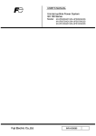
USER’S MANUAL
Uninterruptible Power Supply
GX 200 Series
Model
M-UPS050AD2B
M-UPS075AD2B
M-UPS100AD2B
INR-HG5687
For Safe Use
About handling of this manual
This manual describes important information for using this product safely. Please read
this manual carefully before using this product. Use this product, after reading and
understanding especially "Caution about Safety" and "Caution for Use" in this manual
well. Furthermore, this manual should be retained for future reference.
About “Use which Requires High Safety”
This product is designed and manufactured for the general use, such as general office use
and personal use, and is not designed and manufactured for uses (control of nuclear
reactions at the nuclear facilities, aircraft flight control, air traffic control, mass transport
control, medical life support systems, and missile launch control in weapon systems, etc.)
that require a high degree of safety, and can cause death or serious injury if the required
safety is not maintained. Do not use this product without carrying out measures to ensure
the required safety for such a use. If using this product for such a use, consult with our
sales representatives.
About Prevention of Radio Interference
Important
This product is class A information technology equipment based on the standard of
Voluntary Control Council for Interference by Information Technology Equipment
(VCCI). Using this product in a residential area may cause radio interference. In this
case, the user may be requested to take an appropriate measure.
About Prevention of Harmonic Current Interference
M-UPS050AD2B conforms to the Guideline of harmonic restraint measures for
general-purpose UPS.
M-UPS075AD2B and M-UPS100AD2B conform to IEC61000-3-12.
Do not reproduce or reprint this manual without notice.
c Fuji Electric Co., Ltd. 2011
All Rights Reserved, Copyright ○
Introduction
An uninterruptible power supply is a device for supplying stable electric power to OA
devices, FA devices, and computer devices.
This manual describes installation, running, daily management, troubleshooting, and
maintenance of an uninterruptible power supply. Use an uninterruptible power supply
correctly in accordance with this manual.
In this manual, an uninterruptible power supply (this product) is described as UPS for
short.
Content and organization of this manual
The organization of this manual is as follows:
Caution about Safety and Caution for Use
The cautions about safety are described. If you use the UPS, be sure to read this
section.
1
Unpacking
The cautions about taking out the UPS from a box are described.
2
Outline
The name of each part and the operation mode of the UPS are described.
3
Installation
Installation of the UPS and connection of the cable are described.
4
Running
The methods of run and stop of the UPS are described.
5
Inspection
The cautions about daily inspection and rolling blackouts are described.
6
Troubleshooting
Troubleshooting is described.
7
Maintenance
Replacement of battery and cooling fan and method of storage of the UPS are
described.
8
Appendix
Rated specification and the cautions in UL standard are described.
Due to the purpose to use, the chapters which should be referred to especially are as
follows.
For installation personnel
Caution about Safety, Caution for Use,
Chapters 1, 2, 3, and 4
For users
Caution about Safety, Caution for Use,
Chapters 2, 4, 5, and 6
For maintenance personnel
Caution about Safety, Caution for Use,
Chapters 2, 4, 5, and 7
i
Introduction
About warning display
In this manual, the following warning displays are described so that user or the people
around the UPS do not suffer damage to the body and property.
Warning
Caution
Important
"Warning" indicates that death or serious injury may result, if the
UPS is not used correctly.
"Caution" indicates that slight or moderate injury may result or
the UPS or user’s property may be damaged, if the UPS is not
used correctly.
"Important" indicates caution about the use of the UPS.
About marks in this manual
Marks in this manual have the following meanings:
The state of the UPS is described.
Have a look if necessary. How to deal with, the reference place,
etc. are described.
About symbols of LED
The states of LED are indicated by the following symbols:
: Lighting
: Blinking
: Not lighting
Attention
Information in this manual is subject to change without notice.
ii
Caution about Safety
List of important warnings
The important warnings described in this manual are as follows.
Electric shock
"Warning" indicates that death or serious injury may result, if the
UPS is not used correctly.
Do not remove the cover of the UPS.
Since there are some portions with high voltage in the inside of the
UPS, there is fear of an electric shock.
Caution
"Caution" indicates that slight or moderate injury may result or
the UPS or user’s property may be damaged, if the UPS is not
used correctly.
Warning
Electric shock
Injury
Put neither a stick nor a finger into the cooling fan or the
vent hole.
There is fear of an electric shock or an injury.
Electric shock
Perform the battery and cooling fan replacement by
maintenance personnel.
There is fear of an electric shock.
The UPS should be connected to ground. (more than
class D grounding)
When connecting to an input power supply, connect the
grounding wire to the ground terminal.
There is fear of an electric shock.
Electric shock
Failure
When connecting the UPS to an input power supply,
connect the electric wire of hot-line side to the AC input
terminals L1/R and L2/S, and connect the grounding wire
to the input ground terminal. Likewise, in the connections
between the output of the UPS and the connection device,
connect the electric wire of hot-line side to the AC output
terminals l1/U and l2/V, and connect the grounding wire to
the output ground terminal.
If connected by mistake, there is fear of the malfunction by noise,
the failure, or an electric shock.
When inspecting or maintaining the connection device (a
device getting connected to the UPS) or the UPS, turn off
power of the connection device and stop the operation of
UPS. And turn off the breaker of the distribution board
and cut off connection of AC input terminal.
There is fear of an electric shock.
iii
Caution about Safety
Injury
Do not ride on or put an object on the UPS.
There is fear of an injury or an overturn.
Injury
Damage
The UPS is heavy. Pay enough attention to handling the
UPS.
Take out the UPS in a level and flat place. If you lift the UPS alone
or carry it, there is fear of hurting arms, legs or hip, or dropping the
UPS. Work by a suitable number of persons. And pay enough
attention to prevent an accident such as an overturn or a drop. The
weight of the UPS is as follows:
M-UPS050AD2B : 63kg (without battery : 29kg)
M-UPS075AD2B : 127kg (without battery : 59kg)
M-UPS100AD2B : 127kg (without battery : 59kg)
Fire
Damage
iv
This UPS can be installed laying down. If installing laying
the UPS down, tilt it only to the right side, seeing from the
front. Never tilt the UPS to the left side.
If tilting the UPS to the left side, the liquid leak of a battery may
occur, there is fear of a fire or the UPS failure in the case. If
installing laying the UPS down, be sure to tilt it to the right side.
Caution about Safety
Damage
Do not use the UPS for the uses that may hurt the human
body or exert an important influence on the society and
public.
Medical instrument affecting human life directly
Device that may hurt the human body
Socially and publicly important computer system
Do not put an object (display or floppy disk etc.)
vulnerable to magnetism around the UPS.
There is fear of exerting a bad influence on the object.
Confirm that the voltage set up by the switch of voltage
setting is within the range of input voltage of the
connection device.
There is fear of damaging the connection device.
Do not operate the switch of voltage setting during
operation of the UPS.
There is fear of damaging the connection device, since the changed
voltage is outputted at the restart. And even if operating the switch
during operation of the UPS, the output voltage cannot be changed.
Replace the battery periodically.
If continuing to use the UPS that the battery life ended, there is fear
of a liquid leak of battery, a smoking, and an ignition.
Replace the battery with one specified by our company
and a new one.
If using the un-specified battery or mixing an old battery and a new
battery, it becomes the cause of a liquid leak of battery, a smoking,
an ignition, and the UPS failure and trouble.
When performing the rolling blackouts or when cutting off
an input power supply, perform them after stopping the
operation of the UPS, with reference to Chapter 4.2
"Turning off the UPS" . The stop of operation can be
confirmed by slow blink (in the cycles of approximately
1.6 sec.) of the RUN LED (green).
If cutting off an input power supply when the UPS is operating (the
RUN LED is lighting), the UPS switches to the battery operation
since it will be in the same state as a power failure.
Performing such unnecessary battery operation leads to a shortening
of a cycle of battery replacement.
Warning label
Warning labels are attached to the UPS.
Never remove the labels.
v
Caution for Use
Be careful about the following when using the UPS.
Important
"Important" indicates caution about the use of the UPS.
Do not install and store the UPS in the following places:
In an outdoor location
A place exposed to the elements
An extremely humid place and a dusty place
A place with corrosive gas or salinity
A place subjected to direct sunlight
A place near sparks or heating element
An extremely hot or cold place or place where the temperature fluctuates
greatly
A place where vibration and a shock are added
Do not perform the battery check in succession.
When the battery check is performed, the UPS temporarily switches to the battery
operation.
If the battery check is performed in succession, there is fear of the battery deterioration
or a shortening of a cycle of battery replacement since the battery becomes an
over-discharge state.
If the UPS is not used for a long time, charge the battery every two
months.
The battery is charged by operating the UPS.
For the battery charging time, refer to Chapter 8.1 "Rated Specification".
If the UPS is left without operating for a long time, there is a possibility that the UPS get
unusable since the battery becomes an over-discharge state due to self-discharge.
This UPS is recyclable.
This UPS uses the small sealed lead storage battery. The small sealed lead storage
battery uses expensive and rare resources. However, these precious resources are able to
recycle. Cooperate in recycling without disposing of the used battery.
Do not block the vent hole and cooling fan or use the UPS in a stuffy place.
The vent hole and cooling fan are equipped in order to cool the inside of the UPS.
There is a possibility that the inside and ambient temperature of the UPS may get out of
the rated specification.
Replace the cooling fan periodically.
If continuing to use the UPS that the cooling fan life ended, there is a possibility that the
inside temperature of the UPS may get out of the rated specification.
Do not use 5 to 9 of the switch of voltage setting.
It becomes impossible for the UPS to start up normally.
vi
Caution for Use
The permissible voltage between the input electric cable of the UPS and
the ground is 250V AC.
If the voltage more than 250V AC is applied, the filter circuit of the input part may be
damaged.
The permissible input surge voltage of the UPS is 5kV peak (1.2 50µs).
However, if the model of the UPS is " -UC" and " -C" , it is 2kV peak (1.2
50µs).
If the surge voltage more than 5kV peak ("-UC" and "-C" are 2kV peak) is applied, the
filter circuit of the input part may be damaged.
The input voltage of the UPS is 160 to 288V AC.
When input voltage is different from the rated specification (400V AC etc.), install a
transformer at the outside of the UPS to convert voltage. If the voltage more than the
range of the input voltage is applied, the UPS may be damaged.
Pay attention to an input voltage.
This UPS can operate up to 288V AC. However, an input voltage of the general device is
200V AC ±10%. Therefore, if switching to the bypass operation when applying the
voltage of 220V AC to the UPS, the voltage exceeding specification is applied to the
connection device. Adjust the input voltage to the specification of connection device.
Do not apply single-line grounding on the output side.
Between the input and output of the UPS is not insulated. Therefore, do not apply
single-line grounding on the output side.
There is fear of becoming the cause of the trouble of connection device by noise or the
failure.
When connecting the UPS to the electrical power equipment with the earth
leakage breaker, select the earth leakage breaker not to trip due to current
leakage.
When connecting the UPS to the electrical power equipment with the earth leakage
breaker, select the earth leakage breaker in consideration of total number of current
leakage of the UPS plus current leakage of the connection device.
When connecting the UPS to a three-phase power supply system, be sure
to connect the grounding phase of the three-phase power supply system
to the electrode of a grounding side of the AC input of the UPS.
If connecting to an un-grounding power supply, there is fear of becoming the cause of
the malfunction.
vii
Caution for Use
When using a generator temporarily during the rolling blackouts, use a
generator satisfying the following specification.
If connecting a generator not satisfying the following specification to the input part of
the UPS, there is a possibility of becoming the cause of the malfunction or damage of the
UPS.
Voltage regulation: depend on the input specification of the connection device
Frequency variation: within rated frequency ± 5% (frequency does not change
rapidly)
Voltage waveform distortion: within 5%
Voltage zero-cross condition: Zero-cross must not occur twice or more in 1
cycle.
Illegal zero cross
50Hz or 60Hz
viii
Index
Introduction.......................................................................................................i
Caution about Safety .....................................................................................iii
Caution for Use..............................................................................................vii
1
Unpacking
1.1
2
Outline
2.1
2.2
3
Name and Main Function of Each Part ............................................... 2
Mechanism of the UPS......................................................................... 5
At the normal operation
At the battery operation (In the event of an input power failure)
At the automatic bypass operation
At the manual bypass operation
Installation
3.1
3.2
3.3
3.4
4
Installing the UPS................................................................................. 7
Caution about installation
Determining an installation location
Determining the installation method
Installation method
Connecting the Cable ........................................................................ 12
Caution about connecting the cable
Preparation before connecting the cable
Connecting the output cable
Connecting the input cable
Interface Port ...................................................................................... 16
CN1 (No-voltage contact signal interface)
CN2 (RS-232C interface)
Setting up the Output Voltage ........................................................... 18
The setup procedures of the rated output voltage
Running
4.1
4.2
5
Turning on the UPS............................................................................ 20
Confirming cable connection
Turning on the UPS
Turning on the connection device
Turning off the UPS............................................................................ 23
Turning off the connection device
Turning off the UPS
Inspection
5.1
ix
Opening the Packing ........................................................................... 1
Opening the packing
Confirming the contents of the packing
Care and Daily Inspection ................................................................. 25
How to care for the UPS
Daily inspection
5.2
5.3
6
Caution and Measures for the Rolling Blackouts............................. 27
Operation before the rolling blackouts
Operation after the rolling blackouts
Inspecting the Battery (Battery Check)............................................. 29
Confirming the state of the UPS
Using the manual check function
Charging the battery
Troubleshooting
6.1
6.2
7
If a Warning Beep Sounds ................................................................. 34
Operation Mode List........................................................................... 35
Types of blink of LED
Types of warning beep
Operation mode list
Maintenance
7.2
7.3
8
Replacing the Battery ........................................................................ 40
Timing of the battery replacement
The method of battery replacement
Disposal and storage of battery
Replacing the Cooling Fan ................................................................ 43
Timing of the cooling fan replacement
The method of cooling fan replacement
When Not Using the UPS (Storage)................................................... 45
Work before storage
If a storage period exceeds two months
Appendix
8.1
8.2
Rated Specification ............................................................................ 46
Additional Description for UL Type................................................... 48
x
1
1.1
Unpacking
Opening the Packing
Opening the packing
Caution
Injury
Damage
The UPS is heavy. Pay enough attention to handling the UPS.
Take out the UPS in a level and flat place. If you lift the UPS alone or
carry it, there is fear of hurting arms, legs or hip, or dropping the UPS.
Work by a suitable number of persons. And pay enough attention to
prevent an accident such as an overturn or a drop. The weight of the UPS
is as follows:
M-UPS050AD2B :
63kg (without battery: 29kg)
M-UPS075AD2B : 127kg (without battery: 59kg)
M-UPS100AD2B : 127kg (without battery: 59kg)
1. Open the packing box and take out the UPS.
Confirming the contents of the packing
2. Confirm that there is no damage in the appearance of the UPS.
3. Confirm that all accessories are contained.
UPS model
M-UPS050AD2B
(5kVA)
M-UPS075AD2B
(7.5kVA)
M-UPS100AD2B
(10kVA)
Accessories
User’s manual (this document)
Guarantee (this document)
Stabilizer (with 6 setscrews)
User’s manual (this document)
Guarantee (this document)
Stabilizer (with 6 setscrews)
User’s manual (this document)
Guarantee (this document)
Stabilizer (with 6 setscrews)
If the UPS got damaged, or accessories are missing:
Contact an agent from which you purchased the UPS.
-1-
No. of pcs
1 copy
1set
1 copy
1set
1 copy
1set
2
Outline
2.1
Name and Main Function of Each Part
This chapter describes the name and main function of each part of the UPS.
〈M-UPS050AD2B〉
(6)
(1)
(2)
N
RU
M
AR
AL
AD
LO
ER
OV
SS
PA
BY
(3)
(7)
T
SE
RE
Y
ER N
TT ITIO
BA N D
CO
(4)
(5)
TT
BA ECK
CH
U
P
S
(19)
(8)
(18) (17)
(10)
(15)
(12)
(9)
(16)
(13)
(11)
(14)
-2-
2.1 Name and Main Function of Each Part
〈M-UPS075AD2B, M-UPS100AD2B〉
(1)
(2)
(6)
(7)
(3)
(4)
(5)
(16)
(8)
(19)
(18)
(17)
(10)
(12)
(11)
(14)
(13)
(9)
-3-
(15)
2 Outline
Name
RUN
(2)
ALARM
(3)
OVER LOAD
(4)
LED
(1)
BYPASS
BATTERY
CONDITION
(6)
RUN/STOP
(7)
RESET
(8)
Switch
(5)
BATT CHECK
BYPASS
(9)
Vent hole (cooling fan)
(10)
(11)
(12)
(13)
(14)
(15)
Cooling fan
Input terminal block
Input breaker
Output terminal block
Ground terminal
Switch of voltage setting
Main function
It lights up (green) while the UPS is operating normally.
It lights up (orange) when the abnormalities occurred inside the
UPS.
It lights up (orange) when the load capacity of the connection
device exceeded the rated specification.
It lights up (orange) while the UPS is performing the bypass
operation.
When the battery is normal, it indicates the amount of battery
charge according to the sort of lighting (green).
(Not lighting:0 to 50%, Blinking:50 to 80%, Lighting:80 to 100%)
When the battery is abnormal, it lights up (orange).
It is the switch for performing operation and stop of the UPS.
RUN and STOP are switched every time this switch is pressed for
approximately 1 second.
Press this switch when stopping the warning beep. Also, if this
switch is pressed for approximately 3 seconds after the failure is
restored, the ALARM LED goes out.
It is the switch for performing the battery check manually. By
pressing the switch for approximately 2 seconds, the battery check
is performed.
Press switch (7) and (8) for approximately 3 seconds
simultaneously when switching to the bypass operation forcibly
(manually) while the UPS is operating normally. When the
switches are pressed for approximately 3 seconds simultaneously
again, the UPS returns to the normal operation.
The inside of the UPS is ventilated and cooled. The direction of air
is intake.
The inside of the UPS is cooled. The direction of air is exhaust.
Connect to an input power supply.
It is the breaker for protecting the input circuit.
Connect to an output system.
Connect a grounding wire.
Set up the output voltage.
(16) Dummy board
Mount various option outlets. (-U, -UC type is no option)
(17) Interface slot
Mount various interface cards.
(18) Contact signal (CN1)
Output a no-voltage contact signal.
(19) RS-232C (CN2)
It is RS-232C interface.
-4-
2.2 Mechanism of the UPS
2.2
Mechanism of the UPS
At the normal operation
While the UPS is operating normally, the UPS operates an AC power supply as an
input, and supplies the output of constant voltage to connection device. Simultaneously,
the UPS charges an internal battery and prepares for the battery operation.
Output frequency synchronizes with input frequency.
[ UPS ]
Bypass
+
AC/AC converter
Boost chopper
Charger
:Power is fed
Battery
:Power is not fed
Output
To connection device
Input power supply
Electricity flow during normal operation
At the battery operation (In the event of an input power failure)
When the power failure or the abnormalities of voltage or frequency of an input power
supply occur while the UPS is operating, the UPS starts the electric discharge from the
battery, and continues to supply the stable electric power to the connection device. In
addition, the changeover to the battery operation is performed without instantaneous
power interruption.
If the input power supply returns (the voltage of the input power supply returns within
the rated specification), the UPS will return to the above normal operation automatically.
[ UPS ]
Bypass
+
AC/AC converter
Boost chopper
Charger
:Power is fed
Battery
The abnormalities
occur at an input
power supply.
:Power is not fed
Output
To connection device
While the UPS is operating,
- Power failure
- The abnormalities of voltage or frequency
etc.
Electricity flow during battery operation
-5-
2 Outline
At the automatic bypass operation
When the abnormalities occurred in the UPS during the normal operation, the UPS
switches to the bypass operation automatically. During the bypass operation, the UPS
sends the input voltage to the output directly and supplies the electric power to the
connection device. In this operation state, even if the power failure occurs, the UPS
becomes the power failure state without switching to the battery operation.
[ UPS ]
Bypass
+
AC/AC converter
An error
occurs
inside
Boost
chopper
the UPS
Charger
:Power is fed
Battery
:Power is not fed
Output
To connection device
Input power supply
- The abnormalities inside the UPS
Electricity flow during automatic bypass operation
At the manual bypass operation
It is possible to switch to the bypass operation manually during the normal operation.
Press the RESET switch and the BYPASS switch for approximately 3 seconds
simultaneously to switch to the bypass operation.
When the switches are pressed for approximately 3 seconds simultaneously again, the
UPS returns to the normal operation. In this operation state, even if the power failure
occurs, the UPS becomes the power failure state without switching to the battery
operation.
[ UPS ]
Bypass
+
AC/AC converter
Boost chopper
Charger
Input power supply
:Power is fed
Battery
Switching to the bypass
operation manually
:Power is not fed
Output
To connection device
Electricity flow during manual bypass operation
-6-
3
3.1
Installation
Installing the UPS
Caution about installation
Caution
Injury
Do not ride on or put an object on the UPS.
There is fear of an injury or an overturn.
Damage
Do not put an object (display or floppy disk etc.) vulnerable to
magnetism around the UPS.
There is fear of exerting a bad influence on the object.
Determining an installation location
Important
Do not install the UPS in the following places:
In an outdoor location
A place exposed to the elements
An extremely humid place and a dusty place
A place with corrosive gas or salinity
A place subjected to direct sunlight
A place near sparks or heating element
An extremely hot or cold place or place where the temperature fluctuates
greatly
A place where vibration and a shock are added
Do not use the UPS in a residential area or its adjacent area.
This UPS is class A information technology equipment based on the standard of
Voluntary Control Council for Interference by Information Technology Equipment
(VCCI). Using this UPS in a residential area may cause radio interference. In this case,
the user may be requested to take an appropriate measure.
Do not block the vent hole and cooling fan or use the UPS in a stuffy
place.
The vent hole and cooling fan are equipped in order to cool the inside of the UPS.
There is a possibility that the inside and ambient temperature of the UPS may get out
of the rated specification.
-7-
3 Installation
Front side
Rear side
The following spaces are required for an installation location.
The UPS takes in air through the vent hole on the front of the UPS and
exhausts air through the cooling fan on the back of the UPS. Therefore, the
space of 10cm or more is required in the front and rear of the UPS.
Intake
air
Exhaust
air
UPS
10cm
or more
10cm
or more
Right side
When performing maintenance of the UPS:
The space of approximately 1m is required in the front and rear of the UPS.
Space for
cooling fan
maintenance
Approx. 1m
UPS
Rear side
Front side
Space for cooling
fan and battery
maintenance
Approx. 1m
Right side
Confirm the environment of the installation location. The recommended environment in
consideration of the battery life etc. is as follows.
Item
Temperature
Humidity
Recommended environment
15 to 25 degrees C
30 to 70% (no condensation)
-8-
3.1 Installing the UPS
Determining the installation method
Caution
Fire
Damage
This UPS can be installed laying down. If installing laying the
UPS down, tilt it only to the right side, seeing from the front.
Never tilt the UPS to the left side.
If tilting the UPS to the left side, the liquid leak of a battery may occur,
there is fear of a fire or the UPS failure in the case. If installing laying the
UPS down, be sure to tilt it to the right side.
This UPS can be put in a 19-inch rack using the optional rack mount
attachment kit.
-9-
3 Installation
Installation method
Caution
Injury
Damage
The UPS is heavy. Pay enough attention to handling the UPS.
Take out the UPS in a level and flat place. If you lift the UPS alone or
carry it, there is fear of hurting arms, legs or hip, or dropping the UPS.
Work by a suitable number of persons. And pay enough attention to
prevent an accident such as an overturn or a drop. The weight of the UPS
is as follows:
M-UPS050AD2B :
63kg (without battery: 29kg)
M-UPS075AD2B :
127kg (without battery: 59kg)
M-UPS100AD2B :
127kg (without battery: 59kg)
1. When using the UPS as the self-standing type, tilt the UPS to the right tenderly and
attach the attached stabilizer to the bottom of the UPS with 6 screws. (refer to the
following figure)
〈M-UPS050AD2B〉
〈M-UPS075AD2B, M-UPS100AD2B〉
- 10 -
3.1 Installing the UPS
2. After attaching the stabilizer to the UPS, be sure to fix the stabilizer to the floor.
〈M-UPS050AD2B〉
212
197
330
181
〈M-UPS075AD2B, M-UPS100AD2B〉
338
189.5
- 11 -
330
251.5
3 Installation
3.2
Connecting the Cable
Caution about connecting the cable
Caution
Electric
shock
The UPS should be connected to ground. (more than class D
grounding)
When connecting to an input power supply, connect the
grounding wire to the ground terminal.
There is fear of an electric shock.
Important
The permissible voltage between the input electric cable of the UPS and
the ground is 250V AC.
If the voltage more than 250V AC is applied, the filter circuit of the input part may be
damaged.
The permissible input surge voltage of the UPS is 5kV peak (1.2 50µs).
However, if the model of the UPS is " -UC" and " -C" , it is 2kVpeak (1.2
50µs).
If the surge voltage more than 5kV peak ("-UC" and "-C" are 2kV peak) is applied, the
filter circuit of the input part may be damaged.
The input voltage of the UPS is 160 to 288V AC.
When input voltage is different from the rated specification (400V AC etc.), install a
transformer at the outside of the UPS to convert voltage. If the voltage more than the
range of the input voltage is applied, the UPS may be damaged.
Pay attention to an input voltage.
This UPS can operate up to 288V AC. However, an input voltage of the general device
is 200V AC ±10%. Therefore, if switching to the bypass operation when applying the
voltage of 220V AC to the UPS, the voltage exceeding specification is applied to the
connection device. Adjust the input voltage to the specification of connection device.
Do not apply single-line grounding on the output side.
Between the input and output of the UPS is not insulated. Therefore, do not apply
single-line grounding on the output side.
There is fear of becoming the cause of the trouble of connection device by noise or the
failure.
- 12 -
3.2 Connecting the Cable
Preparation before connecting the cable
Important
When connecting the UPS to the electrical power equipment with the
earth leakage breaker, select the earth leakage breaker not to trip due to
current leakage.
When connecting the UPS to the electrical power equipment with the earth leakage
breaker, select the earth leakage breaker in consideration of total number of current
leakage of the UPS plus current leakage of the connection device.
When connecting the UPS to a three-phase power supply system, be sure
to connect the grounding phase of the three-phase power supply system
to the electrode of a grounding side of the AC input of the UPS.
If connecting to an un-grounding power supply, there is fear of becoming the cause of
the malfunction.
When using a generator temporarily during the rolling blackouts, use a
generator satisfying the following specification.
If connecting a generator not satisfying the following specification to the input part of
the UPS, there is a possibility of becoming the cause of the malfunction or damage of
the UPS.
Voltage regulation: depend on the input specification of the connection
device
Frequency variation: within rated frequency ± 5% (frequency does not
change rapidly)
Voltage waveform distortion: within 5%
Voltage zero-cross condition: Zero-cross must not occur twice or more in 1
cycle.
Illegal zero cross
50Hz or 60Hz
1. Confirm the input power supply. The input power supply which can connect with
this UPS is as follows.
UPS model
M-UPS
050AD2B
(5kVA)
M-UPS
075AD2B
(7.5kVA)
M-UPS
100AD2B
(10kVA)
Breaker
capacity
Input
capacity
40A or
more
5kVA or
more
50A or
more
7.5kVA or
more
75A or
more
10kVA or
more
- 13 -
Input
voltage
Input
frequency
Number of
phase
160 to 288V
AC
50/60Hz
± 5% (Note)
Single-phase
two-wire
3 Installation
Remarks If the input voltage and the frequency are out of this range, the UPS will
become the following state or be damaged.
When the UPS is turned on:
The UPS will become the "input error at startup". In this case, the UPS
cannot be started up.
While the UPS is operating:
"Abnormalities of input voltage" is detected and the battery operation is
performed. If the UPS is connected to an input power supply which gets
out of this range frequently, by repeating the charge and discharge of
the battery, the battery will be in an empty state or will become the
cause of deterioration.
Note) The input frequency of the using area is chosen automatically.
2. The specification of the terminal block is as follows. Select the crimp contact which
is suitable for specification.
〈M-UPS050AD2B〉
UPS side
Specification
Terminal
marking
L1/R
Input and
output
terminal block
L2/S
PE(G)
l1/U
l2/V
Connect with
Connection
Figuration
AC input
(un-grounding side)
AC input
(un-grounding side)
Ground
(protective
grounding)
AC output
(un-grounding side)
AC output
(un-grounding side)
5 pole
screw
terminal
(M5)
Input power supply
and output system
〈M-UPS075AD2B, M-UPS100AD2B〉
UPS side
Specification
Terminal
marking
L1/R
L2/S
Input and
output
terminal block
PE(G)
PE(G)
l1/U
l2/V
Connect with
Connection
Figuration
AC input
(un-grounding side)
AC input
(un-grounding side)
Ground
(protective
grounding)
Ground
(protective
grounding)
AC output
(un-grounding side)
AC output
(un-grounding side)
6 pole
screw
terminal
(M8)
- 14 -
Input power supply
and output system
3.2 Connecting the Cable
Connecting the output cable
Remove the input and output terminal block cover on the back of the UPS, and connect
the AC output cable to the output terminal block.
Confirm that the ground is connected.
Connecting the input cable
Remove the input and output terminal block cover on the back of the UPS, and connect
the AC input cable to the input terminal block.
Confirm that the ground is connected.
- 15 -
3 Installation
Interface Port
The interface port (D-sub 9 pins) is mounted on the back of the UPS and can take out the
following signals. Use as necessary.
CN1 (No-voltage contact signal interface)
1 2 3 4 5
6 7 8 9
D-sub 9 pins, male
(3 mm screw)
Pin
No.
Classification
of signal
1-4
"Open"
at operation
1-6
"Close"
at operation
2-5
"Open"
at operation
2-7
"Close"
at operation
3-9
"Open"
at operation
3-8
"Close"
at operation
Name of
signal
Content
UPS failure
signal
It is the no-voltage contact signal which
operates when the abnormalities occur
inside the UPS, when the abnormalities
occur in the battery, or when the
recommendation
time
of
battery
replacement comes.
Input power
supply
abnormal signal
It is the no-voltage contact signal which is
outputted when the abnormalities, such as
the power failure, occur at an input power
supply. (In the power failure for 1.5
seconds or less, it does not operate.)
Battery voltage
drop signal
It is the no-voltage contact signal which is
outputted approximately 2 minutes before
(at the rated load) the end of battery
discharge during the battery operation.
Use the contact output in the range of the voltage and current in the following graph.
Contact current (A)
3.3
1.0
①
①:AC Contact rating
②:DC Contact rating
②
0.5
0.2
0.1
0.05
10
30
60
120 200
Contact voltage (V)
- 16 -
3.3 Interface Port
CN2 (RS-232C interface)
5 4 3 2 1
9 8 7 6
D-sub 9 pins, female
(#4-40 inch screw)
Pin
No.
Classification
of signal
2-3
"Close"
at operation
1-3
"Close"
at operation
8-7
AC output stop
at ‘H’ signal
reception
6-7
9-7
7
*1
*2
*3
RS-232C serial
signal
(*3)
Name of
signal
Input power
supply
abnormal signal
(*1)
Battery voltage
drop signal
(*1)
Content
It is the no-voltage contact signal which is
outputted when the abnormalities, such as
the power failure, occur at an input power
supply. (In the power failure for 1.5
seconds or less, it does not operate)
It is the no-voltage contact signal which is
outputted approximately 2 minutes before
(at the rated load) the end of battery
discharge during the battery operation.
It is the signal which is inputted into the
UPS when stopping the AC output of the
UPS automatic UPS.
shutdown signal (1) The stop of the AC output is possible
(*2)
only during the battery operation.
(2) Input this signal (5 to 25V DC)
approximately 0.6 seconds or more.
Serial data
input (RX)
Serial data
output (TX)
Signal ground
(SG)
[Communication system]
Baud rate
: 2400 bps
Data length
: 8 bits
Stop bit
: 1 bit
Parity
: non
Character type
: ASCII
Refer to the graph of the previous page for contact capacity.
When using the UPS monitoring function (using the above contact signal)
preinstalled in the following OS, contact your maintenance staff, since the dedicated
cable for contact signal which corresponds to each OS is needed separately. For
more detail on the UPS monitoring function preinstalled in each OS, refer to an
instructions manual, an on-line manual, etc. of each OS.
Windows NT/2000/XP:FiFH/WS9 (the dedicated cable for contact signal)
In the case of Windows 2000 and XP, although the shutdown of OS can be
performed during the power failure, a subsequent UPS automatic shutdown cannot
be performed.
When performing the RS-232C serial communication, contact your maintenance
staff, since the dedicated cable for RS-232C communication is needed separately.
FiFA/WS9 (the dedicated cable for RS-232C communication)
- 17 -
3 Installation
3.4
Setting up the Output Voltage
This UPS can change the rated output voltage by the switch of voltage setting on the back
of the UPS.
Caution
Damage
Confirm that the voltage set up by the switch of voltage
setting is within the range of input voltage of the connection
device.
There is fear of damaging the connection device.
Do not operate the switch of voltage setting during operation
of the UPS.
There is fear of damaging the connection device, since the changed
voltage is outputted at the restart. And even if operating the switch
during operation of the UPS, the output voltage cannot be changed.
Important
Do not use 5 to 9 of the switch of voltage setting.
It becomes impossible for the UPS to start up normally.
The setup procedures of the rated output voltage
1. Turn off the connection device.
2. Press the RUN/STOP switch on the front of the UPS for approximately 1 second.
The buzzer will sound if the switch is received.
3. An output stops.
The RUN LED (green) on the front of the UPS blinks slowly (in the cycles of
approximately 1.6 sec.).
4. Turn off the input breaker on the back of the UPS.
5. After confirming that all LEDs on the front of the UPS have gone out, operate the
switch of voltage setting on the back of the UPS. The rated output voltage
corresponding to a setup of the switch of voltage setting is shown below.
Setup of the switch of voltage setting
Rated output voltage
0
1
2
3
4
5-9
200V AC
208V AC
220V AC
230V AC
240V AC
They are not used.
6. Turn on the input breaker on the back of the UPS.
The RUN LED (green) on the front of the UPS blinks slowly (in the cycles of
approximately 1.6 sec.).
- 18 -
3.4 Setting up the Output Voltage
7. Press the RUN/STOP switch on the front of the UPS for approximately 1 second.
The buzzer will sound if the switch is received.
8. AC voltage set up is outputted from the output terminal block. The RUN LED
(green) on the front of the UPS lights up.
9. Turn on the connection device, if the normal operation is started with the rated
voltage set up.
- 19 -
4
4.1
Running
Turning on the UPS
Caution
Damage
Confirm that the voltage set up by the switch of voltage setting
is within the range of input voltage of the connection device.
There is fear of damaging the connection device.
Confirming cable connection
1. Confirm that the UPS is connected to an input power supply and the connection
device.
When turning on the input breaker on the back of the UPS, the RUN LED (green) on
the front of the UPS blinks slowly (in the cycles of approximately 1.6 sec.).
〈M-UPS050AD2B〉
〈M-UPS075AD2B, M-UPS100AD2B〉
N
RU
M
AR
AL
AD
LO
R
E
OV
SS
PA
BY
T
SE
RE
Y
ER N
TT ITIO
BA ND
CO
TT K
BA EC
CH
U
P
S
If the UPS is not connected:
Refer to Chapter 3.2 "Connecting the Cable".
- 20 -
4.1 Turning on the UPS
Turning on the UPS
2. Press the RUN/STOP switch on the front of the UPS for approximately 1 second.
The buzzer will sound if the switch is received.
〈M-UPS050AD2B〉
〈M-UPS075AD2B, M-UPS100AD2B〉
Press the RUN/STOP switch
for approximately 1 second.
N
RU
M
AR
AL
AD
LO
ER
V
O
SS
PA
BY
T
SE
RE
Y
ER N
TT ITIO
BA ND
CO
TT K
BA EC
CH
U
P
S
3. AC voltage is outputted from the output terminal block.
The RUN LED (green) on the front of the UPS lights up.
The BATTERY CONDITION LED (green) on the front of the UPS indicates the
amount of battery charge according to the sort of lighting.
〈M-UPS050AD2B〉
〈M-UPS075AD2B, M-UPS100AD2B〉
The RUN LED(green)lights
up.
N
RU
M
AR
AL
AD
LO
R
E
OV
SS
PA
BY
T
SE
RE
Y
ER N
TT ITIO
BA ND
CO
TT K
BA EC
CH
U
P
S
The indication (green) of the
amount of battery charge
Lighting:80 to 100%
Blinking:50 to 80%
Not lighting:0 to 50%
- 21 -
4 Running
4. The battery check is performed automatically.
The BATTERY CONDITION LED (orange) on the front of the UPS blinks (in the
cycles of approximately 1.6 sec.).
〈M-UPS050AD2B〉
〈M-UPS075AD2B, M-UPS100AD2B〉
N
RU
M
AR
AL
AD
LO
ER
V
O
SS
PA
BY
T
SE
RE
Y
ER N
TT ITIO
A
D
B N
CO
TT K
BA EC
CH
U
P
S
5. The battery check is performed for approximately 5 seconds. Then, if the battery is
normal, the BATTERY CONDITION LED (green) on the front of the UPS indicates
the amount of battery charge again, and the UPS returns to the normal operation.
If the normal operation is not started:
Refer to Chapter 6 "Troubleshooting".
Turning on the connection device
6. Turn on the connection device if the normal operation is started.
- 22 -
4.2 Turning off the UPS
4.2
Turning off the UPS
Also when the rolling blackouts are performed, be sure to perform the following
operation. (For details, refer to Chapter 5.2 "Caution and Measures for the Rolling
Blackouts")
Caution
Damage
When performing the rolling blackouts or when cutting off an
input power supply, perform them after stopping the operation
of the UPS, with reference to Chapter 4.2 "Turning off the UPS".
The stop of operation can be confirmed by slow blink (in the
cycles of approximately 1.6 sec.) of the RUN LED (green).
If cutting off an input power supply when the UPS is operating (the RUN
LED is lighting), the UPS switches to the battery operation since it will be
in the same state as a power failure.
Performing such unnecessary battery operation leads to a shortening of a
cycle of battery replacement.
Turning off the connection device
1. Turn off the connection device.
Turning off the UPS
2. Press the RUN/STOP switch on the front of the UPS for approximately 1 second.
The buzzer will sound if the switch is received.
〈M-UPS050AD2B〉
〈M-UPS075AD2B, M-UPS100AD2B〉
Press the RUN/STOP switch
for approximately 1 second.
N
RU
M
AR
AL
AD
LO
ER
V
O
SS
PA
BY
T
SE
RE
Y
ER N
TT ITIO
BA ND
CO
TT K
BA EC
CH
U
P
S
- 23 -
4 Running
3. An output stops.
The RUN LED (green) on the front of the UPS blinks slowly (in the cycles of
approximately 1.6 sec.).
〈M-UPS050AD2B〉
〈M-UPS075AD2B, M-UPS100AD2B〉
N
RU
M
AR
AL
AD
LO
R
E
OV
SS
PA
BY
T
SE
RE
Y
ER N
TT ITIO
A
B ND
CO
TT K
BA EC
CH
U
P
S
If an output does not stop normally:
Refer to Chapter 6 "Troubleshooting".
4. Turn off the input breaker on the back of the UPS.
- 24 -
5
5.1
Inspection
Care and Daily Inspection
In order to use the UPS safely over the long term, perform the following care and daily
inspection regularly.
Warning
Electric
shock
Do not remove the cover of the UPS.
Since there are some portions with high voltage in the inside of the UPS,
there is fear of an electric shock.
Caution
Electric
shock
Failure
When inspecting or maintaining the connection device (a
device getting connected to the UPS) or the UPS, turn off power
of the connection device and stop the operation of UPS. And
turn off the breaker of the distribution board and cut off
connection of AC input terminal.
There is fear of an electric shock.
Electric
shock
Perform the battery and
maintenance personnel.
There is fear of an electric shock.
Damage
When performing the rolling blackouts or when cutting off an
input power supply, perform them after stopping the operation
of the UPS, with reference to Chapter 4.2 "Turning off the UPS".
The stop of operation can be confirmed by slow blink (in the
cycles of approximately 1.6 sec.) of the RUN LED (green).
If cutting off an input power supply when the UPS is operating (the RUN
LED is lighting), the UPS switches to the battery operation since it will be
in the same state as a power failure.
Performing such unnecessary battery operation leads to a shortening of a
cycle of battery replacement.
- 25 -
cooling
fan
replacement
by
5 Inspection
How to care for the UPS
1. Turn off the UPS after turning off the connection device, and remove the dust
adhering to the vent hole and cooling fan of the UPS with a cleaner, etc.
2. Wipe the surface of the UPS with a dry and soft cloth.
Daily inspection
Confirm that the dust is not adhering to the vent hole and the cooling fan.
When the dust is adhering:
Refer to "How to care for the UPS".
Confirm that the surface of UPS, the electric cables, and the outlets are not heating
unusually.
When they are heating:
Confirm the state, and contact an agent from which you purchased the UPS or
a maintenance company.
Confirm that a loud abnormal sound or a nasty smell is not occurring during the
operation of the UPS.
When abnormalities have occurred:
Confirm the state, and contact an agent from which you purchased the UPS or
a maintenance company.
- 26 -
5.2 Caution and Measures for the Rolling Blackouts
5.2
Caution and Measures for the Rolling Blackouts
Important
When using a generator temporarily during the rolling blackouts, use a
generator satisfying the following specification.
If connecting a generator not satisfying the following specification to the input part of
the UPS, there is a possibility of becoming the cause of the malfunction or damage of
the UPS.
Voltage regulation: depend on the input specification of the connection
device
Frequency variation: within rated frequency ± 5% (frequency does not
change rapidly)
Voltage waveform distortion: within 5%
Voltage zero-cross condition: Zero-cross must not occur twice or more in 1
cycle.
Illegal zero cross
50Hz or 60Hz
Operation before the rolling blackouts
Turn off the connection device and the UPS before performing the rolling blackouts
(Note).
1. Turn off the connection device.
2. Press the RUN/STOP switch on the front of the UPS for approximately 1 second.
The buzzer will sound if the switch is received.
3. An output stops.
The RUN LED (green) on the front of the UPS blinks slowly (in the cycles of
approximately 1.6 sec.).
If the rolling blackouts are performed without turning off the UPS, the UPS will be in the
same state as an ordinary power failure. Electric power is supplied to the connection
device from the internal battery of the UPS until the rolling blackouts are completed.
Electric power is not supplied to the connection device until an input power supply
returns after the electric discharge is completed.
Note) The rolling blackouts mean the blackouts to which the date and hour, such as
the safety inspection of electricity, is informed beforehand.
- 27 -
5 Inspection
Operation after the rolling blackouts
1. Confirm that the UPS is connected to an input power supply and the connection
device.
The RUN LED (green) on the front of the UPS blinks slowly (in the cycles of
approximately 1.6 sec.).
2. Press the RUN/STOP switch on the front of the UPS for approximately 1 second.
The buzzer will sound if the switch is received.
3. AC voltage is outputted from the output terminal block, and the RUN LED (green) on
the front of the UPS lights up.
4. Turn on the connection device if the normal operation is started.
For details, refer to Chapter 4.1 "Turning on the UPS".
When a warning beep sounds:
Refer to Chapter 6.1 "If a Warning Beep Sounds".
- 28 -
5.3 Inspecting the Battery (Battery Check)
5.3
Inspecting the Battery (Battery Check)
Inspection of the battery is performed using a battery check function. There are two kinds
of battery check functions, an automatic check and a manual check.
The manual check is not necessary ordinarily since automatic check is performed while
the UPS is operating.
Automatic check is performed in the following cases:
When the operation of UPS is started up
Every two weeks in an operation continuation state
When the UPS has switched to the normal operation from the bypass operation
Perform manual check in the following cases:
When a warning beep sounds due to the abnormalities in a battery
When performing the battery check other than the automatic check
Important
Do not perform the battery check in succession.
When the battery check is performed, the UPS temporarily switches to the battery
operation.
If the battery check is performed in succession, there is fear of the battery deterioration
or a shortening of a cycle of battery replacement since the battery becomes an
over-discharge state.
Confirming the state of the UPS
1. Confirm that the UPS is operating normally.
〈M-UPS050AD2B〉
〈M-UPS075AD2B, M-UPS100AD2B〉
Confirm that the RUN LED
(green) is lighting.
N
RU
M
AR
AL
AD
LO
R
E
OV
SS
PA
BY
T
SE
RE
Y
ER N
TT ITIO
BA ND
CO
TT
BA ECK
CH
U
P
S
When the UPS is in a stop state (all LED on the front of the UPS goes
out):
Turn on the UPS, and proceed to Procedure 2.
For details, refer to Chapter 4.1 "Turning on the UPS".
When the normal operation cannot be confirmed in states other than a
stop:
Proceed to Procedure 2 after reading Chapter 6 "Troubleshooting" and dealing
with the trouble.
- 29 -
5 Inspection
Using the manual check function
2. Press the BATT CHECK switch on the front of the UPS for approximately 2 seconds.
〈M-UPS050AD2B〉
〈M-UPS075AD2B, M-UPS100AD2B〉
N
RU
M
AR
AL
AD
LO
ER
V
O
SS
PA
BY
T
SE
RE
Y
ER N
TT ITIO
BA ND
CO
TT
BA ECK
CH
U
P
S
Press the BATT CHECK switch
for approximately 2 seconds.
The buzzer sounds, and the BATTERY CONDITION LED (orange)
blinks (in the cycles of approximately 1.6 sec.).
The buzzer sounds again approximately 5 seconds later and the battery
check is completed.
〈M-UPS050AD2B〉
N
RU
N
RU
M
AR
AL
M
AR
AL
ER
OV
AD
LO
SS
PA
BY
Pi ―
―
ER
OV
T
SE
RE
Y
ER N
TT ITIO
BA ND
CO
SS
PA
BY
TT K
BA EC
CH
U
AD
LO
P
A buzzer sounds.
(Not sound)
S
N
RU
M
AR
AL
AD
LO
R
E
OV
SS
PA
BY
T
SE
RE
Y
ER N
TT ITIO
BA ND
CO
TT K
BA EC
CH
U
P
S
The BATTERY CONDITION LED
(orange) blinks.
- 30 -
Pi ―
―
T
SE
RE
Y
ER N
TT ITIO
BA ND
CO
TT K
BA EC
CH
U
P
S
A buzzer sounds.
5.3 Inspecting the Battery (Battery Check)
〈M-UPS075AD2B, M-UPS100AD2B〉
A buzzer sounds.
Pi―
The BATTERY CONDITION LED
(orange) blinks.
(Not
sound)
A buzzer sounds.
Pi―
- 31 -
5 Inspection
3. As a result of the battery check, the UPS will be in the following state.
If the battery is fully charged:
The RUN LED (green) on the front of the UPS lights up, and the UPS
returns to the normal operation.
〈M-UPS050AD2B〉
〈M-UPS075AD2B, M-UPS100AD2B〉
The RUN LED(green)lights up.
N
RU
M
AR
AL
AD
LO
ER
V
O
SS
PA
BY
T
SE
RE
Y
ER N
TT ITIO
BA ND
CO
TT
BA ECK
CH
U
P
S
If the battery is not fully charged:
A warning beep sounds and the BATTERY CONDITION LED (orange)
on the front of the UPS blinks.
Proceed to Procedure 4.
〈M-UPS050AD2B〉
〈M-UPS075AD2B, M-UPS100AD2B〉
Pip-pippip-pip・・・
(continuous
sound)
N
RU
M
AR
AL
AD
LO
ER
V
O
SS
PA
BY
T
SE
RE
Y
ER N
TT ITIO
BA ND
CO
TT K
BA EC
CH
U
P
The BATTERY
CONDITION LED (orange)
blinks.
S
- 32 -
5.3 Inspecting the Battery (Battery Check)
Charging the battery
4. Put out the BATTERY CONDITION LED (orange) by pressing the RESET switch on
the front of the UPS for approximately 3 seconds, and operate the UPS 12 hours or
more to charge the battery.
When pressing the RESET switch, once the BATTERY CONDITION
LED (orange) on the front of the UPS goes out, and is switched to the
indication (green) of the amount of battery charge.
〈M-UPS050AD2B〉
〈M-UPS075AD2B, M-UPS100AD2B〉
Press the RESET switch.
N
RU
M
AR
AL
AD
LO
ER
V
O
SS
PA
BY
T
SE
RE
Y
ER N
TT ITIO
BA ND
CO
TT
BA ECK
CH
U
P
S
Remarks. In this state, even if a power failure occurs, the battery operation may not
be performed.
5. Return to Procedure 2, and perform the battery check again manually.
When the UPS will be in the state of Procedure 3 “If the battery is not
fully charged” again:
The battery is out of order (end of battery life). Replace the battery.
For details, refer to Chapter 7.1 "Replacing the Battery".
- 33 -
6
6.1
Troubleshooting
If a Warning Beep Sounds
1. Confirm the state of LED on the front of the UPS, and the type of a warning beep.
2. Refer to the "Operation mode list", and deal with it according to directions.
If the UPS is not connected to an input power supply, connect. For details, refer to
Chapter 3.2 "Connecting the Cable".
How to stop a warning beep:
A warning beep can be stopped by pressing the RESET switch on the front of the
UPS for approximately 1 second. (Note)
However, if a warning beep does not stop even if pressing the RESET switch,
stop a warning beep by the following procedures. For details, refer to Chapter 4.2
"Turning off the UPS".
(1) Turn off the connection device.
(2) Press the RUN/STOP switch on the front of the UPS for approximately 1
second.
(3) An output stops.
The RUN LED (green) on the front of the UPS blinks slowly (in the cycles
of approximately 1.6 sec.).
(4) Turn off the input breaker on the back of the UPS.
Note) In the output overload state, even if pressing the RESET switch, a warning
beep does not stop. Reduce the capacity of the connection device to less than
the rated value of the UPS.
- 34 -
6.2 Operation Mode List
6.2
Operation Mode List
When it seems that the abnormalities occur inside the UPS or the connection device stops,
confirm the LED and a warning beep by the following lists, and deal with the trouble in
accordance with the remarks in the "Operation mode list".
Types of blink of LED (The symbols correspond to the symbols
in the " Operation mode list" .)
Symbol
(a)
(b)
Blink pattern
Fast blink
(in the cycles of
approximately 0.4 sec.)
ON OFF
Slow blink
(in the cycles of
approximately 1.6 sec.)
ON
Approximately 0.4 sec.
OFF
Approximately 1.6 sec.
Types of warning beep (The symbols correspond to the
symbols in the " Operation mode list" .)
Symbol
(1)
Warning beep
Pip-pip-pip-pip・・・
(continuous sound)
(2)
Pip-pip-pip-pip (a stop
for approximately 2
sec.)
Pip-pip-pip-pip
(four times every
approximately 3 sec.)
(3)
Pi—
(continuance)
(4)
Pi— (a stop for
approximately 4 sec.)
Pi—
ON OFF
Approximately 0.2 sec.
ON OFF
Approximately 0.2 sec.
Approximately
3 sec.
ON continuously
- 35 -
ON
OFF
Approximately 1 sec.
ON
Approximately 5 sec.
6 Troubleshooting
Operation mode list
Symbols of LED:
···· Lighting
········· Not lighting
········ Blinking
The BATTERY CONDITION LED (green) indicates the amount of battery charge
according to the sort of lighting as follows:
(Not lighting)········· 0 to 50% : The battery is not fully charged. Even if a
power failure occurs, the UPS may not be
able to back up.
(Blinking)·············· 50 to 80% : The battery is charged to some extent,
however, an adequate backup time cannot be
assured.
(Lighting) ·············· 80 to 100% : The battery is fully charged. There is backup
time at full.
LED
No.
1
RUN
(green)
Lighting
ALARM
(orange)
OVER
LOAD
(orange)
BATTERY Warning
BYPASS CONDITION
beep
(orange)
(green/
orange)
Operational
status
Indication
of the
amount of
battery
charge
(green)
-
Normal
operation
-
Stopping
(without an
input power
supply)
2
3
(b)
Slow
blink
-
- 36 -
Remarks
The UPS is operating normally.
The output of the UPS is stopping.
If an input power supply returns,
the UPS will become the stopping
(No.3). If the UPS does not become
the stopping (No.3) even if an input
power supply returns, check
whether or not the input breaker
has tripped. If the breaker has
tripped, reset it. If the UPS still
does not become the stopping
(No.3), contact an agent from
which you purchased the UPS or a
maintenance company.
When the UPS stopped since the
input power failure continued and
electric discharge of a battery was
completed, the UPS will return to
the normal operation (No.1)
automatically if an input power
supply returns.
Stopping
The output of the UPS is stopping.
(with an input The UPS will return to the normal
power supply) operation (No.1) by pressing the
RUN/STOP switch for
approximately 1 second.
6.2 Operation Mode List
LED
No.
RUN
(green)
4
5
ALARM
(orange)
Lighting
OVER
LOAD
(orange)
BATTERY Warning
BYPASS CONDITION
beep
(orange)
(green/
orange)
Operational
status
Lighting
Bypass
The UPS became the failure state
operation due and switched to the bypass
to UPS failure operation. Evacuate important
connection device from the UPS.
In this state, even if an input power
failure occurs, the battery operation
cannot be performed.
Confirm ambient temperature and
ventilation, and press the RESET
switch on the front of the UPS for
approximately 3 seconds after
approximately 10 minutes have
passed. If there is no problem, the
UPS will return to the normal
operation (No.1). If the ALARM
LED does not go out or lights up
again, even after the above
operation is performed, contact an
agent from which you purchased
the UPS or a maintenance
company.
Abnormality Abnormalities have occurred in the
in cooling fan cooling fan.
If this state continues for
approximately 2 minutes or the
inside temperature of the UPS
rises, the UPS will become the
failure state of No.4.
Manual
The UPS has been switched to the
bypass
bypass operation manually. In this
operation
state, even if an input power failure
occurs, the battery operation cannot
be performed.
Input error at Since the abnormalities occur at an
startup
input power supply, the UPS
cannot be started up.
Stop the UPS once, and restart after
confirming that an input power
supply is within the range of the
following conditions.
Input voltage: 160 to 288V AC
Input frequency: 47.5 to 52.5 Hz
or 57 to 63 Hz
Bypass
Since the capacity of the
operation due connection device exceeded the
to an output rated value and the UPS became
overload
the overload state, the UPS has
during the
switched to the bypass operation
normal
automatically. Reduce the capacity
operation
of the connection device to less
than the rated value of the UPS. If
the capacity of the connection
device become below the rated
value, the UPS will return to the
normal operation (No.1). In the
state of the continuation of
overload, even if pressing the
RESET switch, the warning beep
does not stop. Although it may
become the overload temporarily
by inrush current at the time of a
load injection, it is no matter since
it is canceled automatically.
Lighting
(1)
Indication
of the
amount of
battery
charge
(green)
6
(b)
Slow
blink
7
(b)
Slow
blink
8
Lighting
(3)
-
(a)
Fast
blink
(1)
Lighting Lighting
Indication
of the
amount of
battery
charge
(green)
- 37 -
(1)
Remarks
6 Troubleshooting
LED
No.
RUN
(green)
ALARM
(orange)
9
10
OVER
LOAD
(orange)
Lighting
Lighting
11
Lighting
Lighting
BATTERY Warning
BYPASS CONDITION
beep
(orange)
(green/
orange)
(b)
Slow
blink
(1)
Indication
of the
amount of
battery
charge
(green)
Lighting
(1)
(1)
12
Lighting
Indication
of the
amount of
battery
charge
(green)
(2)
13
Lighting
Indication
of the
amount of
battery
charge
(green)
(1)
14
Lighting
(b)
Slow blink
(orange)
(4)
(at the
manual
check)
- 38 -
Operational
status
Output
overload
during the
bypass
operation
Remarks
During the bypass operation, the
capacity of the connection device
exceeds the rated value. Reduce the
capacity of the connection device
to less than the rated value of the
UPS. In this state, even if pressing
the bypass switch (pressing the
RESET switch and the BATT
CHECK switch for approximately
3 seconds simultaneously), the
UPS will not return to the normal
operation (No.1).
Output
During the battery operation, the
overload
capacity of the connection device
during the
exceeds the rated value. Reduce the
battery
capacity of the connection device
operation
to less than the rated value of the
UPS.
If this state continues for 100
seconds, the UPS will stop.
Evacuate important connection
device from the UPS.
A Stop due to Since the UPS continued to be used
an output
even after the capacity of the
overload
connection device had exceeded
the rated value of the UPS, the UPS
stopped. Reduce the capacity of the
connection device to less than the
rated value of the UPS, and restart
the UPS.
Battery
Since the abnormalities occurred at
operation
an input power supply, the UPS
started to supply the electric power
to the connection device from the
battery. It is not necessary to deal
with it especially.
If an input power supply returns,
the UPS will return to the normal
operation (No.1) automatically.
Battery
The battery voltage has dropped
voltage drop since the battery operation
due to
continued. In the rated load, the
continuing the battery operation will be completed
battery
approximately 2 minutes later.
operation
Evacuate important connection
device from the UPS.
If an input power supply returns,
the UPS will return to the normal
operation (No.1) automatically.
Battery
The battery check is performed. At
checking
the manual battery check, a buzzer
sounds at the start and end of the
battery check.
After the battery check is
performed for approximately 5
seconds, the UPS will return to the
normal operation (No.1) if there is
no problem.
6.2 Operation Mode List
LED
No.
RUN
(green)
ALARM
(orange)
OVER
LOAD
(orange)
BATTERY Warning
BYPASS CONDITION
beep
(orange)
(green/
orange)
15
Lighting
(a)
Fast blink
(orange)
(1)
16
Lighting
Lighting
(orange)
(1)
17
(b)
Slow
blink
18
(b)
Slow
blink
(a)
Fast
blink
(1)
(b)
Slow blink
(green)
- 39 -
-
Operational
status
Remarks
Battery check There is possibility that the battery
error
is not fully charged. Perform the
battery check manually after
operating the UPS 12 hours or
more to charge the battery. Since an
adequate backup time cannot be
assured, evacuate important
connection device from the UPS.
If the UPS becomes this state
again, the battery is out of order.
Since it is necessary to replace the
battery, contact an agent from
which you purchased the UPS or a
maintenance company.
End of battery The recommendation time of
life
battery replacement has come.
Since it is necessary to replace the
battery, contact an agent from
which you purchased the UPS or a
maintenance company. Although
the alarm (indication and warning
beep) can be stopped by pressing
the RESET switch for 3 seconds,
the alarm (warning beep) is issued
again 24 hours later or at the
restart. When only the warning
beep is stopped by pressing the
RESET switch 1 second or more,
the alarm (warning beep) of the end
of battery life will be issued again
at the automatic battery check
which is performed every two
weeks.
Setting error A setup of the switch of voltage
of rated output setting on the back of the UPS is
voltage
wrong. Use 0 to 4 of the switch of
voltage setting. For details on a
setup, refer to Chapter 3.4 "Setting
up the Output Voltage".
Waiting for The output of the UPS has stopped
restart
by setup of the RS-232C
communication. After a time
specified at the setup passes, the
UPS will start automatically, and
return to the normal operation
(No.1). Also, the UPS can be
started up with the RUN/STOP
switch.
7.1
Maintenance
Replacing the Battery
Timing of the battery replacement
Caution
Damage
Replace the battery periodically.
If continuing to use the UPS that the battery life ended, there is fear of a
liquid leak of battery, a smoking, and an ignition.
In the following cases, it is the end of battery life. Replace the battery.
When the BATTERY CONDITION LED (orange) on the front of the UPS lights
up and a warning beep sounds
〈M-UPS050AD2B〉
RU
〈M-UPS075AD2B, M-UPS100AD2B〉
Pip-pippip-pip・・・
(continuous
sound)
N
M
AR
AL
ER
OV
AD
LO
S
PA
BY
S
RE
T
SE
Y
ER N
TT I TI O
BA ND
CO
TT K
BA EC
CH
U
P
S
The BATTERY
CONDITION LED (orange)
lights up.
When the backup time of the battery has been lowered to 3 minutes or less (at the
rated load)
Battery life is influenced greatly by ambient temperature and the conditions of
connection device. If using the UPS in the standard environment and
conditions (an ambient temperature of 25 degrees C, and the rated load),
replace the battery in approximately 3 years.
Battery replacement (year)
7
8
5
4
3
2
1
0
25
30
35
40
Ambient temperature of the UPS (℃)
Relation between the ambient temperature
and the timing of the battery replacement
- 40 -
7.1 Replacing the Battery
The method of battery replacement
Caution
Electric
shock
Perform the battery replacement by maintenance personnel.
There is fear of an electric shock.
Damage
Replace the battery with one specified by our company and a
new one.
If using the un-specified battery or mixing an old battery and a new
battery, it becomes the cause of a liquid leak of battery, a smoking, an
ignition, and the UPS failure and trouble.
Important
This UPS is recyclable.
This UPS uses the small sealed lead storage battery. The small sealed lead storage
battery uses expensive and rare resources. However, these precious resources are able
to recycle. Cooperate in recycling without disposing of the used battery.
The battery of this UPS can be replaced (hot-swap) without turning off the UPS and
connection device (Note). For details, consult with an agent from which you purchased
the UPS or a maintenance company.
Note) The UPS performs the bypass operation during hot swapping. In the state of
the bypass operation, even if the abnormalities, such as a power failure, occur
at an input power supply, the battery operation cannot be performed.
Use the battery shown in the following list. For the method of purchasing the battery
unit, consult with an agent from which you purchased the UPS or a maintenance
company.
UPS
model
UPS
model
M-UPS
050AD2B
(5kVA)
Battery for
M-UPS
050AD2B
M-UPS
075AD2B
(7.5kVA)
Battery for
M-UPS
075AD2B
M-UPS
100AD2B
(10kVA)
Battery for
M-UPS
100AD2B
Number of
units (Note)
(per UPS)
Type of
battery unit
Battery unit
Mass
Battery
(a unit)
capacity
2 units
Approximately
17kg
RRABU-GX31
4 units
Note) It is necessary to replace the battery by the unit.
- 41 -
12V, 5Ah
8
7 Maintenance
Disposal and storage of battery
Pay enough attention to disposal and storage of the battery. Prevent mixing with a
dry cell, etc. after taking a measure (for example, stick the insulating tape on the
terminal) to prevent a short circuit, when taking out the battery in order to discard.
This UPS uses the small sealed lead storage battery as battery. The small sealed lead
storage battery uses expensive and rare resources. However, these precious
resources are able to recycle. Cooperate in recycling without disposing of the used
battery. If you have any questions, consult with an agent from which you purchased
the UPS or a maintenance company.
This mark is the recycle mark of small sealed lead storage battery.
Pb
- 42 -
7.2 Replacing the Cooling Fan
7.2
Replacing the Cooling Fan
Timing of the cooling fan replacement
Important
Replace the cooling fan periodically.
If continuing to use the UPS that the cooling fan life ended, there is a possibility that
the inside temperature of the UPS may get out of the rated specification.
In the following cases, it is the end of cooling fan life. Replace the cooling fan.
When the ALARM LED (orange) and the BYPASS LED (orange) light up, after a
warning beep sounded for 120 seconds
〈M-UPS050AD2B〉
The ALARM LED
(orange) lights up.
Pi――
(continuance)
N
RU
N
RU
M
AR
AL
AD
LO
ER
V
O
SS
PA
BY
T
SE
RE
Y
ER N
TT ITIO
BA ND
CO
M
AR
AL
AD
LO
R
E
OV
SS
PA
BY
Pip-pippip-pip・・・
(continuous sound)
Y
ER N
TT ITIO
BA ND
CO
TT K
BA EC
CH
U
P
S
T
SE
RE
The BYPASS LED
(orange) lights up.
TT K
BA EC
CH
U
P
〈M-UPS075AD2B, M-UPS100AD2B〉
The ALARM LED
(orange) lights up.
Pi――
(continuance)
The BYPASS LED
(orange) lights up.
Pip-pippip-pip・・・
(continuous sound)
At the second battery replacement
It is necessary to replace the cooling fan with new one periodically, since the cooling fan
has a life by wear of the bearing. However, since the life of cooling fan may become short
according to the use environment, replace the cooling fan early.
- 43 -
S
7 Maintenance
The method of cooling fan replacement
Caution
Electric shock
Injury
Put neither a stick nor a finger into the cooling fan or
the vent hole.
There is fear of an electric shock or an injury.
Electric shock
Perform the cooling fan replacement by maintenance
personnel.
There is fear of an electric shock.
The cooling fan of this UPS can be replaced (hot-swap) without turning off the UPS and
connection device (Note). For details, consult with an agent from which you purchased
the UPS or a maintenance company.
Note) Replacement by hot swapping should be performed in a short time. The UPS
starts the bypass operation, if the internal temperature of the UPS rises (out of
the rated specification). In the state of the bypass operation, even if an input
power failure occurs, the battery operation cannot be performed.
Use the following cooling fan. For the method of purchasing the cooling fan, consult with
an agent from which you purchased the UPS or a maintenance company.
Type of cooling fan :
Fan for M-UPS050AD2B (RRAF-GX11×1 / RRAF-GX12×1)
Fan for M-UPS075AD2B (RRAF-R1×2 / RRAF-GX12×2)
Fan for M-UPS100AD2B (RRAF-R1×2 / RRAF-GX12×2)
- 44 -
7.3 When Not Using the UPS (Storage)
7.3
When Not Using the UPS (Storage)
Work before storage
Important
Do not store the UPS in the following places:
In an outdoor location
A place exposed to the elements
An extremely humid place and a dusty place
A place with corrosive gas or salinity
A place subjected to direct sunlight
A place near sparks or heating element
An extremely hot or cold place or place where the temperature fluctuates
greatly
A place where vibration and a shock are added
1. Charge the battery by operating the UPS 12 hours or more. After charging the
battery, perform the battery check using a battery check function (manual check).
For details, refer to Chapter 5.3 "Inspecting the Battery (Battery Check)".
The period that can store the battery used for this UPS is approximately 2 months
from the state charged fully.
2. Turn off the UPS after turning off the connection device, and turn off the input
breaker on the back of the UPS.
For details, refer to Chapter 4.2 "Turning off the UPS".
3. Put the UPS in a box (the box, etc. which was packing the UPS) and store it.
If a storage period exceeds two months
Important
If the UPS is not used for a long time, charge the battery every two
months.
The battery is charged by operating the UPS.
For the battery charging time, refer to Chapter 8.1 "Rated Specification".
If the UPS is left without operating for a long time, there is a possibility that the UPS
get unusable since the battery becomes an over-discharge state due to self-discharge.
Charge the battery by operating the UPS 12 hours or more every two months. After
charging the battery, perform the battery check using a battery check function (manual
check).
For details, refer to Chapter 5.3 "Inspecting the Battery (Battery Check)".
Even if the UPS is not used, the battery is discharged by itself inside the UPS. If leaving
the UPS two months or more, there is a possibility that the UPS gets unusable since the
battery becomes an over-discharge state.
- 45 -
8
Appendix
8.1
Rated Specification
AC output
M-UPS050AD2B
5000VA/4000W
200/208/220/230/240V ± 2%
50/60Hz (automatic changeover inside the UPS)
At the normal operation Depend on input frequency
At the battery operation Within ±0.1%
Single-phase two-wire (with a ground terminal)
Linear load or rectified load with a crest factor of up to three times
At the resistance load: 4% or less
At the rectified load: 6% or less
Effective value: 100% or more
Peak value: 300% or more of rated effective value (bearing the load
of the crest factor of three)
Grounding system Un-grounding
Straightforward
Thyristor system
bypass circuit
(changeover time : without instantaneous power interruption)
Changeover is impossible at the time of a power failure.
Voltage *1 *2
160 to 288V
Frequency
50/60Hz ±5%
Number of phase
Single-phase two-wire (with a ground terminal)
Capacity
5000VA or less
Grounding system Un-grounding or Line to line on a center-earthed
Power factor
0.97 or more (at the rated operation)
Input harmonic
Based on the Guideline of harmonic restraint measures for
current
general-purpose UPS
Type
Small sealed lead storage battery (long-life battery)
Backup time *3
Approximately 5 minutes
(initial value)
(4000W)
Nominal voltage
192V
Ambient
0 to +40 C
temperature
Relative humidity 20 to 95% (no condensation)
Noise
50dB(A) max. (at 1m from the front of the UPS)
Cooling method
Forced air cooling
Outside dimension
130 718 434mm
W D H
Mass
63 ㎏ (without battery: 29 ㎏)
Standard
UL1778 (-U, -UC type)
Applicable standard
VCCI CLASS A,
Comply with IEC62040
Input
Terminal block (L1/R, L2/S : M5 screws)
External
connection
Others
Battery
AC input
Model
Rating capacity
Voltage
Frequency
Frequency
accuracy
Number of phase
Load condition
Voltage waveform
distortion factor
Overcurrent
protection
Ground
Terminal block (PE(G) : M5 screw)
Output
Terminal block (l1/U, l2/V : M5 screws)
- 46 -
8.1 Rated Specification
AC output
M-UPS075AD2B
M-UPS100AD2B
7500VA/6000W
10000VA/8000W
200/208/220/230/240V ± 2%
50/60Hz (automatic changeover inside the UPS)
At the normal operation Depend on input frequency
At the battery operation Within ±0.1%
Single-phase two-wire (with a ground terminal)
Linear load or rectified load with a crest factor of up to three times
At the resistance load: 4% or less
At the rectified load: 6% or less
Effective value: 100% or more
Peak value: 300% or more of rated effective value (bearing the load of
the crest factor of three)
Grounding system Un-grounding
Straightforward
Thyristor system
bypass circuit
(changeover time : without instantaneous power interruption)
Changeover is impossible at the time of a power failure.
Voltage *1 *2
160 to 288V
Frequency
50/60Hz ±5%
Number of phase Single-phase two-wire (with a ground terminal)
Capacity
7500VA or less
10000VA or less
Grounding system Un-grounding or Line to line on a center-earthed
Power factor
0.97 or more (at the rated operation)
Input harmonic
Based on IEC61000-3-12
current
Type
Small sealed lead storage battery (long-life battery)
Backup time *3
Approximately 8 minutes
Approximately 5 minutes
(initial value)
(6000W)
(8000W)
Nominal voltage
192V
Ambient
0 to +40 C
temperature
Relative humidity 20 to 95% (no condensation)
Noise
55dB(A) max. (at 1m from the front of the UPS)
Cooling method
Forced air cooling
Outside dimension
130 718 434mm
W D H
Mass
127 ㎏ (without battery: 59 ㎏)
Standard
UL1778 (-U, -UC type)
Applicable standard
VCCI CLASS A,
Comply with IEC62040
Input
Terminal block (L1/R, L2/S : M8 screws)
External
connection
Others
Battery
AC input
Model
Rating capacity
Voltage
Frequency
Frequency
accuracy
Number of phase
Load condition
Voltage waveform
distortion factor
Overcurrent
protection
Ground
Terminal block (PE(G) : M8 screw)
Output
Terminal block (l1/U, l2/V : M8 screws)
*1 Operation of UPS according to an input voltage
Low voltage
detection : 144V
return : 154V
Overvoltage
detection : 300V
return : 290V
*2 Rated voltage of UL standard product is 200, 208, 220, 230, or 240V.
*3 The backup time is the test result and is not a guaranteed value.
- 47 -
8 Appendix
8.2
Additional Description for UL Type
IMPORTANT SAFETY INSTRUCTIONS
SAVE THESE INSTRUCTIONS
This manual contains important instructions for UPS GX200 series Models
that should be followed during installation and maintenance of the UPS and
batteries.
‒
‒
‒
‒
‒
‒
‒
‒
‒
Internal battery voltage is 192 V dc.
This unit intended for installation in a controlled environment and
maximum temperature is 40℃
(temperature controlled, indoor area free of conductive contaminants).
Servicing of batteries should be performed or supervised by personnel
knowledgeable of batteries and the required precautions.
Keep unauthorized personnel away from batteries.
This UPS is intended for use in Japan-domestic.
For All Models, field wiring connection must be made by a UL and CSA
Listed closed-loop terminal connector sized for the wire gauge involved
and fully insulated up to terminals. Connector must be fixed using the
crimp tool specified by the connector manufacturer. Closed-loop terminal
is shown in table 1 and table 2 (made by Japan Solderless Terminal).
Use 75℃ Copper conductors.
Wire size and tightening torque are shown in table 1 and table 2.
Circuit diagrams are shown by figure 1 and figure 2.
Circuit Breaker (UL Listed Inverse-time Circuit Breaker) is not provided
on the UPS as shipped. All Models must connect Circuit Breakers for use
with the UPS. The rated tripping current of the Circuit Breaker (2 pole
type) is as follows:
Table 1. Input rating, wire size, torque, external input circuit breaker size
INPUT & GROUND
MODEL
M-UPS050AD2B-U
M-UPS075AD2B-U
M-UPS100AD2B-U
Vin(V)
Iin(A)
WIRE
SIZE
AWG
200,208
220,230
240
25
37.5
50
10
8
6
Type of
Closed-loop
Terminal
R5.5-5
R8-8
R14-8
TIGHTENING
TORQUE
(N・m)
2.0
5.5
5.5
2POLE CIRCUIT
BREAKER
V
A
AC240
AC240
AC240
40
60
75
Table 2. Output rating, wire size, torque, external output circuit breaker size
OUTPUT
MODEL
M-UPS050AD2B-U
M-UPS075AD2B-U
M-UPS100AD2B-U
Vout(V)
Iout(A)
WIRE
SIZE
AWG
200,208,
220,230
240
25
37.5
50
10
8
6
Type of
Closed-loop
Terminal
R5.5-5
R8-8
R14-8
- 48 -
TIGHTENING
TORQUE
(N・m)
2.0
5.5
5.5
2POLE CIRCUIT
BREAKER
V
A
AC240
AC240
AC240
40
60
75
8.2 Additional Description for UL Type
AC Input/Output
Terminal Block
AC Input/Output
Terminal Block
S1
L1/R
Dual Conveter
L2/S
l1/U
l2/V
PE(G)
Boost Chopper
Figure 1 - Circuit diagram of Models M-UPS050AD2B-U
AC Input/Output
Terminal Block
L1/R
AC Input/Output
Terminal Block
S1
Dual Conveter
L2/S
l1/U
l2/V
PE(G)
Boost Chopper
Figure 2 - Circuit diagram of Models M-UPS075AD2B-U and
Models M-UPS100AD2B-U
- 49 -
8 Appendix
DANGER
■ Risk of electric shock
Do not touch uninsulated battery terminal.
WARNING
■ Risk of electric shock
・Do not remove the cover for any reason. There are no user-serviceable parts
inside the UPS. Refer servicing to qualified service personnel.
CAUTION
■ Don’t use this equipment in life support applications where failure of this
equipment can reasonably be expected to cause the failure of the life
support equipment or to significantly effect its safety or effectiveness.
■ Risk of electric shock
・Battery and cooling fan replacement should be performed only authorized
servicing personnel.
・The UPS has an internal energy source (the battery). The output may be
energized when the unit is not connected to an AC power line.
・Terminal marked “PE(G)” is intended for connection of the Protective
Earthing (Grounding) conductor(s). This earth connection is essential
before connecting supply conductors. Also ensure the reliability of this
connection during any servicing, including connection of protective earthing
(grounding) conductors to the output (load).
・Capacitor stores hazardous energy. Do not remove cover until 7 minutes
after disconnecting all sources of supply.
・For M-UPS050AD2B, 2 pole circuit breaker is not provided on this UPS. If
this UPS installs, removes or does any services, for disconnecting all
sources of supply, be off the external input circuit breaker.
■ For ALL Models, to reduce the risk of fire,
・ Need to provide External Disconnect / Overcurrent Protective Device for
the AC input and the AC output. -for example ,an UL Listed branch circuit
breaker with suitable ratings could provide both functions (disconnect and
overcurrent protection).
・ Suitable rating of input and output circuit breakers are shown in Table1
and Table2.
■ Risk of explosion if battery is replaced by an incorrect type. Dispose of
used batteries according to the instructions.
■ Do not dispose of batteries in a fire. The batteries may explode.
■ Do not open or mutilate batteries. Released electrolyte is harmful to the
skin and eyes. It may be toxic.
- 50 -
8.2 Additional Description for UL Type
■ A battery can present a risk of electrical shock and high short-circuit
current. The following precautions should be observed when working on
batteries:
a) Remove watches, rings, or other metal objects.
b) Use tools with insulated handles.
c) Wear rubber gloves and boots.
d) Do not lay tools or metal parts on top of batteries.
e) Disconnect charging source prior to connecting or
disconnection battery terminals.
f) Determine if battery is inadvertently grounded.
If inadvertently grounded, remove source from ground.
Contact with any part of a grounded battery can result in
electrical shock. The likelihood of such shock can be reduced if
such grounds are removed during installation and
maintenance (applicable to equipment and remote battery
supplies not having a grounded supply circuit).
- 51 -