1
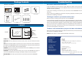
Helpdesk / Technical Support Details
Swann Technical Support
All Countries E-mail: [email protected]
Telephone Helpdesk
AUSTRALIA toll free
USA toll free
1300 138 324
1-800-627-2799
(Su, 2pm-10pm US PT)
(M 9am-5pm AUS ET)
(Tu-F 1am-5pm AUS ET)
(M-Th, 6am-10pm US PT)
(Sa 1am-9am AUS ET)
(F 6am-2pm US PT)
NEW ZEALAND toll free
USA Exchange & Repairs
0800 479 266
1-800-627-2799 (Option 1)
UK
(M-F, 9am-5pm US PT)
0203 027 0979
See http://www.worldtimeserver.com for information on time zones and the
current time in Melbourne, Australia compared to your local time.
Warranty Information
Swann Communications USA Inc.
12636 Clark Street
Santa Fe Springs CA 90670
USA
Swann Communications
Unit 13, 331 Ingles Street,
Port Melbourne Vic 3207
Swann Communications LTD.
Stag Gates House
63/64 The Avenue
SO171XS
United Kingdom
Swann Communications warrants this product against defects in workmanship and material for a period
of one (1) year from it’s original purchase date. You must present your receipt as proof of date of purchase
for warranty validation. Any unit which proves defective during the stated period will be repaired without
charge for parts or labour or replaced at the sole discretion of Swann. The end user is responsible for all
freight charges incurred to send the product to Swann’s repair centres. The end user is responsible for all
shipping costs incurred when shipping from and to any country other than the country of origin.
The warranty does not cover any incidental, accidental or consequential damages arising from the use of
or the inability to use this product. Any costs associated with the fitting or removal of this product by a
tradesman or other person or any other costs associated with its use are the responsibility of the end user.
This warranty applies to the original purchaser of the product only and is not transferable to any third
party. Unauthorized end user or third party modifications to any component or evidence of misuse or
abuse of the device will render all warranties void.
By law some countries do not allow limitations on certain exclusions in this warranty. Where applicable by
local laws, regulations and legal rights will take precedence.
© Swann Communications 2011
FCC Verification
This equipment has been tested and found to comply with the limits for Class B digital device, pursuant
to part 15 of the FCC Rules. These limits are designed to provide reasonable protection against harmful
interference in a residential installation. This equipment generates, uses and can radiate radio frequency
energy and, if not installed and used in accordance with the instructions, may cause harmful interference
to radio or television reception, which can be determined by turning the equipment off and on, the user is
encouraged to try to correct the interference by one or more of the following measures:
Reorient or relocate the receiving antenna
Increase the separation between the equipment and the receiver
• Connect the equipment into an outlet on a circuit different from that to which the receiver is connected
• Consult the dealer or an experienced radio/TV technician for help
WARNING: Modifications not approved by the party responsible for compliance could void user’s authority
to operate the equipment.
8
Doorphone
Video Intercom
with Color LCD Monitor
MDP860C250711E
1
Package Contents
Troubleshooting
What is included
No sound or hard to hear the visitor:
If you are finding it hard to hear the visitor, adjust the volume on the side of the
monitor to make it louder. If this is not sufficient, ask the visitor to stand closer to the
doorbell unit when speaking.
If the visitor is finding it hard to hear you, stand closer to the MONITOR unit when
speaking.
3.5" TFT -LCD monitor
Outdoor camera
& bracket
Monitor bracket
Power adapter
If you are still having difficulties, check that everything is properly installed as per the
Installation and Wiring instructions.
The image is unclear or you cannot see the visitor:
User's
Manual
User's manual
Make sure there is nothing covering the lens on the DOORBELL.
Cable
If you are finding it hard to see your visitor, adjust the brightness or ask the visitor to
stand closer to the doorbell. The doorbell is quite good at displaying people standing
within a few meters of the doorbell in darkness but if you are still having problems,
you may need to install an additional light near the doorbell to illuminate the area.
Screws and others
Layout
Make sure the wiring is attached as per the color coding shown on the back of the
unit and in the diagrams in this manual.
The door is not unlocked when you press the door unlock button:
Screen
Monitor
Talk
Unlock
Warning
Microphone
SCREEN: This is where you view your visitor that the camera sees.
MONITOR: Press this button to connect to the camera and view what the camera
sees.
TALK: Press the TALK button to speak to your visitor. You do not need to hold down
the button. The MONITOR connects to the doorbell for 1 minute. If you need to talk
for longer, you will need to re-press the TALK button.
UNLOCK: If you have attached an electric door strike to the CAMERA, you can unlock
the door by pressing this button.
WARNING: If you get unwanted visitors, you can press this BUTTON to trigger an
alarm at the doorbell that will maybe scare off the visitor or attract attention.
MICROPHONE: The visitor speaks into this to communicate with the MONITOR.
2
Make sure the wiring to the door strike (door latch mechanism) is wired correctly and
that the wires are properly attached.
NOTE: You will require a 12V DC powered doorlock mechanism.
INDOOR MONITOR
Operating Power:
Resolution:
Display size:
Cut-off time:
Operating temperature:
External Dimensions:
DC 13.5V
320x240
3.5” LCD
1 minute (before unit enters standby from call/monitor)
-20°c ~ +50°c / -4°F ~ 122°F
167mm x 98mm x 25mm / 1.0” x 6.6” x 3.9”
OUTDOOR CAMERA
Power supply:
Viewing angle:
Lighting source:
Night vision distance:
Operating temperature:
External dimension:
(supplied by monitor)
52° for the pinhole camera
Infrared LED
9ft / 3m
-20°c ~ +50°c / -4°F ~ 122°F
100mm x 100mm x 22mm / 3.9” x 3.9” x 0.9”
Due to product improvements, specifications may change
without notice.
7
Operation
Layout
A/V out
Chroma Adjust
Brightness Adjust
DOORBELL: The visitor presses the
call button to ring the doorbell
MONITOR: The video of the visitor will be
displayed on the monitor screen. The video
will switch off automatically after one minute.
If it is too dark outside at the doorbell
like at night, the image on the monitor
will appear black and white.
TALK: Touch and release the ‘TALK’
button to talk to the visitor.
MONITOR: When in STANDBY mode, touch
and release the “MONITOR” button to
view a live feed from the camera. The live
feed will switch off automatically after one
minute or you can touch the “MONITOR”
button again to switch off the live feed.
DC 13.5V
Communication
Volume Adjust
The side of the MONITOR has extra controls to help you adjust the MONITOR to suit
your needs.
1.
A/V OUT: This allows you to view or record what the camera captures on an
external device. You can plug a composite AV cable into this port to connect it
to an external VCR, TV or monitor.
2.
CHROMA ADJUST: This adjusts the amount of color in the image seen on the
monitor.
3.
BRIGHTNESS ADJUST: This adjusts the brightness of the image seen on the
monitor.
4.
VOLUME ADJUST: This adjusts the volume that can be heard on the monitor
unit. Turn this up if you are having trouble hearing your visitor or ask them to
speak closer to the camera.
5.
DC 13.5V: This is where you plug the power supply.
If it is too dark outside at the doorbell
like at night, the image on the monitor
will appear black and white.
1.
CAMERA LENS: This is where the image of the
visitor is captured.
2.
MICROPHONE: This is where the visitors speaks
to you.
3.
INFRARED LED LIGHTS: The infra-red LED lights
are what allows the camera to see your visitors at
night. The image will appear black and white.
4.
INDICATOR: This light enables visitors to identify
the outdoor camera at night.
5.
CALL BUTTON (DOORBELL): When the visitor
presses this button, the doorbell rings and the
MONITOR displays the image from the camera.
6.
SPEAKER: This is where the visitor hears you
speak to them from the MONITOR. It also emits
the WARNING alarm.
1
2
WARNING: When viewing a live feed from
the camera, touch the “WARNING’ button
to trigger an alarm at the DOORBELL.
3
Note: The “WARNING” button will not work
in standby mode. You need to be viewing
a live feed by pressing the “MONITOR”
button or by the visitor pressing the
“CALL” button on the DOORBELL.
The “WARNING” alarm will only sound
while you are touching the button and
will only be heard at the DOORBELL.
6
UNLOCK: If the “keylock” option is
fitted, press the ‘UNLOCK’ button to
unlock the door for the visitor.
NOTE: You will need an external
powered 12V DC doorlock.
4
5
6
3
Installation
Wiring diagram
1 4 5 c m̚1 6 0 c m
INSTALL MONITOR
Camera
The ideal installation height of the
MONITOR is about 4.7ft-5.2ft / 145160cm from the ground.
To mount the MONITOR, use the two
screws to secure the mounting bracket to
the wall. Make sure the four metal hooks
are pointing up.
To mount the doorbell / camera,
use the four screws to secure the
mounting bracket to the wall.
Attach the four wires to the doorbell
unit as shown in the wiring diagram
and then mount the doorbell onto
the mounting bracket. Slide it in topedge first to ensure the notches fit
into the guide holes at the top of the
bracket.
4
1 4 5 c m̚1 6 0 c m
INSTALL DOORBELL
Place the MONITOR onto the backplate,
lining up the four hooks with the grooves
in the back of the MONITOR. Then slide
the MONITOR down to secure it onto the
hooks.
To finish, secure the doorbell unit to the
mounting bracket by inserting the screw
through the bottom of the bracket which
holds the doorbell in place.
White
Black
Red
Yellow
White wire for audio
Black wire for ground
Red wire for power supply
Yellow wire for video
Electric lock
1.
POWER: Before installation, make sure the monitor is not plugged in to the
power.
2.
DISTANCE: The distance between the DOORBELL and the MONITOR should be
no more than 10m / approx 32’ since this is how long the connection wire is.
3.
CONNECTION: To ensure everything works correctly, we advise you connect
the MONITOR and DOORBELL together before installation to check you
understand the wiring and that everything works as it should.
Cautions
•
Do not put the doorphone near strong magnetic fields such has televisions.
•
Turn off the power if you are not going to use the doorphone for a long time.
•
Do not use solvents or detergents to clean the doorphone. Do not spray water
directly on the video doorphone. To clean, lightly moisten a cloth with water and
wipe down the device.
•
Do not drop or damage the video doorphone.
•
Do not place either unit in direct sunlight or expose it to rain.
•
Due to high voltage inside the unit and the risk of electric shock, do not
disassemble the unit for any reason. If the unit fails, please refer to the back page
for contact details.
!
WARNING: When fitting the screws into the wall, make sure you are
not inserting them anywhere near electrical wires, including wires
that may be behind the wall. If you are unsure at all, please get a
professional to check first and install the screws for you.
5


![INSTALL GUIDE OEM-AL(RS)-FM6-[ADS-ALCA]-EN](http://vs1.manualzilla.com/store/data/005732796_1-2697dd4b3634b9609d4f115002bbbdbf-150x150.png)