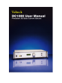
1
www.voltech.com
DC1000
PRECISION DC BIAS CURRENT SOURCE
USER MANUAL
Thank you for choosing the Voltech DC1000. This quality
instrument will give you many years of reliable use. Should you
experience any difficulty during the set up or use of your Voltech
product, please do not hesitate to contact either your local supplier
or one of our main offices .
Voltech Instruments, Inc.
11637 Kelly Road, Suite 306,
Fort Myers, FL 33908
U.S.A.
Tel: +1 (239) 437-0494
Fax: +1 (239) 437-3841
[email protected]
Voltech Instruments, Ltd.
148 Harwell Science and Innovation Campus,
Didcot, OX11 0TR
U.K.
Tel: +44 (0) 1235 861173
Fax: +44 (0) 1235 861174
[email protected]
2
CONTENTS
WARRANTY ............................................................................................................................................................... 5
HEALTH & SAFETY .................................................................................................................................................... 6
SAFETY PRECAUTIONS ............................................................................................................................................ 8
WHAT IS THE DC1000?............................................................................................................................................ 9
WHAT CAN THE DC1000 DO FOR YOU?............................................................................................................... 9
PACKING LIST..........................................................................................................................................................10
GETTING STARTED .................................................................................................................................................11
SAFETY INTERLOCK ................................................................................................................................................13
USING THE DC1000 AND A VOLTECH AT3600 WITH A SAFETY SYSTEM ...................................................................13
USING THE DC1000 WITH AN LCR METER ........................................................................................................16
USING MULTIPLE DC1000S IN PARALLEL ..........................................................................................................17
USING A PC TO CONTROL YOUR DC1000 (S) ....................................................................................................18
USING A PC TO CONTROL YOUR DC1000(S) WITH AN RS232 LCR METER (NOT A VOLTECH AT SERIES
PRODUCT)................................................................................................................................................................19
USING A PC TO CONTROL YOUR DC1000(S) WITH AN IEEE-488 LCR METER (NOT A VOLTECH AT
SERIES PRODUCT)...................................................................................................................................................20
USING THE DC1000 WITH A VOLTECH AT3600 OR ATI(AND OPTIONAL PC) .............................................21
AT COMPENSATION WITH MULTIPLE DC1000S ...........................................................................................22
U SING IR, ILK, HPDC, HPAC TESTS - (HIGH VOLTAGE TESTS).............................................................23
U SING SURG, MAGI, STRW, WATT, VOC TESTS ..................................................................................23
•
LSBX – I NDUCTANCE WITH EXTERNAL BIAS (SERIES CIRCUIT)........................................................................23
•
LPBX – I NDUCTANCE WITH EXTERNAL BIAS (PARALLEL CIRCUIT)...................................................................25
•
ZBX – I MPEDANCE WITH EXTERNAL BIAS......................................................................................................27
RS232 COMMUNICATION ....................................................................................................................................30
RS 232 CONNECTION.............................................................................................................................................30
PINNING.................................................................................................................................................................30
COMMANDS ...........................................................................................................................................................31
•
TURN THE O UTPUT ON OR OFF...................................................................................................................31
•
SET DC1000 OUTPUT CURRENT ..................................................................................................................32
•
GET THE STATUS OF THE UNIT .......................................................................................................................32
•
READ THE SERIAL NUMBER ...........................................................................................................................33
•
GET THE NUMBER OF UNITS ATTACHED ..........................................................................................................33
STATUS NUMBERS.................................................................................................................................................34
CALIBRATION ..........................................................................................................................................................35
ACCESSORIES...........................................................................................................................................................35
PC SOFTWARE .........................................................................................................................................................36
I NSTALLING THE SOFTWARE.....................................................................................................................................36
CONNECTING THE EQUIPMENT ................................................................................................................................36
3
USING THE SOFTWARE ............................................................................................................................................37
SPECIFICATIONS .....................................................................................................................................................43
EMC COMPLIANCE.................................................................................................................................................45
4
WARRANTY
This product is warranted against defect in materials and workmanship for a period of
one year from the date of shipment. During the warranty period, Voltech will, at its
option, either repair or replace products that prove to be defective.
For repair services under warranty, the instrument must be returned to a Voltech
designated service center. Please contact your local supplier for details.
LIMITATION OF WARRANTY
The foregoing warranty shall not apply to defects resulting from unauthorized
modification, misuse, or operation outside the specification of the instrument. No
other warranty is either expressed or implied.
Whilst every care has been taken in compiling the information in this publication,
Voltech cannot accept legal liability for any inaccuracies contained herein. Voltech
has an intensive program of design and development that may alter product
specification, and reserve the right to alter specification without notice and whenever
necessary to ensure optimum performance from its product range.
Because
you are
indirect,
inability
damage.
software is inherently complex, and may not be completely free of errors,
advised to verify your work. In no event will Voltech be liable for direct,
special, incidental or consequential damages arising out of the use of or
to use software or documentation, even if advised of the possibility of such
All right reserved.
No part of this publication may be produced, stored in a retrieval system, or
transmitted in any form, or by means, electronic, mechanical photocopying, recording
or otherwise without prior written permission of Voltech.
© Voltech Instruments, Inc 2010.
Voltech Part Number 98-100 revision 7. August 2013.
5
HEALTH & SAFETY
Electrical devices can constitute a safety hazard. It is the responsibility of the user to
ensure the compliance of the installation with any local acts or bylaws in force. Only
qualified personnel should install this equipment, after reading and understanding this
users manual. These operating instructions should be adhered to. If in any doubt,
please contact your supplier.
DANGER!
Electric Shock Risk
Please Note:
This equipment is supplied under warranty conditions in force at the time of purchase
from your supplier. Contact your supplier for details. Any attempt to disable or
modify the unit will render any warranty agreement invalid.
The contents of this user manual are believed to be accurate at the time of printing.
The manufacturer, however, reserves the right to change the content, product
specification, and performance criteria without notice. No liability is accepted for the
inappropriate, negligent, or incorrect set-up of the instrument by the user, either by
manual or automated means.
6
CHECK YOUR LINE INPUT VOLTAGE SETTING BEFORE CONNECTING TO SUPPLY!
Fig.1
Use a flat-headed screwdriver to pull the fuse drawer out.
Rotate the gray voltage selector to select the correct voltage for your location.
7
SAFETY PRECAUTIONS
•
•
•
There are no user serviceable parts inside the DC1000. Please return the unit
to a Voltech approved service center for any repairs that may be required.
Use fuses only of the type and rating – 4.00A 5X20 T-LAG HI-BREAK (VPN
66-052)
The DC1000 has been constructed in compliance with the requirements of
EN61010-1, Pollution Degree 2, Installation Category II: FOR INDOOR USE
ONLY. This ensures the safety of the instrument and the user when normal
precautions are followed.
8
WHAT IS THE DC1000?
The DC1000 is a DC Bias current source that can generate between 0 and 25A. Up to
ten DC1000’s can simply be joined together in parallel to produce up to 250A.
The DC1000 can be used with almost any LCR meter – making it unique amongst all
DC Bias Current Sources. It can also be used with either the Voltech ‘ATi’ or the
‘AT3600’ transformer testers – these products have specific programs for testing
using the DC1000 (LPBX, LSBX, and ZBX).
WHAT CAN THE DC1000
DO FOR YOU?
The DC1000 is used to characterize wound components that are intended for use in
high current DC power supplies and DC-to-DC converters.
It is used to apply a DC current through the component to be tested, allowing an LCR
meter or Voltech AT-series product to measure the inductance of the component at
that DC current.
Unlike a regular DC power supply; the DC1000 minimizes the load on an LCR meter.
Regular loading would cause gross errors in the measurement of inductors.
Additionally, unlike DC Bias sources from other manufacturers, the Voltech DC1000
can be used with almost any LCR meter.
9
PACKING LIST
When you receive your DC1000, the following accessories will also be in the packing
box with your new instrument. Also given are the Voltech part numbers (VPN), in
case you’d like to order spares.
•
1 x DC1000 CD – Which contains the demo DC1000 PC software and an
electronic version of the user manual. (VPN 88-297)
•
1 x 30A Test Lead set – One yellow and one black, with clips. Each lead is 1.5
meters long. (VPN 78-114)
•
2 x 9-Way Male-Female RS232 Lead – This is for connection between your
DC1000 and a PC or between your DC1000 and another DC1000. (VPN 77-046)
•
1 x Handle Assembly – This includes two handles, and the fixing hardware
needed to attach them to your DC1000 (VPN 74-027)
•
1 x Safety Interlock Override Plug – This can be used in place of a safety
system where there is no risk of dangerous voltages. This is only for use when not
testing with high currents or voltages. We recommend using an approved Safety
System at all times. Please consult your safety officer. (VPN 91-265)
•
1 x Product Registration Card – Please fill this out and return it to Voltech to
help us serve you better. (VPN 86-203)
•
1 x Power Cord (VPN 91-019L)
If there is anything missing from this list when you first unpack your new DC1000,
then please contact your supplier for an immediate replacement.
10
GETTING STARTED
The DC1000 is designed with ease of use and speed of testing in mind. Following is a
description of the functions on both the front and rear panels of the DC1000, to help
you familiarize yourself with the basic operation of the instrument.
FRONT PANEL DESCRIPTION
Fig.2
1) Power Switch – Used to turn power to the instrument ON or OFF.
2) Output Terminals – 4mm safety sockets, for connection of the supplied 30A
test leads.
3) Display – 4-character display to indicate the output current in Amps.
4) Compliance LED – Lights up to indicate an error. The display will indicate
the error number. See the “Status Numbers” section in this manual for details.
5) Rotary Dial – Rotates to set the output current
6) Output Enable Button/LED – Momentary button used to enable or disable
the output current. A green LED indicates the status of the output. The LED
lights to indicate that the output is turned on.
7) Remote Button – Momentary button used to put the instrument into ‘Remote’
mode – in which another DC1000 or a PC can control it. A yellow LED
indicates that ‘Remote’ mode is turned on.
11
REAR PANEL DESCRIPTION
Fig.3
1) RS232 IN – Connects either to a PC or to the RS232 OUT port of the
DC1000 closest to the controlling DC1000 or a Voltech AT instrument.
2) RS232 OUT – Connects to the RS232 IN port of another DC1000, in order to
control its functionality, or connects to another DC1000, or any LCR meter
other that a Voltech AT series product.
3) Fan Outlet – When outputting high currents from the DC1000 for an
extended period of time, high temperatures can be produced. Please keep this
air outlet clear of obstruction to allow the instrument to automatically regulate
its internal temperature.
4) Safety Interlock IN – Connects to a safety device, such as a light curtain.
When the connection is broken the DC1000 ceases to produce any current.
5) Safety Interlock OUT – Connects to another DC1000’s Safety Interlock IN
port. If you are using more than one DC1000 in parallel, then a single safety
device can control each of the units in the chain.
6) Power Entry Module – Connect the power outlet to this socket. Contained
within the module are two fuses, which should always be replaced when
necessary with the same type and rating (4.00A 5X20 T-LAG HI-BREAK).
There is also a voltage selector, which should always be checked, and set, if
necessary, to the correct voltage for your location.
12
SAFETY INTERLOCK
For the DC1000 to produce any current, a safety system is required.
The DC1000 can be used with and produces high currents; therefore, Voltech
recommends that your always use a safety system when using your DC1000.
Consult with your company’s safety officer prior to using the DC1000.
Your safety system should not allow the operator or near-by workers to touch any
dangerous part during testing.
A single safety device can control all the DC1000s in your chain. Fig. 24 indicates the
required connections to connect either a single DC1000 or multiple instruments to
your safety device.
Fig.24
Please take care not to insert the safety interlock cable into the RS232 port on the rear
of the DC1000. Doing so could damage your instrument.
USING THE DC1000 AND A VOLTECH AT3600 WITH A SAFETY SYSTEM
When using your DC1000(s) with a Voltech AT3600, the AT should be placed at the
end of the chain. Connect the Safety Interlock OUT of the DC1000 furthest removed
from your safety device to the Safety Interlock port of the AT3600. Fig. 16 shows this
connection.
13
Fig. 25
For optimum safety, ease of use and test speed, Voltech recommends the use of a
safety light curtain.
This provides a ‘light curtain’ of infrared beams positioned in front of the test
environment. Once the operator has removed his hand, the light curtain can signal that
the situation is safe within a few tens of milliseconds. However, if the operator breaks
the light curtain during testing, the safety system will open the safety interlocks (also
within a few tens of milliseconds), so that the DC1000 output will cease.
Voltech can provide a cable for connection between a light curtain and the DC1000 or
AT transformer tester. The cable has been optimized for use with the ‘Banner’ safety
light curtain described below, but safety light curtains from other manufacturers may
also be suitable.
To construct a complete safety system you will need:
• Voltech Safety Interlock Harness provided with your DC1000.
14
•
•
•
•
•
•
Voltech Safety Interlock Cable
Banner ‘Micro-Screen’ safety light curtain
1 x USCD-1T2 Metal Box Controller
1 x USE2424YI Yellow Emitter 610mm high with 150mm to 9m range.
1 x USR2424YI Yellow Receiver 610mm high with 150mm to 9m
range.
Source: http://www.banner.com/
Methods to restrict access to the back of the working area
NOTE: The Banner part numbers were correct in 2005. You are strongly advised to
consult with your safety system supplier before making purchase decisions. Similar
safety systems are available from many other manufacturers and may be suitable.
Your DC1000 shipped with a Safety Interlock Override Plug, which can be inserted
into the Safety Interlock IN port in the place of a safety device. DO NOT USE
THIS DEVICE WITH DANGEROUS CURRENTS OR VOLTAGES!
15
USING THE DC1000
WITH AN LCR METER
The powerful design of the DC1000 allows it to be used with almost any
manufacturer’s LCR meter. Using the test leads that were supplied with your DC1000
and with your LCR meter, it is fast and easy to setup your environment for testing an
inductor.
A) Be sure that the power is off to your Voltech DC1000.
B) Make all the connections indicated in fig.4.
C) Power up your DC1000, and turn the output on, making sure that the current
output is set to zero.
D) Perform compensation on your LCR meter.
E) Turn the DC1000 output off.
F) Using the rotary encoder set your DC1000 output to the desired current.
G) Turn the DC1000 output on.
H) Adjustments can be made to the DC1000 current while the output is enabled,
using the rotary encoder.
Fig. 4
Be sure to connect the HI side of your LCR meter to the same side of the inductor to
which the HI side of your DC1000 is attached, and use the opposite side of the
inductor to connect the LO sides of both the DC1000 and the LCR meter.
LCR COMPENSATION WITH A SINGLE DC1000
When compensating your LCR meter for use with the DC1000, always set the current
to ‘0.00’ and turn the output ON.
16
USING MULTIPLE DC1000S IN PARALLEL
You can generate up to 250A as a maximum by connecting up to ten DC1000s
together in parallel. Either the first DC1000, or a PC or a Voltech AT3600 or ATi can
be used to control all the other DC1000s in the chain – automatically adjusting their
output current to allow you to easily achieve the results you require.
Everything you need to hookup multiple DC1000s is provided with the units
themselves. Fig.5 illustrates the connections required.
Fig.5
Be sure to connect the HI side of your LCR meter to the same side of the inductor to
which the HI sides of your DC1000s are attached, and use the opposite side of the
inductor to connect the LO sides of both the DC1000s and the LCR meter.
Connect the 9-Way RS232 cable between the RS232 OUT of the first DC1000 in
your chain and the RS232 IN of the second DC1000, using the cable provided with
your DC1000. Then, if you have more than two DC1000’s, connect the RS232 OUT
of the second DC1000 in your chain to the RS232 IN of the third. Follow the same
pattern for any remaining DC1000’s you wish to connect together in parallel.
Always connect directly from EACH DC1000 in your chain to the inductor. NEVER
daisy chain the outputs of multiple DC1000’s. The accumulated current could exceed
the rating for the supplied cable, and cause fire and injury.
LCR COMPENSATION WITH M ULTIPLE DC1000S
When compensating your LCR meter for use with the DC1000s, always set each
DC1000’s current to ‘0.00’ and turn the output ON at each unit.
17
USING A PC
TO CONTROL YOUR DC1000 (S)
To use a PC to just control your DC1000s, but not controlling an LCR meter at the
same time, follow the setup in Fig.6.
Fig. 6
Connect your computer’s RS232 port to the RS232 IN port of the first DC1000 in
your chain (‘DC1000 # 1’), using a 9-way male to 9-way female null modem cable
(see ‘Accessories’ section of this user manual).
Connect the RS232 IN port of the next DC1000 in your chain to the previous
DC1000’s RS232 OUT.
NOTE: See the RS232 communications section for information on USB to RS232
converters.
18
USING A PC TO CONTROL YOUR DC1000(S) WITH
AN RS232 LCR METER (NOT A VOLTECH AT
SERIES PRODUCT)
To use your PC to control your DC1000s, and an LCR meter with RS232
communications capability, follow the setup in Fig.7.
Fig.7
Connect your computer’s RS232 port to the RS232 IN port of the first DC1000 in
your chain (‘DC1000 # 1’), using a 9-way male to 9-way female null modem cable
(see ‘Accessories’ section of this user manual).
When using an LCR meter with RS232 communications capability, connect the
RS232 port of the LCR meter to the RS232 OUT port of the last DC1000 ‘(DC1000 #
2’ in the Fig. 7) in your chain, using a null modem cable (see the Accessories section
of this user manual for details on a null modem cable available from Voltech, but
please note, that the type of cable required will depend on the type of RS232
connector on your LCR meter. See the RS232 Communications - Pinning section of
this user manual for details if a custom cable is required).
NOTE: See the RS232 communications section for information on USB to RS232
converters.
19
USING A PC TO CONTROL YOUR DC1000(S) WITH
AN IEEE-488 LCR METER (NOT A VOLTECH AT
SERIES PRODUCT)
To use your PC to control your DC1000s, and an LCR meter with IEEE-488
communications capability, follow the setup in Fig.8.
Fig.8
Connect your computer’s RS232 port to the RS232 IN port of the first DC1000 in
your chain (‘DC1000 # 1’), using a 9-way male to 9-way female null modem cable
(see ‘Accessories’ section of this user manual).
When using an LCR meter without RS232 communications capability, the PC you are
using must have both an RS232 port (to control the DC1000s) and an IEEE-488 port
(to control the LCR meter directly). Connect the PC directly to the IEEE port of the
LCR meter, as illustrated in Fig. 8.
NOTE: See the RS232 communications section for information on USB to RS232
converters.
20
USING THE DC1000 WITH A VOLTECH AT3600
OR AT I(AND OPTIONAL PC)
Fig. 9
Connect the Auxiliary port on your Voltech ATi or AT3600 to the RS232 IN port on
your DC1000 using the 9-way male to 9-way female straight-through RS232 cable
that was provided with your DC1000.
NOTE: See the RS232 communications section for information on USB to RS232
converters.
If you wish to use a PC to control your AT36 when you have a DC1000 hooked up to
the auxiliary port, attach the PC’s RS232 connector to the DC1000’s RS232 OUT port
using the 9-way male to 9-way male straight-through RS232 cable that was provided
with your AT product. This setup will work with any communications software you
use (e.g. Voltech AT Editor Software, or Voltech DC1000 PC Software).
21
When using the DC1000 PC Software, which was provided with your DC1000, the
HI side of the DC1000 output, and of the inductor under test, should be connected to
node 15 of the AT fixture being used, and the LO side should be connected to node
13. There are standard fixtures available from Voltech that provide connection to
these nodes, for example the LCR Fixture (VPN 91-227). See the “Fixtures” chapter
of your AT manual for information regarding standard, and custom, fixture solutions.
To use any Voltech software with an AT series product, specific DC1000 tests
(LPBX, LSBX, and ZBX) must be installed on the AT being used. As with all
Voltech AT tests, these are provided on a per AT basis – so no matter how many
DC1000s you have connected, one test purchase will cover all DC1000s attached to
your AT. Contact your local Voltech supplier for details on attaining these tests.
AT COMPENSATION WITH M ULTIPLE DC1000S
When compensating your Voltech AT product for use with the DC1000(s):
1) Measure the open circuit inductance without the DC1000s connected, by
performing “AT measure” with the Editor. Note this inductance value.
2) Connect your DC1000(s) to the device under test, with all output turned on,
and current set to zero.
3) Subtract the inductance value now from the inductance value taken without the
DC1000(s) connected. Use this value as the negative offset when running an
AT program.
22
USING IR, ILK, HPDC, HPAC TESTS - (HIGH VOLTAGE TESTS )
Voltech AT3600 or ATi programs that include any of these tests should be connected
such that the LO winding is the one that is connected to the DC1000 output. Fig.10
below illustrates this setup. INCORRECT CONNECTIONS TO THE DC1000
MAY CAUSE DAMAGE.
Fig.10
USING SURG, MAGI, STRW, WATT, VOC TESTS
These tests must not be used on any winding on a component to which a DC1000
is attached. The surge voltage will effectively test the DC1000, not the winding, and
this may cause damage to your DC1000.
AT TESTS
•
LSBX – INDUCTANCE WITH EXTERNAL BIAS (S ERIES CIRCUIT)
The inductance of a transformer winding while an external bias current is
flowing through it may be tested using series or parallel equivalent circuit
models. Initially the DC bias current is set up and allowed to stabilize. An AC
voltage is applied across the selected winding; the voltage across, and current
through, the winding is then measured using harmonic analysis. The measured
voltage is divided by the current to obtain a complex impedance and the
inductance is calculated.
23
On selecting ‘LSBX Inductance with External Bias (Series Circuit)’ or ‘LPBX
Inductance with External Bias (Parallel Circuit) from the ‘Available Tests’
window, a dialogue box will be displayed.
Fig.11
To program the test:
1. Enter the signal, frequency and bias current required for the test.
Note that the signal is normally entered as a voltage by selecting the ‘mV’ or
‘V’ button; but you may optionally enter it as a current by selecting the ‘mA’
button. (If in doubt refer to the ‘Test Conditions’ chapter of your AT user
manual.
Note also that the measure button may be used here, as outlined in your AT
user manual, with the combinations of test parameter specification shown in
the following table:
Signal
Frequency
Bias
Option 1
Specified voltage
Specified
Specified
Option 2
Specified current
Specified
Specified
Option 3
Auto
Specified
Specified
Option 4
Auto
Auto
Specified
2. Select (mouse click the button) the integration time you require.
24
‘Medium’ is the default setting. ‘Long’ will give you more stable readings
(for tighter limits) at the expense of test time, and ‘Short’ will test at the
maximum speed, but may give slightly noisier readings.
3. Enter the terminal names between which the inductance will be measured.
By pulling down the menu along side the fill-in box, you may select the
high and low terminals for each test.
4. Select (mouse click the button) the type of limits you require, and enter the
values.
%
Enter a nominal value and then the limits as negative and
positive values.
><
Enter minimum and maximum values.
>
Enter just a minimum value.
<
Enter just a maximum value.
5. Select OK. The test specification will then be displayed in the program
window.
•
LPBX – INDUCTANCE WITH EXTERNAL BIAS (P ARALLEL CIRCUIT)
The inductance of a transformer winding while an external bias current is
flowing through it may be tested using series or parallel equivalent circuit
models. Initially the DC bias current is set up and allowed to stabilize. An AC
voltage is applied across the selected winding; the voltage across and current
through the winding are then measured using harmonic analysis. The
measured voltage is divided by the current to obtain a complex impedance and
the inductance is calculated.
On selecting ‘LSBX Inductance with External Bias (Series Circuit)’ or ‘LPBX
Inductance with External Bias (Parallel Circuit) from the ‘Available Tests’
window, a dialogue box will be displayed.
25
Fig.12
To program the test:
6. Enter the signal, frequency and bias current required for the test.
Note that the signal is normally entered as a voltage by selecting the ‘mV’ or
‘V’ button; but you may optionally enter it as a current by selecting the ‘mA’
button. (If in doubt refer to the ‘Test Conditions’ chapter of your AT user
manual.
Note also that the measure button may be used here, as outlined in your AT
user manual, with the combinations of test parameter specification shown in
the following table:
Signal
Frequency
Bias
Option 1
Specified voltage
Specified
Specified
Option 2
Specified current
Specified
Specified
Option 3
Auto
Specified
Specified
Option 4
Auto
Auto
Specified
7. Select (mouse click the button) the integration time you require.
‘Medium’ is the default setting. ‘Long’ will give you more stable readings
(for tighter limits) at the expense of test time, and ‘Short’ will test at the
maximum speed, but may give slightly noisier readings.
26
8. Enter the terminal names between which the inductance will be measured.
By pulling down the menu along side the fill-in box, you may select the
high and low terminals for each test.
9. Select (mouse click the button) the type of limits you require, and enter the
values.
%
Enter a nominal value and then the limits as negative and
positive values.
><
Enter minimum and maximum values.
>
Enter just a minimum value.
<
Enter just a maximum value.
10. Select OK. The test specification will then be displayed in the program
window.
•
ZBX – IMPEDANCE WITH EXTERNAL BIAS
The Winding Impedance with External Bias test measures the impedance of a
selected winding while applying a DC current from the DC1000 through the
winding. An AC voltage is also applied across the winding from the AT.
This test can be used with inductors to measure the change in impedance with
a bias current.
On selecting “ZBX Impedance with External Bias” from the ‘available tests’
window, the following dialog box is displayed:
27
Fig. 13
To program the test:
1. Enter the value of a voltage (or current) for the signal and the required
frequency of the test.
Also enter the bias current you would like to apply.
Please note that the Measure button may be used here. For information,
refer to the ‘Test Program Editor’ of your AT manual.
2. Select the integration time required. ‘Medium’ is the default setting.
‘Long’ will give more stable readings (for tighter limits) at the expense of
time, and ‘Short’ will test at the maximum speed, but may give slightly
noisier readings.
3. Enter the terminal names between which the impedance is to be measured.
4. Set the impedance limits.
+/-
Enter a nominal value and then the limits as negative and
positive values.
28
><
Enter minimum and maximum values.
>
Enter just a minimum value.
<
Enter just a maximum value.
5. Select OK. The test specification will then be displayed in the program
window.
29
RS232 Communication
RS 232 connection
Many PCs today do not come with an RS232 as standard. To add an RS232 port to
your PC, Voltech recommend the use of one of the following USB to RS232
converters:
1. USB Gear (www.usbgrear.com) part number USBG-RS232-F12.
2. Cables to Go (www.cablestogo.com) part number 26886.
Both of these cables have been verified with the DC1000 software.
Pinning
The pinning of the 2 RS232 ports is as follows:
RS232 IN
TX = PIN 3
RX = PIN 2
CTS = PIN 8
RTS = PIN 7
0V = PIN 5
RS232 OUT
TX = PIN 2
RX = PIN 3
CTS = PIN 7
RTS = PIN 8
0V = PIN 5
30
RS232 IN (Female)
RS232 OUT (Male)
Commands
For your convenience, listed below are the RS232 commands you can use to control
the DC1000 remotely. The baud rate that you should use to communicate with the
DC1000 is 9600, with 8 data bits, parity is none, 1 stop bit, and there is hardware flow
control.
Please note that depending on the software that you are using to send these commands
to the DC1000, the manner in which carriage returns and line feeds are sent differs. In
the below commands <cr> and <lf> are used to indicate the need for a carriage return,
or a line feed respectively. A line feed can be sent via a terminal emulator by pressing
<ctrl> and j simultaneously.
•
TURN THE OUTPUT ON OR OFF
Command
“D_POWER,x <lf>”
This command will act in the same way as pressing the on/off switch on the
front panel to turn the unit off.
If x = 0, then the power is turned off.
If x = 1, then the power is turned on.
Messages returned
The following messages will be returned:
Within 100ms, an attached unit will respond with:
31
“D_COUNT,xx <cr> <lf>”
where xx is the number of units in the chain.
Within 2 seconds, the unit will respond with:
“D_STAT,0,result <cr> <lf>”” where result is a single integer indicating the
status of the unit and any other unit attached.
If everything is OK, 0 or 1 will be returned. If not, then a status number will
be returned.
•
SET DC1000 OUTPUT CURRENT
Command
“D_SET,level <lf>”, where level is the demand in milli-Amps and can range
from 100 to 25000. If multiple units are connected together, then the same
current will be sent to each unit.
Messages returned
The following messages will be returned:
Within 100ms, an attached unit will respond with:
“D_COUNT,xx <cr> <lf>”
where xx is the number of units in the chain.
Within 2 seconds, the unit will respond with:
“D_STAT,0,status <cr> <lf>” where status is a single integer indicating the
status of the unit and any other unit attached.
If everything is OK, 0 or 1 will be returned. If not, then a status number will
be returned.
•
GET THE STATUS OF THE UNIT
Command
“D_STAT? <lf>”
This command will return the status of the attached DC Bias unit
32
Messages returned
The following messages will be returned:
The unit will respond with:
“D_STAT,0,status <cr> <lf>” where status is a single integer indicating the
status of the unit and any other unit attached.
If everything is OK, 0 or 1 will be returned. If not, then a status number will
be returned.
•
READ THE SERIAL NUMBER
Command
“D_SER? <lf> ”
Messages returned
The following will be returned
Serialnumber <cr> <lf> where serialnumber is the serial number of the
DC1000 (Serial number returned will always be 12 digits, if the queried unit’s
serial number has less characters, then spaces will fill it out to 12.
•
GET THE NUMBER OF UNITS ATTACHED
Command
“D_COUNT? <lf>
Messages returned
The following will be returned within 5 seconds
“D_COUNT,xx <cr> <lf>” where xx is the number of DC1000s in the chain.
33
STATUS NUMBERS
The DC1000 will return status numbers, either on the front panel display if there is an
error, or via RS232 if it is requested. If the status is an error that is indicated in fig. 14
as needing to turn off the output, then in order to clear the error, and try again, the
output must first be turned off. If multiple errors occur, either on the same unit, or on
other units in the chain, then a combination of the status numbers will be returned.
Status
0
1
2
4
8
16
32
64
128
256
Meaning
Off
On and all OK
Compliance circuit error
Trim error
Safety interlock error
Temperature error
Ramp Up
Ramp Down
Current ADC Over range
Compliance circuit error open circuit
Turn Off Output
ü
ü
ü
ü
ü
ü
ü
Fig. 14
34
CALIBRATION
Voltech recommends that the DC1000 should be calibrated and verified once per year.
You may return the instrument to any Voltech authorized service center for fast and
accurate calibration. Contact your nearest sales office for information on returning a
product for service.
ACCESSORIES
If you require any cables, safety override plugs or fuses (VPN 66-052), in addition to
those supplied with your DC1000, please contact your local Voltech supplier. The
part numbers for the parts supplied with your unit are given in the section ‘Packing
List’ in this manual.
The Voltech part number for the RS232 cable supplied with AT products that you can
use to interface with the DC1000 is 77-015.
The Voltech part number for the Null Modem cable for PC software connectivity is
77-045. A similar cable is also available from www.cablewholesale.com, p/n 10D120206. This part number was correct at time of publication of this manual.
35
PC SOFTWARE
To support the measurement of inductors under different DC load currents, Voltech
has developed a simple PC software application that will enable you to use your
DC1000 and an LCR meter to make inductance measurements with different DC bias
current levels. The results can be displayed graphically on the screen as well as saved
to a file.
Installing the Software
The software is available from Voltech’s web site (www.voltech.com) in the support
section. You should download the “DC1000.zip” file and save this to your PC.
Once downloaded, extract the contents to a temporary folder. The “DC1000
Software.zip” file contains both the PC application and the National Instruments
VISA runtime engine, which is required to run the PC software.
To install the software, run “setup.exe” from the folder to which the “DC1000.zip”
files were extracted. Follow the on screen instructions.
To install the National Instruments run time VISA, run “visa410runtime.exe” and
follow the on screen instructions.
Connecting the Equipment
The DC1000 software currently supports the control of both the DC1000 bias unit,
Voltech’s AT3600 and ATi and an HP 4284A LCR meter. Follow the instructions
earlier in this manual for making the appropriate connections.
The software supports the control of an LCR meter via a GPIB connection. The
DC1000 software works with all National Instruments GPIB cards. Voltech
recommends the National Instruments USB to GPIB converter part number GPIBUSB-HS.
For information on RS232 support, see the RS232 communications section for
information on USB to RS232 converters.
36
Using the Software
To run the software, Click Start -> All Programs -> DC1000 and then select DC1000.
Step 1: Select the LCR meter
Figure 15
Under Test Set-Up, you can select an LCR meter that will be used to make the
inductance measurement. Select the LCR meter than you want to use. In figure 15
above, an HP4284A meter has been selected.
Step 2: Set up communications
Figure 16
Next, set up the communications. If you have selected an AT3600 or an ATi, there
will be only one connection item to fill in. If you have selected to control an LCR
meter via GPIB then the device will need to be selected. In the example shown in
figure 16, the HP4284 is on GPIB address 17 and the DC1000 is on comm. port 6.
You can see what comms ports are available by opening the Device Manager on your
PC.
To test that the communications are working correctly, click on “Test Comms”. The
screen shown in figure 17 will appear. To run the communications test, click on the
“Identify Connected Items” button. If the comms have been set up correctly, then the
37
identifier string will be displayed. If comms are not working, then an error message
will be displayed with information on what may be wrong.
Figure 17
Clicking on the Saturation curve tab while in Comms Set-up with the “Test Comms”
button pressed, will return you straight back to the screen shown in figure 17.
Step 3: Set up the bias current
Next, the minimum and maximum DC current needs to be specified along with the
number of steps and the number of bias units attached. The increment of each step
will be the difference between the maximum and minimum current, divided by the
number of steps minus 1.
38
Figure 18
For example, if figure 18, the step size would be 0.1A.
Step 4: Set up the inductance measurement
Next, set up the inductance test voltage and frequency. Also, if the LCR meter is an
AT3600 or an ATi, you will need to specify the high and low node of the top matrix
between which the inductance measurement will be made. For the ATi, if you are
using an LCR fixture, then nodes 13 and 15 should be used.
Step 5: Run the test
Before you run the test, you need to decide whether you want to save the results to a
file. This can be done by checking the box under “Save Results” and then selecting a
destination location and file. The results will be saved in Excel format. Also, the
results will be continuously appended until the “Save Results” is set to off.
Figure 19
The test is run by clicking on the “Begin” button.
39
If you click the “Begin” button with no or inappropriate communications set up, you
will receive an error message and the application will stop. The application can be restarted by clicking on the right-facing Run arrow at the top left.
Step 6: View the results
As the test runs, the inductance measurements and the DC current will be added to
each step in the results grid. An example is shown in figure 20 below.
Figure 20
Once the test has finished, you can look at a saturation graph. An example is shown
in figure 21.
40
Figure 21
The appearance and the position of the cursor can be controlled by using the buttons
to the right of the inductance value.
To enable or disable cursor movement, press
. To change the appearance of the
cursor, press . The cursor can be either allowed to move freely, or locked to the
plot. The
button controls this. Finally, the cursor can be moved around using the
arrow buttons (
).
To clear the results from both the results window and the graph window, click on the
“Clear Results” button. This will also allow you to change the inductance scaling.
Step 7: Save the results to an Image
Figure 22
The results from the test can be save to an Excel file by clicking check box under
“Save results” and then selecting the destination file. Also, a screen shot of the
41
DC1000 software can be saved to an HTML file by selecting the name and destination
of the file and clicking on “Save html”.
42
SPECIFICATIONS
Output Capability: 0 to 25A; in 10mA steps.
Accuracy on Supplied Current: ±0.5% of reading ±25mA.
Compliance voltage: 5V pk.
Affect of the DC1000 on Inductance Readings
The affect the DC1000 has on an inductance reading is dependant on the test Voltage and frequency.
Fig. 17 should be used to determine the affect for a particular test.
Fig. 23
Example:
Measuring the inductance of a 2µH inductor at 0.2V, 100kHz:
Z = 1.2566O
∴@ 0.2V, i = 159.155mA
From fig. 23, the error current = 0.45µA/mV @ 100kHz
Which, for a signal of 0.2V = 90µA
∴ Error in measurement = 90µA / 159.155mA = 0.057%
Environment
Temperature: +5° to +40°C operating
Humidity: 10% to 80% RH non-condensing
Power Supply to Case: 2.9kV DC for 1 minute.
Power Requirement: 100-125V / 200-250V AC 48-65Hz. 400VA Max.
43
Supply Voltage
Input Voltage: 100-125V / 200-250V AC 48-65Hz
Input Power: 400VA Max.
Fuse:
4AT
Environment
Temperature:
Humidity:
+5° to 40°C operating
10% to 80% RH non-condensing.
Dimensions
Height:
Width:
Length:
Weight:
88mm
475mm
255mm
10kg
Interfaces
RS232 connection to ATi or AT3600 Transformer Testers
Safety Interlock
Protection for operators from back EMF when interlock connected to safety cage.
Variable Speed Cooling Fan
Runs fan at variable speed dependent on load and temperature for minimal noise.
44
EMC COMPLIANCE
The DC1000 complies with the limits of BS EN 55022 Class A.
DECLARATION OF CONFORMITY
Manufacturer's Name
Voltech Instruments, Inc.
Manufacturer's Address
11637 Kelly Road
Fort Myers FL
USA
declares, that the product
Product Name:
Precision DC Bias Current Source
Model Number:
DC1000
conforms to the following Product Specifications
Safety:
BS EN 61010 (1993)
EMC:
BS EN 55022 (1995): Class A
BS EN 50082-2 (1992)
Supplementary Information:
The product herewith complies with the requirements of
the EMC Directives 89/336/EEC and 92/31/EEC and the
Low Voltage Directive 73/23/EEC
Signed for on behalf of Voltech Instruments, Inc.
22 July 2005
Voltech Instruments, Inc. has an intensive program of
design and development that may alter product
specification.
Voltech Instruments, Inc. reserves the right to change
the product specification at any time, and without
notice.
No part of this publication may be produced or
transmitted in any form, or by any means, electronic,
mechanical, photocopying, recording or otherwise,
without prior permission of Voltech Instruments, Inc.
© Voltech Instruments, Inc. 2010.
45