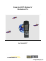
Download Integrated GPS Module for Workabout Pro
Transcript
Integrated GPS Module for Workabout Pro DATASHEET Title Integrated GPS Module for Workabout Pro Doc Type Datasheet Doc Id TS A00329 Revision Date Name Status/Comment A00 10/10/07 F.DEBULOIS M.ARNAUD Initial Version A01 08/11/07 F.DEBULOIS P/N Update A02 16/01/08 M.ARNAUD Setup Documentation Update Specifications are subject to change without notice Psion Teklogix™ is a trademark of Psion Teklogix Inc. Other product names mentioned in this document may be trademarks of Psion Teklogix Inc. or trademarks or registered trademarks of other hardware, software, or service providers and are used herein for identification purposes only. Table of Content I. Preface...........................................................................................................................................5 I.1. Scope .................................................................................................................................................. 5 I.2. Terminology ....................................................................................................................................... 5 I.3. Reference document ........................................................................................................................... 5 II. Module presentation ....................................................................................................................6 II.1. Form factor – Ordering information.................................................................................................. 6 II.2. Compatibility..................................................................................................................................... 6 II.3. Connectivity ...................................................................................................................................... 6 II.4. GPS features ...................................................................................................................................... 7 III. Module Specification .................................................................................................................8 III.1. Block Diagram ................................................................................................................................. 8 III.2. Description....................................................................................................................................... 9 III.2.1. GPS antenna ............................................................................................................................................. 9 III.2.2. Power management................................................................................................................................... 9 III.2.3. Backup battery.......................................................................................................................................... 9 III.2.4. Communication setup ............................................................................................................................... 9 III.3. GPS functions ................................................................................................................................ 10 III.4. Electrical specification................................................................................................................... 10 III.5. Connector Pinout............................................................................................................................ 11 III.5.1. J1 : scanner connector............................................................................................................................. 11 III.5.2. J2 : USB connector ................................................................................................................................. 11 III.5.3. Configuration switches ........................................................................................................................... 11 IV. Quick Start User Guide ............................................................................................................13 IV.1. Hardware installation..................................................................................................................... 13 IV.1.1. Module configuration ............................................................................................................................. 13 IV.1.2. On a Workabout Pro G1 ......................................................................................................................... 14 IV.1.3. On a Workabout Pro G2 via flex cable................................................................................................... 16 IV.1.4. On a Workabout Pro G2 via 4-way cable............................................................................................... 17 IV.2. Demo Software installation ........................................................................................................... 18 IV.2.1. GPS module installation ......................................................................................................................... 18 IV.2.2. Software installation............................................................................................................................... 18 IV.2.3. Software configuration ........................................................................................................................... 18 V. Developer’s guide......................................................................................................................19 V.1. Power management ......................................................................................................................... 19 V.1.1. GPS on scanner flex cable ....................................................................................................................... 19 V.1.2. GPS on expansion USB connector .......................................................................................................... 20 V.1.3. WORKABOUT PRO USB hub............................................................................................................... 20 V.2. USB driver installation.................................................................................................................... 21 V.3. Connection settings ......................................................................................................................... 21 V.3.1. GPS with serial communication mode..................................................................................................... 21 V.3.2. GPS with USB communication mode...................................................................................................... 21 VI. Maintenance .............................................................................................................................22 VI.1. Endcap assembly............................................................................................................................ 22 VI.2. Communication Setup.................................................................................................................... 24 VI.2.1. USB Link................................................................................................................................................ 24 VI.2.2. Serial Link .............................................................................................................................................. 25 Integrated GPS Module – Datasheet TS-A00329-A02 Page 4/25 I. Preface I.1. Scope This document gives all the information necessary for users to evaluate and use the integrated GPS module for WORKABOUT PRO hand-held computers. I.2. Terminology API GPS NMEA 0183 UBX Protocol Workabout PRO Application Programming Interface Global Positioning System ASCII based standard data communication protocol used by GPS receivers A proprietary binary protocol used by the ANTARISTM GPS technology WorkAbout Pro Hand-held computer from PSION Teklogix I.3. Reference document Document ANTARIS ® 4 GPS Modules Datasheet Integrated GPS Module – Datasheet TS-A00329-A02 Reference GPS.G4-MS4-06143-1 Version Date 1 05/25/2007 Page 5/25 II. Module presentation II.1. Form factor – Ordering information The integrated GPS module is made of a GPS receiver board embedded in the multipurpose endcap: - P/N 1051350 for the GSM compatible version - P/N 1051355 for the stylus version Plastic end cap 4 ways cable. Scanner flex electronic board II.2. Compatibility The integrated GPS module can be used with WORKABOUT PRO G1 or G2 computers, and is compatible with short and long version. II.3. Connectivity The integrated GPS module can be connected to the WORKAB OUT PRO motherboard: - Using the scanner flex cable; in that case, the connection can be configured as a serial or USB connection, and the original flex cable is replaced by a 6 inch flex cable. - Using a 4-way USB cable, on WORKABOUT G2 computer. The module is delivered with both connection options (6 inch flex cable and 4-way cable). The user has to remove the unneeded one. Integrated GPS Module – Datasheet TS-A00329-A02 Page 6/25 II.4. GPS features The uBlox GPS module is used. Its main features are: - 1 USB and 1 UART port - 4 Hz position update rate - 16 channel ANTARIS 4 positioning engine - SuperSense® Indoor GPS - A-GPS and Autonomous GPS operation, AssistNow™ ready - Supports DGPS, WAAS, EGNOS and MSAS - Supports NMEA, UBX and RTCM protocols - Power saving modes Integrated GPS Module – Datasheet TS-A00329-A02 Page 7/25 III. Module Specification III.1. Block Diagram USB Connector 25x25mm Patch antenna Scanner Connector USB DIP Switches Serial UBLOX ANTARIS 4 LEA-4H GPS Module Power management Backup battery GPS Module Block diagram Configuration switches scanner connector 4 way conn. GPS Module Electronic board Components side Integrated GPS Module – Datasheet TS-A00329-A02 Page 8/25 III.2. Description III.2.1. GPS antenna The GPS module has an embedded passive patch ceramic antenna. No external antenna connection is required. III.2.2. Power management Power for the board comes from: - +5V_BAR if scanner flex cable is used - VDD_USB (5V) if 4-way cable is used. The board is turned off: - when connected to scanner flex cable: o if +5V_BAR is turned off o if Power_enable pin is driven low. - When connected to 4-way cable o If VDD_USB is turned off Refer to chapter V.1 for information on how software can manage the power to the board. III.2.3. Backup battery A backup battery allows the UBLOX LEA-4H module to recover from power down mode with either a Hotstart or a Warmstart (depending on the duration of VCC outage) and to maintain the configuration settings. The capacity of the backup battery allows a VCC outage of 30 hours. III.2.4. Communication setup The communication link with the module can be set up with either serial or USB link. Refer to chapter VI.2 to know how to change the module configuration. In both cases, the link seen by the operating system of the computer is a serial link. Integrated GPS Module – Datasheet TS-A00329-A02 Page 9/25 III.3. GPS functions For details on GPS functions, please refer to ANTARIS® 4 GPS Modules Datasheet Ref. GPS.G4-MS4-06143-1. III.4. Electrical specification Absolute Maximum Rating(1) Supply Voltage 0 to +7V Operating temperature -20°C/+60°C Storage temperature -40°C/+85°C Operating ratings(2) Supply Voltage Operating temperature Storage temperature 4.75 to +5.25V -20°C/+60°C -40°C/+85°C Electrical Characteristics VDD_USB=5V, T=25°C unless noted Symbol Parameter Power Supply Power supply voltage VDD_USB +5V_BAR IDD Quiescent Supply Current Condition Min Typ Max Units 4.75 5 5.25 V (3) (4) Charging current Full power State(3) Sleep State(3) Backup state(3) 70 40 65 5 350 mA mA µA µA Notes: 1. Exceeding the absolute maximum rating may damage the device. 2. The device is not guaranteed to function outside its operating rating. 3. To be confirmed. 4. Charging current is due to Backup battery charging. Duration after power up is less than 2mn. Integrated GPS Module – Datasheet TS-A00329-A02 Page 10/25 III.5. Connector Pinout III.5.1. J1 : scanner connector Pin number 1,2 Name V+5_BAR Direction Power 3 RXD Input 4 USB D- Bidirectional 5 TXD Ouput 6 8,11,12, 21,22 18 USB D+ GND Power_enable Bidirectional Power Input Description +5V barcode supply From WORKABOUT PRO to GPS board if R17 fitted If R15 fitted and VDD USB switched on From GPS board to WORKABOUT PRO if R18 fitted If R16 fitted and VDD USB switched on Ground 0: Off / 1: On III.5.2. J2 : USB connector Pin number 1 2 3 4 Name GND USB D+ USB DVDD USB Direction Power Bidirectional Bidirectional Power Description Ground USB Bus USB Bus From WORKABOUT PRO to GPS III.5.3. Configuration switches Switch number Function 1 VDD_USB_GND 2 VDD USB 3 USB D+ 4 USB D- 5 RXD 6 TXD ON VDD USB is connected to GND on the module (USB disabled) Never 1 and 2 together ON VDD USB is connected to 3V3 Never 1 and 2 together ON USB D+ of the module connected to USB D+ on the scanner and 4-way connectors USB D- of the module connected to USB D- on the scanner and 4 way connectors Connects RXD line between the WORKABOUT PRO and the GPS module Connects RXD line between the WORKABOUT PRO and the GPS module OFF VDD USB is not connected to GND VDD USB is not connected to 3V3 USB D+ is open on the GPS module USB D- is open on the GPS module RXD line is open on the GPS module TXD line is open on the GPS module Serial connection configuration USB connection configuration Integrated GPS Module – Datasheet TS-A00329-A02 Page 11/25 Integrated GPS Module – Datasheet TS-A00329-A02 Page 12/25 IV. Quick Start User Guide IV.1. Hardware installation Easily installable expansion modules for the WORKABOUT PRO allow you to customise this hand-held to meet your specific mobile computing requirements. This chapter outlines how to install the Integrated GPS Module. IV.1.1. Module configuration The integrated GPS Module can communicate with the Workabout Pro through: - a serial link - a USB link Factory settings set up the USB communication and the module can be used either with the scanner flex cable or the 4-way USB cable. If user wants to use the scanner flex cable and the serial link, DIP-switches on the electronic board of the module have to be set up, meaning that the module has to be unassembled. Refer to chapter VI.2 to know how to change the module configuration. Integrated GPS Module – Datasheet TS-A00329-A02 Page 13/25 IV.1.2. On a Workabout Pro G1 On Workabout Pro G1 computers, the only way to connect the GPS module is via the scanner flex cable. Refer to chapter IV.1.1 if you want to change the communication setting (USB by default). To install a module, you will need to remove the endcap and back plate on the WORKABOUT PRO. This is a simple process of unfastening four screws on the endcap and six screws on the back plate. Before installing a module in the WORKABOUT PRO, all power sources must be turned off. - Remove the batteries. If your unit is using AC power, disconnect it. - Slide the SW1401 switch to the left to shut off internal battery power. Integrated GPS Module – Datasheet TS-A00329-A02 Page 14/25 You will then have to disconnect the scanner flex cable. The scanner connector is located on the main logic board of the WORKABOUT PRO, near the coin cell. The connector on the WORKABOUT PRO motherboard is a 22-pin connector. Location Of The Scanner Connector On the GPS Module, take off the 4-way cable. Place the endcap on the top of the Workabout Pro and connect the 6 inch flex cable in the scanner connector. Slide the SW1401 switch to the right to turn power back on. Replace the endcap, back plate and batteries. Integrated GPS Module – Datasheet TS-A00329-A02 Page 15/25 IV.1.3. On a Workabout Pro G2 via flex cable On Workabout Pro G2 computers, you can connect the GPS module either via the scanner flex cable or a 4-way cable. This paragraph describes the scanner flex cable connection. Refer to chapter IV.1.1 if you want to change the communication setting (USB by default). The procedure is exactly the same as in chapter IV.1.2 except: The SW1401 switch is replace by a switch located in the battery compartment. Power Switch on WORKABOUT PRO G2S Integrated GPS Module – Datasheet TS-A00329-A02 Power Switch on WORKABOUT PRO G2C Page 16/25 
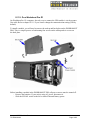
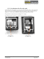
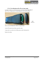
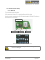
IV.1.4. On a Workabout Pro G2 via 4-way cable To install a module, you will need to remove the endcap on the WORKABOUT PRO. This is a simple process of unfastening four screws on the endcap USB Connector Make sure the WORKABOUT PRO is in suspend mode. On the GPS module take off the scanner flex cable. Connect the 4-way cable to the USB connector of the Workabout Pro. Replace the endcap. Integrated GPS Module – Datasheet TS-A00329-A02 Page 17/25 IV.2. Demo Software installation This part describes how to install and configure the GPS module on your device. To test this module we provide on the Psion Teklogix web site a demonstration tool called PT GPS. Other GPS applications can be configured with the same procedure, but for software development we advise you to refer to the “V. Developer guide” section. IV.2.1. GPS module installation With this document, we provide a setup package “GPSModuleSetup v1.2”. Follow this instruction to install it: 1. Copy the folder “GPSModuleSetup v1.2” onto your device. 2. Execute “Setup.exe”. 3. The installation process asks you first if the GPS is connected to the scanner port. If you use this connection the program installs a driver to switch on the scanner power. Else the USB expansion slot is enabled in the registry. 4. Then the second dialog box asks you if the GPS use the USB communication mode (USB is the factory configuration). If you answer “yes”, the USB driver is installed. 5. Click on “OK” to reboot the system. IV.2.2. Software installation The PT GPS application provided by Psion Teklogix is intended to show all the GPS features and facilitates the GPS board evaluation. You can download it on the Psion Teklogix Partner Database site and install the cab file corresponding to your operating system on your device. If you want to know more about this application, see the document PT GPS User Manual. Any other demo application for mobile devices can be used with this GPS. IV.2.3. Software configuration To configure your GPS software, you need to set the serial port settings as follow: The baud rate is always 9600bps For serial communication mode on the scanner port, the port number is COM3 For USB communication mode a serial port is emulated, and the port number COM5 is assigned automatically. If your configuration already uses the COM5 for another peripheral, you can modify the default GPS port number in the registry, please refer to the “V.3.2 GPS with USB communication mode” section for help. Once the right port is selected the background colour of PT GPS application becomes yellow or green. Integrated GPS Module – Datasheet TS-A00329-A02 Page 18/25 V. Developer’s guide This guide is about GPS power management, USB driver installation and communication settings. In this document we will not discuss how to manage the NMEA sentences. If you want more information about that, there is a lot of documentation and SDK on Internet. V.1. Power management According to your application, it could be useful to manage the GPS power to save battery life. To implement it, the WORKABOUT PRO HDK V2.01 available on the Psion Teklogix site is required. All the source code here is in C++ language, but a .Net wrapper for the HDK can be downloaded on the Psion Teklogix Partner Database. V.1.1. GPS on scanner flex cable Switch ON GPS: To enable GPS power on the scanner port, use the function ScannerPort:EnablePower(bool on) from the HDK API with the parameter “on” to true, and set the pin OutputBarWakeup to true. Switch OFF GPS To disable GPS power on the scanner port, use the function ScannerPort:EnablePower(bool on) with the parameter “on” to false, and set the pin OutputBarWakeup to false. Sample code: using namespace PsionTeklogix::WORKABOUTPRO_HDK::ScannerPort; using namespace PsionTeklogix::WORKABOUTPRO_HDK; void SwitchOnGPS() { // Switch on the 5V on the scanner port ScannerPort::EnablePower(true); // Set the BarWakeup pin (pin 18) to 1 Configure((ScannerPin) OutputBarWakeup, true); SetPinState(static_cast<ScannerPin>(OutputBarWakeup), true); Configure((ScannerPin) OutputBarWakeup, false); } void SwitchOffGPS() { // Switch off the 5V on the scanner port ScannerPort::EnablePower(false); // Set the BarWakeup pin (pin 18) to 0 Configure((ScannerPin) OutputBarWakeup, true); SetPinState(static_cast<ScannerPin>(OutputBarWakeup), false); Configure((ScannerPin) OutputBarWakeup, false); } Integrated GPS Module – Datasheet TS-A00329-A02 Page 19/25 V.1.2. GPS on expansion USB connector Switch ON GPS To enable GPS power on the expansion USB connector, use the function ExpansionUSB:EnablePower(bool on) from the HDK API with the parameter “on” to true. Switch OFF GPS To disable GPS power on the expansion USB connector, use the function ExpansionUSB:EnablePower(bool on) with the parameter “on” to false. Sample code: using namespace PsionTeklogix::WORKABOUTPRO_HDK::ScannerPort; using namespace PsionTeklogix::WORKABOUTPRO_HDK; void SwitchOnGPS() { // Switch on the 5V on the expansion USB connector ExpansionUSB::EnablePower(true); } void SwitchOffGPS() { // Switch off the 5V on the expansion USB connector ExpansionUSB::EnablePower(false); } V.1.3. WORKABOUT PRO USB hub Even if your GPS board is powered, you must check that the USB Hub into the Psion Teklogix hand-held computer is switch on. Use these functions to switch the USB Hub power: Switch ON USB hub To enable USB hub power, call the function USBHub:EnablePower(bool on) from the HDK API with the parameter “on” to true. Switch OFF USB hub To disable USB hub power on the expansion USB connector, call the function USBHub:EnablePower(bool on) with the parameter “on” to false. Sample code: using namespace PsionTeklogix::WORKABOUTPRO_HDK; void SwitchOnUSBHub() { USBHub::EnablePower(true); } void SwitchOffUSBHub () { USBHub::EnablePower(false); } Integrated GPS Module – Datasheet TS-A00329-A02 Page 20/25 V.2. USB driver installation On the GPS board a block of 6 switches configure the communication mode. If your GPS switches are set to USB, it is necessary to install the UBlox driver on the WORKABOUT PRO else, it will display a message box “Unidentified USB Device”. To install the driver you can launch “PsionTeklogix UBLOX_Setup.cab” available in the folder “cab” of the “GPSModuleSetup v1.2” package or create your own setup file. If you choose to do it yourself, you have to copy the driver UBXUSBSER.dll in the “\Windows” folder and add the following registry keys: HKLM\Drivers\USB\LoadClients\5446_420_256\Default\Default\UBXUSBSER\FriendlyName, with the value "Antaris(r)4 - GPS Receiver" HKLM\Drivers\USB\LoadClients\5446_420_256\Default\Default\UBXUSBSER\DeviceType, with the value 1 HKLM\Drivers\USB\LoadClients\5446_420_256\Default\Default\UBXUSBSER\Tsp, with the value "Unimodem.dll" HKLM\Drivers\USB\LoadClients\5446_420_256\Default\Default\UBXUSBSER\Prefix, with the value "COM" HKLM\Drivers\USB\LoadClients\5446_420_256\Default\Default\UBXUSBSER\Dll, with the value "UBXUSBSER.dll" V.3. Connection settings The GPS device is accessible through a serial port even if the USB communication mode is used (the UBlox USB driver emulates a serial port). The baud rate is allways 9600bps. V.3.1. GPS with serial communication mode The port number is COM3 for serial communication mode on the scanner port. V.3.2. GPS with USB communication mode For USB communication mode, the port number is automatically assigned to the COM5. But other port can be used by changing the registry key HKLM\Drivers\USB\LoadClients\5446_420_256\Default\Default\UBXUSBSER \Index with the value of the port number 1, 2, 4 or 5 (the COM3 is never available for USB device). Keep in mind that some port number are already used by the system and could not be assigned for the GPS. Integrated GPS Module – Datasheet TS-A00329-A02 Page 21/25 VI. Maintenance VI.1. Endcap assembly Here are all the required parts Fit the GPS board in the rubber boot Set up the switches to desired configuration (USB (default) or Serial) Fit the assembly in the multipurpose endcap (with the FFC and the 4-way connector connected) Screw the stopper in place Integrated GPS Module – Datasheet TS-A00329-A02 Page 22/25 This is a view of the assembled unit Integrated GPS Module – Datasheet TS-A00329-A02 Page 23/25 VI.2. Communication Setup VI.2.1. USB Link This is the default setup for the module. Follow instructions of chapter VI.1 to assemble and disassemble the endcap. In order to set up the communication of the GPS module through the USB link, DIP switches on the board must be set up as shown: Configuration switch 4 way conn. scanner connector GPS Module Electronic board Components side DIP Switches configuration for serial communication Never turn on switches 1 and 2 together. Permanent damage of the board would happen. Integrated GPS Module – Datasheet TS-A00329-A02 Page 24/25 VI.2.2. Serial Link This is the non-default setup for the module. Follow instructions of chapter VI.1 to assemble and disassemble the endcap. In order to set up the communication of the GPS module through the serial link, DIP switches on the board must me set up as shown: Configuration switch 4 way conn. scanner connector GPS Module Electronic board Components side DIP Switches configuration for serial communication Never turn on switches 1 and 2 together. Permanent damage of the board would happen. Integrated GPS Module – Datasheet TS-A00329-A02 Page 25/25