1
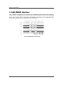
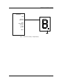
ZestETM1 User Interface Examples
4.2 Samsung S3C2416 Microcontroller
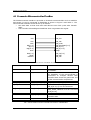
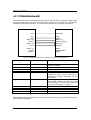
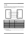
The Static Memory Controller (SMC) of this microcontroller can be connected to
ZestETM1 as shown in Figure 3 and Table 2. The SMC should be configured for:
• Synchronous single accesses.
• 2 wait states for writes and 1 wait state for reads. This places the data 2 clock
cycles after SMAVD, which is used as the CSn for ZestETM1.
ZestETM1
Samsung S3C2416
CLK
RSMCLK
CSn
WEn
BEn[1:0]
A[9:1]
DQ[15:0]
INTn
RSMAVD
nRWE
nRBE[1:0]
RADDR[8:0]
RDATA[15:0]
EINTn
EOF[1:0]
HEAD
LENGTH
nRCS[5:0]
nROE
nWAIT
RSMBWAIT
Figure 3. Samsung S3C2416 Connections to ZestETM1 User Interface in 16-Bit SRAM Mode
ZestETM1
Samsung S3C2416
CLK
RSMCLK
CSn
RSMAVD
WEn
BEn[1:0]
A[9:1]
nRWE
nRBE[1:0]
RADDR[8:0]
DQ[15:0]
INTn
RDATA[15:0]
EINTn
nRCS[5:0]
nROE
nWAIT
RSMBWAIT
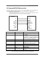
Comment
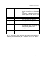
RSMCLK frequency should be from 5MHz
to 125MHz
Address Valid is used as the Chip Select
for ZestETM1. If the microcontroller is
connected to multiple devices then
Address Valid should be gated with one
of the microcontroller Chip Selects.
A is byte address and RADDR is word
address
so
A[0]
is
tied
low.
RADDR[25:9] are not connected.
Not connected, but see comment for
Address Valid
Not connected
Not used, tie high if not used for other
devices
Not connected
Table 2. Samsung S3C2416 Connections to ZestETM1 User Interface in 16-Bit SRAM Mode
CONFIDENTIAL
Page 7 of 18