1
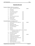
Chapter 1 - Getting Started
Page 1-1
1.1 INSTALLING ASAD FOR THE FIRST TIME
1.1.1
Installing the ASAD Program
Note: Read the installation instructions carefully. There are differences between Windows XP and
Windows 7
ASAD uses an automated installation program similar to most Windows software. To run the installation
program follow the following steps:
1. Insert the ASAD Installation CD into your CD-ROM drive.
2. Click on the ‘Start’ button and select ‘Run’.
3. Type path and file name of the ASAD install program:
(d:setup.exe, where d: is the CDROM drive), or you can select the file by clicking the ‘Browse’ button in the Run dialog box
and negotiating to the file location of the program disk. Once the path and filename are in the
‘Run’ dialog box, press ‘Ok’ to begin the installation.
4. (XP) The default installation subdirectory is ‘c:\Program Files\ASADv3’. The setup will prompt
you to enter the desired path for ASAD on your system’s hard drive. Using the default is
desirable.
(Win 7) The default installation subdirectory is ‘c:\Program Files\ASADv3’. CHANGE the
destination to ‘c:\ Program Files (x86)\ASADv3’
5. Once all the program files have been installed, continue to the next section…Installing the
Locking Mechanism.
1.1.2 Installing the Locking Mechanism
For ASAD to run, one of the following locking mechanisms must be satisfied:
• An ASAD Hardware Lock for the USB port. This key looks like a Green thumb-drive which had an
‘ASAD’ label on one side and the license number on the other.
• The Weekly Code (password) entered at ASAD startup.
Refer to Appendix D: Installing the Hardware Lock, page A-8 for a Network Lock or page A-14 for a
Standalone Lock.
Now that the ASAD software and the lock mechanism has been installed you can test to see it ASAD will
run by clicking on the ASAD icon on the desktop or run ‘c:\ Program Files\ASADv3\ASAD3.exe’ (in
Windows XP) or ‘c:\ Program Files (x86)\ASADv3\ASAD3.exe’ (in Windows 7).
1.1.3
Problems Installing on Windows 7
If your running Windows 7, ASAD may fail to start. If the error displayed indicates a missing DLL (most
likely MSVBVM50.DLL then follow the following steps.
1. Place the ASAD installation disk in the CD-Rom drive (d:)
2. Unzip file d:\Program Files\ASADv3\ASAD_DLL.ZIP into the ASAD subdirectory on your c: drive
(c:\Program Files (x86)\ASADv3\). This will place all DLLs required by ASAD into the ASAD
startup directory.
WARNING: DO NOT COPY the DLLs into \WINDOWS or \WINDOWS (x86) or
\WINDOWS\SYSTEM32…Etc.
Automated Storm Sewer Analysis and Design
Version 3.x.x
Chapter 1 - Getting Started
1.1.4
Page 1-2
Other Windows 7 Issues
The default installation and startup directory for ASAD if different in Windows 7 that in Window XP.
Windows XP
Windows 7
C:\Program Files\ASADv3\
C:\Program Files (x86)\ASADv3
If using Windows 7, then the secondary files locations for ASAD may need to be updated. See section 1.2.2
– ‘Setting File Locations’ to make the changes.
1.2 STARTING A NEW DRAINAGE PROJECT
1.2.1
Creating a New Drainage System Database
Note: Refer to appendix A “Step-by-Step User Flowchart” for an overall view of ASAD procedures
and sequence of events.
To create a new drainage system database in ASAD, use the mouse to click the ‘File’ pulldown menu, select
‘New Project’ from that menu. Type in the filename of the new drainage system database in the ‘New
Database Name’ field (see figure 1.1). A template file (SEEDv3.MDB) must also be selected. The template
file is a blank database file containing the specific fields necessary for ASAD to function.
Figure 1.1
New Database Name
Key in or browse the path and filename you want to create. The database may be created on any (local or
network) disk drive. This new filename MUST have the .MDB extension.
Seed File Name
Key in or browse the path to the ASAD v3 Seed Database file. The seed filename is typically SEEDv3.MDB
Browse (Button)
Use the browse button to search local or network disk drives for the new database location or the seed file.
Create (Button)
The create button will copy (and overwrite without a warning) from the seed file to the new file.
Automated Storm Sewer Analysis and Design
Version 3.x.x
Chapter 1 - Getting Started
Page 1-3
1.2.2 Setting File Locations
Most ASAD data is contained in the project database (*.mdb) file. However, there are some files which are
common to all projects and need to be separate from the project database. These files are Top files, Report
files, and Cell Libraries. The ‘File Locations’ window (see figure 1.2) allows the user to set the path to these
files. If these paths are not set correctly, then a ‘Missing Report File…’ or ‘Missing Top File…’ message
will be displayed when printing reports or drawing drainage structures, respectively. If the path to the cell
library is not set correctly for ‘Plan View’, then circles will be drawn in place of structures.
Windows 7 users should use path C:\Program Files (x86)\ASADv3\. Note the ‘(x86)’ is the difference
between Win 7 and XP setups. Standard XP setup is seen in Figure 1.2 (below).
Figure 1.2
Report Files – These files have an ‘.rpt’ extension and they control the format of ASAD reports such as the
Storm Tabs report. These files are, by default, installed into the ASAD subdirectory (usually C:\Program
Files\ASADv3\). Note: the ‘Report Files Path’ is simply the subdirectory which contains the ‘rpt’ files. It is
not set to a specific file.
Top Files - Top files, which have the extension ‘.top’, are used to draw the cross sectional view of drainage
structure tops. These are simple text files that contain the instructions for drawing vectors. Here’s an
example:
TAG 1
DRAW 0 -.6250
DRAW 3.25 -1.1667
TAG 2
DRAW 0.5 0
DRAW 0 0.5
DRAW_TAG 1
JUMP_TAG 2
etc...
These files are, by default, installed into the ASAD subdirectory (usually C:\Program Files\ASADv3\).
Note: the ‘Top Files Path’ is simply the subdirectory which contains the ‘top’ files. It is not set to a specific
file.
Automated Storm Sewer Analysis and Design
Version 3.x.x
Chapter 1 - Getting Started
Page 1-4
Cell Libraries - These files contain the cells drawn by ASAD. Cell library names usually have ‘.cel’
extension. The cell library commonly used to draw FDOT structures in plan view is DRPLAN.CEL. These
files are, by default, installed into the ASAD subdirectory (usually C:\Program Files\ASADv3\ or
C:\Program Files\ASADv3\Database). Note: Unlike the two previous settings, the ‘Cell Libraries’ setting is
set to the specific ‘cel’ file to be used.
Level Names Library – The file contains the levels and their ‘by level’ symbology for most levels used on
an FDOT project. See section 5.1.6 - Level Names & ASAD Master Level List.
Browse (button)
Use this button to locate the path or file.
1.2.3 Working in Concert with MicroStation and GEOPAK
ASAD CAD uses a graphics engine that is compatible with the MicroStation file format for files containing
the *.dgn naming convention. In addition to the compatibility with MicroStation, ASAD can interpret text
input files created by GEOPAK Coordinate Geometry to be used for defining horizontal and vertical
alignment. Refer to section 2.1.1 for Input file format and Importing Baselines and Profiles.
1.2.4 Project Setup Tips
It should be noted that some effort should be made during the project setup to identify drainage basins. This
will allow the designer to use naming conventions that give the drainage elements some meaning. Name the
drainage basins similar to the names given on the PD&E Study (if available) (e.g., Basin100, or Pond1).
(Valid basin names may have a maximum of eight characters with no spaces.) This in turn will promote the
user to name the nodes using the ‘S-‘ designation which will be important during plans preparation time
since the structure (node) names are used in the labels when drawing the drainage structures in plan view
and in cross section. This can also help simplify the job of the FDOT and permit agency reviewers if several
documents use the same naming convention as the plans. An example of the structure names is as follows:
‘S-121’, ‘S-350’. The basin name convention can also be incorporated in the pipe (reach) names. This is
merely a simple bookkeeping practice to associate the pipes with their respective basin and a relative
association with a group of structures. An example of the pipe names is as follows: ‘R-121’, ‘R-350’…
1.2.5 Migrating from V2 to V3
ASADv3 uses the same basic database structure as version 2 which makes the database backwards
compatible with version 2. When a version 2 database (*.mdb) is first opened by ASAD version 3, there will
be new fields inserted into the database. Most of these fields are specific to the Structure Definitions. Even
though the space for the new fields has been established in the database, the actual data has not been inserted
into these fields. For example; HDR_TEXT1, HDR_TEXT2, HDR_TEXT3, and HDR_TEXT4 (column
header text used in summary of drainage structures) are just a few of the new fields that are created in the
database. These fields, as well as others, have to be ‘filled in’ by the user. This can be accomplished by (1)
manually keying in the data, for each structure to be updated, using the pulldown: Edit>Structure Defintions
or (2) semi-automatically by copying the data from the version 3 seed database (seedv3.mdb) using the
pulldown: ‘File>Update Structures from Seed File’ (see figure 1.3).
Automated Storm Sewer Analysis and Design
Version 3.x.x
Chapter 1 - Getting Started
Page 1-5
Figure 1.3
Use the ‘Update Structures from Seed File’ window (see figure 1.4) by:
1. Select the seed file (typically SEEDV3.MDB) you wish to copy data from. Use the browse button to
search for the file.
2. Click on the ‘from’ structure in the list under the ‘Seed File:’ label.
3. Click on the ‘to’ structure in the list under the ‘Current File:’ label.
4. Click on the ‘Copy Selected Structures to the Review List’ button.
5. Return to step 2 and continue until all of the desired structures have been placed in the ‘Review
List’. Once finished, review the ‘Review List’ and delete any undesired entries.
6. Up to this point nothing has been changed in the database. To execute the copying commands in the
‘Review List’, simply click on ‘Apply’. To exit without making any changes, click on ‘Close’.
Figure 1.4
1.2.6 Rebuild Project Database to Maintain Database Integrity
The project database (*.mdb) is a MicroSoft Access database. Access databases have an unfortunate
tendency to bloat. They grow much larger than would appear to be necessary for the amount of data that they
Automated Storm Sewer Analysis and Design
Version 3.x.x
Chapter 1 - Getting Started
Page 1-6
are holding. This is due to a basic design feature of Microsoft Access and you need to do some regular
maintenance work to keep the situation under control.
The problem is that Access is not very good at reusing space in the mdb file and every change that you make
is saved in a new part of the database. This applies whether you are developing a database or just updating
the data; Access will extend the database to hold this new information rather than trying to use the existing
space again. Every change increases the size of the Access database and this bloat reduces its performance.
ASAD provides a method of compacting the database. Use pulldown File>Rebuild Project Database to
invoke Rebuild window (see figure 1.5). You may be surprised by the amount of space recovered; we have
seen a database grow to 5mb and reduce to 900kb after rebuilding.
A number of problems may stop you being able to run the rebuild procedure:
1. You or somebody else is using the database. Make sure you do not have the database open while
trying to rebuild it.
2. The database is read-only. Perhaps it is on a network drive where you do not have permission to
write or modify files. The most annoying reason is when Windows decides that the file on your hard
disk must be read-only because you have just copied it up from a CD. Right-click on the mdb file in
Windows Explorer, select Properties, then clear the Read only tick box.
3. The final problem is a rare one with modern hard disks. Access does need a lot of spare disk space
to be able to run the compaction. It needs to be sure of enough space for up to three copies of the
database; space for the source copy (renamed from your database name to REBUILD.BAK before
the process begins) and the new copy (named with the original database name) and also some
temporary working space whilst it's moving data from one to the other.
Figure 1.5
Automated Storm Sewer Analysis and Design
Version 3.x.x
Chapter 1 - Getting Started
Page 1-7
1.3 WORKING WITH THE ASAD CONTROLS
1.3.1 Main Program Window
The ASAD Main Program Window (see figure 1.6) is full of pulldown menus and function icons. This
section of the user’s manual is dedicated to describing the pulldown menus and function icons.
2
1
3
4
5
6
7
9
8
1
1
1
15
13
17
14
18
16
Figure 1.6
ASAD Main Program Windows Tool Names
1. ASAD Program Title Bar with Database path and name
2. Pulldown Menu Bar
3. Toolbar (docked at top)
4. Toolbar (free floating)
5. ASAD CAD Window
6. Vertical Pan Bar
7. Horizontal Pan Bar
8. Model Views
9. Smart Pick / Snap Toggle Switch
10. CAD Viewing Buttons
11. Reference Files On/Off Buttons
12. X & Y (east & north) Cursor Position
13. File load and process Progress Gauge
14. Position (station/offset) of Cursor in CAD Drawing
15. Current Active Storm Sewer System
16. Current Baseline for Cursor Position (see #14)
17. Drawing List & Undo Button
Automated Storm Sewer Analysis and Design
Version 3.x.x
Chapter 1 - Getting Started
Page 1-8
18. ASAD Message Area
1.3.2 Pulldown Menu Summary
File
All file manipulation controls for opening databases and CAD files are contained in this pulldown.
Project Global settings for the project units, metric or English.
Edit
All design input features are opened from this pulldown.
CAD
All CAD file and element manipulations are controlled from this pulldown.
Compute / Reports All hydraulic computations and various reports are started from this pulldown.
Tools
Floating toolbars, metric/English units converter.
1.3.3 Floating Toolbars
To invoke any of the 9 floating tool bars, from the Pulldown menu, select Tools>Tool Bars. ASAD’s
Floating Toolbars can be docked to any sidewall (top, bottom, left or right) or free floating depending upon
where you drag and drop them. When free floating, the toolbars can be resized by grabbing a side of the
toolbar and stretching or compressing it.
1.3.4
Floating Toolbar Icons and Functions Summary
Storm Sewer:
System Add / Delete - Adds or Deletes a Drainage System - See Section 3.1.1
Outfall Details - Set the outfall node, storm events and runoff coefficients, and QA/QC details See Section 3.1.2
System Divide - Group nodes and reaches to divide into new storm sewer system - See Section
3.1.3
Renumber System - Renumber nodes and reaches to reflect user defined throughout the entire
current system position - See Section 3.5
Nodes Edit - Define all node characteristics - See Section 3.3
Reach Edit - Define all reach characteristics - See Section 3.4
Structure Definitions - Set the structure dimensions and type - See Section 3.6
Pipe Definitions - Set the pipe type with flow characteristics - See Section 3.7
Roadway Geometry:
Baselines - Define horizontal characteristics - See Section 2.1
Profiles - Define vertical characteristics - See Section 2.2
Cross Slopes - Set typical section cross slopes - See Section 2.3
Cross Widths - Set typical section cross widths - See Section 2.4
Compute:
Compute Lengths, Elevations and Areas - Step 1 Hydraulics computation dialog - See Section
4.1
Automated Storm Sewer Analysis and Design
Version 3.x.x
Chapter 1 - Getting Started
Page 1-9
Compute Pipe Sizes - Step 2 Hydraulics computation dialog - See Section 4.2
Set Flow Lines - Step 3 Hydraulics computation dialog - See Section 4.3
Compute / Print Storm Tabs - Step 4 Hydraulics computation dialog - See Section 4.4
Cost Analysis - Determines system cost based on unit cost - See Section 4.6
PGL Elevation Inquiry - Displays PGL as a specific location - See Section 4.7
Drawing:
Draw Plan View - Nodal diagram in CAD - See Section 5.2.1
Draw Profile View - Scaled vertical alignment in CAD - See Section 5.2.2
Draw Drainage Structures (XS) - Plots drainage structures in CAD - See Section 5.2.3
Draw Baseline Locations - Plots segments of Baseline in CAD
View:
Refresh CAD Screen - Redraws elements in CAD window
Window Area - Magnifies user specified area in CAD display
Zoom In - Magnifies display CAD display window
Zoom Out - Increases display area in CAD window
Windows Center - Magnifies CAD display centered about user defined area
Fit Current System - Displays extents of selected drainage system
Fit All - Displays all elements in CAD file - See Section
Drawing/Reference Files:
Reference Files - Reference file control dialog - See Section 5.1.2
All Refs On - Displays all reference files in CAD - See Section 5.1.4
All Refs Off - Hides all reference files in CAD - See Section 5.1.4
Compress Design File - Decreases CAD file size - See Section 5.1.1
File Design - Saves updates to current CAD file - See Section 5.1.1
Fence:
Place Fence - Selects element group within user defined area
Fence Copy - Duplicates elements within a user defined area
Fence Move - Translates elements within a user defined area
Fence Delete - Removes elements within a user defined area
Fence Lock - Inside - Filters elements contained within fence
Fence Lock - Overlap - Filters elements contained through fence
Settings:
Automated Storm Sewer Analysis and Design
Version 3.x.x
Chapter 1 - Getting Started
Page 1-10
Levels Display - Element level display control
Levels Used - Lists all element levels used in CAD
View Attributes - Displays element properties in a CAD file
Elements:
Copy Element - Duplicates user selected element
Move Element - Translates user selected element
Delete Element - Removes user selected element
Modify Line - Translates single linear element endpoint
Measure Between Points - Calculates distance between two user specified points
Measure Area By Points - Calculates area contained within three or more user defined points
Place Line - Draws linear element
Place Line String - Draws multi-segmented linear element
Place Block - Draws rectangular shaped element
Place Shape - Draws multi-segmented closed shape element
Place Arc - Draws circular arc at user specified point of user defined radius
Place Ellipse - Draws ellipse at user specified point of user defined radii
Automated Storm Sewer Analysis and Design
Version 3.x.x