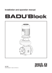
1
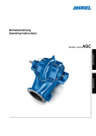
Installation and operation manual
Norm Block Pump
08/09
VG 766.1320.050 2' 08/09
1.
General information
GB
CAUTION
Speck Pumpen Verkaufsgesellschaft GmbH,
Neunkirchen am Sand
Series norm block pumps
Country of origin: Federal Republic of Germany
2.1 Symbols for safety instructions used in the operation manual
Safety instructions for the prevention of danger to persons are indicated by the safety symbol denoting
a general hazard area according to ISO 7000 –
04324:
This Speck pump has been developed and constructed with greatest care corresponding to state-ofthe-art technology and is subject to permanent quality
checks.
This operation manual introduces the user to the
pump and its intended uses.
Please pay attention to the instructions for operating
the pump safely, appropriately and efficiently in order
to ensure its reliability and longevity, as well as to
avoid danger.
The operation manual makes no mention of local regulations! The user alone is responsible for making
sure these are adhered to – also by assembly personnel.
When operating this unit, do not exceed the values – as put down in the technical documentation – with regard to the pumped fluid, flow rate, motor
speed, density, pressure and temperature as well as
motor performance or other specifications in the operation manual or the contractual documentation.
When in doubt, please contact manufacturer.
The nameplate identifies the series / size, the most
important operating data and the identification number. Please always quote this number on any inquiries, reorders and especially spare part orders.
Should you require any additional information or advice, or should any damage occur, please contact the
closest Speck customer care service.
To caution against electrical hazards, the safety symbol according to IC 417 – 5036 is used:
Safety instructions for the prevention of danger to
the machine and its functions are emphasized by
the word
ACHTUNG
Symbols which are affixed directly to the machine, as
e.g.
- an arrow denoting the direction of rotation
- sign for fluid connections
must by all means be paid attention to and kept fully
legible.
2.2 Qualification and training of staff
1.1 Certificates of conformity, test symbols and related matters
Staff responsible for operating, service, inspection
and installation must be fully qualified for these tasks.
The CE-symbol is attached to the pump. The certificate of conformity is part of the appendix of this operation manual.
The details of staff responsibility, competence and
surveillance are to be regulated by the user. If the staff
lacks the required skills, they must be trained and instructed. The user may charge the manufacturer with
doing so. Furthermore the manufacturer must make
sure that the staff fully understands the contents of
the operation manual.
1.2 Noise level
The noise level mostly depends on the lines connected to the pump.
The noise level stated is only valid for the pump on its
own.
The noise level data are included in the Technical
Data Sheet in the appendix. If the noise level is not
specified, it is lower than 75 dBA.
2.
Ignoring safety instructions can be dangerous as well
to persons as to the environment and the machine.
Ignoring the safety instructions will void any warranties.
Safety
In detail, ignoring the safety instructions may cause:
This operation manual contains fundamental instructions concerning installation, operation and servicing.
Therefore, the mechanic, the staff in charge of the machine as well as the user must study this operation
manual before installation and start-up. Keep the operation manual permanently available at the installation
site.
- failure of important functions of the machine / unit
Not only all general safety instructions in this chapter
must be observed, but also the special safety instructions in the other chapters.
2
2.3 Dangers of ignoring safety instructions
- failure of prescribed methods of servicing and maintenance
- danger to persons caused by electrical, mechanical
and chemical impact
- danger to the environment caused by leakage of
hazardous substances
- damage to institutions and buildings
2.4 Safety-conscious operating
The safety-instructions specified in the operation manual, national directions for accident prevention as
well as the user’s internal directives for operational
safety must be observed.
2.5 Safety instructions for the user / operator
transport straps. Do not hang the pump by its free
shaft extension or the ring terminal of the motor! The
ring bolts on the motor are only to be used for transporting the motor, not the whole pump!
A pump slipping through a transport strap can
injure persons and damage objects!
- Dangerously hot or cold machine parts must be protected from accidental contact by the user.
- Do not remove equipment which protects the machine against accidental contact from moving parts
(e.g. a clutch), when the machine is in operation.
- Leakages (e.g. at the shaft seal) of dangerous pumping materials (e.g. explosive, toxic, hot) must be
discharged without causing danger to persons or
the environment. Observe legal requirements!
- Eliminate any possibility of danger caused by electrical power! For details see e.g. regulations of VDE
and the local utilities.
2.6 Safety instructions for maintenance, inspection
and installation
The user must make sure that authorized and qualified expert staff only is put in charge of maintenance,
inspection and installation. These experts must have
thoroughly studied the operation manual before beginning their work.
The pump must be at ambient temperature, depressurized and empty.
On principle, the pump must stand still to be worked
on. By all means follow the shutting down process as
described in the operation manual.
Pumps or pump units conveying materials which are
dangerous to health must necessarily be decontaminated.
Immediately after work on the machine is finished, all
safety and protection equipment must be reinstalled
on the machine and reactivated.
VD 60.017
If the pump is transported without the motor, shaft 210
must be fastened:
1. Press the cover panels 68-3 lightly together and remove them through the windows of the lantern bracket 341.
2. Pull the lock washer 931 into the well nut and secure it by means of hexagon head screws 901.3.
Before restarting the machine, observe all instructions
in chapter “Initial start-up” in the operation manual.
2.7 Unauthorized modification or production of spare
parts
Changing or modifying the machine is only permitted
after consulting the manufacturer. The safety of the
machine can only be guaranteed if original spare parts
and accessories which are authorized by the manufacturer are used. The manufacturer does not assume
responsibility for the consequences which result from
the use of components from other suppliers.
2.8 Unauthorized operation
The operational safety of the delivered pump can only
be guaranteed, if the pump is appropriately used according to the specifications in the subsequent chapters of the operation manual. The limits stated in the
data sheet must not be exceeded under any circumstances.
3.
Transport, temporary storage
3.1 Transportation
The unit must be transported appropriately. During
transportation, the pump must be firmly fixed in a horizontal position to keep it from slipping through the
VD 60.016
3
3.2 Temporary storage
(Internal storage) rust-proofing
In case of temporary storage only the low-alloyed
components in contact with liquids (e.g. cast iron JL
1040) need to be rust-proofed. Commercially available preserving substances can be used for this. For
application / removal follow the specific instructions of
the manufacturer.
The procedure is described in Section 6.3.
The unit / pump ought to be stored in a dry room, preferable with constant humidity.
For outside storage it is necessary for unit and
packing case to be protected by a watertight cover in
order to avoid contact with moisture.
CAUTION
Protect stored goods against moisture, dirt, vermin
and unauthorized access! All openings of the assembled components of the unit are closed and must only
be opened if required during assembly.
For rust-proofing all blank parts and surfaces are
oiled, respectively greased (silicon-free oil and
grease).
4. Description of product and accessories
4.1 General description
Norm block centrifugal pumps are non self-priming,
mono-stage, spiral casing pumps in horizontal block
design.
They achieve a high circulation, while taking little
space because of their compact design.
The back-pullout design allows the drive unit to be replaced without disconnecting the pipe-work for ease
of assembly or disassembly.
4.2 Constructional design
Construction:
Spiral pumps, mono-stage with power rating according to EN 733. Shaft equipped with a replaceable
shaft sleeve in the area of the shaft seal. Spiral casing and impeller equipped with replaceable split
rings.
Flanged pump and motor are close-coupled to form a
block unit with norm motor.
The pump shaft is rigidly connected with the motor
shaft.
Shaft seal:
Mechanical seal according to EN 12 756.
Drive:
Electrical motor.
Protection against accidental contact:
Cover plates on the lantern brackets in accordance
with EN 294.
4.3
Table of materials:
Version
05
11
12
Casing parts
Tin bronze
CC480K-GS
Cast iron
EN-JL 1040
Cast iron
EN-JL 1040
Impeller
Tin bronze
CC480K-GS
Cast iron
EN-JL 1040
Tin bronze
CC-480K-GS
Mechanical seal
Carbon/SiC/EPDM
On request
SiC/SiC/HNBR
Carbon/SiC/EPDM
On request
SiC/SiC/HNBR
Carbon/SiC/EPDM
On request
SiC/SiC/HNBR
Split rings
CC495-GS
CC495-GS
CC495-GS
Pump shaft
1.4571
X6 Cr Ni Mo Ti 17-12-2
1.4571
X6 Cr Ni Mo Ti 17-12-2
1.4571
X6 Cr Ni Mo Ti 17-12-2
Shaft protection
sleeve
1.4571
X6 Cr Ni Mo Ti 17-12-2
1.4571
X6 Cr Ni Mo Ti 17-12-2
1.4571
X6 Cr Ni Mo Ti 17-12-2
Drive lantern
Cast iron
EN-JL 1040
Cast iron
EN-JL 1040
Cast iron
EN-JL 1040
VD 60.002
5.
5.1
Installation
Checks before installation
The structural layout must be prepared in accordance with the dimension and assembly drawings.
The concrete foundations should be of sufficient
strength (min. class X0) according to DIN 1045.
The concrete foundation must have set before the
unit is set up on it. The surface of the foundation
must be horizontal and even.
5.1.1 Ground, foundations, wall
It must be possible to set up the pump, respectively
the unit safely and stress-free on the foundations.
Distortions can cause an untimely wearing of the
pump.
Make sure that no vibrations are passed on through
the foundations.
5.1.2 Space requirements for operation and maintenance
When installing the unit, make sure that it is possible
to exchange parts of or the complete unit. Heavy
units must be equipped with appropriate facilities for
fastening and supporting lifting tools and other devices. Access routes for delivery and removal must be
provided.
5.2 Installation of the unit
During installation the unit must be leveled with the
help of the water level on the pressure connection.
Spiral casing and pressure cover will approximately assume the temperature of the pumped liquid. Pressure cover and lantern bracket must
not be insulated.
Appropriate measures have to be taken to avoid
burns.
5.3 Connecting the pipes
CAUTION
The pump must not be used as an anchor point for
pipes under any circumstances.
The pipe system must not exert any forces and momentums on the pump (e.g. by distortion or heat expansion).
4
When laying the suction line, make sure it ascends
towards the pump. The supply line must descend towards the pump. The pipes must be supported directly in front of the pump and have stress-free connections.
adequate distance from the drill holes for the measurement.
The set-up for the flow rate measurement must follow the regulations of the manufacturer of the measuring instrument.
The nominal diameter of short pipes must at least
equal the diameter of the pump connections. The
most economical diameter of long pipes must be determined individually.
Adaptor pieces for larger nominal diameters should
be designed with an enlargement angle of approx.
8° in order to avoid increased pressure loss.
The advisability of non-return valves and shut-off
valves depends on the type of unit and of the pump.
Suitable measures must be taken to compensate for
the thermal expansion of the pipes in order not to
strain the pump beyond the pipe forces and momentums permitted.
Exceeding the pipe forces may cause the appearance of leaky spots where the pumping
material oozes out.
Hot pumping materials may cause danger of life!
The flange covers on the suction and pressure connection must be removed before installing the piping.
Before starting the unit, the tanks, pipes and connections must be thoroughly cleaned, rinsed and air
purged. Weld beads, scaling and other impurities
often only dissolve after a long time.
5.3.1 Supplementary connections
See installation drawing or pipe layout diagram for
dimensions and position of the supplementary connection for the pump.
5.3.2 Dimensioning of the pipes
In order to avoid friction loss, the flow rate must be
max. 1.5m/s in suction or supply lines, max. 2.5 m/s
in pressure lines.
The rules of piping construction must be observed
concerning the piping layouts and the liquid quantities in order to prevent the pump from sucking air.
Dry running of the pump can cause considerable damage to pump and seals.
5.3.3 Measuring point diagram
The pressure of centrifugal pumps is measured following ISO 2548 “standardized experimental arrangements” (sketch 1, page 48).
Make sure, however, that the flow rate in the measuring pipe does not considerably exceed the values
stated in 5.3.2. If the flow rate exceeds those values,
the pressure / suction flanges must be equipped with
adaptor pieces. (sketch 2, page 48)
To ensure a reliable measurement, follow the instructions in chapter 5.3.2 and the corresponding
sketch with regard to the flow rate values when measuring pressure.
Pipe elbows, valves, adaptor pieces etc. can falsify
the measuring results and must therefore be at an
5
Sketch 1
Sketch 2
VD 60.018
5.4
Electrical connection
The electrical connection may only be carried out by
a qualified electrician.
Observe DIN VDE regulations 0100 and explosive
atmosphere regulations 0165.
Compare the voltage at hand with the data on the
motor rating plate and select the appropriate connection.
Observe the technical connection provisions of
the local utility when connecting the unit.
The use of a motor protection device is strongly recommended.
5.4.1 Motor connection
The direction of rotation of the three-phase AC motor
is strictly clockwise in accordance with DIN VDE
0530 part 8 (looking on the motor stub shaft).
The direction of rotation of the pump is anti-clockwise (looking on the suction flange).
To convert the motor to the direction of rotation of
the pump, it should be connected following fig. 5.41 or fig. 5.4-2.
6
connection Δ (low voltage)
Fig. 5.4-1Connection diagram for three-phase
AC motors, connection Δ
Connection Y (high voltage)
- the direction of rotation has been checked
- all supplementary connections have been made.
6.1.1 Shaft seal
Shaft seal (see 7.4.4 and 7.5.2)
6.1.2 Filling and checking the pump
The pump and its supply line must be vented and filled with pumping fluid before start-up.
The shutoff valve in the suction line must be completely open.
CAUTION
VD 25.226
Fig. 5.4-2 Connection diagram for three-phase
AC motors, connection Y
If required, connect PTC thermistor according to DIN
44081 / 44082 to downstream triggering unit following fig. 5.4-3.
Running he pump dry will cause increased wear
and must be avoided!
6.1.3 Final check
It must be possible to turn the shaft by hand with
ease. Check if the connections are working properly.
6.1.4 Protection against accidental contact
According to accident prevention regulations the pump may only be operated if it is protected against accidental contact.
6.1.5 Switching on
Only switch the unit on with the shutoff valve on the
pressure side switched on! When full speed is reached, open it slowly and adjust it to the operating
point.
CAUTION
Fig. 5.4-3 Connection diagram for PTC thermistor
5.4.2 Timer relay setting
Make sure for three-phase AC motors with star-delta
circuit that there is a speedy switchover between star
and delta. Long intervals will cause damage to the
pump.
For star-delta circuits set the timer relay to <3 s.
5.4.3 Checking the direction of rotation
The motor’s direction of rotation must correspond to
the direction of the arrow on the spiral casing (as viewed from the motor side in clockwise direction).
Check by switching the motor on and then immediately off again.
The direction of rotation must only be checked with
the pump and the pipes primed, as important components can be destroyed if the pump runs dry.
In case of wrong direction of rotation, reverse any
two phases L1, L2 or L3 of the supply line in the terminal box of the motor.
6.
6.1
Start-up / switching off
Initial start-up
CAUTION
Before starting the pump ensure that:
- the unit is electrically connected and all prescribed
protective measures are taken.
- the pump is filled with pumping material
After reaching operating temperature and / or in
case of leakages, tighten the hexagonal nut 920.2
or .3 or .4 after switching the unit off.
6.1.6 Switching off
Close the shutoff valve in the pressure line.
If a non-return valve is installed in the pressure line,
the shut-off valve can remain open as long as there
is back pressure.
When switching the pump off, the shutoff valve
in the supply line must not be closed.
Switch off the motor. Make sure that it coasts quietly
to a halt.
Depending on the unit the pump - after the heating
source has been switched off – should coast for long
enough to reduce the temperature of the pumped
fluid enough to prevent the heat from accumulating
inside the pump.
For a long standstill close the shutoff valve in the
supply line. Close the supplementary connections.
In order to protect the pump against frost and in case
of a long standstill, the pump should be emptied.
6.2 Operating range limits
6.2.1 Temperature of the pumped fluid
CAUTION
Do not operate the pump at temperatures higher
than those specified on the data sheet or on the rating plate.
6.2.2 Switching frequency
In order to avoid a notable increase of the temperature inside the motor and an excessive strain on the
pump, motor, seals and bearings, the following num-
7
ber of switching cycles per hour (h) must not be exceeded.
Norm block pumps 15 switching cycles per hour
6.2.3 Minimum volume
If the type of unit includes the possibility of operating
against a closed shutoff valve on the discharge side,
provide a minimum pumping volume at
t –30 bis + 70 °C ≈ 15 % von Qopt.
t >30 bis + 140 °C ≈ 25 % von Qopt.
6.2.4 Density of the pumped fluid
The power consumption of the pump changes in proportion to the density of the pumped fluid. In order to
avoid overloading of motor and pump, the density
must be consistent with the order data.
6.3 Switching off / storage / rust-proofing
Every pump is carefully assembled before it leaves
the factory. If start-up is to be delayed for any length
of time after delivery, we recommend to store the
pump as described below.
6.3.1 Storing new pumps
- New pumps are packed ready for storing in the
factory.
Protection lasts for approx. 12 months, when appropriately stored inside.
- Store the pump in a dry place.
6.3.2 Procedures for an extended non-operational
period
1. The pump remains installed and has its functions checked periodically
In order to ensure a constant operational readiness and to prevent deposits on the inside of the
pump, a test run of the pump must be carried out
(for approx. 5 min.) every 1 -3 months during a
long standstill. Only run the pump, if it is filled with
an adequate amount of water.
2. Pump is dismantled and stored
Before storing the pump it must be checked according to chapters 7.1 and 7.4. Then proceed
with rust-proofing:
- Spray the inside of the pump with preservative
agent, especially the area around the impeller
gap. Spray the preservative agent through the
pressure and suction connection. It is advisable
to close the connections (e.g. by means of plastic caps or similar).
6.4 Restart after storage
Before restarting the pump, the checks and maintenance works must be carried out according to 7.1
and 7.2.
For restarting the pump, also observe the instructions in chapter “Initial start-up” (6.1) and
“Operational range limits” (6.2).
Immediately after finishing these activities, all
safety and protection equipment must be reinstalled and reactivated.
7.
7.1
8
Maintenance / Inspection
General instructions
The user has to make sure that maintenance, inspection and installation is carried out by authorized
and qualified expert staff after thoroughly studying
the operation manual.
Drawing up a maintenance schedule will help avoid
expensive repairs at minimal maintenance costs and
ensure failure-free and reliable operation of the
pump.
Principally the machine must only be worked on when disconnected from electricity.
The pump unit must be protected against accidental switch-on in order to avoid danger of life.
Pumps which convey fluids which are dangerous to health must be decontaminated.
When draining the fluid make sure to avoid any
danger for persons and the environment. Observe legal requirements to avoid danger of life!
7.2 Maintenance / Inspection
7.2.1 Monitoring
CAUTION
The pump ought to run smoothly and vibration-free
at all times.
The pump must not run dry!
Do not run the pump against a closed shut-off
valve in order to avoid heating up of the pumped fluid.
Max. permissible ambient temperature 40°C.
Storage temperature may exceed room temperature
by 50°C, but by no means rise beyond 90°C (measured on the outside of the motor casing).
For the required minimum volume see 6.2.3.
Make sure the shut-off valve in the supply line
is not closed when the pump is in operation.
A properly working mechanical seal must have no,
or only a small amount of visible leakage losses (vaporous). It is maintenance-free.
Installed reserve pumps must be operated at least
once a week by fast on and off-switching to ensure
constant operational readiness.
Watch the functioning of the supplementary connections.
7.2.2 Lubrication and lubricants
7.2.2.1 Lubrication
The roller bearings in the IEC motor are lubricated
with grease. Intervals, quality and amount are specified subsequently.
7.2.2.2 Quality of grease / grease change
The bearings are filled with high-quality, lithium-soap
grease. Under normal operating conditions the filling
will last for 15,000 operating hours or for 2 years.
Under bad operating conditions, e.g. high ambient
temperature, high humidity, dusty air, aggressive industrial atmosphere etc., the bearings should be
checked earlier and, if necessary, be cleaned.
For this purpose use grease containing lithium soap.
It should be free of resin and acid, must not become
brittle and should provide rust protection. The grease
should have a penetration value between 2 and 3,
corresponding to a walk penetration of 220 to 295
mm/10. The drop point ought not to be below 175°C.
The cavities in the bearings may only be approx. half
filled with grease.
If necessary, the bearings can be filled with greases
containing other soap bases. As greases containing
different soap bases may not be mixed, the cavities
must first be cleaned. The lubrication intervals may
have to be adjusted to the requirements of these
greases.
CAUTION
General legal requirements regarding disposal have
to be observed.
Sealed bearings with permanent lubrication (2 RSbearing or 2 Z bearing) cannot be washed out and
refilled with grease. Therefore the bearings must be
exchanged.
Motors from manufactured size 180 are equipped
with re-lubrication devices and flange lubrication
nipples in accordance with DIN 3404.
7.3 Emptying / disposal
If the pump was used for conveying fluids dangerous to health, make sure not to endanger
persons or the environment when emptying the
pump. Observe legal requirements! If necessary,
wear protective clothing and a protective mask!
7.4 Demontage
Before starting the disassembly, make sure
that the pump cannot accidentally be switched
on. The shut-off valves in the pressure / suction line
must be closed.
The pump must be at ambient temperature, depressurized and empty.
Disassembly and assembly may only be carried out
as described on the exploded drawing.
7.4.1 Basic instructions
Repairs and maintenance of the pump must only
be put to the charge of specially trained staff using
original spare parts (see 2.7).
Observe safety precautions according to instructions in chapter 7.1. When working on the
motor, observe the instructions and regulations
of the manufacturer. Disassembly and assembly
must be carried out following the sequence on
the explosion drawings on pages 56 to 63.
In case of damage, please contact the customer service facility closest to you.
See the attached list of addresses for our customer
service locations.
7.4.2 Preparations for disassembly
1 Cut off electricity.
2 Disassembly of the complete unit
2.1 Disconnect the motor leads
2.2 Disconnect the pressure / suction connections
from the pipes
2.3 Depending on the manufactured size of the
pump / motor, unfasten the mounting bolts of
the motor base from the foundation.
2.4 Pull the complete unit out of the piping.
3 During disassembly the pump casing remains in the piping.
3.1 Disconnect motor.
3.2 Unscrew hexagonal nut 920.2 / .3 / .4.
3.3 Depending on the manufactured size of the
pump / motor, unfasten the mounting bolts of
the motor base from the foundation.
3.4 Pull the complete installation set and the motor
out of the pump casing.
4. Pump remains in the piping; disassembly of
the motor:
4.1 Disconnect the motor.
4.2 Press the cover panels 68-3 slightly together
and remove them through the windows of the
lantern bracket 341.
4.3 Unscrew the hexagonal nut 920.5..
4.4 Unscrew the hexagonal nut 901.3.
4.5 Place both locking plates 931 on the shaft key
seat 210.
4.6 Tighten hexagonal bolts 901.3.
4.7 Detach the motor.
After a long period of operation individual parts may
possibly be hard to detach from the shaft. In this
case use one of the well-known rust solvents or, if
possible, a suitable extractor tool.
Do not use force under any circumstances!
7.4.3 Pump
Disassembly of the pump must be carried out as
described on the explosion drawing on pages 56
to 63.
7.4.4 Mechanical seal
In order to exchange the mechanical seal, it is necessary to disassemble the pump.
After removing the impeller 230 pull the mechanical
seal 433 from the shaft by hand.
Before assembly clean the shaft sleeve and remove
any scores and scratches with emery cloth, if necessary. If scoring or pitting is still visible, replace
the shaft sleeve, clean the counter-ring seat.
7.5 Reassembly
7.5.1 Pump
When assembling the pump, observe the machinebuilding regulations in force.
Before assembly brush the mating areas of the individual parts with graphite or a similar substance.
This applies equally to bolt connections.
Check O-rings for damage and replace where necessary.
As a general rule, gaskets must be replaced. Always
replace them with seals of the same thickness.
Gaskets made from asbestos-free materials or graphite must be assembled without the use of lubricants on principle.
Assembly aids should be avoided if at all possible.
However, if necessary, use a commercially available contact adhesive (e.g. Pattex) or HY-LOMAR or
Epple 33 sealant. Apply a thin film of the sealant at
selected points. Cyanoacrylate adhesive (instant
glue) must not be used.
If the sealing area between the impeller neck and
the split ring is worn, the split ring 502.1 and, if existing, 502.2 must be renewed.
Play in the gap:
new 0.3 mm in Ø
max. permissible extension to 0.9 mm in Ø
9
The assembly is carried out following the sequence
of disassembly in reversed order. The correct sequence of the individual parts must be maintained.
7.5.2 Mechanical seal
Installation is carried out following the sequence of
removal in reversed order. The basic rules for assembling a mechanical seal are as follows:
Maximum care, extreme cleanliness.
Only remove the contact protection from the slide
faces immediately before starting the assembly.
Avoid damaging the sealing surfaces and the
O-rings.
Clean the shaft and the counter-ring seat in the pressure cover and carefully remove deposits.
During installation of the seal, the friction forces of
the shaft sleeve 523 can be reduced by wetting its
surface with water.
CAUTION
Elastomers made of EP-rubber must never come
into contact with oil or grease.
Use water as fit-up aid.
Always press in the counter-ring into the pressurecover 163 by hand or finger. Apply pressure evenly.
7.5.3 Assembly of the motor
When mounting the motor, follow the reversed sequence of dismantling it. During installation and before start-up, make sure to pull the locking plates
931 out of the shaft keyseat and secure them with
the hexagonal bolts 901.3.
CAUTION
When mounting the shaft 210 onto the motor stub
shaft, ensure that the keyseat on the motor shaft end
and the slot of shaft 210 are congruent and positioned opposite to the slot of clamping ring 515.
10
7.5.4 Screw tightening torques
VW 60.007
Schnitt A-A
Fig. 7.5-2 Bolt tightening points for pump unit
Item
A
B
C
D
VW 60.006
Fig. 7.5-1 Shaft assembly
Part No.
Part name
210
515
901.3
914.1
931
Shaft
Clamping ring
Hexgonal bolt
Allen screw
Locking plate
1)
Thread size
[mm]
M 10
M 12
M 12 x 1,5
M 20 x 1,5
M 30 x 1,5
M8
M 10
M 12
M 16
M6
M8
Tightening torque 1)
MA [Nm]
40
55
25
85
140
15
30
45
80
10
25
Refers to non-lubricated threads
A= Bolt connections on the casing parts
B= Impeller nut
C= Bolt connections lantern bracket / motor
D= Bolt clamp ring / stub shaft
11
7.6
Ordering spare parts
Any order of spare parts must include the following
information as specified on the rating plate, e.g.:
Type
norm block pumps 50/160
Serial number:
Model:
Year of manufacture: 2002
or the spiral house casing, e.g.: 50/160
7.6.1 Recommended stockkeeping of spare parts for two years of continuous operation according to DIN 24 296
Part No.
Part name
Quantity of pumps (including reserve pumps)
2
3
4
5
6 and 7 8 and 9
10 and more
Quantity of spare parts
210
Shaft
1
1
1
2
2
2
20 %
230
Impeller (including split ring 502.2)
1
1
1
2
2
2
20 %
230.1/.2
Impeller (set)
1
1
1
2
2
2
20 %
400.1/.2
Gaskets (set)
4
6
8
8
9
12
150 %
412.3
O-ring
2
3
4
4
4
5
100 %
433
Mechanical seal
1
1
2
2
2
3
25 %
502.1
Split ring
2
2
2
3
3
4
50 %
523
Shaft sleeve
2
2
2
3
3
4
50 %
12
Faults / causes and remedies
Flow rate of the pump too low
Driving engine overloaded
Protective motor switch de-energized
Increased storing temperature
Pump is leaking
Shaft seal is leaking excessively
Pump is running erratically
Unacceptable temperature increase in the pump
8.
l
Cause
Pump operates against too much pressure
Back pressure too high
Pump or piping not completely
deaerated or not completely filled
Supply line or impeller blocked
l
Formation of air pocket in piping
l
l
l l
l
l l
l
l
l
l
l l
l
l
l
l
Wrong direction of rotation
Wear on internal parts
Pump’s back pressure is lower than
stated in the purchase order
Higher density or higher viscosity of the pumped
fluid than stated in the purchase order
Defective seal
l
l
Shaft seal worn
Scores or roughness on the shaft sleeve
l
Pump runs erratically
l l
Pump is twisted
l
Increased axial stroke 2)
l
Too little, too much or unsuitable lubricant
Running on 2 phases
l l
l
Suction height too large/NPSHunit (supply too low)
l
Rotor out of balance
l
l l
Bearing damaged
Flow rate too low
Protective motor switch incorrectly adjusted
Transport safety devices have not been
removed from the keyseat
1)
2)
Remedy 1)
Set new operating point
Check the unit for impurities
Deaerate or top up
Remove deposits in the pump or the piping
Change piping
Insert an air-bleed valve
Correct liquid level
Open shut-off valve in the supply line
If the resistance in the supply line is too heavy,
change supply line.
Check the installed filters/suction openings
Reverse two phases of the power supply
Exchange worn parts
Adjust operating point
2)
Exchange the seal between the spiral casing and
pressure cover
Renew shaft seal
Renew the shaft sleeve
Renew the shaft seal
Correct suctions conditions
Increase the pressure on the suction connection
Check pipe connections and pump fixings;
if necessary reduce space between pipe clips;
piping on vibration-isolating material
Clean the impeller relief bores
Replace the split ring
Increase, reduce or replace lubricant
Replace blown fuse
Check the electrical connections
Clean impeller
Re-balance impeller
Exchange
Increase minimum flow rate
Check adjustment
Excange protective motor switch
Remove
The pump must be depressurized before correcting faults on parts which are under pressure
Enquiry required
13
14
411.5
903.2
903.1
411.5
903.2
903.1
102
902.3
902.4
920.1
502.1
940
550.1
930
210
230
523
515
914.1
502.2
433
920.4
68-3
400.2
902.5
341
400.1
163
920.5
931
901.3
801
9.
Related documents
Spare parts drawing
Norm block pumps
Model with clamped pressure cover
Z. Nr. VW60.003
Spare parts list
Norm block pumps
Model with clamped pressure cover
valid for:
Norm Block Pumps
32/125, 32/160, 40/125, 40/160, 50/125, 50/160, 65/125, 65/160, 80/160, 80/200, 100/160, 100/200, 125/200, 150/200
VDMA-No.
Description
102
Spiral casing
3)
163 Pressure
183
cover
Motor base
2)
210
Shaft
230
Impeller
341
Lantern bracket
400.1
Gasket
400.2
411.5
Gasket
1)
Sealing ring
433
Mechanical seal
502.1
Split ring
502.2
Split ring
515
Clamping ring
523
Shaft sleeve
550.1
Disc
68-3
Cover plate
801
Flanged motor
901.3
Hexagonal bolt
902.3
Stud bolt
902.4 2)
Stud bolt
902.5
Stud bolt
903.1
903.2
Locking screw
1)
Locking screw
914.1
Allen bolt
920.1
Hexagonal nut
920.4
Hexagonal nut
920.5
Hexagonal nut
930
Spring washer
931
Locking plate
940
Shaft key
1)
Only for norm block pumps
material combination 07
2)
Only for norm block pumps
material combinations 11, 12
up to motor manufactured size 112 = 4 kW
from motor manufactured size 132 = 5.5 kW
with motor base (not contained in explosion
drawing)
3)
Spiral casing with base only for material
combinations 05, 07
When ordering spare parts, please include type of pump,
serial number, and article number of the parts!
VW60.003-01
15
16
411.5
903.2
903.1
411.5
903.2
903.1
102
902.1
920.1
502.1
940
550.1
930
210
230
523
515
914.1
502.2
433
920.4
920.3
68-3
400.2
902.5
341
400.1
163
920.5
920.2
902.2
902.4
931
901.3
801
Spare parts drawing
Norm block pumps
Model with screwed on pressure cover
Z. Nr. VW60.002
Spare parts list
Norm block pumps
Model with screwed on pressure cover
valid for:
Norm block pumps
32/200, 32/250, 40/200, 40/250, 40/315, 50/200, 50/250, 50/315, 65/200, 65/250, 65/315,
80/250, 80/315, 100/250, 100/315, 125/250, 150/250
VDMA-No.
102 3)
163 Pressure
183 2)
210
230
341
400.1
400.2
411.5 1)
433
502.1
502.2
515
523
550.1
68-3
801
901.3
902.1
902.2
902.4 2)
902.5
903.1
903.2 1)
914.1
920.1
920.2
920.3
920.4
920.5
930
931
940
Description
Spiral casing
cover
Motor base
Shaft
Impeller
Lantern bracket
Gasket
Gasket
Sealing ring
Mechanical seal
Split ring
Split ring
Clamping ring
Shaft sleeve
Disc
Cover plate
Flanged motor
Hexagonal bolt
Stud bolt
Stud bolt
Stud bolte
Stud bolt
Locking screw
Locking screw
Allan screw
Hexagonal nut
Hexagonal nut
Hexagonal nut
Hexagonal nut
Hexagonal nut
Spring washer
Locking plate
Shaft key
1)
Only for norm block pumps
Material combination 07
2)
Only for norm block pumps
Material combinations 11, 12
up to motor manufactured size 112 = 4 kW
from Motor manufactured size 132 = 5.5 kW
with motor base
(not contained in explosion drawing)
3)
Spiral casing with base only for norm block
pumps material combinations 05, 07
When ordering spare parts, please include type of pump,
serial number and article number of the parts!
VW60.002-01
17
18
902.5
515
920.4
411.5
903.2
903.1
411.5
903.2
903.1
102
902.3
920.1
502.1
930
940
210
230
502.2
914.1
523
433
400.2
68-3
341
400.1
163
931
920.5
901.3
801
Spare parts drawing
Norm block pumps
Model with clamped pressure cover
(motor manufactured size 200 = 30 kW to 225 = 45 kW)
Z. Nr. VW60.005
Spare parts list
Norm block pumps
Model with clamped pressure cover
(motor manufactured size 200 = 30 kW to 225 = 45 kW)
valid for:
Norm block pumps
80/160, 80/200, 100/160, 100/200, 125/315, 150/315
VDMA-No.
Description
102
Spiral casing
163 Pressure
1)
cover
210
Shaft
230
Impeller
341
Lantern bracket
400.1
Gasket
400.2
Gasket
411.5 1)
Sealing ring
433
Mechanical seal
502.1
Split ring
502.2
Split ring
515
Clamping ring
523
Shaft sleeve
68-3
Cover plate
801
Flanged motor
901.3
Hexagonal bolt
902.3
Stud bolt
902.5
Stud bolt
903.1
Locking screw
903.2 1)
Locking screw
914.1
Allan screw
920.1
Hexagonal nut
920.4
Hexagonal nut
920.5
Hexagonal nut
930
Spring washer
931
Locking plate
940
Shaft key
Only for norm block pumps
material combination 07
When ordering spare parts, please include type of pump,
serial number und the article number of the parts!
VW60.005-01
19
920.5
902.5
920.3
515
411.5
903.2
903.1
411.5
903.2
903.1
102
902.1
920.1
502.1
930
940
210
230
502.2
914.1
523
433
400.2
68-3
341
400.1
163
902.2
920.2
931
901.3
801
Spare parts drawing
Norm block pumps
Model with screwed-on pressure cover
(motor manufactured size 200 = 30 kW to 225 = 45 kW)
Z. Nr. VW60.004
20
Spare parts list
Norm block pumps
Model with screwed-on pressure cover
(motor manufactured size 200 = 30 kW to 225 = 45 kW)
valid for:
Norm block pumps
50/200, 50/250, 65/200, 65/250, 80/250, 80/315, 80/400, 100/315, 100/400, 125/250, 125/400, 150/250
VDMA-No.
102)
163 Pressure
210
230
341
400.1
400.2
411.5 1)
433
502.1
502.2
515
523
68-3
801
901.3
902.1
902.2
902.5
903.1
903.2 1)
914.1
920.1
920.2
920.3
920.5
930
931
940
1)
Description
Spiral casing
cover
Shaft
Impeller
Lantern bracket
Gasket
Gasket
Sealing ring
Mechanical seal
Split ring
Split ring
Clamping ring
Shaft sleeve
Cover plate
Flanged motor
Hexagonal bolt
Stud bolt
Stud bolt
Stud bolt
Locking screw
Locking screw
Allan screw
Hexagonal nut
Hexagonal nut
Hexagonal nut
Hexagonal nut
Spring washer
Locking plate
Shaft key
Only for norm block pumps
material combination 07
When ordering spare parts, please include type of pump,
serial number and article number of the part!
VW60.004-01
21
V E R K A U F S G E S E L L S C H A F T GmbH
EG-Konformitätserklärung
Déclaration CE de conformité / EC declaration of conformity / Dichiarazione CE di conformità / EG-verklaring van
overeenstemming / EU-yhtäpitävyysilmoitus / Declaracion de conformidad
im Sinne der EG-Maschinenrichtlinie 89/392/EWG, Anhang II A
conformément à la directive CE relative aux machines 89/392/CEE , Annex II A / as defined by machinery directive 89/392/EEC Annexe
II A / ai sensi della direttiva CE 89/392 relativa a macchinari, Appendice II A / inzake richtlijn van de raad betreffende machines
89/392/EEG, bijlage II A / määriteltynä konedirektiivin 89/392/EEC liite ll mukaan / segun se define en la directriz para maquinas de la
CE 89/392/CEE, Anexo II A
Hiermit erklären wir, dass das Pumpenaggregat
Par la présente, nous déclarons que le groupe moteur-pompe / Herewith we declare that the pump unit / Si dichiara, che la pompa / hiermede
verklaren wij, dat het pompaggregaat / Täten ilmoitamme, että pumppulaite / Por la presente declaramos que la unidad de bomba:
Type:
Type: / Type: / Tipo: / Type: / Malli: / Tipo:
Auftrags- Nr:
N° d´ ordre: / Order no.: / Numero d´ordine: / Opdracht-Nr.: / Tilausnumero: / N° pedido:
Baureihe
Série: / Series: / Serie: / Serie: / Mallisarja:/ Serie:
Normblock Pumpen
folgenden einschlägigen Bestimmungen entspricht:
correspond aux dispositions pertinentes suivantes: / complies with the following provisions applying to it: / è conforme alle s
pertinenti: / in de door ons geleverde uitvoering voldoet aan de eisen van de in het vervolg genoemde bepalingen: / cumple las
disposiciones pertinentes: / vastaa seuraavia asiaan kuuluvia määräyksiä:
equenti disposizioni
siguientes
EG-Maschinenrichtlinie 98/37/EG
CE-Directives européennes 98/37/CE: / EC-machinery directive 98/37/EC: / CE-Direttiva Macchine 98/37/CE: / EG-Machinerichtlijn
EU-konedirektiivi 98/37/EU: / directiva europea de maquinaria 98/37 CE:
98/37/EG: /
EMV-Richtlinie 2004/108 EC
Directives CE sur la compatibilité électromagnétique 89/336/CEE modifiées par 93/68/CEE: / EMC-Machinery directive 89/336/EEC,
in succession
93/68/EEC / Direttiva di compatibilità elettromagnetica 89/336/CEE mod.93/68/CEE: / Richtlijn 89/336/EEG, gewijzigd door 93/68/
EEG: /
Sähkömagneettinen yhteensopivuus (EMC) konedirektiivi 89/336/EEC, jota on muutettu direktiivillä 93/68/EEC: / directiva 89/336/CEE: /
EG-Niederspannungsrichtlinie 2006/95/EG
CE-Directives basse tension 2006/95/CE / EC-Low voltage directive 2006/95/EC / CEE-Direttiva di bassa tensione 2006/95/CE / EG- laagspanningsrichtlijn 2006/95/EG / EU-pienjännitedirektiivi 2006/95/EU / directiva de baja tension 2006/95/CE
EG-Richtlinie 2002/96/EG (WEEE)
Directive 2002/96/CE (DEEE) / Directive 2002/96/EC (WEEE) / Direttiva UE 2002/96/EG (WEEE) / EG-Richtlijn 2002/96/EG (WEEE) / E
U-direktiivi
2002/96/EC (WEEE) / CE-Directiva 2002/96/EG (tratamiento de residuos de componentes de aparatos eléctricos y electrónicos en desuso)
EG-Richtlinie 2002/95/EG (RoHS)
Directive 2002/95/CE (RoHS) / Directive 2002/95/EC (RoHS) / Direttiva UE 2002/95/EG (RoHS) / EG-Richtlijn 2002/95/EG (RoHS) / E
U-direktiivi
2002/95/EC (RoHS) / CE-Directiva 2002/95/EG (limitación de utilización de determinados productos peligrosos en aparatos eléctricos y electrónicos)
Angewendete harmonisierte Normen, insbesondere
EN 60335-1
EN 60335-2 – Teil 41
D-91233 Neunkirchen a. Sand,
Ort
Fait à
Place
Localita
Plaats
Paikka
Lugar
01.08.2009
Datum
le
date
data
Datum
Päiväys
Fecha
i.V. F. Eisele
(Technischer Leiter)
(Directeur Technique)
(Technical director)
(Direttore tecnico)
(Technisch directeur)
(Teknillinen johtaja)
(Director tecnico)
Adresse / Adresse / Address / Indirizzo / Adres / Osoite / Direccion:
Hauptstraße 1-3
D-91233 Neunkirchen a. Sand
ppa. A. Herger
(Produktmanager)
(Chef de produits)
(Product manager)
(Responsabile prodotti)
(Productmanager)
(Tuotepäällikkö)
(Jefe de producción)
VG 766.1320.050 2' 08/ 09 D/F/GB - BA
Normes harmonisées utilisées, notamment: / Applied harmonized standard in particular / Norme armonizzate applicate in particola
re / Gebruikte
geharmoniseerde normen, in het bijzondere / Käytettyjä harmonisoituja normeja, erityisesti / Normas armonizadas aplicadas, especialmente