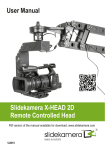
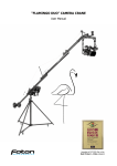
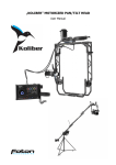
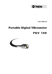
1
Command Monitoring Station 2.0 Version 1.1 July 2015 User Manual R000417 ©2012 ReconRobotics All materials contained in this document are proprietary and confidential. Reproduction and duplication, without specific written permission, is strictly prohibited. For the most up-to-date version of this manual, please visit the ReconRobotics website. ReconRobotics, Inc 7638 Washington Ave S. Eden Prairie, MN 55344 Phone: 1-866-697-6267 or 952-935-5515 Fax: 952-935-5508 Website: http://www.reconrobotics.com Email: [email protected] Within the United States, sale of the Recon Scout or Throwbot to non-Federal and non-military entities is limited to state and local police and firefighters eligible for licensing under 47 C.F.R § 90.20(a)(1) of the FCC Rules, and security personnel in Critical Infrastructure Industries as defined in the FCC Rules, 47 C.F.R § 90.7. Operation of this product by non-Federal and Non-military entities requires an FCC license. These FCC Rules do not apply to sales made outside the United States. Page 1 ReconRobotics Command Monitoring Station 2.0 Table of Contents Page Command Monitoring Station 2.0 (CMS 2.0) Inventory 3 Hardware Setup & Use 4 Channel Selection 5 CMS 2.0 Software System Requirements 6 CMS 2.0 Software Installation 7 CMS 2.0 Software Main Screen 8 CMS 2.0 Software Configuration 9 FAQs / Troubleshooting 10 Warranty 12 Page 2 Command Monitoring Station 2.0 (CMS 2.0) Inventory The Command Monitoring Station comes with the following components. Please inspect the inventory in this package to ensure that all materials are present. If any of the materials are missing, please contact [email protected] for assistance. CMS 2.0 Receiver AC Power Cord 12V DC Car Power Cord High-Gain Yagi Antenna Manfrotto™ Tripod and Antenna Mounting Hardware BNC Coaxial Cable (30 ft / 10 m) BNC Coaxial Cable (10 ft / 3 m) USB Cable CMS 2.0 Software CD-ROM Nylon Carrying Case User Manual The following items are not included: *Antenna may differ from model pictured. Laptop or desktop computer, or other A/V monitor Tools for mounting the antenna system to a vehicle RCA cables for connection to another A/V monitor Page 3 Hardware Setup & Use Follow these instructions to set up your Command Monitoring Station 2.0: Plug either power supply cord into the CMS Receiver. Plug the power supply cord into a power source – standard wall (AC) or vehicle outlet (DC), but not both at the same time. Attach the Yagi antenna to the joystick head on the tripod or use a mounting system of your choice. Attach the BNC coaxial cable to the Yagi Antenna and to the CMS Receiver. For best performance, the shorter cable included with the system will provide better signal quality to the CMS Receiver. To use with a laptop or desktop computer, install the CMS 2.0 software (see pages 6-7 of this guide for system requirements and installation). Connect the USB cable to the CMS Receiver and a high speed USB 2.0 port on the computer. To use with another video system (such as a television or monitor), connect RCA cables (not included) to your video system and to the RCA jacks on the CMS Receiver. For best performance, the Yagi antenna requires adjustments during use. Start with these guidelines and make adjustments as necessary using the trigger-activated tripod joystick to obtain the best video quality from your CMS 2.0: The antenna must be pointed in the general direction of the robot Adjust the orientation of the antenna to Pan across the horizontal – from left to right or right to left Rotate the antenna clockwise or counterclockwise Tilt the nose of the antenna up or down Raise the antenna higher or lower Page 4 Channel Selection Every ReconRobotics robot is preset to one specific channel. The channel is indicated by a sticker on the shell of the robot. When pairing an OCU and a robot, the channel designations must match identically. Robot systems are specified with different channel letters so that multiple robots can be used in the same area without interference. When using two robots, make sure they are on different channels. If two robots share a channel, such as A.2 and A, they will not work well in the same environment. Check the shell of the robot and top of the OCU for channel designation. (Robot designation depicted to the right.) The CMS 2.0 can only display video (or Audio and Video when using a Throwbot XT Audio) from one active robot at any given time. Multiple Command Monitoring Stations are required for simultaneous monitoring of multiple robots. Ensure that the selected channel is the exact same as the active robot. Indicates Audioenabled Throwbot XT Indicates Channel To change the active channel on the Command Monitoring Station, press the channel select button until the LED is lit for the desired channel. The LED will light red for channels A, B, and C; or green for channels A.2, B.2, and C.2. LED channel indicator Channel selection button Page 5 CMS 2.0 Software System Requirements Minimum System Requirements USB 2.0 equipped desktop or laptop CPU: 1 GHz RAM: 512 MB OS: Microsoft® Windows® XP w/ Service Pack 3 or above Hard Drive Disk Space: 20MB Recommended System Requirements USB 2.0 equipped desktop or laptop CPU: 2.5 GHz or faster RAM: 1 GB or more OS: Microsoft Windows 7 Graphics Card with DirectX® 10 or greater support Hard Drive Disk Space: 5 GB or more Please Note: The amount of necessary hard drive space is dependent upon the run time of the video and number of still images saved. Please Note: When using an Audio-Enabled Throwbot XT and recording using the CMS software, the Audio will automatically be recorded along with Video. Supported Operating Systems Windows XP SP3 (32-bit only) Windows Vista® Business (32-bit and 64-bit) Windows Vista Ultimate (32-bit and 64-bit) Windows 7 Home (32-bit and 64-bit) Windows 7 Professional (32-bit and 64-bit) Page 6 CMS 2.0 Software Installation To install the CMS 2.0 Software: Please close all running programs before beginning. Insert the CMS 2.0 Software CD-ROM into your CD-ROM Drive. The installation program will automatically start. Follow the steps in the installation program. The installation may require a reboot of your computer. After restarting, you should be able to run the CMS 2.0 software from a shortcut on your desktop. If you run into any problems, contact: ReconRobotics Customer Service 1-866-697-6267 Page 7 CMS 2.0 Software Main Screen CONTROL BAR: Located at the bottom of the CMS 2.0 Software main window and contains all of the controls for the following functions. RECORD VIDEO: Start recording. Once pressed, the status bar at the top of the window will indicate that the software is recording and will note the elapsed time. This icon will also change to a blue square “Stop” button. Press this button to stop recording and save the video. Videos will be saved as .wmv files. NOTE: recording will automatically capture audio as well as video. TAKE SNAPSHOT: Save a time-stamped still image of the current view. Snapshots are saved as .jpg files. VOLUME CONTROL: Adjust the audio volume heard through the CMS 2.0 software. CONFIGURE OPTIONS: Change the location where videos and snapshots are saved. You can also change the maximum length of time for each recorded segment (the default is two hours). Close the configuration window to save your changes. ACCESS INFORMATION: Display version number and instructions. Double-click on the main view to switch to a full-screen view of the video. To exit full screen, double click again, or press the escape key. To exit the program, close the main window. Page 8 CMS 2.0 Software Configuration Configuration window By clicking on the button on the main window, the configuration window appears. The configurable settings are: Save snapshots to – the directory where the snapshots ( button on main window) are saved. The default location is the Desktop of the current user. Click “Change…” to choose a different directory. Save videos to – the directory where the videos ( button on main window) are saved. The default location is the Desktop of the current user. Click “Change…” to choose a different directory. Same as snapshots checkbox will make the directory for the snapshots and videos the same. If this box is checked, the snapshots directory is used for both videos and snapshots. Switch to a new video after – When recording a video, a new video must be started at least every 2 hours. If you want to start a new video after a shorter time, you can enter the time here. Enter 0 hours to have a new video started after less than an hour. Example: [0] hours and [30] minutes would start a new video recording every 30 minutes. Page 9 FAQs / Troubleshooting Why can’t my computer detect the Command Monitoring Station? Make sure that the CMS Receiver is connected to a USB 2.0 port. Make sure that your system has updated USB host drivers. Make sure the CMS Receiver power is on. Why isn’t the application displaying video from the robot? First, make sure that your robot is active and transmitting video. Check that: The robot has been activated (pin out). The OCU screen is displaying video from the robot. Next, test your Command Monitoring Station setup. Is the CMS Receiver: Turned on? (Channel selection LED will be lit up) Set to the same channel as the active robot? Attached by cable to the Yagi antenna? Plugged into a computer with the USB cable? Why isn’t the application playing audio? Only Throwbot XT Audio robots are capable of transmitting an audio signal from the robot to the CMS 2.0 and OCU. Look for the microphone sticker on your robot to verify that audio is available: If the CMS 2.0 is not tuned to the same channel as an active audio robot, it will play static on the audio channel. Check that: The selected channel on the CMS 2.0 matches the robot channel Volume is turned up on CMS Software Volume is turned up in operating system Speakers are set up and turned on Page 10 Can I drive the robot from the CMS 2.0? No, the CMS 2.0 is designed for receiving video and audio only. How do I request service if my CMS 2.0 is still experiencing problems? If you’re experiencing problems with your CMS 2.0 that haven’t been covered by any of the questions in the FAQs, you can request service or repairs by contacting your ReconRobotics sales representative. Our technical staff will attempt to troubleshoot the problem over the phone. If necessary, ReconRobotics will issue an RMA (Return Material Authorization) for repair. In addition to your original sales receipt, you will need to provide the unit's serial number, your return shipping address, email address, and a daytime telephone number. Please Note: Depending on local system configurations, your computer may require administrator access to properly use the software. Contact your system administrator for assistance. Please Note: The following televisions are not compatible with the CMS 2.0: • Insignia NSL19Q10A (discontinued) Page 11 Warranty Warranty The manufacturer’s warranty documentation is available online at http://www.reconrobotics.com/warranty. ReconRobotics, Inc 7638 Washington Ave S. Eden Prairie, MN 55344 Phone: 1-866-697-6267 or 952-935-5515 Fax: 952-935-5508 Website: http://www.reconrobotics.com For customer service, call 866-398-1921 Or email [email protected] Page 12