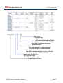
1
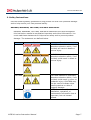
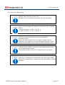
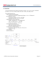
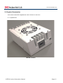
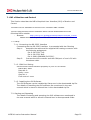
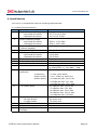
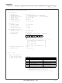
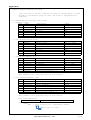
IM-T8319 Rev.01
Instruction Manual
for
Ku-band 16W BUC
[NJT8319 series]
Document Part Number: IM-T8319
Revision: 01
Issue Date: April 30, 2014
Copyright © 2014, New Japan Radio Co., Ltd. All rights reserved.
This instruction manual may not be reproduced, in part or in whole,
without the permission of New Japan Radio Co., Ltd.
The specifications and information regarding the products in this
instruction manual are subject to change without notice.
All statements, information, and recommendations in this
instruction manual are believed to be accurate but are presented
without warranty of any kind, express, or implied.
Users must take full responsibility for their application of any
products.
NJT8319 series Instruction Manual
Page 1
IM-T8319 Rev.01
General Caution
1. NJRC strives to produce reliable and high quality microwave components.
NJRC's microwave components are intended for specific applications and
require proper maintenance and handling. To enhance the performance
and service of NJRC's microwave components, the devices, machinery or
equipment into which they are integrated should undergo preventative
maintenance and inspection at regularly scheduled intervals. Failure to
properly maintain equipment and machinery incorporating these products
can result in catastrophic system failures.
2. To ensure the highest levels of reliability, NJRC products must always be
properly handled. The introduction of external contaminants (e.g. dust, oil
or cosmetics) can result in failures of microwave components.
3. NJRC offers a variety of microwave components intended for particular
applications. It is important that you select the proper component for your
intended application. You may contact NJRC's sales office or sales
representatives, if you are uncertain about the products listed in the
catalog and the specification sheets.
4. Special care is required in designing devices, machinery or equipment,
which demand high levels of reliability. This is particularly important when
designing critical components or systems whose foreseeable failure can
result in situations that could adversely affect health or safety. In
designing such critical devices, equipment or machinery, careful
consideration should be given to, amongst other things, their safety
design, fail-safe design, back-up and redundancy systems, and diffusion
design.
5. The products listed in the catalog and specification sheets may not be
appropriate for use in certain equipment where reliability is critical or
where the products may be subjected to extreme conditions. You should
consult our sales office or sales representatives before using the products
in any of the following types of equipment.
* Aerospace Equipment
* Equipment Used in the Deep Sea
* Power Generator Control Equipment (nuclear, steam, hydraulic)
* Life Maintenance Medical Equipment
* Fire Alarm/Intruder Detector
* Vehicle Control Equipment (automobile, airplane, railroad, ship, etc.)
* Various Safety Equipment
NJT8319 series Instruction Manual
Page 2
IM-T8319 Rev.01
General Caution (continued)
6. NJRC's products have been designed and tested to function within
controlled environmental conditions. Do not use products under conditions
that deviate from methods or applications specified in the catalog and
specification sheets. Failure to employ NJRC's products in the proper
applications can lead to deterioration, destruction or failure of the
products. NJRC shall not be responsible for any bodily injury, fires or
accidents, property damage or any consequential damages resulting from
the misuse or misapplication of its products. PRODUCTS ARE SOLD
WITHOUT WARRANTY OF ANY OF KIND, EITHER EXPRESS OR IMPLIED,
INCLUDING BUT NOT LIMITED TO ANY IMPLIED WARRANTY OF
MERCHANTABILITY OR FITNESS FOR A PARTICULAR PURPOSE.
NJT8319 series Instruction Manual
Page 3
IM-T8319 Rev.01
About This Instruction Manual
This instruction manual describes Ku-band 16W BUCs (Model No.: NJT8319 series)
herein referred to as "the Unit".
This instruction manual provides information and instructions for installation and
operation of the Unit.
This instruction manual is intended for use by trained field installers or system
engineers responsible for satellite networks.
Updated instruction manual may be available from NJRC's sales group
[email protected].
Contents
1. Introduction ………………………………………………………………………………
5-6
2. Safety Instructions ……………………………………………………………………
7 - 10
3. Packing List ………………………………………………………………………………
11
4. Overview ……………………………………………………………………………………
12
5. Physical Description …………………………………………………………………
13 - 16
6. Installing ……………………………………………………………………………………
17 - 21
7. GUI of Monitor and Control………………………………………………………
22
8. Maintenance ………………………………………………………………………………
23
9. Specification ………………………………………………………………………………
24 - 28
NJT8319 series Instruction Manual
Page 4
IM-T8319 Rev.01
1. Introduction
This instruction manual is for Ku-band 16W BUCs (Model No.: NJT8319 series) .
The Unit receives a reference signal (10 MHz) and an IF signal (L‐Band: 950 to
1,450 MHz or 950 to 1,700 MHz) input and transmits an RF signal (Standard Kuband: 14.0 to 14.5 GHz or Universal Ku‐band: 13.75 to 14.5 GHz) output.
The Unit comes in a single, weatherized housing rated for outdoor use. The Unit
has either an N-Type or a F-type female connector input, a WR75 waveguide with
grooved flange output, and optional MS connector for DC power input. The Unit
is operated by +48 V DC power (Range: +36 to +60 V) input.
The Unit has the function of Monitor and Control which is complied with FSK
communication and RS-232C interfaces
NJT8319 series Instruction Manual
Page 5
IM-T8319 Rev.01
The Unit has the following line-up:
NJT8319 series Instruction Manual
Page 6
IM-T8319 Rev.01
2. Safety Instructions
Use the following safety guidelines to help protect the Unit from potential damage
and to help ensure your own personal safety.
DANGER, WARNING, CAUTION, and NOTE Statements
DANGER, WARNING, CAUTION, and NOTE statements are used throughout
this instruction manual to emphasize important and critical information. You
must read these statements to help ensure safety and to prevent product
damage. The statement are defined below.
Statement
DANGER
Symbol
Description
DANGER indicates an imminently
hazardous situation which, if not
avoided, will result in death or
serious injury.
WARNING
WARNING indicates a potentially
hazardous situation which, if not
avoided, could result in death or
serious injury.
CAUTION
CAUTION indicates a potentially
hazardous situation which, if not
avoided, could result in minor or
moderate injury. CAUTION may
also be used to indicate other
unsafe practices or risks of
property damage.
NOTE is used to notify of
installation, operation, or
maintenance information that is
important, but not hazardrelated.
NOTE
NJT8319 series Instruction Manual
Page 7
IM-T8319 Rev.01
Symbol
Description
GENERIC HAZARD
ELECTRIC HAZARD
HOT SURFACE
MOVING PARTS
When installing the Unit, observe the following safety guidelines.
2.1. Safety Statements
1. Opening / Removing
DO NOT dismantle this product.
Dismantlement may cause malfunction and electric shock.
2. Input Voltage
Only input a voltage within the range indicated in specified
voltage.
DO operate at the input voltage of +36 to +60 V DC power.
NJT8319 series Instruction Manual
Page 8
IM-T8319 Rev.01
3. RF Radiation
A radiation hazard exists if the BUC is operated with its RF
signal output unterminated.
DO NOT operate the BUC without a load or termination
attached to the RF signal output.
4. High Temperatures
DO NOT touch the body, especially fins, during operating the
Unit.
High touch temperatures may exist, depending on load
conditions.
5. Fan
DO NOT insert your finger into the fan to avoid injury.
DO NOT insert any objects into the fan. Keep any objects away
from the fan.
Incorrect usage may cause injury to self or others.
6. Input Level
DO NOT input an IF signal over the range of +13 dBm
maximum and a reference signal within the range of -5 to +5
dBm.
7. Operating Temperature.
Operate the Unit within the ambient temperature range of -40
to +75 degree C, but the performance guarantee temperature
range is -40 to +55 degree C.
NJT8319 series Instruction Manual
Page 9
IM-T8319 Rev.01
2.2. Instruction Statements
1. Mounting
2. Connector
DO NOT block the fins and air flow.
Normally the Unit should be mounted with fan face down.
When attaching cable, DO tighten as connector with following
torque:
N-type connector, 0.68 to 1.13 N・m
F-type connector, 0.39 to 0.49 N・m
3. Weatherproof
The Unit is mounted outdoors must be adequately
weatherproofed.
Ensure the waveguide joints are properly sealed with the
supplied o-ring (gasket). Use self-amalgamating tape to seal
connectors and cable entry points from the connector to the
4. Fan
5. Warranty
The fan has its lifetime. The fan is to be replaced with a new
one at appropriate interval.
The recommendation interval of replacement is five years.
Opening or removing any component (e.g. label, and screws)
without fan equipments or sealed area will immediately void the
warranty.
NJT8319 series Instruction Manual
Page 10
IM-T8319 Rev.01
3. Packing List
The Unit is shipped in a single shipping container with the following content:
No.
1.
Qty
1 unit
2.
1 set
3.
4.
1 sheet
( 1 pc )
Description
BUC:
NJT8319N
NJT8319F
NJT8319NM
NJT8319FM
NJT8319NK
NJT8319FK
NJT8319NMK
NJT8319FMK
NJT8319NMR
NJT8319FMR
NJT8319UN
NJT8319UF
NJT8319UNM
NJT8319UFM
NJT8319UNK
NJT8319UFK
NJT8319UNMK
NJT8319UFMK
NJT8319UNMR
OR
NJT8319UFMR
Accessory:
Qty(4), Hexagon Socket Head Bolt (M4x10)
Qty(1), Hexagon Wrench Key (M4)
Qty(2), Phillips-head Screw (M6x10)
Qty(1), O-ring
Date sheet
Mating MS Connector:
Part Number: PT06E-14-12S (470)
* MS connector is enclosed in the shipping container
the only MS Connector models
NJT8319 series Instruction Manual
Page 11
IM-T8319 Rev.01
4. Overview
The Unit transmits an RF signal (Universal Ku‐band: 13.75 to 14.5 GHz / Standard
Ku-band: 14.0 to 14.5 GHz) output with up to 16W (+42 dBm) linear.
The unique features are
・ High Temperature Operating:
* Operation Guarantee Temperature Range: -40 to +75 degree C
・ RF Frequency Line-up:
* Universal Ku-band: 13.75 to 14.5 GHz
* Standard Ku-band: 14.0 to 14.5 GHz
・ High Efficiency & Low Distortion.
* P1dB: +42 dBm min. over temperature
* IM3: -28 dBc @ Pout = +39 dBm
* Power Consumption: 160 W typ.
・ Monitor & Control Line-up
* FSK Communication M&C
* RS-232C Interface Serial M&C
・ Smaller Size & Lighter Weight
* Dimension: 180 (L) x 130 (W) x 80 (H) mm
* Weight: 2.4 kg
・ LED Indicator
・ RoHS Compliance
Block Diagram
NJT8319 series Instruction Manual
Page 12
IM-T8319 Rev.01
5. Physical Description
This section describes appearance and outline for the Unit.
5.1. Appearance
Overall Picture
NJT8319 series Instruction Manual
Page 13
IM-T8319 Rev.01
5.2. Outline Drawing
NJT8319 series Instruction Manual
Page 14
IM-T8319 Rev.01
5.3. Description of Connectors, and LEDs
Item
N-type
or
F-type
Female
Connector
Description
IF Signal Input
Reference Signal
Input
Purpose
The Unit receives an IF signal (950 to
1,450 MHz or 950 to 1,700 MHz) via
this connector.
The Unit receives a reference signal
(10 MHz) via this connector.
FSK
Communication
M&C Signal
Circular
Connector
(MS
Connector)
FSK Communication M&C models are
only equipped.
The Unit receives / transmits the M&C
signal with the FSK modulation via this
connector.
DC Power Input *1
The Unit is required to supply +36 to
+60 V DC power via this connector.
DC Power Input *1
MS Connector models are only
The Unit is required to supply +36 to
+60 V DC power via Pin# J and K in
this connector.
RS-232C Interface
RS-232C Interface M&C models are
M&C Signal
only equipped.
The Unit receives / transmits the M&C
signal with the RS-232C interface Pin#
G, H and K in this connector.
Connector Information
Part No.: PT02E-14-12P (025)
Mating connector: PT06E-14-12S (470)
Assignment:
* Pin G: RS-232C TxD and Pin H: RS-232C RxD are available for
only RS-232C Interface M&C models.
* Do not connect the pins for N.C. and not using pins with the
cable wires.
NJT8319 series Instruction Manual
Page 15
IM-T8319 Rev.01
Item
WR-75
Description
RF Output
LED
Indicator
Local Unlock Alarm
Grounded
Hole
M6 hole
Purpose
The Unit transmits an RF signal (14.0
to 14.5 GHz or 13.75 to 14.5 GHz) via
this waveguide.
GREEN: L.O. locked
RED: L.O. unlocked (or no reference
signal)
Common chassis ground
*1: MS Connector models are available to apply DC voltage via Circular
Connector (MS Connector) or N-/F-type Female Connector.
DO NOT apply DC voltage via both Circular Connector (MS
Connector) and N-/F-type Female Connector.
If DC voltage is applied on both connectors, it may damage the
unit or the unit may not operate properly.
NJT8319 series Instruction Manual
Page 16
IM-T8319 Rev.01
6. Installing
This section describes basic installation for the Unit.
6.1. Mounting Configuration
The Unit can be mounted in the feed horn of the satellite antenna.
6.1.1. Guidelines for Attachment of OMT
When attaching the OMT or the filter, you should follow the following
steps:
Step 1:
Verify that the o-ring groove on the
waveguide flange of the Unit is clean.
Insert the enclosed o-ring (gasket)
the groove as shown.
Step 2:
Secure the OMT or the filter to the Unit using the supplied
enclosed bolts with 1.15 to 1.4 N・m torque as shown, when the
thickness of the flange of the OMT or the filter is 3.5 to 5.0
mm.
When the thickness is not 3.5 to 5.0 mm, you should prepare
6.1.2. Guidelines for Mounting
When mounting on the OMT or the filter, you should follow the following
cautions:
・ DO NOT block the fins and air flow.
・ Normally the Unit should be mounted with fan face down.
NJT8319 series Instruction Manual
Page 17
IM-T8319 Rev.01
6.2. Connecting System
The Unit is connected two cables:
・ Coaxial Cable
・ Power Cable
・ Wire for Common Chassis Ground / Earthing
・ M&C Signal Cable
6.2.1. Connecting Coaxial Cable
The Unit receives an IF signal and a reference signal via coaxial cable from
modem, is required to supply +36 to +60 V DC power , receives an FSK
communication M&C signal.
Connecting the coaxial cable is proceeded with the following steps:
Step 1:
Connect the coaxial cable with N-type or F-type male
connectors to the coaxial connector equipped with the Unit
under following torque:
N-type connector, 0.68 to 1.13 N・m
F-type Connector, 0.39 to 0.49 N・m
Step 2:
Use self-amalgamating tape to seal connector and cable entry
points from the connector to the cable sheath.
Only input a voltage within the range indicated in specified
voltage.
DO operate at the input voltage of +36 to +60 V DC power at
the coaxial connector on the Unit.
DO NOT input an IF signal over the range of +13 dBm
maximum and a reference signal within the range of -5 to +5
dBm.
Connecting the coaxial cable
NJT8319 series Instruction Manual
Page 18
IM-T8319 Rev.01
6.2.2. Connecting Power Cable
The Unit is required to supply +36 to +60 V DC power via power cable
from modem or a DC power supply unit with the exception of only IF
connecter supplied models.
Connecting the power cable is proceeded with the following steps:
Step 1:
Assemble the power cable and the supplied MS mating
connector with the following assignment:
Pin J: Prime (+48 V DC Power)
Pin K: Prime Return
* Do not connect the pins for N.C. and not using pins with the cable wires.
Step 2:
Step 3:
Connect the power cable above to MS connector equipped with
a bayonet locked status.
Use self-amalgamating tape to seal connector and cable entry
points from the connector to the cable sheath.
Only input a voltage within the range indicated in specified
voltage.
DO operate at the input voltage of +36 to 60 V DC power at
the coaxial connector on the Unit.
DO NOT apply DC voltage via both MS Connector and N-/F-type
Female Connector.
If DC voltage is applied on both connectors, it may damage the
unit or the unit may not operate properly.
Connecting the power cable
NJT8319 series Instruction Manual
Page 19
IM-T8319 Rev.01
6.2.3. Wire for Common Chassis Ground / Earthing
The Unit can be had the chassis ground of the other equipment (e.g.
antenna) in common or earthing.
Connecting the wire for common chassis ground / earthing is proceeded
with the following steps:
Step 1:
Connect the grounding/ earthing wire from ground on the other
equipment or earthing point to the ground hole on connector or
waveguide sides with M6 screw.
Connect the grounding/ earthing wire
OR
Connect the grounding/ earthing wire
NJT8319 series Instruction Manual
Page 20
IM-T8319 Rev.01
6.2.4. Connecting M&C Signal Cable
The Unit is required to supply RS-232C interface signal via signal cable
from modem or M&C equipment in case that it is RS-232C interface M&C
models.
Connecting the M&C signal cable is proceeded with the following steps:
Step 1:
Assemble the M&C signal cable and the supplied MS mating
connector with the following assignment:
Pin G: RS-232C TxD
Pin H: RS-232C RxD
Pin K: GND COMMON (RS-232C)
* Do not connect the pins for N.C. and not using pins with the cable wires.
Step 2:
Step 3:
Connect the M&C signal cable above to MS connector equipped
with a bayonet locked status.
Use self-amalgamating tape to seal connector and cable entry
points from the connector to the cable sheath.
Connecting the M&C signal cable
NJT8319 series Instruction Manual
Page 21
IM-T8319 Rev.01
7. GUI of Monitor and Control
This Section describes the NJR's Graphical User Interface (GUI) of Monitor and
Control.
The NJR's GUI is available for the RS-232C Interface M&C models.
The GUI uses the BUC-EP001 software which can be downloaded from the
following NJR's website.
・ Website:
http://mc.njr.co.jp/eng/products/vsat/ku-buc/8w_2.html
Please download a zip file of the GUI software and decompress this
7.1. Setup
7.1.1. Connecting the RS-232C Interface
Connecting the the RS-232C Interface is proceeded with the following
Step 1:
Assemble the cable and the supplied MS mating connector with
the following assignment:
Pin G: RS-232C TxD
Pin H: RS-232C RxD
Pin K: GND COMMON (RS-232C)
Step 2:
Connect the MS connector and the COM port of user's PC with
the above cable.
7.1.2. COM Port Setting
Set the serial communication property of your PC as follows.
Baud rate: 9600
Data bit: 8
Parity: none
Stop bit: 1
Flow control: none
7.1.3. Installing the GUI Software
The GUI Software can be installed by Setup.exe in the downloaded zip file.
The details of Installing the GUI software are mentioned in the user
manual which is stored in Manual.htm in the downloaded zip file.
7.2. Starting and Operating
The details of starting and operating the GUI software are mentioned in
the user manual which is stored in Manual.htm in decompressed folder.
NJT8319 series Instruction Manual
Page 22
IM-T8319 Rev.01
8. Maintenance
This Section describes basic maintenance for the Unit.
8.1. Fan Field Replacement
The Unit is Forced Air by fan for cooling.
The fan has its lifetime. The fan is to be replaced with a new
one at appropriate interval.
The recommendation interval of replacement is five years.
The fan of the Unit stop and does not operate normally, you need to replace a
new fan by yourself in field. And the fan is to be replaced with a new one at
five years interval.
Contact to us by phone, fax, or email, when a new fan for replacement is
needed.
+81-49-278-1270
・ Telephone:
+81-49-278-1234
・ Fax:
・ Email:
[email protected]
NJT8319 series Instruction Manual
Page 23
IM-T8319 Rev.01
9. Specifications
The Unit is in compliance with the following specifications:
9.1. Electrical Specifications
No.
Item
1.
Output Frequency Range
<Universal Ku-band>
<Standard Ku-band>
Input Frequency Range
2.
<Universal Ku-band>
<Standard Ku-band>
Maximum IF Input Level
3.
(without damage)
4.
Conversion Type
L.O. Frequency
5.
<Universal Ku-band>
<Standard Ku-band>
6.
Frequency Sense
Output Power @ 1dB G.C.P.
7.
Linear Gain
8.
9.
IM3
10.
Requirement for External
Reference
[Frequency]
[Input Power]
[Phase Noise]
11.
L.O. Phase Noise
12.
Input Impedance
<N-type Model>
<F-type Model>
Input VSWR
Output VSWR
Output Load VSWR for Non
Damage
13.
14.
15.
NJT8319 series Instruction Manual
Specifications
13.75 to 14.5 GHz
14.0 to 14.5 GHz
950 to 1,700 MHz
950 to 1,450 MHz
+13 dBm max.
Single, fixed L.O.
12.80 GHz
13.05 GHz
Positive
+42 dBm min. over temperature
68 dB nom., 62 dB min.
-28 dBc typ., -24 dBc max.
@ total power <= +42 dBm - 3 dB
10 MHz (sine-wave)
-5 to +5 dBm @ Input port
-125 dBc/Hz max. @ 100 Hz
-135 dBc/Hz max. @ 1 kHz
-140 dBc/Hz max. @ 10 kHz
-60 dBc/Hz max. @ 100 Hz
-70 dBc/Hz max. @ 1 kHz
-80 dBc/Hz max. @ 10 kHz
-90 dBc/Hz max. @ 100 kHz
-100 dBc/Hz max. @ 1MHz
50 ohms nom.
75 ohms nom.
2 : 1 max.
2 : 1 max.
2 : 1 max.
Page 24
IM-T8319 Rev.01
No.
16.
Item
DC Power Requirement
[Voltage Range]
[Power Consumption]
17.
Mute
18.
LED Indicator
19.
Monitor and Control
<FSK Communication M&C>
[Interface]
[Functions]
[Performance
Specifications
+48 VDC (+36 to +60 VDC)
140 W typ. @ No IF signal
160W typ., 180 W max.
@ Pout = +42 dBm
Shut off the HPA in case of L.O.
unlocked
GREEN: L.O. locked
RED: L.O. unlocked
(or no 10 MHz reference signal)
650kHz FSK Signal on IF Connector
Monitor:
Tx Output Power / Temperature
/ Tx Status / Alarm (Over
temperature *2 / L.O. unlock)
/ Step Attenuator
Control:
Transmit On/Off / Step Attenuator
Tx Output Power:
Detector Range: 15 dB (up to P1dB)
Reading Accuracy: +/- 1.0 dB
Step Attenuator:
Attenuator Range: 0 to 15.5 dB
Attenuator Step: 0.5 dB
* Details are mentioned on Appendix of
“Monitor & Control Specifications for FSK
Communications Interface”.
NJT8319 series Instruction Manual
Page 25
IM-T8319 Rev.01
No.
19.
Item
Monitor and Control
<RS-232C Interface M&C>
[Interface]
[Functions]
[Performance
Specifications
RS-232C Interface on MS connector
Monitor:
Tx Output Power / Temperature
/ Tx Status / Alarm (Over
temperature *2 / L.O. unlock)
/ Step Attenuator
Control:
Transmit On/Off / Step Attenuator
Tx Output Power:
Detector Range: 15 dB (up to P1dB)
Reading Accuracy: +/- 1.0 dB
Step Attenuator:
Attenuator Range: 0 to 15.5 dB
Attenuator Step: 0.5 dB
* Details are mentioned on Appendix of
“Monitor & Control Specifications for RS232C Interface”.
*2: Regardless of cooling fan status, the unit will operate until status
of over temperature which turn out at internal temperature of
around 120 °C, and the Mute and Alarm will function at status of
over temperature.
NJT8319 series Instruction Manual
Page 26
IM-T8319 Rev.01
9.2. Mechanical Specifications:
No.
Item
1.
Input Interface
[IF Connector]
[DC Input *3]
Specifications
N-type or F-type, female connector
IF / Ref. / FSK M&C Signal (/ DC) Input
IF Connector or MS Connector
- MS connector Part No.: PT02E-14-12P (025)
Mating connector:
PT06E-14-12S (470)
Assignment:
2.
Output Interface
3.
4.
Cooling
Dimension & Housing
without Interface Connector
(L)
(W)
(H)
Weight
5.
* Pin G: RS-232C TxD and Pin H: RS232C RxD are available for only RS-232C
Interface M&C models.
* Do not connect the pins for N.C. and
not using pins with the cable wires.
Waveguide, WR75
with Grooved Flange
Forced-air-cooled
180 mm [7.09"]
130 mm [5.12"]
80 mm [3.15"]
2.4 kg [5.3 lbs]
*3: MS Connector models are available to apply DC voltage via MS
Connector or N-/F-type Female Connector.
DO NOT apply DC voltage via both MS Connector and N-/F-type
Female Connector.
If DC voltage is applied on both connectors, it may damage the
unit or the unit may not operate properly.
NJT8319 series Instruction Manual
Page 27
IM-T8319 Rev.01
9.3. Environmental Specification:
No.
Item
1.
Temperature Range (ambient)
[Operating]
[Storage]
Specifications
Operation Guarantee: -40 to +75 °C
Performance Guarantee: -40 to +55 °C
-40 to +75 °C
0 to 100 %
15,000 feet (4,572 m)
2.
3.
4.
Humidity
Altitude
Vibration
5.
Shock
6.
Dustproof / Waterproof
7.
8.
Regulatory Compliance
CE / EMC Directive (2004/108/EC)
Comply with RoHS (Restricting the use of Hazardous Substances)
directives
NJT8319 series Instruction Manual
5 G [49.03 m/s2]
(3 axis, 50 Hz to 2 kHz)
1 mm p-p
(3 axis, 5 to 50 Hz)
30 G [294.20 m/s2] (3 axis)
IP67 (IEC 60529)
Page 28
Appendix)
Monitor & Control Specifications for FSK Communications Interface
Rev.
3.0
June 14 2013
1. FSK Communications Specifications
(1) Transmitter
a. Frequency
b. FSK deviation
c. Deviation tolerance
d. Output Level
e. Output impedance
f. Start Tone
g. Start Tone Time
650 kHz +/-5%
+/- 60 kHz Nominal (+60 kHz mark)
+/- 50 kHz minimum ; +/-70 kHz maximum
-5 to –15 dBm
50 Ohm
710 kHz
10 ms minimum
(2) Receiver
a. Locking range
b. Input impedance
c. Input Sensitivity
+/- 32.5 kHz
50 Ohm
-15 dBm
(3) Transmission Protocol
a. Operation Mode
b. Transfer Rate
c. Data Format
Legacy-Binary
9600 bit/s
1 start bit, 8 data bits, 1 stop bit
No Parity
ST D0 D1 D2 D3 D4 D5 D6 D7 SP
Transmit
(The least significant bit (LSB) is sent first.)
d. Maximum Response Time
e. Massage Rate
ST: Start bit (Status "L")
D0: Data(LSB)
--D7: Data(MSB)
SP: Stop bit (Status "H")
50 ms
1 every 20 ms
2. Packet Format
(1) Byte Configuration
a. Data Packet Length
b. Byte Configuration
7 Bytes
Byte Command (IDU to BUC)
1st
BUC Address (*1)
2nd
Command
3rd
Data Byte 1
4th
Data Byte 2
5th
Data Byte 3
6th
Data Byte 4
7th
Check Sum (*3)
Response (BUC to IDU)
BUC Address (*2)
Data Byte 1
Data Byte 2
Data Byte 3
Data Byte 4
Data Byte 5
Check Sum (*3)
*1: Initial setting of a BUC address is 0x01.
*2: Responder address is shifted left by 4 bits.
*3: Algebraic sum of bytes 1 through 6.
Spare bytes are always filled with 0xAA (10101010).
FSK-M&C_rev3.0
New Japan Radio Co., Ltd.
1/4
Appendix)
3. Command & Response Message Structure
The last state of the BUC condition is stored to inside memory, so when
the BUC is re-turned DC power on again, the state is reproduced last
condition.
(1) Command Message Structure (IDU to BUC)
a. Request Status 1
Byte
Name
Description
1
Address
Address of BUC
2
Command
Request Status 1
3
Data Byte 1
Not used
4
Data Byte 2
Not used
5
Data Byte 3
Not used
6
Data Byte 4
Not used
7
Checksum
Algebraic sum of bytes 1 - 6
Value
0x01 (to 0x0F)
0x01
0xAA
0xAA
0xAA
0xAA
b. Set Transmit On/Off State
Byte
Name
Description
1
Address
Address of BUC
2
Command
Tx On/Off
3
Data Byte 1
Tx Control
4
Data Byte 2
Not used
5
Data Byte 3
Not used
6
Data Byte 4
Not used
7
Checksum
Algebraic sum of bytes 1 - 6
Value
0x01 (to 0x0F)
0x02
Off:0x00/On:0x01
0xAA
0xAA
0xAA
c. Change BUC Address (N/A)
Byte
Name
Description
1
Address
Address of BUC
2
Command
Change Address
3
Data Byte 1
New Address
4
Data Byte 2
Not used
5
Data Byte 3
Not used
6
Data Byte 4
Not used
7
Checksum
Algebraic sum of bytes 1 - 6
Value
0x01 (to 0x0F)
0x03
0x01 to 0x0F
0xAA
0xAA
0xAA
This command is not applicabe (N/A) in this version.
d. Set Carrier Frequency
Byte
Name
1
Address
2
Command
3
Data Byte 1
4
Data Byte 2
5
Data Byte 3
6
Data Byte 4
7
Checksum
(N/A)
Description
Address of BUC
Set Carrier Frequency
Carrier Frequency
Carrier Frequency
Not used
Not used
Algebraic sum of bytes 1 - 6
Value
0x01 (to 0x0F)
0x04
MSbyte
LSbyte
0xAA
0xAA
This command is not applicabe (N/A) in this version.
Data Field Definition
Carrier Frequency
Unsigned integer in MHz
ex).
14000 MHz
: 36 B0 (Convert into a hexadecimal number)
Data byte 1 is 0x36
FSK-M&C_rev3.0
New Japan Radio Co., Ltd.
2/4
Appendix)
e. Set Attenuator
Byte
Name
1
Address
2
Command
3
Data Byte 1
4
5
6
7
Data Byte 2
Data Byte 3
Data Byte 4
Checksum
Description
Address of BUC
Set Attenuator
Attenuator Selection 1 or 2
Setting Att. in 10dB digit
Setting Att. in 1dB digit
Setting Att. bit in 0.5dB digit
Algebraic sum of bytes 1 - 6
Value
0x01 (to 0x0F)
0x05
Att.1 0x01
Att.2 0x02
0x00 or 0x01
0x00 to 0x09
0x00 or 0x05
*1
*2
*2
*2
*1 Att.1 is available, Att.2 is not avalable.
*2 Dynamic range and step size of the step attenuator: 15.5dB in 0.5dB step
ex) 12.5dB : Data byte 2 is 0x01
Data byte 3 is 0x02
Data byte 4 is 0x05
f. Request
Byte
1
2
3
4
5
6
7
Status 2
Name
Address
Command
Data Byte 1
Data Byte 2
Data Byte 3
Data Byte 4
Checksum
Description
Address of BUC
Request Status 2
Attenuator Selection 1 or 2
Not used
Not used
Not used
Algebraic sum of bytes 1 - 6
Value
0x01 (to 0x0F)
0x06
Att.1 0x01
Att.2 0x02
0xAA
0xAA
0xAA
(2) Response Message Structure (BUC to IDU)
a. Request Status 1
Byte
Name
Description
Value
1
Address
Address of BUC shifted left by 4
0x10 (to 0xF0)
*1
2
Level Byte 1
MSbyte of Tx Output Power
*1
3
Level Byte 2
LSbyte of Tx Output Power
*2
4
Temperature
Temperature in deg. C
5
Status Byte 1 Bit 0: Temperature Out-of-Range
1:Fail , 0:Normal
Bit 1: PLL Out-of-Lock
1:Fail , 0:Normal
Bit 2: Checksum Error
1:Error , 0:Normal
Bit 3: Tx Status
1:Tx On , 0:Tx Off
*3
Bits 4 thru 7: BUC Power Class
0x1 to 0xA
6
Status Byte 2 Bits 0 - 3: Not used
Fixed 0xA
Bits 4 - 7: Software Version
0x0 to 0xF
7
Checksum
Algebraic sum of bytes 1 - 6
*1 Data Field Definition
Output power is the number which changed hexadecimal data into the decimal
number and was divided by 100.
ex).
Output Power Data
Output Power
Data byte 1 is 0x10
0x1036 →
+41.50 dBm
Data byte 2 is 0x36
*2 Data Field Definition
Temperature data is -128 deg.C to +127 deg.C in two's complement.
(1 deg.C step).
ex).
When BUC Temperature is -40C, Temperature data is
*3 BUC Power Class
Value
0x1
0x2 0x3
0x4
0x5
0x6
0x7
0x8
0x9
0xA
Power
2W
4W
5W
8W
10w
16W
20W
25W
40W
60W
FSK-M&C_rev3.0
New Japan Radio Co., Ltd.
3/4
Appendix)
b. Set Transmit
Byte
Name
1
Address
2
Command
3
Data Byte
4
Data Byte
5
Data Byte
6
Data Byte
7
Checksum
1
2
3
4
Description
Address of BUC shifted left by 4
Tx On/Off
Tx Control
Not used
Not used
Not used
Algebraic sum of bytes 1 - 6
c. Change BUC Address (N/A)
Byte
Name
Description
1
Address
Address of BUC shifted left by 4
2
Command
Change Address
3
Data Byte 1
New Address
4
Data Byte 2
Not used
5
Data Byte 3
Not used
6
Data Byte 4
Not used
7
Checksum
Algebraic sum of bytes 1 - 6
Value
0x10 (to 0xF0)
0x02
Off:0x00/On:0x01
0xAA
0xAA
0xAA
Value
0x10 (to 0xF0)
0x03
0x01 to 0x0F
0xAA
0xAA
0xAA
This command is not applicabe (N/A) in this version.
d. Set Carrier Frequency
Byte
Name
1
Address
2
Command
3
Data Byte 1
4
Data Byte 2
5
Data Byte 3
6
Data Byte 4
7
Checksum
(N/A)
Description
Address of BUC shifted left by 4
Set Carrier Frequency
Carrier Frequency
Carrier Frequency
Not used
Not used
Algebraic sum of bytes 1 - 6
Value
0x10 (to 0xF0)
0x04
MSbyte
LSbyte
0xAA
0xAA
This command is not applicabe (N/A) in this version.
e. Set Attenuator
Byte
Name
1
Address
2
Command
3
Data Byte 1
4
5
6
7
f. Request
Byte
1
2
3
4
5
6
7
Data Byte 2
Data Byte 3
Data Byte 4
Checksum
Status 2
Name
Address
Command
Data Byte 1
Data Byte 2
Data Byte 3
Data Byte 4
Checksum
Description
Address of BUC shifted left by 4
Set Attenuator
Attenuator Selection 1or 2
Set Att. bit in
Set Att. bit in
Set Att. bit in
Algebraic sum of
10 dB digit
1 dB digit
0.5 dB digit
bytes 1 - 6
Description
Address of BUC
Request Status 2
Attenuator Selection 1or 2
Set Att. bit in
Set Att. bit in
Set Att. bit in
Algebraic sum of
10 dB digit
1 dB digit
0.5 dB digit
bytes 1 - 6
Value
0x10 (to 0xF0)
0x05
Att.1 0x01
Att.2 0x02
0x00 or 0x01
0x00 to 0x09
0x00 or 0x05
Value
0x10 (to 0xF0)
0x08
Att.1 0x01
Att.2 0x02
0x00 or 0x01
0x00 to 0x09
0x00 or 0x05
FSK-M&C_rev3.0
New Japan Radio Co., Ltd.
4/4
Appendix)
Monitor & Control Specifications for RS-232C Interface
Rev.
2.3
July 25 2013
1. RS-232C Link Specificatons
(1) Transmission Protocol
a. Operation Mode
b. Transfer Rate
c. Data Format
Binary
9600 bit/s
1 start bit, 8 data bits, 1 stop bit
No Parity
ST D0 D1 D2 D3 D4 D5 D6
D7 SP
Transmit
(The least significant bit (LSB) is sent first.)
ST: Start bit
D0: Data(LSB)
--D7: Data(MSB)
SP: Stop bit
2. Packet Format
(1) Byte Configuration
a. Data Packet Length
b. Byte Configuration
7 Bytes
Byte Command (IDU to BUC)
1st
BUC Address (*1)
Command
2nd
Data Byte 1
3rd
Data Byte 2
4th
Data Byte 3
5th
Data Byte 4
6th
7th
Check Sum (*3)
Response (BUC to IDU)
BUC Address (*2)
Data Byte 1
Data Byte 2
Data Byte 3
Data Byte 4
Data Byte 5
Check Sum (*3)
*1: Initial setting of a BUC address is 0x01.
*2: Responder address is shifted left by 4 bits.
*3: Algebraic sum of bytes 1 through 6.
Spare bytes are always filled with 0xAA (10101010).
New Japan Radio Co., Ltd.
RS232C-M&C_rev2.3
1/4
Appendix)
3. Command & Response Message Structure
The last state of the BUC condition is stored to inside memory, so when
the BUC is re-turned DC power on again, the state is reproduced last
condition.
(1) Command Message Structure (IDU to BUC)
a. Request Status 1
Byte
Name
Description
1
Address
Address of BUC
2
Command
Request Status 1
3
Not used
Data Byte 1
4
Not used
Data Byte 2
5
Not used
Data Byte 3
6
Not used
Data Byte 4
7
Checksum
Algebraic sum of bytes 1 - 6
Value
0x01 (to 0x0F)
0x01
0xAA
0xAA
0xAA
0xAA
b. Set Transmit On/Off State
Byte
Name
Description
1
Address
Address of BUC
2
Command
Tx On/Off
3
Tx Control
Data Byte 1
4
Not used
Data Byte 2
5
Not used
Data Byte 3
6
Not used
Data Byte 4
7
Checksum
Algebraic sum of bytes 1 - 6
Value
0x01 (to 0x0F)
0x02
Off:0x00/On:0x01
0xAA
0xAA
0xAA
c. Change BUC Address (N/A)
Byte
Name
Description
1
Address
Address of BUC
2
Command
Change Address
3
New Address
Data Byte 1
4
Not used
Data Byte 2
5
Not used
Data Byte 3
6
Not used
Data Byte 4
7
Checksum
Algebraic sum of bytes 1 - 6
Value
0x01 (to 0x0F)
0x03
0x01 to 0x0F
0xAA
0xAA
0xAA
This command is not applicabe (N/A) in this version.
d. Set Carrier Frequency
Byte
Name
1
Address
2
Command
3
Data Byte 1
4
Data Byte 2
5
Data Byte 3
6
Data Byte 4
7
Checksum
(N/A)
Description
Address of BUC
Set Carrier Frequency
Carrier Frequency
Carrier Frequency
Not used
Not used
Algebraic sum of bytes 1 - 6
Value
0x01 (to 0x0F)
0x04
MSbyte
LSbyte
0xAA
0xAA
This command is not applicabe (N/A) in this version.
Data Field Definition
Carrier Frequency
Unsigned integer in MHz
ex).
14000 MHz
: 36 B0 (Convert into a hexadecimal number)
Data byte 1 is 0x36
New Japan Radio Co., Ltd.
RS232C-M&C_rev2.3
2/4
Appendix)
e. Set Attenuator
Byte
Name
1
Address
2
Command
3
Data Byte 1
4
5
6
7
Data Byte 2
Data Byte 3
Data Byte 4
Checksum
Description
Address of BUC
Set Attenuator
Attenuator Selection 1 or 2
Setting Att. in 10dB digit
Setting Att. in 1dB digit
Setting Att. bit in 0.5dB digit
Algebraic sum of bytes 1 - 6
Value
0x01 (to 0x0F)
0x05
Att.1 0x01
Att.2 0x02
0x00 or 0x01
0x00 to 0x09
0x00 or 0x05
*1
*2
*2
*2
*1 Att.1 is available, Att.2 is not avalable.
*2 Dynamic range and step size of the step attenuator: 15.5dB in 0.5dB step
ex) 12.5dB : Data byte 2 is 0x01
Data byte 3 is 0x02
Data byte 4 is 0x05
f. Request
Byte
1
2
3
4
5
6
7
Status 2
Name
Address
Command
Data Byte 1
Description
Address of BUC
Request Status 2
Attenuator Selection 1 or 2
Data Byte 2
Data Byte 3
Data Byte 4
Checksum
Not used
Not used
Not used
Algebraic sum of bytes 1 - 6
Value
0x01 (to 0x0F)
0x06
Att.1 0x01
Att.2 0x02
0xAA
0xAA
0xAA
(2) Response Message Structure (BUC to IDU)
a. Request Status 1
Byte
Name
Description
Value
1
Address
0x10 (to 0xF0)
Address of BUC shifted left by 4
*1
2
MSbyte of Tx Output Power
Level Byte 1
*1
3
LSbyte
of
Tx
Output
Power
Level Byte 2
*2
4
Temperature
Temperature in deg. C
5
1:Fail , 0:Normal
Status Byte 1 Bit 0: Temperature Out-of-Range
1:Fail , 0:Normal
Bit 1: PLL Out-of-Lock
1:Error , 0:Normal
Bit 2: Checksum Error
1:Tx On , 0:Tx Off
Bit 3: Tx Status
*3
0x1 to 0xA
Bits 4 thru 7: BUC Power Class
6
Fixed 0xA
Status Byte 2 Bits 0 - 3: Not used
0x0 to 0xF
Bits 4 - 7: Software Version
7
Checksum
Algebraic sum of bytes 1 - 6
*1 Data Field Definition
Output power is the number which changed hexadecimal data into the decimal
number and was divided by 100.
ex).
Output Power Data
Output Power
Data byte 1 is 0x10
0x1036 →
+41.50 dBm
Data byte 2 is 0x36
*2 Data Field Definition
Temperature data is -128 deg.C to +127 deg.C in two's complement.
(1 deg.C step).
ex).
When BUC Temperature is -40C, Temperature data is
*3 BUC Power Class
Value
0x1
0x2 0x3
0x4
0x5
0x6
0x7
0x8
0x9
0xA
Power
2W
4W
5W
8W
10w
16W
20W
25W
40W
60W
New Japan Radio Co., Ltd.
RS232C-M&C_rev2.3
3/4
Appendix)
b. Set Transmit
Byte
Name
1
Address
2
Command
3
Data Byte
4
Data Byte
5
Data Byte
6
Data Byte
7
Checksum
1
2
3
4
Description
Address of BUC shifted left by 4
Tx On/Off
Tx Control
Not used
Not used
Not used
Algebraic sum of bytes 1 - 6
c. Change BUC Address (N/A)
Byte
Name
Description
1
Address
Address of BUC shifted left by 4
2
Command
Change Address
3
New Address
Data Byte 1
4
Not used
Data Byte 2
5
Not used
Data Byte 3
6
Not used
Data Byte 4
7
Checksum
Algebraic sum of bytes 1 - 6
Value
0x10 (to 0xF0)
0x02
Off:0x00/On:0x01
0xAA
0xAA
0xAA
Value
0x10 (to 0xF0)
0x03
0x01 to 0x0F
0xAA
0xAA
0xAA
This command is not applicabe (N/A) in this version.
d. Set Carrier Frequency
Byte
Name
1
Address
2
Command
3
Data Byte 1
4
Data Byte 2
5
Data Byte 3
6
Data Byte 4
7
Checksum
(N/A)
Description
Address of BUC shifted left by 4
Set Carrier Frequency
Carrier Frequency
Carrier Frequency
Not used
Not used
Algebraic sum of bytes 1 - 6
Value
0x10 (to 0xF0)
0x04
MSbyte
LSbyte
0xAA
0xAA
This command is not applicabe (N/A) in this version.
e. Set Attenuator
Byte
Name
1
Address
2
Command
3
Data Byte 1
4
5
6
7
f. Request
Byte
1
2
3
4
5
6
7
Description
Address of BUC shifted left by 4
Set Attenuator
Attenuator Selection 1or 2
Data Byte 2
Data Byte 3
Data Byte 4
Checksum
Set Att. bit in
Set Att. bit in
Set Att. bit in
Algebraic sum of
10 dB digit
1 dB digit
0.5 dB digit
bytes 1 - 6
Status 2
Name
Address
Command
Data Byte 1
Description
Address of BUC
Request Status 2
Attenuator Selection 1or 2
Data Byte 2
Data Byte 3
Data Byte 4
Checksum
Set Att. bit in
Set Att. bit in
Set Att. bit in
Algebraic sum of
10 dB digit
1 dB digit
0.5 dB digit
bytes 1 - 6
New Japan Radio Co., Ltd.
Value
0x10 (to 0xF0)
0x05
Att.1 0x01
Att.2 0x02
0x00 or 0x01
0x00 to 0x09
0x00 or 0x05
Value
0x10 (to 0xF0)
0x08
Att.1 0x01
Att.2 0x02
0x00 or 0x01
0x00 to 0x09
0x00 or 0x05
RS232C-M&C_rev2.3
4/4