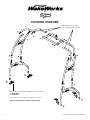
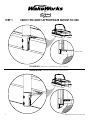
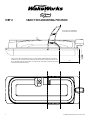
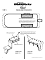
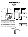
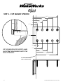
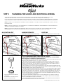
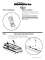
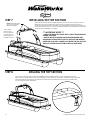
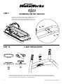
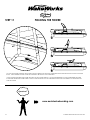
1
by
f250 pontoon WAKEBOARD tower
installation guide
INSTALLATION SUPPORT
1
GUIDE#: PWB-wwpontoon-pol-006
by
important information
• This WakeWorks tower fits Pontoon boats with 96 to 102 inch wide beam widths. This measurement is taken from the Port to Starboard mounting points.
• Do not fold the tower without having the top section securely fastened to the side sections with
the fasteners provided.
• Lubricate the telescopic side section tubes that slide in and out of the top section during installation. We recommend using a light grease to help the tubes slide together without binding.
• Do not fold the tower by yourself.
• Do not assemble tower on the ground and then try to install it on the boat.
• Do not use impact drivers to install any hardware.
• Torque set screws to 35ft-lbs
• Torque shoulder bolts 50 ft-lbs
• Torque tower foot all-thread to 65 ft-lbs
• We recommend using threadlocker on the threads of all fasteners that will not be adjusted
while lowering or raising the tower.
• Check the top section for burrs before installing side sections to prevent the scratching and
marking of tubes. WakeWorks does not cover damage caused by burrs during installation.
• Two types of mounts are provided. One is a top mount and the other is an under mount. Please
select the most appropriate mount for your pontoon boat.
• Please leave the foam wrap on the tower until the installing is complete.
• Please note that when towing your boat you may notice what appears to be movement in
your tower. It is important to understand that the boat is also moving on the trailer and that this
movement can be visually deceiving.
cleaning
• Frequently wash your tower with soap and water.
• As required, use Mothers Mag & Aluminum polish to restore your tower to its original finish.
warning
• BE CAREFUL when assembling this product. We CANNOT be liable for any burring or scratching that may occur when sliding sections in and out of each other.
• NEVER modify this product in any way.
• NEVER climb, stand or ride on this product.
• NEVER tow watersport tubes or inflatable’s with this or any other WakeWorks Wakeboard
Tower.
• ALWAYS use caution with approaching bridges or overpasses.
• ALWAYS inspect this product for loose bolts, fittings or damage before each use.
• Always carefully CONSULT the user manual for proper installation, maintenance and usage.
• WakeWorks is not liable for personal injury or property damage from the use of this or any
other WakeWorks product.
2
GUIDE#: PWB-wwpontoon-pol-006
by
PARTS LIST
Aluminum Under mount
4x
4x
stainless steel top mount
PORT lower SIDE
1x
starboard side
port side
STARBOARD lower side
1x
1x
1x
navigation light
(shipped separately)
front corner
top section
1x
1x
2x
rear corner
2x
3
1/2” - 13 Socket Head cap
(1.375” in length)
16x
1/2” shoulder bolt
(1.25” in length)
4x
GUIDE#: PWB-wwpontoon-pol-006
by
PARTS LIST
0.375”-16 Button
Head Cap
(3” in length)
0.375” flat washer
nylon folding washer
0.375” nylon lock nut
2x
8x
8x
pop up cleat
(shipped separately)
2x
8x
cleat spacer
(shipped separately)
2x
0.19”-24 flat Head Cap
(0.625” in length)
(shipped separately
with pop up cleat)
4x
4
GUIDE#: PWB-wwpontoon-pol-006
by
EXPLODED OVERVIEW
NOTE: lubricate parts with a
light grease before assembly
this tower is supplied with 2 different types of mounts.
1 - under mount
2 - Top mount
select the mount that best fits your pontoon boat.
note: the under mount is shown in this diagram.
5
GUIDE#: PWB-wwpontoon-pol-006
by
step 1
select the most appropriate mount to use.
section view
top mount - designed to fit underneath the play pen rail.
under mount - designed to be installed under the deck.
6
GUIDE#: PWB-wwpontoon-pol-006
by
step 2
select the mounting position
note: do not assemble
the tower at this stage.
using only the lower side section of the tower, determine the mounting
position of each mount and mark this same position on both sides of the
boat. ensure that the mounting locations will provide a square and well
aligned tower installation.
7
XX”
GUIDE#: PWB-wwpontoon-pol-006
by
installing the mounts
step 3
remove the furniture and other items from the location where the mounts will be installed.
important: check the underside of the deck to make
sure that there are no electrical wires, fuel lines,
fuel tanks, or other items that me be damaged while
drilling or screwing the mount into position.
several mounting holes are provided to allow
flexibility with the installation. We recommend
installing the mount with at least 4 bolts (2 per
row). If more bolts can be used then this is also
acceptable.
part a - to be installed on
the top side of the deck.
part B - to be installed on
the underside of the deck.
under mount
designed to be
installed under
the deck.
8
top mount
designed to fit
underneath the
play pen rail.
GUIDE#: PWB-wwpontoon-pol-006
by
step 3 - under mount specific
9.50
8.25
7.00
5.75
4.50
1.38
3.13
4.38
use the dimensions provided to mark and drill
the first hole.
Once the first hole is drilled then ‘Part A’ (the
stainless steel top plate) can be used as a guide
to mark the remaining mounting holes.
5.63
6.88
8.13
when drilling through the boat deck to install
the mount we recommend using a 5/16” drill bit.
it is recommended that red loctite threadlocker
is used when assemblying these fasteners.
this line represents the
edge of the boat deck.
9
GUIDE#: PWB-wwpontoon-pol-006
by
step 3 - top mount specific
5.875
4.675
3.475
2.275
1.075
.786
.289
1.489
use the dimensions provided to mark
and screw the mounting plate to the
deck of the boat.
2.689
3.889
5.089
this line represents the
edge of the boat deck.
10
GUIDE#: PWB-wwpontoon-pol-006
by
step 4
install the lower side sections
install each lower side section using the bolts provided.
it is recommended that you use red loctite threadlocker
while assembling these fasteners.
top mount
11
under mount
GUIDE#: PWB-wwpontoon-pol-006
by
step 5
planning for audio and electrical wiring
AT THIS STAGE IT IS IMPORTANT TO PLAN FOR AUDIO AND ELECTRICAL ACCESSORIES THAT WILL BE MOUNTED TO THE TOWER.
WE RECOMMEND INSTALLING THE NAVIGATION LIGHT WHICH IS SUPPLIED WITH THE TOWER (SHIPPED SEPARATELY).
IF YOU ALSO PLAN ON INSTALLING SPEAKERS OR LIGHTS THEN NOW IS THE TIME TO RUN THE WIRES FOR THESE ADDITIONAL ACCESSORIES.
THE DIAGRAMS BELOW SHOW SOME TYPICAL ACCESSORY MOUNTING LOCATIONS AND THE RECOMMENDED WIRING PATH FOR EACH.
NOTE: THE WIRING OF ACCESSORIES MAY REQUIRE TECHNICAL EXPERTISE. IF YOU ARE IN ANYWAY UNSURE PLEASE CONTACT AN INSTALLATION SPECIALIST.
NOTE: ACCESSORY POSITIONS MAY VARY DEPENDING ON YOUR PERSONAL PREFERENCE AND REQUIREMENTS. THE DIAGRAMS BELOW
ARE SIMPLY SUGGESTED MOUNTING LOCATIONS.
NOTE: THE TOWER IS NOT SUPPLIED WITH PRE-DRILLED WIRING HOLES AS EACH CUSTOMER MAY HAVE A DIFFERENT WIRING REQUIREMENT DEPENDING ON HOW THEY FOLD THEIR TOWER OR THE ACCESSORIES THAT THEY WILL MOUNT TO THE TOWER.
NAVIGATION LIGHT
(MOUNT TO TOP OF TOW POINT)
WIRES MUST EXIT
AROUND THE
FOLDING FITTINGS
HANGING SPEAKERS
(MOUNTED TO THE REAR TOP SECTION TUBE)
WIRES MUST EXIT
AROUND THE
FOLDING FITTINGS
LIGHT BAR
(MOUNTED TO THE FRONT TOP SECTION TUBE)
WIRES MUST EXIT
AROUND THE
FOLDING FITTINGS
TIPS FOR RUNNING WIRES THROUGH THE TOWER
THE NAVIGATION LIGHT IS SHIPPED
SEPARATELY.
IT IS DESIGNED TO BE INSTALLED ON
THE TOP OF THE TOW POINT.
12
RUNNING WIRES CAN SOMETIMES BE A TRICKY JOB BUT WITH THE HELP OF A VACUUM CLEANER,
STRING AND TAPE IT CAN MAKE THE JOB REASONABLY EASY.
- CUT YOURSELF 4 TO 5 LENGTHS OF STRING THAT WILL BE LONG ENOUGH TO PASS THROUGH EACH
SECTION OF THE TOWER (ROUGHLY 4’ TO 5’ EACH - IN LENGTH).
- USING THE SUCTION OF A VACUUM CLEANER, RUN ONE LENGTH OF STRING THROUGH EACH
SECTION OF THE TOWER, ENTERING AND EXITING IN THE LOCATIONS THAT BEST SUIT YOUR APPLICATION. NOTE: WITH TAPE, YOU MAY NEED TO COVER OPEN HOLES IN THE TOWER SECTIONS TO
INCREASE THE SUCTION STRENGTH THROUGH THE WIRING PATH.
- ALSO NOTE THAT IF YOU PLAN TO FOLD THE TOWER YOU WILL NEED TO EXIT AND ENTER AROUND
THE FOLDING FITTINGS. YOU MAY NEED TO DRILL EXIT AND ENTRY HOLES AS REQUIRED. NOTE: MAKE
SURE THESE WIRING HOLES ARE NO LARGER THAN A 1/2”.
- ONCE EACH SECTION HAS THE STRING RUN THROUGH IT YOU WILL THEN BE ABLE TO BEGIN ASSEMBLY OF THE TOWER. NOTE: AS EACH SECTION IS JOINED TOGETHER, THE STRING AT THESE JOINING
POINTS WILL ALSO NEED TO BE CONNECTED. SECURE KNOTS WILL BE REQUIRED SO THAT THE CONNECTION POINTS DON’T PULL LOOSE AS YOU ARE PULLING THE WIRE THROUGH THE TOWER. WE
ALSO RECOMMEND TAPING OVER THESE KNOTS SO THAT THEY ARE STREAMLINED AND DON’T GET
CAUGHT ON THE ENTRY AND EXIT POINTS.
- FOLLOWING THE ASSEMBLY INSTRUCTIONS YOU WILL THEN BE ABLE TO CONNECT THE END OF
THE WIRES TO THE END OF THE STRING AND SLOWLY AND CAREFULLY FEED AND PULL THE WIRES
THOUGH THE DIFFERENT SECTIONS OF THE TOWER.
- ONCE THE WIRES REACH THE BOTTOM OF THE TOWER THEY CAN THEN BE TUCKED IN UNDER THE
DECK OF THE PONTOON BOAT FOR A NICE CLEAN LOOK.
GUIDE#: PWB-wwpontoon-pol-006
by
wires & fittings
step 5 CONTINUED...
you will notice that all of the fittings have wiring
holes drilled in them. these wiring holes allow the
wires to run right through the tower and remain
completely hidden.
note: If you will be folding your tower from time
to time it is recommended that you consider the
wiring path so that it can allow for the tower to
fold. In some cases the wires may need to exit and
enter the tubes around the fittings or even include
wiring connectors.
step 6
installing the side sections
instal each side section using the shoulder bolts provided.
the nylon washers should be placed between the fittings in the
front joints. this will create space between the aluminum parts
to allow the tower to fold.
A
13
GUIDE#: PWB-wwpontoon-pol-006
by
step 7
installing the top section
Insert the front and rear corner tubes into the top section. be careful not to
insert them too far as the sliding motion may cause the tubes to scratch.
once the parts are loosely together, the corner tubes can then be attached to
the side sections with the 1/2” bolts provided. During this process try to keep the
top section as centered as possible.
NOTE: lubricate parts
with a light grease
before assembly
**pull wires
through top
section before
connecting to
wiring string in
the side section.**
*** IMPORTANT NOTES ***
- LUBRICATE TELESCOPIC PARTS WITH A LIGHT GREASE BEFORE
SLIDING TOGETHER.
- GREASE WILL NOT PREVENT THE SMALLER DIAMETER TUBE
FROM BEING SCRATCHED BY THE TOP SECTION TUBE DURING
INSERTION SO BE VERY CAREFUL NOT INSERT THE SIDE SECTION
TUBE ANY FURTHER THAN THE FINAL INSTALLATION WIDTH.
drilling the top section
step 8
once the top section is in place and centered on the tower and boat, it will then be time to drill
through the corner tubes so that the fasteners can be installed to securely fasten the parts together.
use the pre-drilled holes in the top section as the template for drilling through the corner tubes.
a 27/64” drill bit is recommended.
A
14
GUIDE#: PWB-wwpontoon-pol-006
by
step 9
fastening the top section
install the 0.375” button head bolts, washers and nuts to
secure the top section and corner tubes in place.
we recomend using red loctite threadlocker on the
nuts and bolts when assembling these components.
K
step 10
cleat installation
lift and rotate the top section of the cleat to allow the fasteners to pass through the installation
holes. Install the cleat on top of the cleat spacer using the fasteners provided. we recommend using
red loctite threadlocker when installing these fasteners.
15
GUIDE#: PWB-wwpontoon-pol-006
by
folding the tower
step 11
to fold the tower forward, disconnect the two rear legs from the lower side sections by removing the two shoulder
bolts. Once these bolts are loose the tower will be able to fold forwards.
Once folded forwards the tower will rest on the playpen railing. We suggest inserting a soft pad between the parts
in the area where the tower makes contact with the boat so that it prevents scratching or marking of both the boat
and the tower.
Questions?
www.aerialwakeboarding.com
16
GUIDE#: PWB-wwpontoon-pol-006