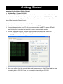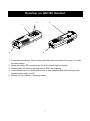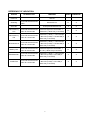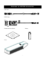
1
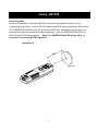
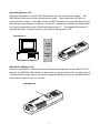
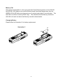
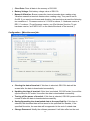
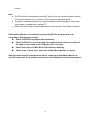
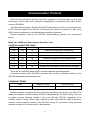
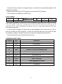
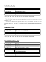
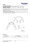
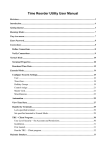
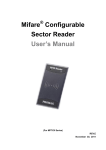
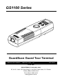
GS1100 Series GuardScan Guard Tour Terminal Manual Part Number : TM951199 REV : 02 Dev 2009 GIGA-TMS REGISTERED TO ISO 9001:2000 8F, No.31, Lane 169, Kang-Ning St., Hsi-Chih Taipei Hsien, 221 Taiwan Phone: (886) 2-2695-4214 FAX: (886) 2-2695-4213 www.gigatms.com.tw GIGA-TMS INC. Printed in Taiwan Information in this document is subject to change without notice. No part of this document may be reproduced or transmitted in any form or by any means, electronic or mechanical, for any purpose, without the express written permission of GIGA-TMS Inc. REVISIONS Rev Number Date Note 01 Oct 2007 Initial Release 02 Dev 2009 Update GuardScan Monitor 2 Getting Started Important Notice before Getting Started: Update Date / Time of GS1100 For each new GS1100 terminal, the internal date / time value needs to be calibrated with your local time for the first time. After synchronizing the date / time of GS1100 with your PC (refer to point a. on page 12), please follow the steps as below to make sure if the date / time of the terminal is correct or not: 1. Do not need to connect the terminal with PC now. 2. Press the scan button of the terminal to read several RFID tags. 3. Connect the terminal to your PC with the communication cable. The green LED will keep blinking that indicates the terminal is under communication mode. 4. Launch GuardScan Monitor program. On [General Commands] tab, select the connected COM port. Click [Download Data] to download all data from the terminal to your PC. The screen shot will appear as below: 5. View the data records and make sure if the date / time of each record is correct or not. 6. Once you confirm that the collected data and time are correct, click [Clear Data] to clear the testing data in GS1100. Now you are ready to start with your GS1100. 3 Introduction The new GS1100 GuardScan Plus is a more convenient Guard Tour Data Collection Terminal, based on RFID technology, it helps you watch over your employees that have had difficulties to track those whose working duties require moving from place to place, such as security guard patrolling, policeman patrolling, remote equipment inspection / maintenance...etc. The friendly design of vibration feedback keeps your reading work to be more focus and completed. The situation of lack of battery power will not happen to you any more because of the vibration design feedback which will not work when battery power is low. Use our application software "Patrol Manager" (optional) you may set up a remarkable Patrol Management System. Table Contents 1. Overview on GS1100 Handset 2. 3. 4. 5. 6. 7. 8. ……………………….…………………..………….…5 Overview on GS1100 Accessories ………………………………………………….….7 Using GS1100 …………………………………………………………..………………..8 GuardScan Monitor Program ……………………………………………………….....11 Communication Protocol ………………………………...…………………………..…15 Firmware Management Mode ………………………..……………………..……..…..21 Hardware Test ………………………………………..…………………………………..23 GS1100 Specification ………………………………………………………………..….24 4 Overview on GS1100 Handset 2 5 1 4 3 1. Power/Scanning button: continuously press this button and switch the power on to start 2. 3. 4. 5. the data reading. Status indicating LED: served as the GS1100 handset status indication Sensing field: the effective working area of RFID Tag scanning Communication port: to complete the work of data uploading and downloading via the communication cable to a PC. Battery Lid: the position of changing battery. 5 REFERENCE OF INDICATION: STATUS SCAN BUTTON LED/BEEP SCAN VIBRATION LED off X X SCAN LED on O X A beep and SCAN LED off X O Power off Scanning Press and hold the SCAN button Scan OK Flash Memory Low Press and hold the SCAN button for 20 seconds SCAN LED lights for 10 seconds -> SCAN LED (1 blink every 2 seconds) O X Flash Memory Full Press and hold the SCAN button for 10 seconds SCAN LED (1 blink) -> 3 short beeps -> B/L LED (1 blink) -> SCAN LED (2 blinks every 2 seconds) X X RTC Abnormal Press and hold the SCAN button for 10 seconds SCAN LED (1 blink) -> 3 short beeps -> B/L LED (1 blink) -> SCAN LED (3 blinks every 2 seconds) X X Battery Low Press and hold the SCAN button for 20 seconds SCAN LED lights for 10 seconds -> B/L LED (1 blink every 2 seconds) O X EEPROM Fail Press and hold the SCAN button for 10 seconds SCAN LED (1 blink) -> 3 short beeps -> B/L LED (1 blink) -> B/L LED (2 blinks every 2 seconds) X X FLASH Fail Press and hold the SCAN button for 10 seconds SCAN LED (1 blink) -> 3 short beeps -> B/L LED (1 blink) -> B/L LED (3 blinks every 2 seconds) X X 6 Overview on GS1100 Accessories USB Cable : CABLE P/N : WAS-XXXX REV.X RS232 Cable : Software and User Manual Battery Cover 7 Using GS1100 Recording Data Shown as illustration 2, hold the GS1100 in the scanning distance at about 60 mm ( depending on the tags ), aim the GS1100 head at the RFID tag and press the Scan button till the GREEN SCAN LED turns ON to read the RFID tag . Meanwhile you will hear one beep which means a successful reading is achieved , then the GREEN SCAN LED will turns off and GS1100 body shakes . Note: The GREEN SCAN LED will go off in 10 seconds if the scanning RFID tag failed . illustration 2 RFID Tag 8 Uploading Data to a PC Shown as illustration 3, connect GS1100 terminal with the communication cable. The GS1100 itself will enter into the communication mode. Note: When the GS1100 is in communication mode, it is not able to scan the RFID tag even if you press the Scan button. We strongly recommend you to do the “ Power Off” command to conserve the battery after you have completed the work of Data Uploading to the PC. The handset will switch off automatically after 3 minutes once it is not communicating with the PC . illustration 3 USB PORT or RS232 PORT Personal Computer Indication of Battery Low Shown as illustration 4, when you press the Power/Scanning button on the GS1100 for 10 seconds, the RED B/L LED will start to flash once at every 2 seconds then the light goes off 10 seconds later which means you should change the battery as soon as possible because the handset is about to run out of power. illustration 4 9 Memory Full Also shown as illustration 4, when you press the Power/Scanning button on the GS1100, the RED B/L LED flashes once and the Buzzer keeps three beep-beep-beep; then the GREEN SCAN LED blinks two times at every 2 seconds and stops 10 seconds later. The GS1100 is not able to read any RFID Tags. This indicates that the Memory inside the GS1100 is full and the data in the Memory should be downloaded. Changing Battery Please follow the illustration 5 for battery replacement. illustration 5 - - + 10 GuardScan Monitor Program System Requirements: 1. Operating System: Windows 98/ME/2000/XP, Vista 32/64 and Windows 7 32/64. 2. IE web browser V4.0 or above is required. Program Setup: 1. Place Setup CD into CD-ROM Drive. 2. A setup wizard will pop up. Follow the instructions to complete the program setup. (If CD-ROM auto-run function is disabled, double-click the setup.exe manually for the program installation.) Launch Program: 1. From [Start] / [Programs] / [GIGA-TMS], click [GuardScan Monitor]. 2. A [Password Required] window will pop up, enter correct password (default is 0000), and then go to GuardScan Monitor program main window. Hardware Connection: 1. Connect the terminal to COM port (or USB port) of your PC with the communication cable. The green LED will keep blinking that indicates the terminal is under communication mode. 2. If you don‟t know the COM port number applied to USB port, go to Window\Control Panel\System\Hardware\Device Manager\Ports (COM & LPT) to see. 11 Configuration - [General Commands] tab: Set [Comm. Port] that the terminal is connected. Each command result will show in the Message box. a. Set Time: Update the specified date / time to GS1100. b. Sync. Time: Synchronize date / time of PC to GS1100. c. Set Mach#: Update the specified machine number to GS1100. The value of machine number must be in the range of 0 ~ 255. (Remark: Please delete all data stored in GS1100 terminal before starting to set up machine ID and date / time.) d. Get Time: Get GS1100‟s time value and show in the Message box. e. Get Mach#: Get GS1100‟s machine number and show in the Message box. f. Get Version: Get GS1100‟s firmware version and show in the Message box. g. Power Down: Turn off the GS1100. h. Record Count: Get the total number of scanned tag(s) and show the number in the Message box. i. Download Data: Transfer the scanned tag(s) data from GS1100 to PC. The data will be saved as a text file, and the filename can be specified under [Miscellaneous] tab. The downloaded data will show in Message box. The fields of the record define as below: [Machine No#], [Tag Code], [Date (year/month/day)], [Time (hour/minute/second)] 12 j. Clear Data: Clear all data in the memory of GS1100. k. Battery Voltage: Get battery voltage value of GS1100. l. Buzzer & Vibration: Buzzer means the terminal sounds when reading a tag. Vibration means the terminal vibrates when reading a tag. They can be set to On/Off. If you want to set buzzer and vibration, the terminal must meet the following two conditions: 1. Firmware version is V1.01R0 or above; 2. Hardware version is REV. C or above. (To get firmware version, use [Get Version] function. To get hardware version, see “MFG. NO” on the label at the back of the terminal.) Configuration - [Miscellaneous] tab: a. Clearing the data of terminal: If this item is selected, GS1100‟s data will be erased after the data is downloaded successfully. b. Updating the time of terminal: If this item is selected, GS1100‟s date / time will be synchronized to PC‟s date / time after the data is downloaded successfully. c. Turning off the power of terminal: If this item is selected, GS1100‟s power will be turned off after the data is downloaded successfully. d. Saving/Appending the downloaded data to the specified file: If this item is selected, the download data will be saved to the specified file. Besides, if the specified file exists, the new data will be appended in the end of existed data. e. Change Password: Modify the software password. It will take effect on the next 13 launch. Note: a. GS1100 will be automatically turned off if there is not any communication between PC and the terminal over 3 minutes. This is for power saving purpose. b. To prevent unwanted people from using GuardScan Monitor program, make sure the program is ended when leaving PC. c. Make sure all the data is downloaded before executing the Clear Data command. If GuardScan Monitor cannot work properly with GS1100, please check it up according to following procedures: Check if GS1100 is equipped with the battery. Check if GS1100 is connected with the communication cable correctly and the cable is connected to the COM port of PC correctly. Check if the Green SCAN LED of GS1100 keeps blinking. Check if the “Comm. Port” selection in GuardScan Monitor is correct. After you have done all procedures as above, restart your GuardScan Monitor to check if it runs well. If not, please contact your local distributor for technical support. 14 Communication Protocol GS1100 communications protocol has been extended to accommodate several new commands. At the same time, backward compatibility is maintained with earlier device version (GS1000A). Communications between the GS1100 and PC take place in the form of commands sent by PC side and replies from GS1100. Commands and replies are packets of data using ASCII control characters to mark beginning and ending of packets. Control characters used by the GS1100 communications protocol are summarized below: Baud rate: 19200 bps, None parity,8 data bits,1 stop, CONTROL CHARACTER TABLE ITEM Hex Control Key Function STX 02H ^B Marks the beginning of data packet ETX 03H ^C Marks the ending of data packet EOT 04H ^D Indicates the end of data exchange ENQ 05H ^E Marks the beginning of command packet ACK 06H ^F Acknowledges reception of data NAK 15H ^U Requests data retransmission ETB 17H ^W Signals that command or data was not accepted There are two different packet types: command packets and data packets. Command packets start with ENQ character and contain a machine number of the GS1100 addressed and command code. COMMAND FORMAT ENQ machine number command code 1 character 2 characters 1 character Machine number is supplied as a two-character Hex string and can be in the 00H...FFH range (for example, machine number of 4AH is represented by „4A‟ ASCII string). 00H is a so-called universal machine number, it will work with any GS1100, regardless of its machine number setting. When using machine number other than 00, make sure that it matches current machine number of the GS1100 (set by “P” command). Using universal machine number of 00 will work well in all situations. 15 Command code consists of a single character. See below for complete description of all available commands. Data packets start with the STX character and end with ETX character. ETX character is followed by the BCC byte. DATA FORMAT STX 1 ch. Data characters ETX BCC 1 ch. 1 ch. BCC byte is a result of consecutive XOR operations on all data packet bytes excluding STX, ETX and BCC byte itself. It is important to realize that BCC byte can contain any value from 00H to FFH . When designing PC software, be sure to distinguish between BCC byte and control characters. In many cases, reception of data must be acknowledged by the receiving side. This is done by sending the ACK character. In case the receiving side does not accept the data (for whatever reason), the NAK character may be sent to request retransmission. Summarized below are all supported commands: COMMAND INDEX TABLE Command ASCII Description „S‟ 53H Set date/time „T‟ 54H Get date/time „I‟ 49H Download log database data „D‟ 44H Initialize (clear) log database „M‟ 4DH Prepare to recover log database data „A‟ 41H Get total number of records in log database „P‟ 50H Set Machine ID „Q‟ 51H Get Machine ID „V‟ 56H Get firmware version „Z‟ 5AH Invoke Test mode „O‟ 4FH Power down (go into Sleep) „F‟ 46H Login EEPROM Test Mode „X‟ 58H ISP Mode 16 Set Date/Time („S‟, 53H) PC to GS1100 ENQ-M#-„S‟ GS1100 to PC ACK* PC to GS1100 STX-date/time-ETX-BCC GS1100 to PC ACK/(NAK)** PC to GS1100 EOT Date/time field has the following format: YYYYMMDDhhmmss, where: YYYY- year, MM- month, DD- date, hh- hour, mm- minutes, ss- seconds. *The GS1100 will accept this command regardless of whether there is any data in the log database or not. **The GS1100 will accept any date/time data, even if it is invalid (for example, even with the month set to 13). Use new “T” command to verify if new date and time were actually set. Get date/time („T‟, 54H) PC to GS1100 ENQ-M#-„T‟ GS1100 to PC STX- date/time field*- ETX-BCC PC to GS1100 ACK/(NAK) GS1100 to PC EOT Date/time field has the following format: YYYYMMDDhhmmss, where: YYYY- year, MM- month, DD- date, hh- hour, mm- minutes, ss- seconds. Download database data („I‟, 49H) PC to GS1100 ENQ-M#-„I‟ GS1100 to PC STX- first record data- ETX-BCC PC to GS1100 ACK/(NAK) GS1100 to PC STX- next record data- ETX-BCC PC to GS1100 ACK/(NAK) More records… …and acknowledgements GS1100 to PC STX- last record data- ETX-BCC PC to GS1100 ACK/(NAK) GS1100 to PC EOT 17 Record data format: MM,II…I,YYYY/MM/DD,hh:mm:ss, where MM- machine number, II…I- RFID tag‟s ID-code, YYYY- year, MM- month, DD-date, hhhour, mm- minutes, ss- seconds. Initialize (clear) database („D‟, 44H) PC to GS1100 ENQ-M#-„D‟ GS1100 to PC ACK* PC to GS1100 EOT This command reinitializes the log database. All contents are logically deleted, which means that actual record data is not erased, just some database-related housekeeping is initialized. The log database data can still be recovered (if not already written over) using “M” command. Prepare to recover database data („M‟, 4DH) PC to GS1100 ENQ-M#-„M‟ GS1100 to PC ACK PC to GS1100 EOT This command alters log database in such a way that it appears to be 100% full. Subsequent “I” command will download the contents of entire log database memory. This command, therefore, can be used for data recovery purposes. Get total number of records in the database („A‟, 41H) PC to GS1100 ENQ-M#-„A‟ GS1100 to PC STX-number of records-ETX-BCC PC to GS1100 ACK/(NAK) GS1100 to PC EOT Number of records in the log database is returned as a 6-digit decimal string. Leading zeroes are appended to keep the string size constant. Set machine number („P‟, 50H) PC to GS1100 ENQ-M#-„P‟ GS1100 to PC ACK PC to GS1100 STX-new machine number-ETX-BCC GS1100 to PC ACK* PC to GS1100 EOT 18 New machine number is a 2-byte Hex string. Therefore, machine number can have a value in the 00H…FFH range. Get machine number („Q‟, 51H) PC to GS1100 ENQ-M#-„Q‟ GS1100 to PC STX-current machine number-ETX-BCC PC to GS1100 ACK/(NAK) GS1100 to PC EOT Current machine number is a 2-byte Hex string. Therefore, machine number returned can be in the 00H…FFH range. Get firmware version („V‟, 56H) PC to GS1100 ENQ-M#-„V‟ GS1100 to PC STX-version string-ETX-BCC PC to GS1100 ACK/(NAK) GS1100 to PC EOT Version string can have a variable length but will never exceed 61 character. Although it is technically possible to have a version string with any kind of ASCII data in it, we commit to the following format: Vx.xx pp…p nn…n, where Vx.xx- version number (i.e. “V1.25”), pp…p- product model number (i.e. “GS1100”), nn…n- note (i.e. “rev. 01/01/2000”). Version number, product model number and note fields are separated by space characters. Version number and product model number are guaranteed to contain no space characters. Note field can contain any characters including spaces. Invoke Test mode („Z‟, 5AH) PC to GS1100 ENQ-M#-„Z‟ GS1100 to PC !!! No reply from GS1100 !!! This command is used to force the GS1100 into a special Test mode. No reply is issued by the GS1100 upon receiving this command. Details of GS1100 operation in the Test mode are provided in Hardware Testing. Note that Test mode destroys log database memory contents in such a way that the data cannot be recovered even with the “M” command. 19 Power down („O‟, 4FH) PC to GS1100 ENQ-M#-„O‟ GS1100 to PC ACK This command puts the GS1100 into the low-power sleep mode. Following this command all communications are suspended. The User must press the Scan button to reawaken the device. Login EEPROM Test Mode („F‟, 46H) PC to GS1100 ENQ-M#-„F‟ GS1100 to PC ACK It is used to reset initial value of GS1100 for the manufacture. Not Recommended for user‟s software. Go to ISP Mode („X‟, 58H) PC to GS1100 ENQ-M#-„X‟ GS1100 to PC ACK This command puts the GS1100 into the Firmware Management Mode (FMM) . FMM allows you to quickly upgrade your GS1100‟s internal firmware and also check validity of currently loaded firmware. Contact your dealer for most recent firmware upgrade files. 20 Firmware Management Mode GS1100 features the Firmware update function in quick and easy way to access. Please refer to following instructions : 1. Check it up with your local distributor for the latest version ROM-T0836 Connect GS1100 to PC comm. Port. Press the “Power/Scanning” button for 1 second to make GS1100 enter into communication mode. 2. Being using your “Rom Manager” software by selecting GS1100 connection to PC communication port. 3. Click “ Update” button and select the path “ ROM-T0836” and press “ Yes” to access the updating 21 4. The complete of firmware updating window reads as follows Note: Once you found the firmware is not working well which may indicate that you are not able to follow above procedure to complete the firmware updating. By avoiding this, you may connect USB cable into PC comm. port or USB port, connect communication cable into GS1100 communication port and press the Scan button till the RED B/L LED lights up. Now GS1100 is in the mode of ISP; you may follow the procedure from 3 to 4 to continue the updating. 22 Hardware Test An additional feature of GS1100 is the ability to do the Hardware test. Please refer to “Communication section” to start. Command “ Z” is the said command. ( Also refer to page 17 command) Two steps are covered in the work of Hardware testing Flash memory testing When you are accessing the flash memory test, the GREEN SCAN LED will keep blinking in quick motion. Once the work is done one beep will sound and the GREEN SCAN LED/RED B/L LED will change to blink normally to indicate the completion of testing. If the Flash memory test runs in failure, you will hear two beeps and the RED B/L LED lights up. Be sure you have to restart the second times testing in 10 seconds or the Program may tell it is a failure testing. Same as the previous condition, two beeps will sound and the RED B/L LED will light up. GS1100 Handset with RFID tags reading test Then we go for the 2nd step. At this point you will see the GREEN SCAN LED and RED B/L LED are in cross flashing when you hold up the GS1100 handset. Following you need to scan the RFID tags for data reading with 5 times to make sure the hardware is functional. Every record of data reading, a beep sound can be heard. Once the successful testing is complete, GS1100 handset will go a long beep and the GREEN SCAN LED flashes at the same time. The terminal will automatically shut down after 5 seconds. If the RFID Tags data reading test does not access successfully, two beeps will run and the RED B/L LED lights up; the terminal automatically shuts down after 5 seconds. Note: the hardware self- test will make GS1100 go back to initial value set up. The records inside the flash memory are deleted forever which means retrieval is not possible with the command “M”. 23 GS1100 Specification Storage Capacity: 14320 RFID card format: 125KHz, ASK, 64 Bits Manchester Coding Reading distance: around 60~70 mm depending on the tags Operating time in active (scanning) mode: up to 50,000 reading ((brand new Duracell MN1500, LR6, DC 1.5V battery, on line 1 second, off line 1 second covering the time of data uploading to PC) Battery specification: DC 1.5 volt, No. 3 battery (brand new Duracell MN1500, LR6, DC1.5V battery) Communication interface: RS232 (GS1100) USB (GS1100U) Protocol: 19200bps, 8 N 1 Physical dimension: L 165 mm * W 48mm * H 34 mm Weight: 120 grams (without battery) Certificate: CE , FCC EN 55022 Class A EN 61000-3-2 Class A EN 61000-3-3 Class A EN 55024 Class A EN61000-4-2 Class A EN61000-4-3 Class A EN61000-4-4 Class A EN61000-4-5 Class B EN61000-4-6 Class A EN61000-4-8 Class A EN61000-4-11 Class A Operation temperature: - 10 - + 50℃ Storage temperature: -20~+60℃ Operation humidity: 5-95% 24