1
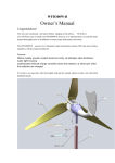
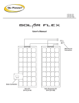
FD2.5-300
Owner’s Manual
Congratulations!
You have just purchased an advanced battery charging wind turbine.
We believe you will find it
easy to install your FD2.5-300; however, it is important that you read this entire manual
thoroughly prior to installation to assure proper performance and safety.
The FD2.5-300 consists of a 12.5 kilogram weight wind turbine rated at 300 watts with a built-in
regulator, and self-governing mechanisms.
If you have any questions after thoroughly reading the manual, please contact your authorized
distributor/dealer.
Specifications
Model: FD2.5-300
Rated Power: 300W
Maximum Power: 500W
Rotor Diameter: 1.5m
Start-up Wind Speed: 2.5m/s
Rated Wind Speed: 12m/s
Rated Voltage:
12V or 24V
Net Weight: 17kg
It can supply about 50kwh per month under the condition: average wind speed is 12m/s per day,
valid wind hours is 210h per month
Power Curve
1. Safety Precautions
When installing the FD2.5-300, exercise due care at all times. The turbine weighs 12 kilograms
and is awkward in shape. It is best to plan the installation carefully in advance and enlist some
help when erecting the machine in order to avoid accidents.
NOTE: Complete as much of the installation procedure as possible at ground level.
Choose a calm, dry day for your installation if possible.
FD2.5-300 blades are quite sharp, particularly on their trailing edges. Handle with care.
FD2.5-300 is robustly engineered, but contains high-energy permanent magnets that can be
damaged if the machine is dropped or handled heavily. Please handle with care.
When running, particularly if disconnected from the batteries, FD2.5-300 is capable of producing
high voltages. Caution must be exercised at all times to avoid electric shocks.
Always observe correct polarity when connecting FD2.5-300 to an electrical circuit.
polarity connection will result in damage to the wind generator.
Reverse
The FD2.5-300 must be appropriately fused at all times.
WARNING: Never approach the path of the blades when the machine is operating as severe
personal injury could result.
WARNING: Always stop the machine and secure the blades before attempting maintenance.
WARNING: Ensure that all batteries are disconnected when undertaking maintenance.
2.
Package Contents
Compare the parts shown in Figure 1 to ensure that the contents of the box contain all
necessary parts.
Name and Quantity of Each Components
1 – Generator, tail and flange assembly
2 - Blades
3 - Flange for blades
4, 5, 6 – Bolts, Nuts and Washer
7 - Dome
8 - Screw
9, 10, 11 - Bolts, Nuts and Washer
12 - Screw
13 – Rubber Cover (no displaying)
1 set
3 pc
1 pc
9 sets
1 pc
1 pc
1 set
4 pc
1 pc
3. Wiring
System Wiring Diagrams
We recommend you wire the turbine directly to the battery bank to its own set of battery posts.
This internal regulator will independently monitor the battery and charge as necessary
Electrical Connections
CAUTION: MAKE SURE THE TURBINE IS DISCONNECTED
FROM THE BATTERIES DURING INSTALLATION.
Avoid connecting different metals together(i.e., copper and aluminum). This will cause a
galvanic cell that will erode one of the metals.
When such connections can not be avoided,
consult your dealer or an electrical supply house for anti-oxidant compounds. If possible solder
wire termination ends.
CAUTION: CONNECTIONS SHOULD BE INSPECTED
PERIODICALLY FOR SIGNS OF CORROSION AND
CLEANED WHEN NECESSARY
NOTE:
All electrical power cables should be physically protected.
tower or conduit for maximum protection.
NOTE:
Run the wires inside the
The yaw can support a total of 70 kg in wire weight. For higher wire weights, you
must install a strain relief to minimize the stress put on the hanging wires.
Fusing
The FD2.5-300LH is capable of producing high amperages. As with all electrical installations,
you must protect each of your turbines with a properly sized fuse or circuit breaker.
The
FD2.5-300LH should be wired with an appropriately sized “slow-blow” type fuse between itself
and the batteries.
Recommended Size for Circuit Breakers or Slow-Blow Fuse
12-volt model : 100 amps D.C.
24-volt model : 50 amps D.C.
4. Mounting To Tower
4.1
Hub and Rotor Assembly
Mounting the Blades. Please see the pictures below.
Tighten all the screw with wrench to 10-12 foot lbs(13.6-16.3 Nm)
4.2
Mounting the Hub and Rotor
Carefully slide the blade assembly onto the alternator shaft. Place the washers and
Nut on the shaft. Tighten the nut to 50-65 foot pounds(68-88 Nm). See pictures below.
4.3
Attaching Nose Cone
Carefully place the nose cone over the hub and the blades.
Insert the screw and tighten. See pictures.
Snap the nose cone into place.
5. Attaching to Pole
5.1
Blade-to-Tower Clearance
Make sure that your tower allows for proper clearance of the blades. A minimum 100 mm
clearance must be given between the blade tips and any obstruction. Refer to Figure below
The FD2.5-300 is designed to be mounted on a 1 1/2” steel pipe.
5.2
Step by Step Instructions
1) Run the wires from the battery(do not connect to the battery), through the pole to the top of
the tower. Be sure not to connect the wires to the battery until everything else has been
completed.
2) Strip the insulation back from each set of wires.
3) Mark both ends of all the wires with tape to identify which is positive, negative and earth
ground.
4) Insulate the connections using either heat shrink tubing or a quality electrical tape.
5) Connect the wires from the FD2.5-300 to the wires running to the battery.
6) Once the wires are attached to the FD2.5-300, gently pull the wires down through the tower
sliding the yaw shaft over the 1 1/2” steel pipe.
7) Slide the yew shaft all the way down over the end of pole being careful not to pinch the yaw
wires. Be sure to leave enough slack in the wires so that if necessary, the turbine can be
removed.
8) Once the yaw shaft is on the tower, firmly tighten the yaw clamp screw.
9) Check your FD2.5-300 to be sure that it is securely attached to the mounts. Remember that
this attachment will have to hold in high winds.
10) Run all wires from the turbine to the battery.
11) Before attaching the wiring to the battery, make sure that all circuit breakers are in the off
position.
12) Attach wires to the battery. Positive wire to positive, negative to negative.
13) Turn on the circuit breakers
14) You have now completed the installation process.
6.
Testing
6.1 Alternator
The FD2.5-300 uses a three-phase brushless permanent magnet alternator internally rectifies the
power to D.C. The rotor is comprised of Neodymium Iron Boron arched magnets, the most
powerful magnet material available. The stator is hand wound for maximum output.
6.2 Regulator
When the battery voltage matches the regulation set point the turbine will “shut off”. Normal
charging will resume when the battery voltage drops slightly below the fully charged level. For
12V turbines the turbine will resume charging at 12.6V(25.2V for 24V turbines, 37.8V for 36V
turbine and 50.4V for 48V turbine)
Note:
Bad
connections, undersized wires, and inline diodes will cause the internal
regulator to not work properly.
6.3 Bench Testing
Two quick bench tests can verify if your FD2.5-300 is providing output.
Test 1
1. Remove blade assembly from turbine and place in a safe location.
2. Spin rotor shaft with your fingers while at the same time connecting and disconnecting the
positive and negative yaw wires.
3. With the yaw wires connected, the rotor shaft should become more difficult to rotate and feel
“lumpy”.
With the yaw wires disconnected it should spin freely. If these conditions do not
exist, you should contact your turbine dealer.
6.4
Performance Test
Electrical System.
Your battery bank should be a minimum 400 amp hours for 12 V systems,
and 200 amp hours for 24V system and 36V system.
If your battery bank is smaller than the
recommended size, battery voltage could quickly rise while the turbine is charging and cause the
internal regulator to prematurely stop charging.
Measure the voltage at the battery terminals to which the FD2.5-300 is connected. For the
factory regulation set point, if the voltage for a 12V system reads 14.1V or higher(24V 28.2;
36V 42.3; 48V 56.4), then the turbine will sense the battery is charged and stop producing
power.
NOTE: THE FD2.5-300 ELECTRONICS INCLUDING INTERNAL DIODES.
DO NOT PUT ADDITIONAL BLOCKING DIODES BWTWEEN THE
FD2.5-300 AND THE BATTERIES.
ANY DIODES BETWEEN THE
FD2.5-300 AND THE BATTERIES WILL PREVENT THE TURBINE FROM
PROPERLY “SENSING” THE BATTERIES.
7. Maintenance
Do the following check every three months.
7.1
7.2
7.3
7.4
Check blades for chips or nicks. Replace blades if necessary.
Do not operate the turbine
with chipped or unbalanced blades. This can cause severe wear, damage, and possible
failure.
Check the blade bolts and hub nut.
Inspect the tower.
Check all electrical connections to make sure they are tight and free from corrosion
8. Frequent asked questions
Q: Can I disconnect my FD2.5-300 without damaging it?
A: You can disconnect it without causing any damage.
Q: Is it possible to short my FD2.5-300?
A: Yes, you can short it without causing any damage; however, be sure you do not
short your batteries! First disconnect the turbine from the battery and then
connect the turbine positive wire to the turbine negative wire.
“stop” the turbine from spinning.
Q: How long will the bearings or other wearing parts last?
A: From 5 to 10 years.
Doing this will