1
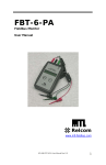
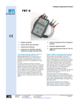
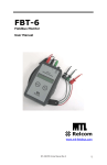
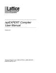
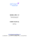
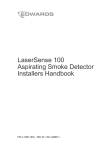
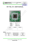
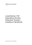
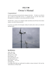
FBT-10 Fieldbus Commissioning Box User Manual www.relcominc.com 502-940 FBT-10 User Manual Rev A.0 1 Relcom, Inc. 2221 Yew St. Forest Grove, OR 97116 USA Tel: (503) 357-5607 Fax: (503) 357-0491 www.relcominc.com © Copyright Relcom, Inc. 2013 All rights reserved. No part of this manual may be reproduced, photocopied, stored on a retrieval system or transmitted without the express prior written consent of Relcom, Inc. 2 502-940 FBT-10 User Manual Rev A.0 Table of Contents Table of Contents Table of Contents ..................................................................... 3 I. Introduction ........................................................................ 4 II. Certifications ...................................................................... 5 III. Operation........................................................................... 6 IV. Use Cases ....................................................................... 13 V. Battery Management........................................................ 15 VI. Specifications .................................................................. 16 VII. Service ............................................................................ 17 VIII. Shipping and Air Travel .................................................... 17 IX. Warranty .......................................................................... 18 X. Revision History ............................................................... 19 502-940 FBT-10 User Manual Rev A.0 3 Introduction I. Introduction The FBT-10 provides a convenient, portable platform for everything needed to commission a Fieldbus segment. This is accomplished with or without mains power, and with or without a Host (DCS). Commissioning can then begin at an earlier stage in the project. Sockets in the FBT-10 provide a convenient way to connect, store, and transport Fieldbus diagnostic tools such as the FBT-6, F809F, FBT-9 and FBT-11 (please see literature on these tools for more information on their features). The unit is rugged enough to be shipped to site or checked onboard an airplane. This manual was current at the time of printing. Go to www.relcominc.com for an electronic copy of the latest version of this manual. Further information on fieldbus is available in the Fieldbus Wiring Guide, also available on the website. Summary of Features The Commissioning Box includes the following features: 4 Internal rechargeable battery or mains powered Built-in 28V, 500mA Fieldbus Power Supply Switch selectable Terminator Four short circuit protected Spur connections Host and Field Trunk connections Oscilloscope connection F809F socket FBT-6 socket FBT-9 socket Rugged “Pelican-style” case LED lights for low-light operation 502-940 FBT-10 User Manual Rev A.0 Certifications II. Certifications As of the printing of this manual, the FBT-10 does not carry any certifications. It should not be used in a hazardous area unless the area is known to be non-hazardous. 502-940 FBT-10 User Manual Rev A.0 5 Operation III. Operation WARNING: Do not remove the main panel before reading the section on Battery Replacement. Hazardous voltages may be present inside. When supplying Mains power, make sure the voltage and frequency specifications are correct – see the Specification section. The following block diagram shows how all of the components of the FBT-10 are connected together. FBT-10 Block Diagram This section explains the function of all of the switches, indicators, and connectors on the FBT-10. 6 502-940 FBT-10 User Manual Rev A.0 Operation Master Power Switch This illuminated switch enables power to all functions on the Commissioning Box except for battery charging. It is recessed to prevent accidental activation. The Master Power Switch should be OFF when not using the Commissioning Box to prevent draining the battery. FBT-9, F809F, and FBT-6 Switches These three switches enable power to the FBT-9, F809F, and FBT-6 respectively. They are not illuminated because the FBT9, F809F, and FBT-6 themselves indicate when they are powered. Light Switch Four (4) white LEDs in the upper corners of the case lid are illuminated when this switch is ON. These LEDs will provide light for the Panel when there is not enough ambient light. Shield Ground Switch When this switch is ON, a relay inside the Commissioning Box connects the Segment Shield to the Ground Terminal (next to the Mains Power Connector). Note that the Panel, Ground Terminal, and Mains Ground Terminal are all connected together internally. The purpose of this switch is to provide an easy way to ground the Segment Shield if it is not already 502-940 FBT-10 User Manual Rev A.0 7 Operation grounded. If this is what is desired, an earth or plant ground connection through the Mains Connector or Ground Terminal is required. FB Power Supply If there is already power on the Segment, the FB Power Supply Switch should NOT BE TURNED ON. If power for the Segment is not already available, this switch may be turned ON to provide power to the Segment. The switch will illuminate and the Green LEDs above the two Trunk Connectors will also come ON. The Green LEDs above the two (2) Trunk Connectors indicate Segment power regardless of the source. Notice that when switched ON, a Terminator is also connected to the Segment. Terminator This switch illuminates when turned ON and provides a Terminator on the Segment. It should only be used if another Terminator is needed on the Segment. Fieldbus requires two (2) Terminators on a Segment. Normally one is included in the Fieldbus Power Supply and the other near or part of the Fieldbus Device Coupler (Megablock). FBT-9, FBT-6 Slots These two slots are made to connect and hold an FBT-9 or FBT-6 to the Commissioning Box without using any cables. Relcom may also make other instruments in the future that fit these slots. For example, the FBT-11 will fit in the FBT-6 slot. To install the instrument, loosen the two screws fixing the Holder to 8 502-940 FBT-10 User Manual Rev A.0 Operation the Panel. Insert the instrument lining up the pins and sockets. Replace the Holder to secure the FBT device. In the figure above, the FBT-9 instrument is installed and the FBT-6 Holder has been removed and moved up to show the holder mounting holes. Please see our website for information on the FBT-6, FBT-9, and FBT-11 (www.relcominc.com). F809F Slot An F809F may be inserted into the long, narrow slot in the middle of the Panel. The “F809F” part number on the F809F label should be toward the top of the Panel. Two screws hold the F809F in place. Tighten them to keep it secured. The F809F is a Fieldbus diagnostic product made by MTL. Please see their website for more information (www.mtlinst.com). Diagnostic Segment When using the F809F, this connector is where a Host would connect to retrieve the diagnostic information about the Segment under test from the F809F. It is connected to Segment 8 on the F809F. The Commissioning box provides limited (1 device) power and two (2) Terminators for this Diagnostic Segment. Segment 2 on the F809F is connected to the Segment under test. The jumper on the F809F must be set to report its diagnostics on Segment 8. If you need to connect the F809F to a powered segment do not use the Diagnostic Segment Connector. Instead connect the segment directly to the connector on top of the F809F. The Fault LED above the connector will illuminate (red) if too much load (>40mA) is connected to this connector. See the F809F documentation at www.mtl-inst.com for more information on the F809F. 502-940 FBT-10 User Manual Rev A.0 9 Operation Field and Host Trunk Connectors These two connectors provide access to the Trunk for the Segment being tested or configured. Above each connector is a Green LED to indicate whether there is power on the Segment. The names “Field” and “Host” are somewhat arbitrary, but can be helpful to keep cables identified during testing. For example, the Field Trunk could be connected to a cable that goes to a skid while the Host Trunk would be connected to a temporary Host such as the Emerson 375/475 or the National Instruments Configurator. Device Connections The four (4) gray connectors are current limited (short circuit protected) connections to the Segment under test. A red LED above the connector illuminates if the associated connection is overloaded or shorted – see the Specification section for ratings. These connections are typically used to connect Fieldbus Devices to the Segment under test. Scope Connection Two pins in the Panel provide access to the Trunk of the Segment under test for an oscilloscope connection. CAUTION: shorting these two pins together will short the entire Segment under test. Ground Terminal This terminal may be used to ground the FBT-10 to a local earth ground. This would be desirable if the Shield for the Segment under test needed to be grounded. The FBT-10 can connect the Shield for the Segment under test to the Ground Terminal using the Shield Ground Switch (page 7). 10 502-940 FBT-10 User Manual Rev A.0 Operation Battery Status This is an LED bar graph that indicates the battery voltage. Only one LED is on at a time to indicate the current battery state. When the battery voltage falls below the lowest LED position, the LED will begin to blink at a slow rate. Charger Status These two LEDs indicate the Status of the internal battery charger. Mains Power must be supplied to the FBT-10 for the charger to work. If the Charger Status LEDs are OFF and the AC Power LED is ON, then the battery is being trickle charged – it is fully charged. If one or both of the Charger Status LEDs are ON the battery is being fast charged. Mains Connector This connector is used to provide Mains power to the FBT-10. When Mains power is being supplied to the FBT-10, the Green AC Power LED will be illuminated and the internal battery will charge. If the Mains power cable is grounded to a local ground, then the FBT-10 will also be grounded (including the Ground Terminal). 20-30VDC Output This two (2) pin connector may be used to supply power to other devices the user may need to power. A Red Fault LED illuminates if the output is shorted or trying to draw too much current. The output voltage will depend on the battery voltage or will be near 30VDC if the FBT-10 is connected to Mains power. 502-940 FBT-10 User Manual Rev A.0 11 Operation Shield Grounded LED An internal detector monitors the Shield for the Segment under test and illuminates this Green LED when the Ground Terminal and the Shield are connected together. Note that when the F809F is being used (is powered ON) and the Shield is grounded, this Green LED may blink. This is considered normal. FB PS Fault LED This Red LED indicates when there is a fault with the internal FB Power Supply (when it is being used). A solid Red LED indicates that the Segment under test is drawing too much current or is shorted. A blinking LED means that an internal fault has occurred with the FB Power Supply. If this happens, arrange to have the unit serviced at the factory. 12 502-940 FBT-10 User Manual Rev A.0 Use Cases IV. Use Cases In this section, some example use cases for the FBT-10 will be covered. Pre-Commissioning In order to configure a Fieldbus device, a working segment including a Host must be connected to it. With a portable Host and the device to configure connected to the FBT-10, communication can be established and the device configuration can be completed. The battery in the FBT-10 supports precommissioning anywhere - in the field, on a truck or barge, in a maintenance shop, etc. Training A complete Fieldbus segment on a table can be achieved by connecting a Fieldbus Device and Host to the FBT-10. This can be invaluable for demonstrations or training of personnel. Adding the F809F or FBT-6 diagnostic tools allows trainees to see diagnostic results from segments that are operating well and those that are not (when inducing disturbances with the FBT-11). The diagram above illustrates how little is required to conduct pre-commissioning or training when using the FBT-10. Depending on the type of training required, the FBT-9 could be used instead of a 375/475 or NI Configurator. 502-940 FBT-10 User Manual Rev A.0 13 Use Cases Skid Validation A skid will typically have several Fieldbus devices and a Terminator. A Fieldbus Power Supply, Terminator and Host must be connected to the skid segment to test its operation. The FBT10 contains everything to accomplish this except for the Host. Attach a portable host, such as a laptop with a National Instruments Fieldbus interface or an Emerson 375/475, and validation may begin. If Fieldbus device configuration/exercise is not required, an FBT-9 may be used instead of a portable Host. The FBT-9 is a simulated Host that will establish communication with all Fieldbus devices on the segment. See the FBT-9 product specification on our website (www.relcominc.com) for more information. Segment Checkout The FBT-10 facilitates testing a segment before it is fully complete. If the Fieldbus Power Supply is not yet online, the FBT-10 can supply power to the segment. It also provides sockets for diagnostic equipment. The FBT-6 or F809F can be used to monitor the health of the segment. The FBT-9 simulates a Host to establish communication among the Fieldbus devices. Using an FBT-11, the resilience of the segment can be tested. The segment’s robustness is measured by how well it will tolerate the adjustable disturbances imposed by the FBT-11. See the FBT-11 product specification for more information. In the above diagram, the Device Coupler and Fieldbus devices are either located on a Skid, or in the field. A 375/475 or NI Configurator is shown, but depending on the requirements, an FBT-9 docked to the FBT-10 may be used instead. 14 502-940 FBT-10 User Manual Rev A.0 Battery Management V. Battery Management The FBT-10 uses two (2) 12VDC, 8Ah Sealed Lead Acid (SLA) batteries to power the unit when Mains power is not available. It also contains a battery charger which charges the battery whenever Mains power is connected (whether the unit is ON or not) as well as a protection circuit to prevent discharging the battery too far. SLA batteries like most batteries have peculiar characteristics that are worth understanding to prolong the battery life. Discharging a battery too far will shorten its life. Although temperature dependent the self-discharge rate of a SLA battery is about 3% per month. If the FBT-10 is stored for a long period of time, it is possible that the battery may discharge below the recommended minimum and the battery life will be significantly diminished. Recommendations for increased battery life are: 1. Store at 20°C or less. 2. Recharge after each use. 3. Recharge at least annually if not in use. Master Power Switch Accidently Left On When the unit is ON circuitry monitors the battery voltage continuously. If the voltage gets too low (about 21VDC), all functions are shut down except for the monitoring circuitry. If the unit stays in this mode for about an hour, it completely shuts down – just as if the Master Power Switch was turned OFF. This situation may cause confusion because the Master Power Switch will be ON, but nothing will indicate that there is power to the unit. To reset from this condition, turn the Master Power Switch OFF and then back ON. The unit needs to be adequately charged to function properly when using battery power. 502-940 FBT-10 User Manual Rev A.0 15 Specifications VI. Specifications 2 Connector Wire Capacity 12-24 AWG, 2.5mm maximum Case Material / Size ABS / 47.24 cm x 36.83 cm x 19.56 cm Operating Temperature –10°C to +50°C Storage Temperature –40°C to +50°C Humidity 0 to 90% (non-condensing) Weight 12 kilograms (26.5 lbs.) Input Voltage 90-264VAC, 47-63Hz Device Current 30mA maximum (only one Device per spur) Device Short Circuit Current 49mA maximum Internal Fieldbus Power Supply 27.9VDC (min), 500mA (max) Maximum DC Output Current 500mA DC Output Voltage 20 - 30 VDC Battery Capacity 8Ah @ 24VDC nominal Battery Charge Time < 10 Hrs. Specifications are subject to change without notice. 16 502-940 FBT-10 User Manual Rev A.0 Service VII. Service The Commissioning Box does not contain any user serviceable parts. All adjustments and/or repairs have to be performed at the factory. If the Commissioning Box needs to be serviced, contact Relcom for return instructions. If the Commissioning Box is still covered by the limited warranty, the repairs or replacement will be made free of charge. For service outside the warranty, contact Relcom to determine the charges for the service before sending the unit back to the factory. VIII. Shipping and Air Travel The batteries in the FBT-10 are considered a “Non-spillable Sealed Lead-Acid Battery” and as such are able to be shipped and transported on airlines as checked luggage. The batteries themselves are marked similar to the following (although the way they are mounted in the FBT-10 it would be difficult to read them: “Classified DOT Class 60 dry cell. Meets air transportation requirements for transport under title 49CFR173.169 and special provision A67 as decreed by IATA and ICAO.” To facilitate airport inspection by agencies such as TSA, there is a sticker inside the case lid with instructions for opening the Panel so the Airport Inspector can verify what is under the panel. This is required because the batteries look like big black bricks to their X-ray machine. We have traveled with the unit as checked baggage with no issues. 502-940 FBT-10 User Manual Rev A.0 17 Warranty IX. Warranty Relcom, Inc. warrants the Commissioning Box to perform as described in this manual under normal use for a period of one year after delivery to the original purchaser. This warranty does not apply if the Commissioning Box has been disassembled, modified or used for purposes other than those described in this manual. Upon verification of any defect, Relcom, Inc. shall, at its option, repair or replace the defective unit. In no event does Relcom, Inc. assume liability for incidental or consequential damages. This warranty is the extent of the obligation or liability assumed by Relcom, Inc., and no other warranty or guarantee is either expressed or implied. Relcom, Inc. reserves the right to make design changes to the Commissioning Box without notice and with no obligation to make the same or similar changes to units previously manufactured. Relcom, Inc. has made every effort to assure the accuracy of the information contained in this manual. Relcom is not, however, responsible for any errors or omissions. Please contact us with any questions or suggestions. 18 502-940 FBT-10 User Manual Rev A.0 Revision History X. Revision History Revision Date Description A.0 09/05/2013 Original Release Relcom, Inc. 2221 Yew St. Forest Grove, OR 97116 USA Tel: (503) 357-5607 Fax: (503) 357-0491 www.relcominc.com 502-940 FBT-10 User Manual Rev A.0 19